

Page 1
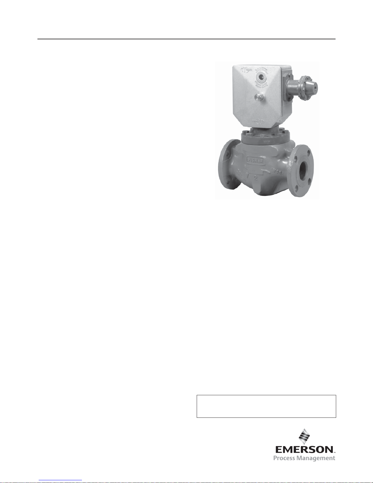
Type OSE
Instruction Manual
D103687X012
November 2015
SLAM-SHUT VALVE
CONTENTS
Introduction ........................................................................ 1
Characteristics ................................................................... 1
Labelling ............................................................................. 2
Dimensions and Weights ................................................... 3
Operation ........................................................................... 4
Installation .......................................................................... 4
Commissioning .................................................................. 5
Maintenance ...................................................................... 6
Spare Parts ........................................................................ 7
Figure 1. Type OSE Slam-Shut Valve
The OSE is in conformity with the
Pressure Equipment Directif PED 97/23/CE
and is classifi ed under category IV.
CHARACTERISTICS
Material
Body Steel
Bonnet Steel
Orifi ce Stainless steel
Valve plug Stainless steel
O-rings Nitrile
Connections
Inlet/Outlet: ISO PN 100 B (ANSI 600 RF)
ISO PN 50 B (ANSI 300 RF)
ISO PN 20 B (ANSI 150 RF)
Other connections available
(contact factory)
ISO PN 16 B, 25 B, 40 B
Impulse (IS): 1/4’’ NPT threaded
Mechanism box vent (E): 1/4” NPT threaded
Impulse diameter: Tube interior Ø 8/10 mm
Safety contact: See D103683X012 manual
INTRODUCTION
Scope of Manual
This manual provides installation, start-up, maintenance,
and parts ordering information for the Type OSE SlamShut Valve.
Information on other equipment used with this slam-shut
valve is found in separate manuals.
Product Description
The OSE Slam-Shut Valve protects transmission and
distribution networks or pipe lines supplying industries and
commercial businesses.
It permits the gas fl ow to be cut off rapidly and totally in the
case of under or over regulator pressure.
The OSE exists in DN 25 (1”) to DN 150 (6”). DN 200 (8”)
and DN 250 (10”) are covered by the OSE LS.
The OSE consists of:
• A body with a removable orifi ce, enclosed by a bonnet
• A valve plug with integral bypass, tightshut by an O-ring
• A release relay type OS2 including:
- A mechanism box (BM)
- A safety manometric box (BMS) to be connected on
the outlet side of the pressure regulator.
Page 2
2
Type OSE
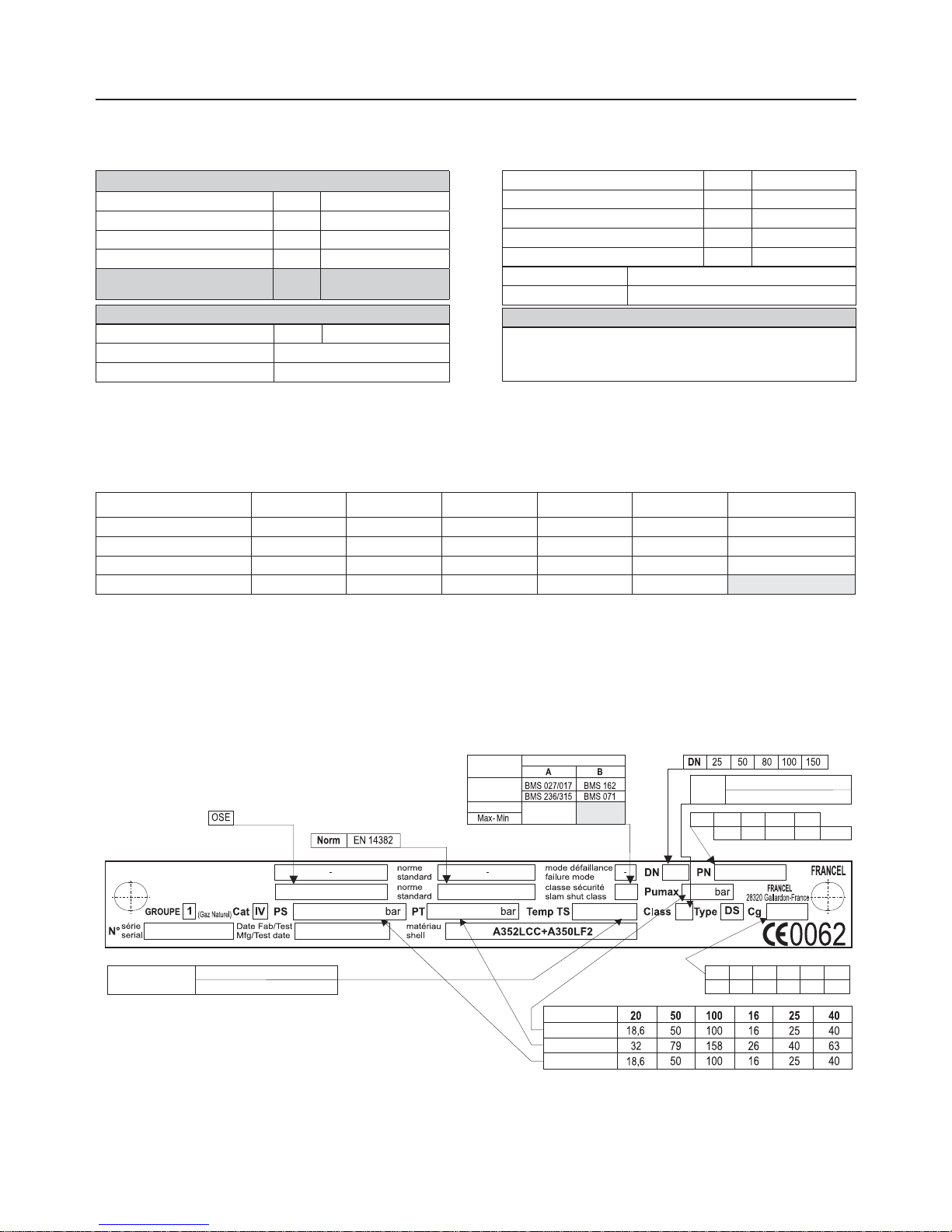
LABELLING
- 20 / + 60 °C (bolting class 8-8)
- 30 / + 71 °C (bolting A320L7)
CLAPET DE SECURITE
SLAM-SHUT VALVE
DN 25
505 2110 4670 7860 14850
50 80 100 150
PN 40 B
20 B1 50 J 50 B1 100 J 100 B2
25 B 16 B 20 J
Class
2 (bolting class 8-8)
- (bolting A320L7)
Temperature TS
PN
Pumax
PT
PS
Cg
Other connections available (contact factory)
Security Class
BMS setting
Max only
Min only
All BMS
types
DD MM YEAR
C60
(1) BMS : Safety manometric box
(2) Differential strength (depending on BMS chosen)
(3) Temperature depending on bolting material (see label)
Table 1. Technical Characteristics of the Type OSE Slam-Shut Valve
DN 25 50 80 100 150 Bypass
Cg 505 2110 4670 7860 14850 25
C1 35 35 35 32 33 35
ΔP max (bar) > 25 > 25 25 10 6 100
Relay travel (mm) 35 35 50 50 50
C50
Table 2. Flow Coeffi cient, ΔP max, Relay travel
Figure 2. Label for Type OSE Slam-Shut Valve
OPERATING PRESSURE
Body, valve plug PS 100 bar maxi
Associated BMS
(1)
according to size PSD 10 à 100 bar
Maximum Inlet Pressure Pumax 100 bar
Type DS Differential strength
(2)
OPERATING TEMPERATURE
(3)
TS
- 20 / 60 °C
- 30 / 71 °C
SLAM-SHUT
Sizes available DN 25, 50, 80, 100, 150
Norm EN 14382
Operating class A or B (see label, fi gure 2)
Accuracy AG 2,5 – 5 (Piston)
Setpoint range
Wdu-Wdo
0,010 à 100 bar
Response time ta < 1 s
Max Differential (valve closed)
∆P max
100 bar
Max Differential (valve open)
∆P max
Voir tableau 2
Rearming Manually after rectifi cation of fault
Position indicator On mechanism box
FLUID
Group 1 and 2 according to PED 97/23/CE, 1st and 2nd family gas according
to EN 437, or other gases (compressed air, nitrogen).
The gas must be noncorrosive, clean (fi ltration on inlet side necessary) and dry
Page 3
3
Type OSE
DIMENSIONS AND WEIGHTS
C52
D
25
A
B
C max
E
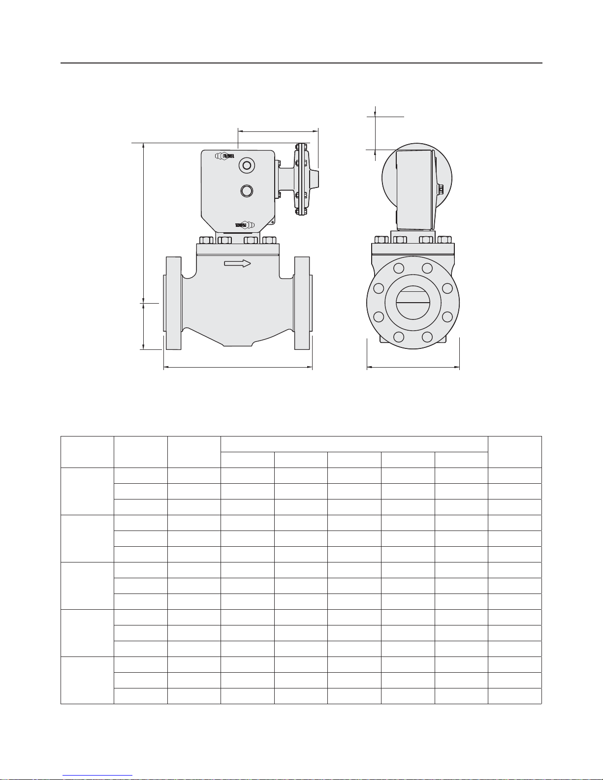
Figure 3. Type OSE Slam-Shut Valve Dimensions
Other PN16/25/40: contact factory
DN PN (B) ANSI (RF)
DIMENSIONS
WEIGHT (kg)
A B C Max D E
25
20 150 185 54 334 220 116 14
50 300 197 62 334 220 124 16
100 600 210 62 334 220 124 17
50
20 150 254 76 346 220 152 26
50 300 267 83 346 220 165 29
100 600 287 83 346 220 165 32
80
20 150 298 95 380 220 190 43
50 300 318 105 380 220 210 48
100 600 337 105 380 220 210 55
100
20 150 353 114 420 220 229 74
50 300 368 127 420 220 154 82
100 600 394 137 420 220 273 98
150
20 150 451 140 424 220 357 150
50 300 473 159 424 220 357 166
100 600 508 178 424 220 357 202
C53
Table 3. Type OSE Slam-Shut Valve Dimensions and Weights
Page 4
4
Type OSE
OPERATION
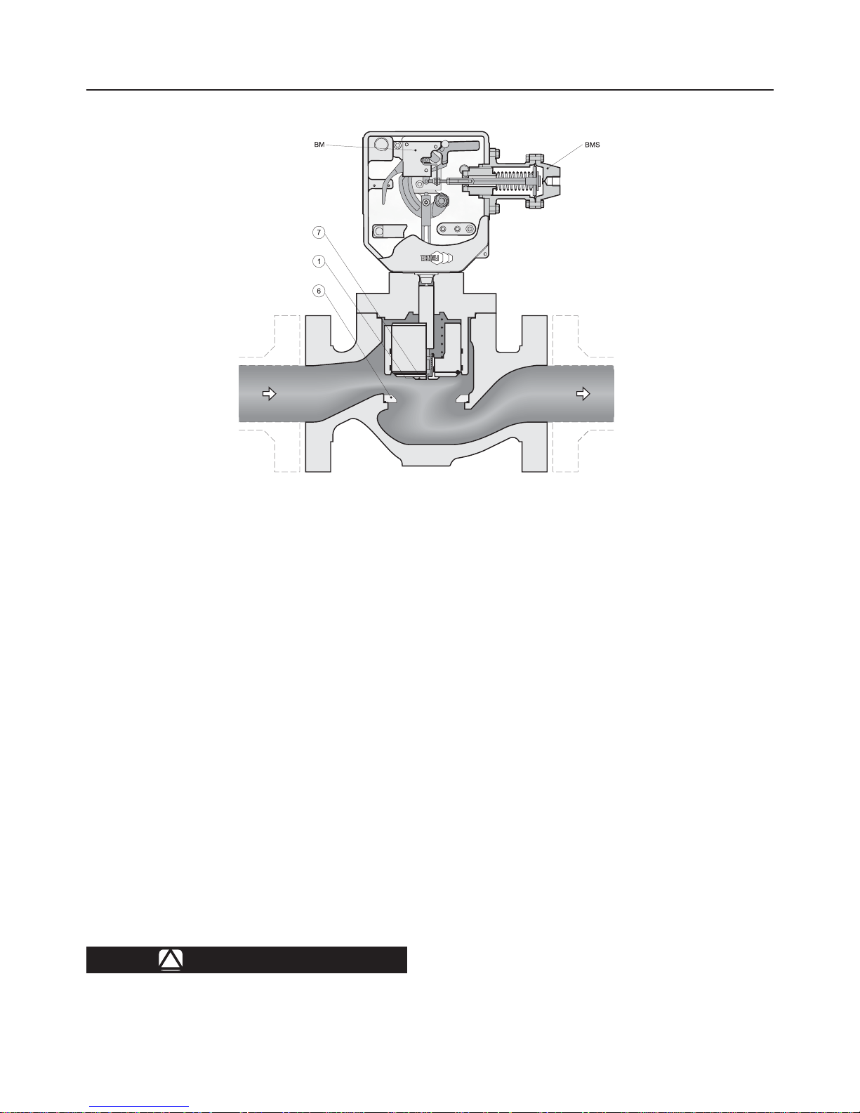
The pressure of the zone to be protected (generally the pipe
line on the outlet side of the pressure regulator and situated
after the slam shut valve) activates the safety manometric
box BMS.
If pressure rises above the release set point the release
relay frees the valve plug (key 7).
Through the action of the weight of the valve plug, the
closing spring and the fl uid (attempting to close), the valve
plug will seat into the orifi ce (key 6).
The gas fl ow is obstructed until the mechanism box is
manually rearmed.
To reopen the valve plug an equal pressure balance on inlet
and outlet sides is required.
The mechanism box is rearmed after opening the internal
bypass (key 1).
Rearming and balancing are achieved at the same time.
INSTALLATION
!
AVERTISSEMENTS
All interventions on the equipment should
only be performed by qualifi ed and
trained personnel.
C51
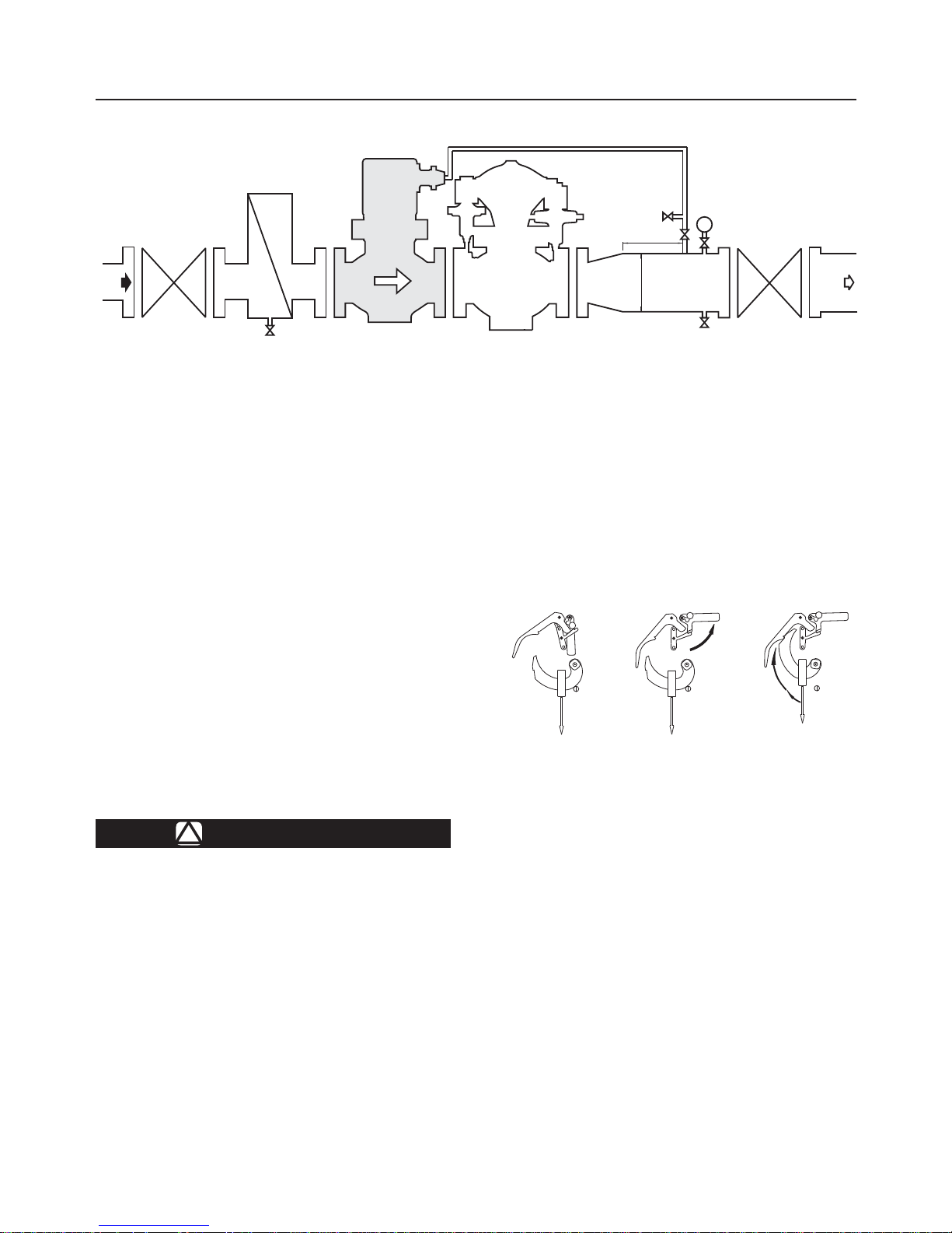
Figure 4. Type OSE LS - Principle of Operation
The slam shut valve is installed on the
inlet side of the regulator, on the horizontal
pipeline. The mechanism box should be
situated on top (see above schematic) or on
top for versions DN 25-50-80.
Installation according to EN12186 is recommended.
Install according to direction of the fl uid fl ow
(see arrow).
When assembling with adjacent elements,
care must be taken not to create pressure
force on the body and the assembling
elements (bolts, O-rings, fl anges) should be
compatible with the geometry and working
conditions of the equipment.
If the case arises a support must be used to
avoid pressure force on the body (a support
can be installed under the fl anges).
Connect the safety manometric box (IS) to
the impulse at 4D on the outlet pipe.
It is recommended to install an isolation
valve (R1) and an atmospheric valve (R2), which
can be useful for tripping and verifi cations.
No modifi cation should be made to the
structure of the equipment (drilling, grinding,
soldering ...).
Verify that the inlet side is protected by an
appropriate device(s) to avoid exceeding the
limits of utilization (PS, TS).
Page 5
5
Type OSE
Safety contact: see D103683X012 manual
C54
Pu Pd
REGULATOR D
E
IS
4 D
Figure 5. Type OSE Slam-Shut Valve Installation Schematic
Verify that the limits of utilization correspond
to the appropriate operating conditions.
Verify that the safety manometric box (BMS)
and spring correspond to the appropriate
operating conditions on the outlet side of the
regulator.
The equipment should not receive any type
of shock, especially the release relay.
The user should verify or carry out a
protection adapted to the environment.
Fire, seismic and lightening are not taken
into consideration for standard regulators.
If required, a special product selection and/
or specifi c calculations may be supplied
according to specifi c requirements.
If the slam-shut is classifi ed under operating
class B the
BMS diaphragm should be
checked periodically.
COMMISSIONING
!
WARNING
All interventions on the equipment should
only be performed by qualifi ed and
trained personnel.
Preliminary verifi cations
Start-up positions
• Inlet and outlet valves
→ Closed
Verify absence of pressure between inlet and outlet valves
• Slam-shut valve plug
→ Closed
• Impulse isolation valve
→ Closed
• Impulse atmospheric valve
→ Open
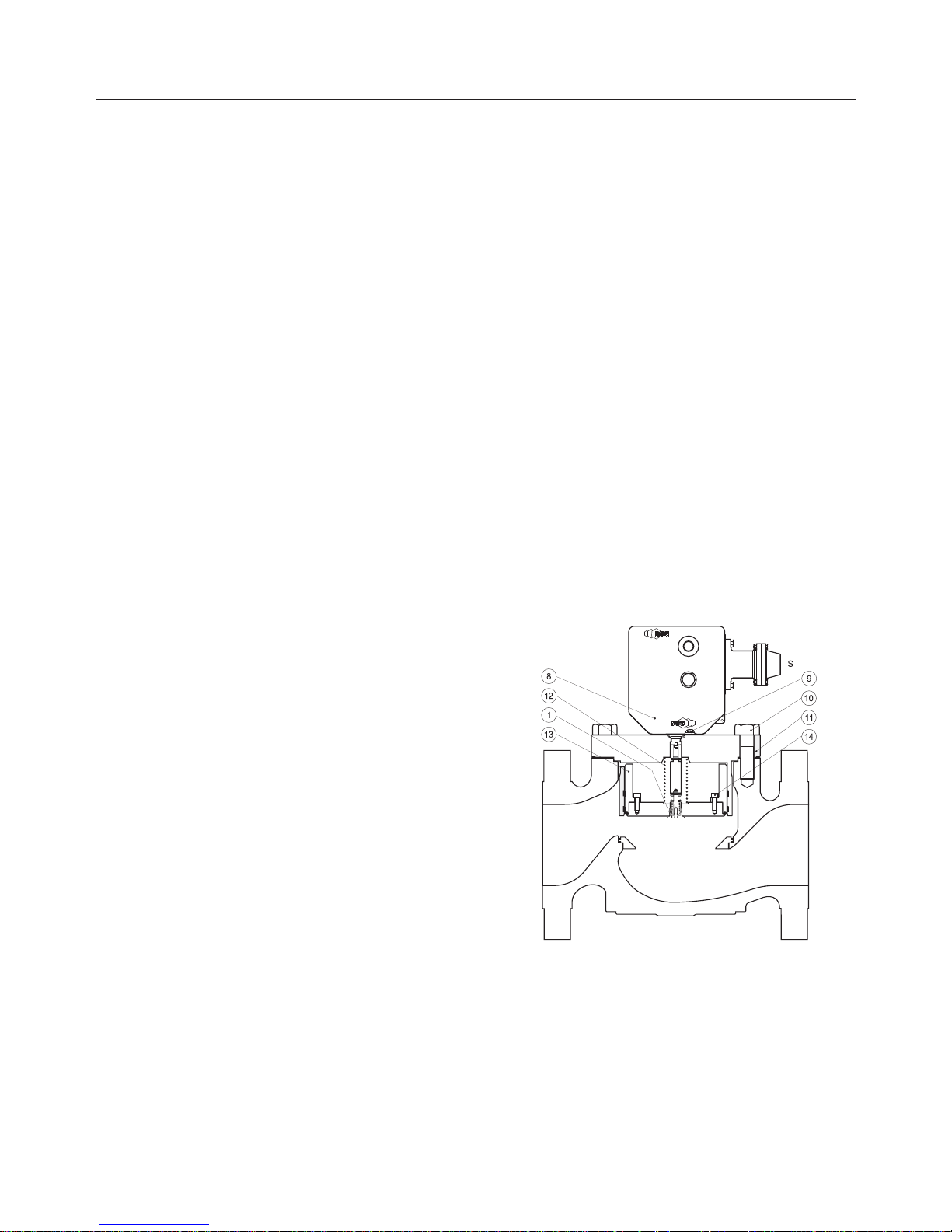
Setpoint Verifi cation
Using the atmospheric valve, inject a pressure equal to the
pressure foreseen for the regulator
• 1st release relay stage
→ Set (Stage 1)
TRIGGERED POSITION
TRAVEL
STOP
TRAVEL
STOP
TRAVEL
STOP
1
2
3
C59
Figure 6. Setpoint Verifi cation
STAGES 2 & 3STAGE 1
• Slam shut valve
→ Open (Stages 2 & 3)
→ Progressively increase the pressure to reach tripping
→ Adjust setting if necessary (D103683X012 manual)
Note the set point value on the equipment or mark it in a
commissioning document.
Positions before Commissioning
• Impulse isolation valve
→ Open
• Impulse atmospheric valve
→ Closed
• Slam shut valve plug
→ Closed
The equipment is ready for commissioning
Page 6
6
Type OSE
C57
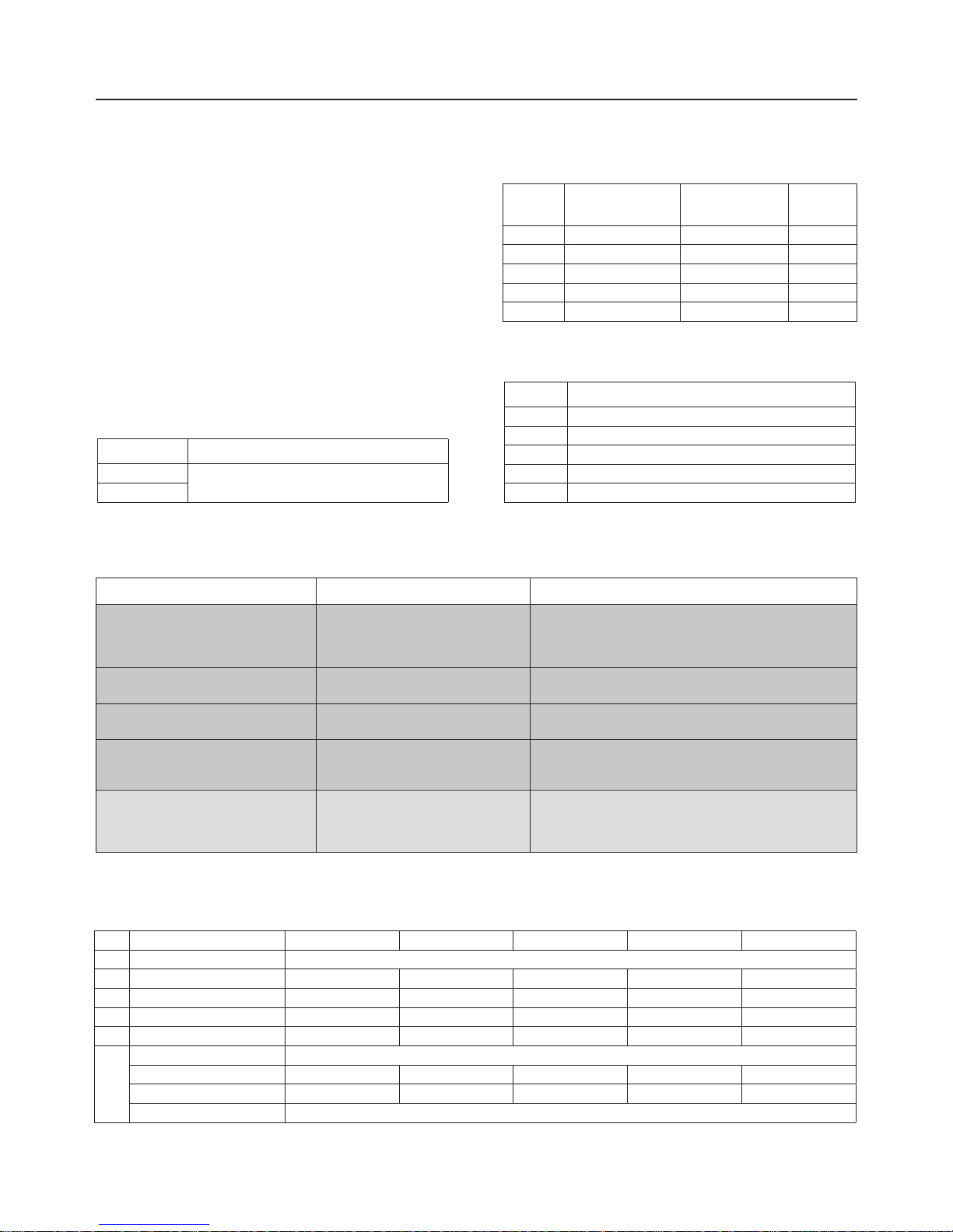
Figure 7. Type OSE - Commissioning Schematic
Commissioning (max. only or max. & min.)
• Inlet valve
→ Open slowly
• Slam-shut bypass
→ Open slowly (stage 2)
• Regulator
→ Put into operation (see corresponding manual)
• 1
st
release relay stage
→ Set (Stage 1)
• Slam shut valve plug
→ Open (Stage 3)
• Outlet valve
→ Open slowly
The equipment is commissioned
After checking and commissioning the release relay it is
recommended to seal it
MAINTENANCE
Servicing Check
Recommended frequency:
• Twice yearly minimum
Verifi cation:
• Tripping and tripping value
• Slam-shut tightness
Departure positions
• Inlet valve
→ Open
• Outlet valve
→ Open
• Slam-shut
→ Open
• Regulator
→ In operation
Inlet and outlet sides of regulator under pressure
Tripping verifi cation
• Inlet valve
→ Closed
• Outlet valve
→ Closed
• Regulator Increase setpoint to reach tripping
(without exceeding the outlet limits)
Disassembly
Recommended frequency:
• Every 4 to 6 years (or less depending on operating
conditions)
• In the case of BMS 162 or 071, it is highly recommended to
check the condition of the diaphragm once yearly
Verifi cation:
• Condition of O-rings, diaphragm, and lubrication
Replacement:
• O-rings, diaphragm
Tools:
• Spanners 10, 13, six-sided wrench 6
• Spanners According to DN size
• Francel spanner ref. 197125 (bypass and pin disassembly)
• Valve plug closed
• Close inlet and outlet valves
• Bleed off outlet pressure
• Bleed off inlet pressure
• Unscrew impulse connection IS
• Remove BM cover (key 8)
• Unscrew fastening screw (key 9)
• Remove cap
• Remove BM
• Unscrew screws (key 10)
• Remove bonnet (key 11)
• Remove spring (rep. 12) and slam-shut valve plug
(key 13)
• Unscrew bypass (key 1)
• Unscrew screws (key 14) (DN 100 and 150)
The removal of the orifi ce (not recommended) requires a
special extraction tool
Reassembly
• Perform the above operations in reverse order (respect
tightening torques)
• Replace O-rings at each disassembly
• The valve plug should be maintained in an upright position
using the packing gland to facilitate it’s removal
Page 7
7
Type OSE
• Precaution should be taken when removing or replacing
the valve plug to avoid damaging the segments
• Lubricate screws before tightening
• Lubricate O-rings (silicone grease) except for the valve
plug O-ring
• Lightly lubricate the stem (silicone grease)
• Lubricate the release relay mechanism (yoke and bolt)
(molybdenum graphite grease)
• Lubricate the BMS spring (molybdenum graphite grease)
A special tool is required when installing a new orifi ce
Table 7. Troubleshooting for Type OSE Slam-Shut Valve
Table 5. Torques for Connecting Part Screw
(key 10, Fig. 7)
DN Dimensions Spanner (inches)
Torque
(N.m)
25 9/16-12
X 1 3/4 13/16’’ 110
50 1/2-13
X 1 1/2 3/4’’ 110
80 5/8-11
X 1 3/4 15/16’’ 175
100 3/4-10 X 2 1/4 1’’1/8 260
150 1-8
X 2 3/4 1’’1/2 510
C58a
Table 6. Torques for Bypass (key 1. Fig. 7)
DN Torque (N.m)
25 14
50 14
80 20
100 24
150 24
C58b
C58c
Key Torque (N.m)
9
15
14
Table 4. Torques (key 9 & 14, Fig. 7)
SYMPTOMS CAUSE ACTIONS
If the valve will not close Operating fault
Check the release relay
Check the valve plug
or contact after-sales
If the valve closes Operating correctly
Observe the evolution of the outlet pressure
(check tightness)
If the outlet pressure in the slam shut is
decreases
External leak
Locate and seal the leak
or contact after-sales
If the outlet pressure in the slam shut is
constant
Bleed off the outlet side of the regulator
Observe the evolution of the outlet pressure
(check tightness)
If the outlet pressure increases Internal leak
Check the slam shut valve plug
Check the orifi ce
Check the bypass
or contact after-sales
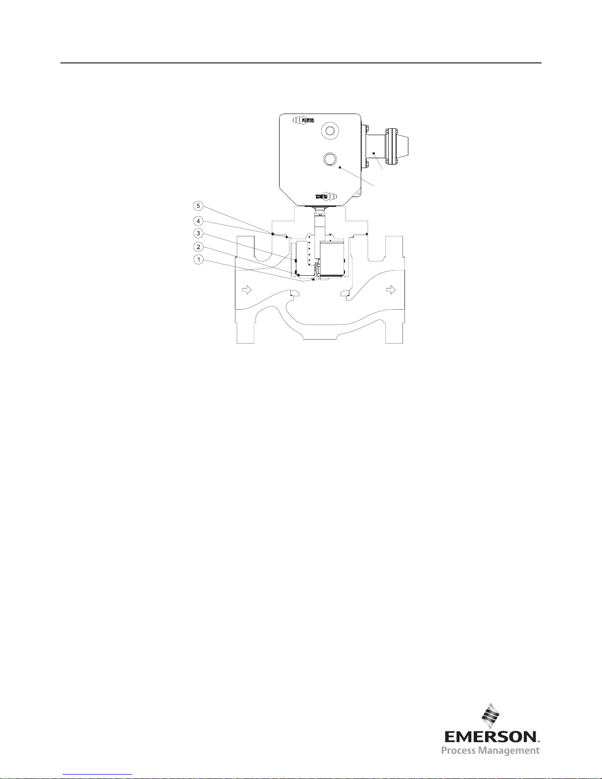
Key Description DN 25 DN 50 DN 80 DN 100 DN 150
1 Bypasse 180977
2 Valve plug O-ring 400257 400263 400258 400260 400261
3 Segments 401950 401951 401952 401953 401954
4 O-ring 400298 400295 400297 400296 19B0359X12
5 O-ring 400009 400024 400259 400045 400262
Packing gland “Kit” 197395
Set of O-rings* 197447 197448 197449 197450 197451
Spare parts kit** 197452 197453 197454 197455 197456
Release Relay Type OS2 See D103683X012 manual
(*) Set of O-rings and segments including O-rings key 2, 3, 4, 5 (**) Spare-parts kit including set of O-rings, bypass (key 1) and bypass disassembly spanner
Table 8. Spare Parts for Type OSE Slam-Shut Valve
SPARE PARTS
Page 8
Type OSE
The Emerson logo is a trademark and service mark of Emerson Electric Co. All other marks are the property of their prospective owners.
Francel is a mark of Francel SAS, a business of Emerson
Process Management.
The contents of this publication are presented for informational purposes only, and while every effort has been made to ensure their accuracy, they are not to be construed as warranties or guarantees,
express or implied, regarding the products or services described herein or their use or applicability. We reserve the right to modify or improve the designs or specifi cations of such products at any
time without notice.
Emerson Process Management does not assume responsibility for the selection, use or maintenance of any product. Responsibility for proper selection, use and maintenance of any Emerson Process
Management product remains solely with the purchaser.
©Emerson Process Management Regulator Technologies, Inc., 2015; All Rights Reserved
Industrial Regulators
Emerson Process Management
Regulator Technologies, Inc.
USA - Headquarters
McKinney, Texas 75070, USA
Tel: +1 800 558 5853
Outside U.S. +1 972 548 3574
Asia-Pacifi c
Shanghai 201206, China
Tel: +86 21 2892 9000
Europe
Bologna 40013, Italy
Tel: +39 051 419 0611
Middle East and Africa
Dubai, United Arab Emirates
Tel: +971 4811 8100
For further information visit www.emersonprocess.com/regulators
Natural Gas Technologies
Emerson Process Management
Regulator Technologies, Inc.
USA - Headquarters
McKinney, Texas 75070, USA
Tel: +1 800 558 5853
Outside U.S. +1 972 548 3574
Asia-Pacifi c
Singapore 128461, Singapore
Tel: +65 6777 8337
Europe
O.M.T. Tartarini s.r.l. Via P. Fabbri 1,
I-40013 Castel Maggiore (Bologna), Italy
Tel: +39 051 419 0611
Francel SAS, 3 ave Victor Hugo,
CS 80125 - Chartres 28008, France
Tel: +33 2 37 33 47 00
Middle East and Africa
Dubai, United Arab Emirates
Tel: +971 4811 8100
TESCOM
Emerson Process Management
Tescom Corporation
USA - Headquarters
Elk River, Minnesota 55330-2445, USA
Tels: +1 763 241 3238
+1 800 447 1250
Asia-Pacifi c
Shangai 201206, China
Tel: +86 21 2892 9499
Europe
Selmsdorf 23923, Germany
Tel: +49 38823 31 287
O.M.T. Offi cina Meccanica Tartarini S.R.L., R.E.A 184221 BO Cod. Fisc. 00623720372 Part. IVA 00519501209 N° IVA CEE IT 00519501209,
Cap. Soc. 1.548 000 Euro i.v. R.I. 00623720372 - M BO 020330
Francel SAS, SIRET 552 068 637 00057 APE 2651B, N° TVA : FR84552068637, RCS Chartres B 552 068 637, SAS capital 534 400 Euro
BMS
BM
C56
Figure 8. Type OSE Spare Parts
 Loading...