

Emerson Liebert PSA 1000VA, Liebert PSA 1500VA, Liebert PSA500MT3-230U, Liebert PSA650MT3-230U Quick Start Manual
Page 1
Liebert® PSA
™
Quick-Start Guide - 1000VA/1500VA, 230V
IMPORTANT SAFETY INSTRUCTIONS
• Do not connect equipment that may overload the UPS or demand half-wave
rectification, such as a laser printer.
• Connect the UPS only to an earthed / grounded socket that meets electrical safety
guidelines.
• Locate the UPS near a wall socket. Do not use an extension cord between the UPS and
the socket.
• Use CE-marked cables only for connections between mains, the UPS and equipment.
• The Liebert PSA has been designed for small office/home office use only; it is NOT
recommended for use in life-support applications.
• In the event of an emergency, press the OFF button and disconnect the power cord
from the AC mains to properly disable the UPS.
• Do not attach power strips or surge suppressors to the UPS.
• Do not attempt to service any parts inside the UPS except the batteries. Failure to adhere
to this could cause personal injury or equipment malfunction and void the warranty.
• For technical support:
• Visit www.liebert.com or
• Send an e-mail to [email protected].
SETUP
UPS CONTROLS AND CONNECTIONS
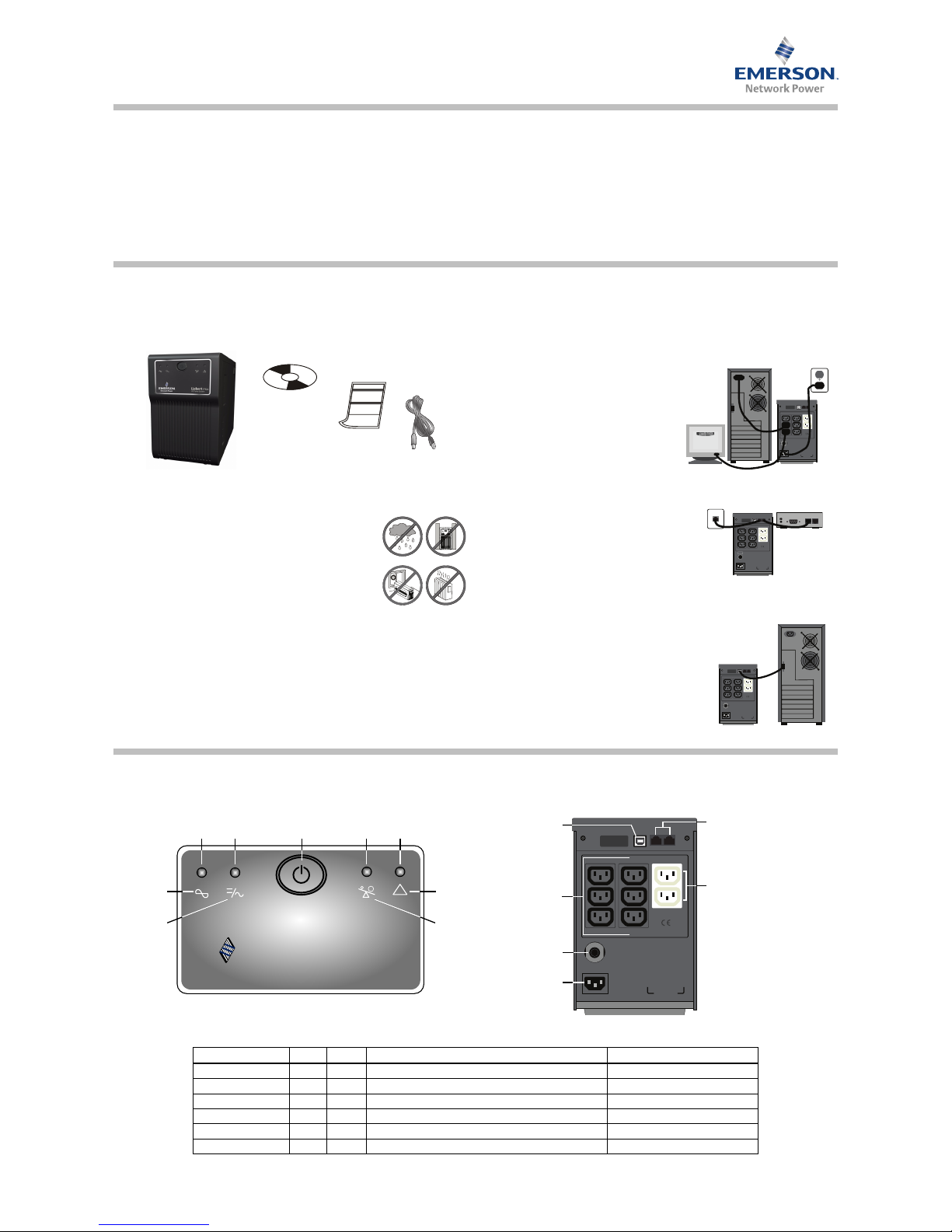
Step 1 Inspect the Package
Inspect the package and the UPS upon receipt. Notify the carrier and dealer of visible
damage.
Step 2 Decide Where to Place the UPS
The UPS must be placed indoors, protected from water, direct
sunlight and excessive heat.
Provide at least 100mm (4") of clearance on all sides of the unit
for proper ventilation.
Step 3 Charge the UPS Battery Before
Use
The UPS battery is not charged before shipping. It MUST be charged before use.
• Connect a user-supplied power cord from the UPS to a wall socket and charge for at
least eight hours.
Note: If battery is placed in storage, charge the battery every six months if kept at
-15°C to +29°C (5°F to 85°F)—or every three months if kept at 30°C (86°F) or higher.
Step 4 Start the UPS
After the battery is fully charged:
• Turn on the UPS by pressing the On/Off button (see Figure 1 below).
LED 1 should be illuminated (green), indicating the UPS is operating in Normal Mode.
Step 5 Connect the Loads
The UPS has three battery backup sockets that
provide power when the UPS operates on battery (see Figure 2 below).
• Plug the loads into the battery backup sockets
on the rear of the UPS.
Caution: Do not connect a laser printer to the
UPS.
Step 6 Connect the Network Surge Protection
The UPS has two RJ-45 jacks for network lines (see
Figure 2 below).
• Connect a single-line network cable into the RJ-45
network surge protection IN jack on the rear of the
UPS.
• Connect an RJ-45 cable from the OUT jack on the
rear of the UPS to a port on a PC or network device such as a router.
Step 7 Set Up Liebert shutdown software
To start using the Liebert shutdown software:
• Install the Liebert shutdown software. See the software
user manual for installation instructions.
• Connect one end of the USB cable (supplied) to the
USB port on the rear of the UPS. Connect the other end
to a USB port on the computer. See the software user
manual for operating instructions.
UPS
USB
cable
Quick-start
guide
Liebert
shutdown
software
CD
USB
Battery Power Supply
AC OUTPUT
AC INPUT
Full Time Surge Protection
IN OUT
USB
Battery Power Supply
AC OUTPUT
AC INPUT
AC INPUT
FUSE
Full Time Surge Protection
IN OUT
USB
Battery Power Supply
AC OUTPUT
AC INPUT
Full Time Surge Protection
IN OUT
UPS Status, Alarm Conditions and Alerts
Condition LED Color Solid/Flashing Audible Alarm
Normal Mode LED 1 Green Solid (steady glow) (None)
Battery Mode LED 2 Amber Flashes every 3 seconds Every 3 seconds
Battery Low LED 2 Amber Flashes every 1 second till end of discharge (EOD) Every 1 second
Overload LED 3 Amber Solid (steady glow) until load drops or breaker trips Continuous
Battery Replacement LED 4 Red Flashes every 1 second for 5 seconds only Every 1 second for 5 seconds only
Fault LED 4 Red Solid (steady glow) until UPS shuts down after 5 seconds Continuous until UPS shuts down
USB
Battery Power Supply
AC OUTPUT
Full Time Surge Protection
IN OUT
Surge sockets (2)
IEC 320 C13
RJ-45 jacks (2) - network
protection
USB
interface
Battery backup
sockets (6)
IEC 320 C13
Mains
breaker
AC mains
inlet
LED 2
(amber)
!
EMERSON
™
Network Power
Liebert
®
PSA
AC Power Sys tem
LED 3
(amber)
Fault
symbol
Overload
symbol
Mains
symbol
On/Off
button
LED 1
(green)
LED 4
(red)
Battery
symbol
Figure 2 - Rear PanelFigure 1 - Front Panel LEDs
Page 2
© 2008 Liebert Corporation
All rights reserved throughout the world. Specifications subject to change without notice.
® Liebert is a registered trademark of Liebert Corporation.
All names referred to are trademarks or registered trademarks of their respective owners.
SLI-23301_REV0_03-08
Technical Support / Service United States
800-222-5877 (Outside U.S. 614-841-6755)
[email protected]
Web site: www.liebert.com
1050 Dearborn Drive
P.O. Box 29186
Columbus, OH 43229
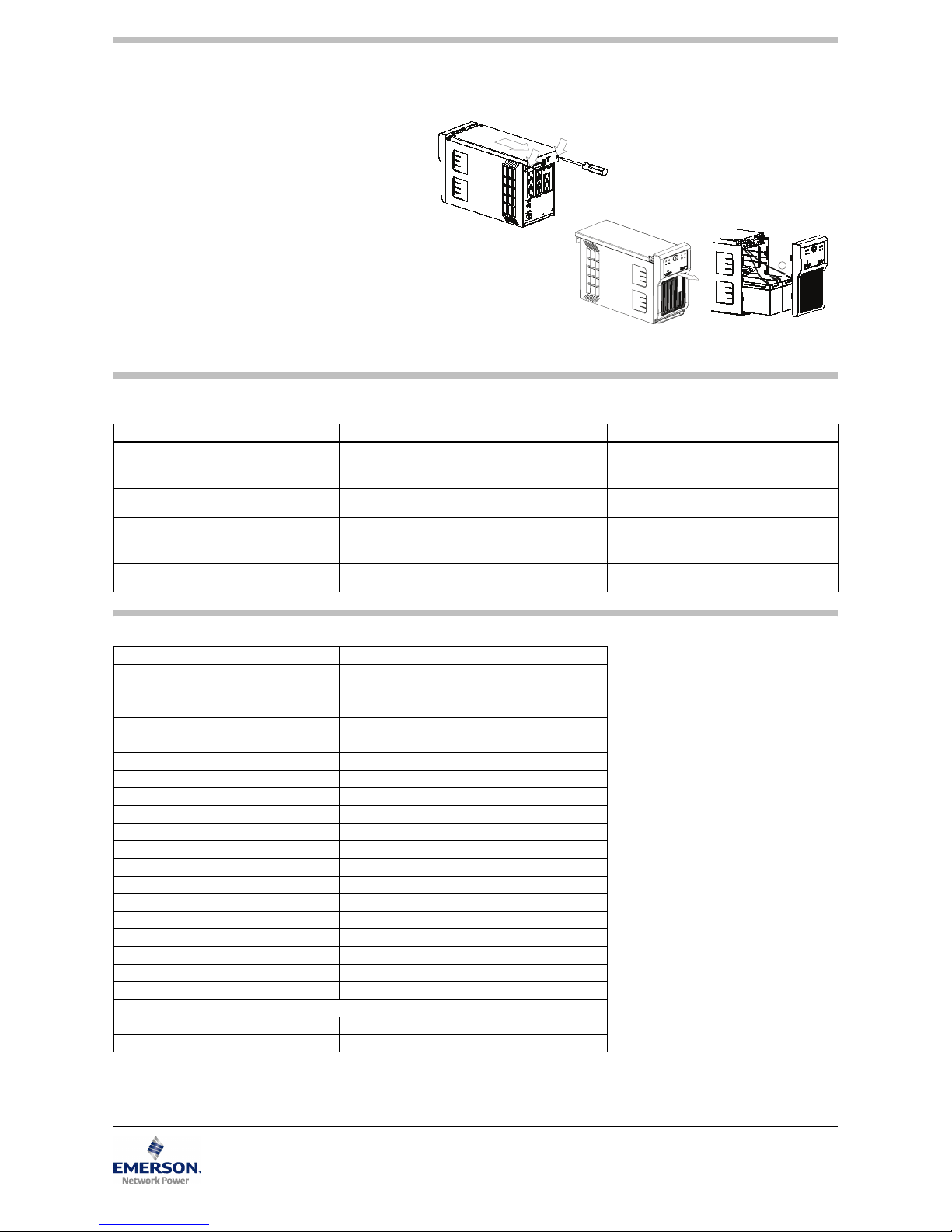
REPLACING THE BATTERY
To replace the battery:
1. Turn off all connected loads, then turn off the UPS (batteries are NOT
hot-swappable).
2. Use a Phillips head screwdriver to remove the two top cover screws from
the back of the UPS.
3. Slide the top panel backward 13mm (1/2"). Slide the front panel upward,
then pull outward to remove it
4. Gently pull the batteries out of the UPS.
5. Remove the black wire from the negative (-) terminal and the red wire from
the positive (+) terminal.
6. Verify that the replacement battery matches the dimensions and battery
type in the Specifications section below.
7. Connect the battery leads to the new batteries. Be sure to reconnect the
red wire to the positive (+) terminal and the black wire to the negative (-)
terminal.
Note: Small sparks may occur at the battery connectors during
reconnection.
8. Slide the batteries into the UPS.
9. Reposition the front panel and slide downward until it slides into place.
Slide the top panel forward until flush with the front panel. Reinsert the two
top cover screws removed in Step 2.
Dispose of the old batteries properly at an appropriate recycling facility.
TROUBLESHOOTING
If the UPS malfunctions during operation, check the following chart for proper adjustment. For further assistance, please contact your local Emerson Network Power representative.
SPECIFICATIONS
Problem Possible Causes Solutions
Mains is normal, but LED 1 is not illuminated.
The UPS may not be turned on.
The power cord may not be connected properly.
The upstream mains circuit breaker may be tripped.
• Press the On/Off button to turn on the UPS.
• Connect the power cord securely into a wall socket.
• Reset the circuit breaker.
LED 2 flashes (amber) every 3 seconds, but there is
no output power.
Battery voltage may be too low. • Recharg e the UPS for 8 hours.
Alarm buzzer beeps continuously although mains is
normal.
The UPS may be overloaded (check LED 2). • Disconnect some equipment from the UPS.
UPS does not provide expected backup time. The UPS battery reached end of life. • Replace the internal battery.
The UPS is on and connected to mains, but fails to
operate properly.
Mains may be outside the unit’s operating range.
• If mains is normal, try reconnecting mains and
restarting the UPS.
Model Number PSA1000MT3-230U PSA1500MT3-230U
Capacity (VA/W) 1000/600 1500/900
Net Weight, kg (lb.) 9.5 (20.9) 11.6 (25.6)
Shipping Weight, kg (lb.) 10.7 (23.6) 12.8 (28.2)
Dimensions - W x D x H, mm (in.) 147 x 360 x 234 (5.8 x 14.2 x 9.2)
On-Line Mains Voltage 160-287VAC
On-Line Frequency 50/60Hz ±5Hz
Output Voltage (Mains Normal) Typical 185-252VAC
Output Voltage (Battery Operation) 230VAC ±5%
On-Battery Wave Form Stepped sinewave
Battery Type - VDC x Ah x Quantity 12V x 7.2Ah x 2 12V x 9Ah x 2
Typical Recharge Time 6-8 hours to 90%
Battery Run Time*
60-100 minutes
Audible and Visual Audible alarm / LED
Backup Sockets IEC 320 C13 (6)
Surge Sockets IEC 320 C13 (2)
Operating Temperature, °C (°F) 0 to 40 (32 to 104)
Storage Temperature, °C (°F) -15 to 40 (5 to 104)
Operating / Storage Relative Humidity 0%-90%, non-condensing
EMI Classification Class B
Agency
Safety IEC62040-1-1
Transportation ISTA Procedure 1A Certification
* Battery run time may vary depending on load
-
Steps 4 and 5
Steps 2 and 3
 Loading...