

Page 1

Surge Protection
For Business-Critical Continuity
™
Liebert®LM Series
Continuous Protection For Your Business
Page 2

The LM Series:
The most advanced, cost-effective product line in the industry
The LM is a surge protective device (SPD) that offers
continuous protection from damaging transients and
electrical line noise. The LM utilizes patented circuitry to
monitor the status of all protection modes, including neutral
to ground. Should protection be unavailable in any mode,
the green LED will be extinguished, and the red LED will be
illuminated. In addition, high isolation form C dry contacts
provide for remote monitoring of suppression system failure,
under voltage, and phase and power loss. LM patented
suppression integrity monitoring indicates failure for
both shorted or opened suppression components.
The LM Series can be a facility-wide
product family and may be installed
from service entrances to distribution
panels to branch panels.
n
Commercial buildings
n
Institutional facilities
n
Industrial plants
n
Any facility that has an environment
with electronics-based equipment
At A Glance
n
Modular design allows for flexibility
n
Surge suppression range up to
500 kA per phase
n
Industry’s highest surge current
repeatability
n
Internal/external monitoring,
including neutral to ground
n
UL rated 200k AIC with component
level fusing for safe operation
n
All modes of protection standard,
any combination optional
n
Sine wave tracking, EMI/RFI filtering
n
UL 1449 (s
econd edition), UL1283
and CUL listed
n
ANSI/IEEE C62.11, C62.41, C62.45
categories A, B, and C3 tested
n
Tested to NEMA LS1
n
NEMA 12 enclosure with 3R, 4,
and 4X options available
n
5-year warranty
n
2 sets of Form C dry contacts
n
Audible alarm
n
Choice of options
n
Disconnect
n
Transient counter
n
Remote monitor panel
n
Test set
Standard LM Series SPD
2
Page 3

Standard Features
Optional Features
Unit Status Indicators
The unit has an integral status circuit
that monitors the operational status of
all modes of protection, including Line
to Neutral, Line to Ground, and
Neutral to Ground. In the unlikely
event that protection is reduced,
the green LED will go out and the red
LED will be lit. LED indication shall
be provided internal and external to
the product.
Enclosure
The unit is housed in a heavy
duty, steel, NEMA 12 dust-tight,
drip-tight enclosure.
Undervoltage Detection
System monitoring will indicate an
undervoltage at 70% of nominal.
Phase and Power Loss Monitoring
System monitoring will indicate a loss
f any phase or loss of power.
o
Noise Attentuation
The filter provides insertion loss up to
60 dB from 100 kHz to 100 MHz per 50
Ohm Insertion Loss Methodology from
MIL Std. 220A.
Overcurrent Protection
All components are individually fused
and unit is UL rated for 200k AIC for
safe operation.
Audible Alarm
The system is equipped with an
audible alarm activated when
summary alarm contacts are
activated. An ON/OFF button is
provided to silence the alarm, and
an alarm push-to-test button to
test the alarm function. A visible
LED confirms whether alarm is on
or disabled. Both buttons and the
audible alarm are located on the
panel’s front cover.
Agency Listing
The specified unit is UL 1449 (Second
Edition) Listed, UL 1283 Listed, and
CUL Listed. Control Concepts/Liebert
is also company certified ISO 9001 for
manufacturing, design, and service.
Warranty
A full five-year parts warranty.
Form C Dry Contacts
Two sets of electronically isolated
m C dry contacts are provided,
or
f
pen, two normally
y o
all
m
o nor
w
(t
closed) for remote monitoring.
e Testing
l
c
y
fe C
i
L
The system is life cycle tested to
ve multiple 10kA, 20KV, IEEE
vi
sur
ansients with
y C3 tr
or
eg
t
C62.41 C
less than 5% degradation of clamping
oltage. The minimum numbers of
v
sur
against are 8,000 per phase.
a
s the unit sh
ge
all be a
le to protect
b
Integral Fused Disconnect
A 200k AIC integral disconnect switch
located within the system enclosure
with an external manual operator.
Transient Counter
The system can be equipped with
a transient counter which totals
transient surges that deviate from
the sine wave envelop by more than
125 volts. The counter is located on
the unit's front cover and features
an 8 digit LCD, lithium batteries (with
10-year life), and reset switches.
Remote Monitor Panel
A self contained, UL Listed monitoring
panel. Input power to the monitoring
panel is equipped with a 6-foot power
cord with a 3 NEMA 5-15 plug.
The monitor has an audible alarm, red
and green LEDs silence switch, and a
test switch.
3
Page 4
S
C
Specifications
4
RED LINE DOES NOT PRINT-USE AS GUIDE FOR TRIMMING-PLEASE REMOVE BEFORE PRINTING
LM 2 5 0 1 2 0 Y A R C E
Maximum Continuous
Operating Voltage (MCOV) 120V ±25%, all others ±15%
F
ault Current Rating (AIC) 200 kAIC
Operating Frequency Range 47 - 63 Hz
Response Time < 0.5 nanoseconds
Operating Humidity 0% to 95%
Status Indication LEDs, Dry Contacts, Audible Alarm
Certifications UL 1449 & 1283, CUL, NEMA LS1, ISO 9001
Enclosure NEMA 12
Warranty 5 Years Parts
LM Series Surge Suppression
System Voltage L-N L-G L-L N-G
120/208 400 400 700 400
120/240 400 400 700 400
346/600 1200 1200 2000 1200
277/480 700 700 1500 700
480 X 1500 1500 X
600 X 1800 2000 X
UL 1449 Clamping Data (Second Edition)
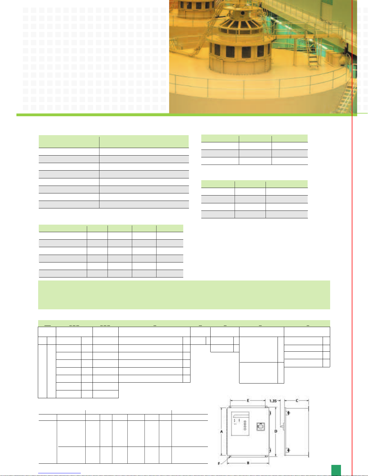
Dime
nsions (inches) Approx. Weight
Unit Options A B C D E F
LM060
LM080
All 16 14 8 16.75 12.0 0.31 35
LM100
LM125
LM150
LM200
LM225 All 20 16 9 21.25 10 0.31 45
LM250
Chart B – LM Series Dimensional Data
How To Specify The Appropriate Model:
All LM model numbers begin with a LM prefix. Use Chart A to build your LM starting with the Surge Rating column. Moving left to right,
choose the correct configurations from each column for your application. Your completed model number should look similar to the example
be
lo
w or LM250120YARCE. Refer to
C
h
art B
f
or LM Se
ries dimensional data.
Standard Monitoring
System, LEDs,
A
u
dible Alarm,
Dual Form C
C
ontacts
LEDs
, Audible
Al
ar
m, Sur
ge
Counter, Dual
Form C Contacts
E
R
T
X
NEMA 12 (Standard)
NEMA 3R
NEMA 4
NEMA 4X
Unit Per Mode Per Phase
060-080
8,000 16,000
100-150 16,000 32,000
200-250
24,000 48,000
Life Cycle Surge Testing 10kA, 20kV, IEEE, Cat. C3
Single Unit Frequency System Installation
34dB 100kHz 51dB
51dB 1MHz 94dB
54dB 10MHz 114dB
48dB 100MHz 120dB
EMI/RFI Noise Rejection
Chart A – Example
Model#
Indicators
Low Cost
Modular
LM
Surge Rating
60kA/mode 060
80kA/mode 080
100kA/mode 100
125kA/mode
125
150kA/mode 150
200kA/mode 200
225kA/mode 225
250kA/mode 250
L - G Voltage
120-120V
208-208V
220-220V
230-230V
240-240V
277-277V
480-480V
600-600V
Configuration
Single Phase L-N, 2W+gnd N
Single Phase L-L, 2W+gnd L
Split Phase, 3W+gnd S
Thr
ee Phase Wye 4W+gnd Y
Three Phase Delta 3W+gnd D
Three Phase Delta Hi-leg 3W+gnd H
Modes of
Protection
ALL A
Connection
Options
WireLug N
Disconnect R
Enc
lo
sur
e
Monitoring Options
Page 5

In today’s world, almost every
business depends on relatively fragile
micro-electronics to run everything
from computer networks to
manufacturing lines. Which means
that power disturbances can disrupt
or cripple equipment, causing the loss
of data, productivity, and money.
In f
act, downtime and damage
caused by dirty power cost North
American companies an estimated
$26 b
i
llion a year.
T
od
a
y
’s in
du
s
tr
i
es are looking for cost-
e
ffective ways to intercept transients,
p
r
o
vi
de c
lean power in their facilities,
an
d s
a
f
egu
ar
d the
ir b
usinesses from the
astronomical, and unnecessary, cost of
d
ir
t
y po
wer. That’s why Liebert
de
si
gned the LM Se
r
i
e
s.
Utilities have generated and distributed
electrical power the same way for decades.
Unfortunately, this unconditioned
electrical power can provide abnormalities
in the electricity that runs in your facility.
This is commonly referred to as “dirty
power.” But until the advent of sensitive
electronic equipment, “clean power”
was never an issue.
What is “Dirty Power?”
5
The causes of dirty power are as
varied as the names used to describe
it — dirty power, electronic rust,
surge, spike, transient, fluctuation,
interruption or noise. Fortunately,
abnormalities typically fall into one of
two categories — external or internal.
Hidden Problems Created
By Dirty Power
n
Unexplained system disruptions.
n
Errors and shutdowns of data
transmission, or scrambled and
unreadable data.
n
Numerous, unexplained server
shutdowns and re-boots.
n
Component failure, often well ahead
of projected life span.
Causes Outside Your Facility
Lightning, natural disasters and
inclement weather can cause hightransient power line voltages that can
adversely affect your power supply.
U
ti
lit
y s
wit
c
hin
g an
d f
aults on the
u
tility’s distribution system can
a
d
v
e
r
sely affect the quality of your
po
w
e
r be
f
or
e it e
v
e
n reaches your
f
acility. Why? Many utility systems are
a
gin
g an
d f
ew power plants
h
a
v
e bee
n b
ui
lt o
v
er the last decade.
With increased demand for power,
the
ir su
p
p
ly margins are dipping
d
an
ge
r
o
u
sl
y lo
w. The farther away
from the source of power, the greater
the r
isk o
f po
w
er quality problems.
Causes Inside Your Facility
According to some studies, 3/4 of all
power disturbances are caused by
equipment inside your building. If
your facility is more then a decade
old, chances are the wiring was not
designed to support the intensive use
of electronic equipment. In industrial
facilities, these problems are even
more complex. In fact, any device that
runs in cycles can create a drain or a
surge when it switches on or off. The
more power the equipment uses, the
bigger the affect. Even something as
small as a copier or a laser printer can
cause problems in sensitive
equipment that share the same line.
The Complete Protection Experts
Of course, you can’t control how
power is distributed. But you can
protect the equipment in your facility
from power surges and transients by
installing equipment such as surge
su
p
p
r
e
s
s
or
s an
d filters. The issues
a
ffecting each industry are varied. In
a
d
d
iti
on t
o the LM Series we offer a
c
om
p
le
t
e ar
r
a
y o
f power conditioning
s
olutions to meet a wide range of
a
p
p
li
cations, locations, and budgets.
Influencing the Industry
Liebert has received the UL 1449
Second Edition rating for the LM
Series. The fact that we’re one of the
first in the industry to receive this
rating is proof that Liebert is leading
the way with our engineering designs
and over 30 years of experience.
Page 6

Emerson Network Power.
The global leader in enabling Business-Critical Continuity
™
.
EmersonNetworkPower.com
AC Power
Connectivity
DC Power
Embedded Computing
Embedded Power
Monitoring
Outside Plant
Power Switching & Controls
Racks & Integrated Cabinets
Services
Precision Cooling
Surge Protection
Liebert Corporation
1050 Dearborn Drive
P.O. Box 29186
Columbus, Ohio 43229
800 877 9222 Phone (U.S. &
Canada Onl
y)
614 888 0246 Phone (Outside U.S.)
614 841 6022
FAX
Via
Leonardo Da Vinci 8
Zona Industriale Tognana
35028 Piove Di Sacco (PD)
Italy
39 049 9719 111 Phone
39 049 5841 257 FAX
Emerson Network Power Asia Pacific
7/F., Dah Sing Financial Centre
108 Gloucester Rd, Wanchai
Hong Kong
852 25722201 Phone
852 28029250 FAX
liebert.com
Technical Support
800 288 6169 Toll-Free
607 724 2484 Phone
607 722 8713 Fax
Ensuring The High Availability Of
Mission-Critical Data And Applications.
Emerson Network Power, the global leader in enabling business-critical continuity,
ensures network resiliency and adaptability through a family of technologies —
cluding Liebert power and cooling technologies — that protect and support
in
business-critical systems. Liebert solutions employ an adaptive architecture that
responds to changes in criticality, density and capacity. Enterprises benefit
from greater IT system availability, operational flexibility, and reduced capital
equipment and operating costs.
usiness-Critical Continuity,
B
©2008 Emerson Electric Co.
rson Network Power and the Emerson Network Power logo are trademarks and service marks of Emerson Electric Co.
Eme
While every precaution has been taken to ensure accuracy and
completeness in this literature, Liebert Corporation assumes no
responsibility, and disclaims all liability for damages resulting
from use of this information or for any errors or omissions.
orporation. All rights reserved throughout
t C
r
be
e
© 2008 Li
orld. Specifications subject to change without notice.
the w
red to are trademarks or registered trademarks
r
e
f
e
s r
ame
All n
espective owners.
ir r
f the
o
® Liebert is a registered trademark of the Liebert Corporation.
A
S
ed in U
t
-22055 (R04/08) Pr
SL
in
 Loading...