

Page 1

KD2 & KD20 Disc Coupling
Installation and Alignment
Instructions
FORM 15-111
APRIL, 2002
KOP-FLEX, INC., P.O. BOX 1696, BALTIMORE MARYLAND 21203, 410-768-2000
KOP-FLEX CANADA, LTD., 19 METEOR DRIVE, REXDALE, ONTARIO, CANADA M9W-1A3, 416-675-7144
!
WARNING
High voltage and rotating parts may cause
serious or fatal injury.
Turn off power to install or service.
Operate with guards in place.
Read and follow all instructions in this manual.
Because of the possible danger to person(s) or property from accidents which may result from the improper use or unapproved modification of the
product, this product must be installed, maintained, and operated in accordance with the procedures, standards and engineering information
specified in the product brochures and illustrations. To assure safe operation, this product should be inspected in accordance with the instructions
described in this form. Proper guards and other suitable safety devices or procedures as may be desirable, or as may be specified in safety codes,
should be installed by the user. Guards and other safety equipment are not provided, nor are they the responsibility of Emerson Power Transmission.
1.0 General Instructions
Prior to installation, inspect the coupling for any signs of damage that may
have occured during shipment. Check that all parts are on hand and are as
ordered.
ONLY BOLTS AND NUTS SUPPLIED BY
KOP-FLEX ARE TO BE USED.
Components should be cradled or supported during handling to avoid damage and should be wrapped for protection. Flanges and pilot surfaces should
be kept free of nicks and burrs.
Read all of the installation instructions and review the procedure before
the actual coupling installation.
2.0 Installation of Coupling Hubs - Keyed Mounting
2.1 Check the hub bore and shaft for nicks and burrs, dress if necessary.
Make sure that the bore and shaft are clean.
2.2 For tapered bores, check the fit of the bore to the shaft.
2.3 Keys must be precisely fitted to the keyways in the shaft and hub.
Each key should have a tight fit on the sides with a slight clearance on
top. To maintain dynamic balance, the keys should fill the keyways
exactly and not be too short or too long.
2.4 Clean the hub bore and shaft. For straight bores, proceed to step 2.6.
For taper bores, mount the hub handtight on the shaft and lightly rap
it with a soft mallet to establish the initial line-to-line fit. This is the
START position. With a depth gauge, measure the amount the hub
overhangs the shaft end and record this value. See Figure 1.
DEPTH GAUGE
Figure 1. Measuring Hub Overhang
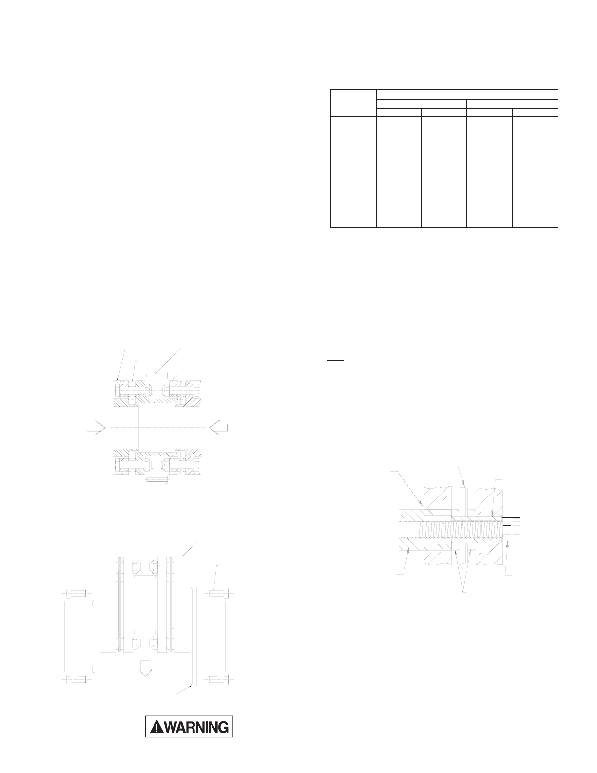
2.5 Taper Bores Only: A recommended method to measure the hub advance is to install a split collar on the shaft, away from the hub by the
amount of the specified advance. Use feeler gauges for accurate spacing. See Figure 2. The amount of hub draw is dependent upon the
desired interference and taper angle as specified by the machine manufacturer or as given on the coupling drawing. See Figure 3.
Advance (in.)
2.6 Heat the hub to expand the bore; DO NOT allow the hub temperature
2.7 Place the hub in the proper position on the shaft. Hold the hub in
Figure 2. Using Split Collar to Set Advance
.070
.060
.050
.040
.030
.020
.010
.000
.0000 .0005 .0010 .0015 .0020 .0025 .0030 .0035 .0040
Figure 3. Hub Advance vs. Interference Chart
to exceed 600°F (300°C). DO NOT apply an open flame to any par t
of the coupling, an oven is recommended.
place as it cools. For taper bores, verify the hub advance (see Figures 1 and 2) and install the shaft retaining nut. Remove the split
collar from the shaft
®
Emerson Power Transmission
FEELER GAUGES
SPLIT COLLAR
Diametral Taper Rate
1/2"/ft
Interference (in.)
To avoid the risk of explosion, fire, or damage to
the coupling and equipment, and/or injury to personnel, do not use an open flame or oil bath to
expand the hub. If heat is used at any time for installation, DO NOT allow the hub temperature to
exceed 600°F (300°C).
5/8"/ft
3/4"/ft
1"/ft
1 1/4"/ft
1 1/2"/ft
.
™
Page 2
3.0 Alignment
Note: Exact values and procedures for aligning equipment are normally
specified by the equipment manufacturers. Good initial alignment to
the minimum possible values will promote optimum machinery performance and eliminate potential operating problems. After securely
tightening the foundation bolts, the hub separation and alignment
should be rechecked and adjusted if necessary.
The coupling alignment should be checked periodically. Even
when a coupling is well aligned at installation, subsequent settling of
foundations, shifting of equipment, etc., may cause the alignment to
deteriorate.
Offset and Angular Alignment
3.1 Reverse dial indication or optical methods of alignment (such as laser) are recommended. A cold alignment and a hot check (with corrections if necessary) are required. The hub flange OD can be used to
mount the alignment equipment. The hub flange OD is machined to
be concentric to the coupling bore and can be used as the reference
diameter.
3.2 The maximum recommended operating misalignment is:
0.10 degrees per disc pack
(0.0035 in/in TIR equivalent parallel offset)
Important: Total misalignment is the combination of equipment parallel offset
Note that improving the alignment below these values will promote
optimum machinery performance.
and angular misalignment.
Axial Alignment
3.3 Align the hubs until they are at the correct hub separation. The hub
separation is measured from the two flange faces, not from the pilot
face.
Hub Separation = Center Assembly Length
4.0 Final Assembly
(KD2 and KD20)
4.1 After correctly installing both hubs, use the separate collapsing screws
to pull the adapter rings toward the center of the pre-assembled center section. This is made up of the spacer, two disc packs, and two
adapter rings.
ADAPTER RING
DISC PACK
COLLAPSING BOLT
SPACER
4.4 Put the center assembly (spacer and rings) between the rigid hubs,
engage the pilot, and install the hub bolts in one hub flange.
4.5 Release all the collapsing bolts, and install the hub flange bolts on the
second rigid hub flange.
4.6 Torque the hub flange bolts to the value specified in Table 1.
gnilpuoC
eziS
301801---351801----
402,30203040507
452,35203040507
403,30357001011051
453,35357001051002
404,304051002072073
454,354051002072073
405----034085
455----046078
406----046078
507----02110051
508----07410002
509----07410002
2DK02DK
bl-tfm-Nbl-tfm-N
)deliOylthgiL(euqroTgninethgiT
Table 1. Flange Bolt Tightening Torques.
5.0 Removal
5.1 Disassemble the coupling in the reverse order as per the applicable
assembly procedure.
5.2 KEYED HUBS - Install a puller on the hub using the tapped holes
provided in the hub face. Pull the hub off the shaft.
6.0 Disc Pack Replacement
The terminology used to identify parts and the order of assembly may differ
from one coupling style to another. Follow the instructions which match the
coupling style being installed.
KD2 - For KD20 skip to 6.7
6.1 Remove the center assembly in reverse order as per the applicable
assembly procedure. Remove disc pack bolts and nuts.
6.2 Insert the disc pack removal socket into one of the clearance holes in
the spacer flange or ring (Figure 6). Install the removal cap screw and
turn it until it cannot be tightened any more.
Note: The removal socket is supplied as part of the “parts kit”.
Figure 4. Collapsing center section
4.2 For each side of the center section, insert the collapsing bolts through
the spacer clearance holes into tapped holes in the ring (see Figure 4).
4.3 Tighten them evenly and collapse the disc packs equally, only enough
to allow the center assembly to drop into place (see Figure 5).
CENTER ASSEMBLY
HUB BOLTS
O.D. PILOT
Figure 5. Installing center section.
Disconnect all power before adjusting units
CLEARANCE HOLE
REMOVAL SOCKET
DISC PACK
BUSHING
REMOVAL SCREW
WASHER
Figure 6. Bolt Disc Pack to Adapter.
6.3 Remove the tool and repeat step 6.2 on all bushings to free the disc
pack from the ring and spacer.
The Emerson logo is a trademark and a service mark of Emerson Electric Co.
© Emerson Power Transmission Manufacturing, L. P. or affiliates 2002. All Rights Reserved.
Page 3

DISC PACK NUT
ADAPTER RING
SPACING WASHER
DISC PACK
DISC PACK BOLT
SPACER
6.4 Line up the bushings of the new disc pack with the reamed holes in
the ring, lightly tap on the bushings to start them into the holes. Insert
3 disc pack bolts and nuts with the
hole, tighten them evenly to pull the bushing into the ring flange (see
Figure 7).
DISK PACK NUT
SPACER
bolt heads in the ring counterbore
DISK PACK
BUSHING
ADAPTER RING
DISK PACK BOLT
Figure 7. Bolt Disc Pack to Adapter Ring.
6.5 Line up the bushings with the spacer reamed holes, lightly tap the
bushings to start them in the holes. Install and tighten 3 disc pack
bolts and nuts
with bolt heads in the ring (see Figure 8).
DISK PACK BOLT
ADAPTER RING
DISC PACK
BUSHING
SPACER
KD20
6.7 Remove the center assembly in reverse order as per the applicable
assembly procedure.
6.8 Unbolt the adapter ring from the disc pack. Unbolt the disc pack from
the spacer.
6.9 Clean and deburr all of the coupling parts.
6.10 Line up the new disc pack between the adapter ring and the spacer.
Insert the disc pack bolt into the counterbored hole in the adapter
ring, and through the disc pack.
6.11 Make sure that the spacer is properly indexed for the large clearance holes to receive the bolt ends. Place the spacing washer and
disc pack nut on the bolt. Repeat for the other bolts (see Figure 9).
Figure 9. Bolt Disc Pack to Adapter Ring.
6.12 Place a spacing washer over a disc pack bolt. Insert the bolt through
the large hole in the adapter ring and through the disc pack bushing
and reamed hole in the spacer. Place the disc pack nut on the bolt.
Repeat for the other bolts (see Figure 10).
ADAPTER RING
SPACING WASHER
DISC PACK
DISC PACK NUT
DISC PACK NUT
Figure 8. Bolt Disc Pack to Spacer.
6.6 Torque all disc pack fasteners evenly and in successive steps to the
value specified in Table 2.
)deliOylthgiL(euqroTgninethgiT
gnilpuoC
eziS
301801---3510304----
402,30205075557
452,352570015557
403,303021061511061
453,353091062571042
404,304092093082083
454,354023034082083
405----024075
455----0370001
406----02010041
507----00810542
508----00320013
509----00320013
2DK02DK
bl-tfm-Nbl-tfm-N
Table 2. Disc Pack Bolt Tightening Torques.
SPACER
DISC PACK BOLT
Figure 10. Bolt Disc Pack to Spacer.
6.13 Torque all disc pack fasteners evenly in successive steps to the
value specified in Table 2.
7.0 Dynamic Balance
Balanced parts will be marked with the letter “B.” The couplings may be
component balanced (hubs and center assembly) with no match marks, or
assembly balanced as a complete coupling with match marks of the hub to
ring connections. If the coupling is supplied with match marks, it must be
assembled with the match marks in line.
Note: For balanced couplings, disconnecting the disc packs from the cen-
ter assemblies disturbs the balance of the coupling. When disc packs
are replaced in balanced couplings, the couplings must be balanced
before placing back in operation.
8.0 Finish Boring and Keyways
Coupling hubs are often furnished with a “rough stock bore.” This rough
bore is not necessarily concentric to other hub diameters. To prepare for
boring, set-up and indicate the hub as shown in Figure 11.
Disconnect all power before adjusting units
© Emerson Power Transmission Manufacturing, L. P. or affiliates 2002. All Rights Reserved.
Page 4

9.0 Bore Sizing and Recommended Fit
The finish bore size should be based on the actual measured shaft dimension, regardless of whether straight or taper shaft. For keyed shafts, a light
interference fit based on a nominal interference rate of 0.0005 inch per inch
of shaft diameter is suggested, or refer to published AGMA standards. Do
not exceed an interference fit of 0.001 inch/inch of shaft diameter. If other
than a light interference fit is desired, consult the published AGMA boring
and keyway standards.
For Straight Bores, the rigid hub diameter should be chucked in the boring lathe and dial indicated as shown of Figure 11. For Taper Bores, chuck
and indicate as shown on Figure 11. Machine the counterbore and SKIM A
REFERENCE DIAMETER on the hub body. Then chuck the hub as shown
on Figure 12, and indicate using the reference diameter before final boring.
Run-outs should be as near zero as possible. It is essential that the finished bore be concentric with the two indicating surfaces.
Figure 11
5 YEAR WARRANTY REGISTRATION CARD
10.0 Keyways
Keyways should be cut to give a tight fit on the sides and slight clearance
over the key. Keyways should not have sharp corners. Refer to published
AGMA standards for specific dimensioning of coupling bores and keyways.
11.0 General Recommendations
11.1 KOP-FLEX KD2 and KD20 disc couplings are designed to operate for
extended periods without the need for lubrication or maintenance. Visual
inspection of the disc packs is sufficient to assess the operational condition
of the coupling.
11.2 All machinery should be monitored to detect unusual or changing vi-
bration levels. KOP-FLEX KD2 and KD20 couplings, under normal conditions, have no wearing parts and will retain their original balance quality.
Any change in vibration levels should be investigated and remedial action
should be taken immediately.
REFERENCE
DIAMETER
Figure 12
Name (Last, First)
Title:
Company Name:
Location:
Phone:
APPLICATION DATA
Coupling Type:
HP:
RPM:
Application:
Shaft Size(s): Driving: Driven:
Distance Between Shaft Ends
Plant Identification Pump # Motor #
Send Warranty Card To: Attention Marketing Department
KOP-FLEX, Inc.
Mail to: P. O. Box 1696 or Fax to: 410-787-8424
Baltimore, MD 21203-1696
Important Safety Instructions
Before start-up . . . for reasons of safety and to extend shaft coupling life,
follow these requirements.
1. Coupling guards protect personnel.
ALL COUPLINGS MUST BE COVERED WITH A GUARD AS PER OSHA REQUIREMENTS.
2. Recheck alignment after all foundation bolts and mechanical connections are tightened.
3. Make sure all fasteners are properly installed and tightened.
4. Take the time to double check your work.
5. Only authorized KOP-FLEX replacement parts are to be used.
6. Call KOP-FLEX for any clarification or questions.
© Emerson Power Transmission Manufacturing, L. P. or affiliates 2002. All Rights Reserved.
®
Emerson Power Transmission
P. O. Box 1696
Baltimore, MD 21203-1696
www.emerson-ept.com
 Loading...