

Emerson Adapt, iTrust Adapt, UHA3R-0200L User Manual

iTrust Adapt UPS 20kVA User
Manual
Emerson Network Power provides customers with technical support. Users may contact the nearest
Emerson local sales office or service center.
Copyright © 2010 by Emerson Network Power Co., Ltd.
All rights reserved. The contents in this document are subject to change witho ut notice.
Emerson Network Power Co., Ltd.
Address: No.1 Kefa Rd., Science & Industry Park, Nanshan District 518057, Shenzhen China
Homepage: www.emersonnetworkpower.com.cn
E-mail: support@emersonnetwork.com.cn
Safety Precauti
ons
This manual contains the information concerning the installation and operation of Emerson iTrust Adapt
/20kVA UPS (hereinafter referred to as UPS). Please
carefully read this manual prior to installation.
The UPS must be installed, commissioned and serviced by engineers designated by the manufacturer or its
agent. Failure to observe this could result in personnel safety risk, UPS malfunction and invalidation of warranty.
The UPS has been designed for commercial and industrial use only, and is not recommended for use in life
support applications.
This is a Class A UPS product. In a residential environment, this product may nevertheless cause radio
interference, in which case, the user may be required to take additional measures.
Conformity And Standards
The UPS complies with 2006/95/EC, 93/68/EEC (LV Safety) and 2004/108/EC (EMC), with Australia and New Zealand EMC
Framework (C-Tick) and with the following product standards for UPS:
* IEC62040-1-1: General and safety requirements for use in operator access area
* IEC62040-2: EMC requirements, Class C2 compliant
* IEC62040-3: Performance requirements and test methods
The UPS installation should follow the above instructions and use the accessories specified by manufacturer.
Warning: High Leakage Current
Earth connection is essential before connecting the input power (AC mains and battery included). This equipment must be
earthed in accordance with the local electrical codes.
Earth leakage current ranges from 3.5mA to 1000mA.
Transient and steady-state earth leakage currents, which may occur when starting the equipment, should be taken into
account when selecting instantaneous residual current circuit breaker (RCCB) or residual current detector (RCD).
RCCB must be selected, which is insensitive to DC unidirectional pulses (Class A) and transient current pulses.
Note that the earth leakage current of the load will be carried by RCCB or RCD.
Warning: Reflected Protection
The UPS has a zero-voltage contact closure signal available for use with an external automatic circuit breaker (single
power), to protect against backfeeding voltage to input terminal through the static bypass circuit. If the installation engineer
do not need to use this signal, the external bypass switchgear must be labelled to advise service personnel that the circuit is
connected to a UPS system.
The label can be written: ISOLATE THE UNINTERRUPTIBLE POWER SYSTEM BEFORE WORKING ON THIS CIRCUIT.
Maintainable Components
All equipment internal maintenance and servicing procedures should be carried out only by trained personnel. Removal of
components behind the protective cover requires the use of a tool and is restricted to service personnel.
The UPS meets the safety requirements completely in operator access area. Only the service personnel can contact with the
hazardous voltage inside the UPS. However, the risk of contacting with these voltages is minimized as the components with
hazardous voltage may be contacted only uses a tool to remove the protective cover. No risk will exist if you follow the
general norms and in accordance with the procedures recommended in this manual on equipment operation.

Battery Voltage Above 400Vdc
Tools or keys must be used for all batteries maintenance, which should be carried out by trained personnel.
Battery use requires special care. After the battery is connected, the voltage of the battery terminal will exceed 400Vdc, and
physical contact would be fatal.
Battery manufacturer provides the precautions to be observed when working on, or in the vicinity of the battery string. These
precautions should be followed implicitly at all times. Particular attention should be paid to the recommendations concerning
local environmental conditions and the provision of protective clothing, first aid and fire-fighting facilities.


Contents
Chapter 1 Product Introduction ........................................................................................................................................... 1
1.1 Feat
ures
................................................................................................................................................................ 1
1.2 Model
Configuration
.............................................................................................................................................. 1
1.3 Appearance And
Components
.............................................................................................................................. 2
1.3.1
Appearance ...............................................................................................................................................
2
1.3.2
Components ..............................................................................................................................................
2
1.4 Operating Principle ............................................................................................................................................... 3
1.5 UPS State And Operation
Mode ...........................................................................................................................
3
1.5.1 Normal
Mode
............................................................................................................................................. 3
1.5.2 Bypass
Mode
............................................................................................................................................. 3
1.5.3 Battery
Mode .............................................................................................................................................
4
1.5.4 ECO Mode (For Single System Only) ........................................................................................................ 4
1.5.5 Fault
State .................................................................................................................................................
4
1.6 S
pec
ificati
ons
........................................................................................................................................................ 5
Chapter 2 Installation .......................................................................................................................................................... 6
2.1 Unpacking I
nspection
............................................................................................................................................ 6
2.2
Location ................................................................................................................................................................
6
2.2.1 Distribution
Room
...................................................................................................................................... 7
2.2.2 Battery
Room
............................................................................................................................................. 7
2.2.3 St
orage
...................................................................................................................................................... 7
2.3 Installation
tools ....................................................................................................................................................
7
2.4 Mechanical Installation.......................................................................................................................................... 8
2.4.1 Tower Installation ...................................................................................................................................... 8
2.4.2 Rack
Installation ........................................................................................................................................
9
2.5 External Protective
Device
.................................................................................................................................. 10
2.5.1 Rectifier And Bypass
Inputting.................................................................................................................
10
2.5.2 Battery
Input ............................................................................................................................................
11
2.5.3 UPS Output ............................................................................................................................................. 11
2.6 Connecting Power Cables .................................................................................................................................. 11
2.6.1 Cables Selection...................................................................................................................................... 11
2.6.2 Connecting I/O
Cables
............................................................................................................................. 12
2.6.3 Connecting Battery
Cables
...................................................................................................................... 17
2.7 Connecting Communication
Cables....................................................................................................................
18
2.7.1 Connecting Dry Contact Communication Cable ...................................................................................... 18
2.7.2 Connecting USB Communication
Cable
.................................................................................................. 19
2.7.3 Connecting SNMP Card Communication
Cable ......................................................................................
19
2.8 Parallel System ................................................................................................................................................... 20

2.8.1 Mechanical Installation ............................................................................................................................ 20
2.8.2 Setting Parallel A
ddresses
....................................................................................................................... 21
2.8.3 Connecting Parallel Cables ..................................................................................................................... 21
2.8.4 Connecting 1 + 1 Parallel POD
Cables....................................................................................................
22
2.9 Shared Batt
ery
.................................................................................................................................................... 22
2.10 Double Bus System .......................................................................................................................................... 23
2.10.1 System Installation ................................................................................................................................ 23
2.10.2 External Protective
Device.....................................................................................................................
23
2.10.3 Power
Cables ........................................................................................................................................
23
2.10.4 LBS Control
Cables
............................................................................................................................... 23
Chapter 3 Operation And Display P
ane
l............................................................................................................................ 24
3.1 Int
roduction
......................................................................................................................................................... 24
3.1.1 LED Indicat
ors
......................................................................................................................................... 24
3.1.2 Audible Alarm (B
uzzer)
............................................................................................................................ 24
3.1.3 Control Butt
ons
........................................................................................................................................ 25
3.1.4 LCD And Menu Butt
ons
........................................................................................................................... 25
3.2 LCD Screen T
ypes
.............................................................................................................................................. 25
3.2.1 Start S
creen
............................................................................................................................................. 25
3.2.2 Primary S
creen
........................................................................................................................................ 26
3.2.3 Default S
creen
......................................................................................................................................... 26
3.3 Detailed Description Of Menu Items ................................................................................................................... 27
3.4 Prompt Wi
ndow
................................................................................................................................................... 29
3.5 UPS Alarm Message List .................................................................................................................................... 29
Chapter 4 UPS Operation Inst
ructions
.............................................................................................................................. 32
4.1 UPS Start
-up
....................................................................................................................................................... 32
4.1.1 Normal Module Start-up P
rocedure
......................................................................................................... 32
4.1.2 Battery Module Start-up
Procedure .........................................................................................................
32
4.2 Transferring Procedures Between Operation
Modes
.......................................................................................... 32
4.2.1 Transferring From Normal Mode To Battery
Mode
.................................................................................. 32
4.2.2 Transferring From Normal Mode To Bypass
Mode..................................................................................
33
4.2.3 Transferring From Bypass Mode To Normal
Mode..................................................................................
33
4.2.4 Transferring From Normal Mode To Maintenance Bypass
Mode ............................................................
33
4.3 Complete Shutdown
Procedure ..........................................................................................................................
33
4.4 EPO P
rocedure
................................................................................................................................................... 34
4.5 Auto
Restar
t ........................................................................................................................................................ 34
4.6 UPS Reset P
rocedure
......................................................................................................................................... 34
4.7 Language
Selection ............................................................................................................................................
34
4.8 Changing Current Date And Time....................................................................................................................... 35
4.9 Controlling P
assword
.......................................................................................................................................... 35

Chapter 5 Maint
enance
..................................................................................................................................................... 36
5.1 Fan
Maintenance ................................................................................................................................................
36
5.2 Battery Maint
enance
........................................................................................................................................... 36
5.3 Cleaning UPS ..................................................................................................................................................... 36
5.4 Checking UPS
State ...........................................................................................................................................
36
5.5 Checking UPS F
unctions
.................................................................................................................................... 36
Appendix 1 Battery
Module ...............................................................................................................................................
38
Appendix 2 Optional Part List ............................................................................................................................................ 40


Chapter 1 Product Introduction
1
Chapter 1 Product Intr
oduction
iTrust Adapt and 20kVA UPS (UPS for short) is an intelligent online UPS system with sine wave output developed by
Emerson Network Power Co., Ltd. The UPS offers reliable and high quality AC power to your precision instrument.
The UPS adopts modular design, and rack/tower installation can be used depending on
your requirements
. It is
applicable to supplying AC power to small scale computer center, network, communication system, automatic control
system and precision instrument.
This chapter gives a brief description of the UPS, including the UPS features, model configuration, appearance,
components, operating principle, state, operation mode and specifications.
1.1 Features
iTrust Adapt UPS is compatible with iTrust Adapt 20kVA UPS. The UPS features include:
•
Compatible with two modes: 3-phase mains output and single-phase mains output. You should check the
system wiring and conduct the panel setting manually
•
Capable of parallel connection to achieve up to 3 + 1 parallel redundant power
•
High-frequency double conversion topology structure, with high input power factor, wide input voltage range, and
output immune to grid interference, thus adaptable to areas with unstable mains supply
•
High power density
•
Full digital control technology based on digital signal processor (DSP) to achieve high system reliability with
self-protection and fault diagnosis functions
•
Intelligent battery management to extend the battery module life
•
Operation and display panel with both LCD and LED indication to help you learn about the system operation
state and operating parameters
•
3U thickness. Tower installation and rack installation are optional to meet different installation requirements
•
Capable of ECO power supply mode, which helps you save energy to the maximum extent
•
Flexible network management with Emerson monitoring software
•
Fan fault self-test and automatic recognition functions
•
SNMP card optional, providing network communication function
•
Capable of connecting multiple battery strings, extending the power supply time of Battery mode
1.2 Model Configuration
The description of model configuration is shown in Table 1-1.
Table 1-1 Model configuration
Model
Description
UHA3R-0200L
For single and parallel 1 + 1 system, four battery modules are available; for parallel system above 1 + 1,
battery connection is required
2
Chapter 1 Product Introduction
iTrust Adapt UPS 20kVA User Manual
1.3 Appearance And Components
1.3.1 Appearance
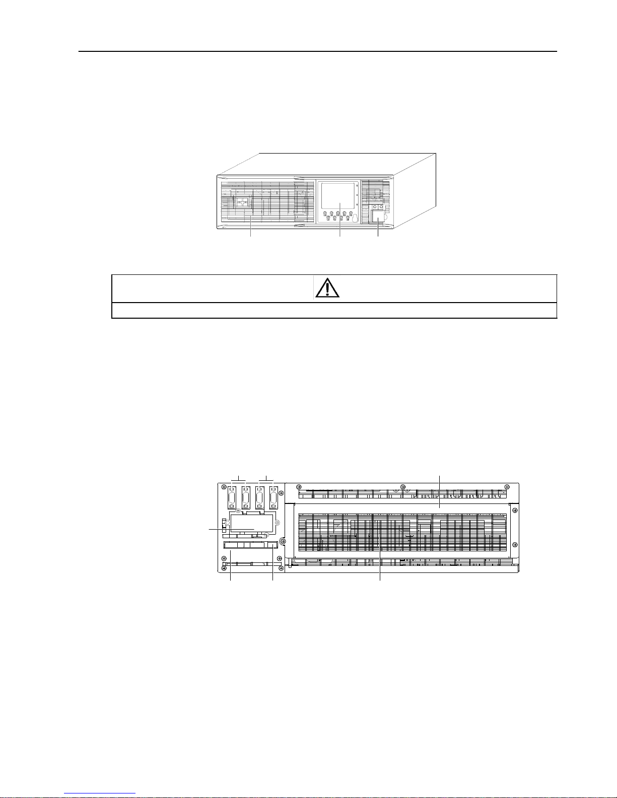
The UPS appearance is shown in Figure 1-1.
Ventilation
holes
Operation
and
display panel
DIP switch, battery cold start
button
(with protective cover)
Figure 1-1 UPS appearance
Note
Non-authorized personnel are prohibited from opening the UPS chassis cover. Otherwise, electric shock may occur.
1.3.2 Components
Front panel
As shown in Figure 1-1, the UPS front panel provides ventilation holes, operation and display panel, DIP switch and
battery cold start button (with protective cover). The operation and display panel provides LCD, menu buttons, LED
indicators and control buttons. Refer to Chapter 3 Operation And Display Panel for details.
Rear panel
As shown in Figure 1-2, the UPS rear panel provides parallel ports, load bus synchronization (LBS) ports, dry contact
I/O port, SNMP card port, USB port, I/O terminal block and ventilation holes.
Parallel ports
LBS ports
I/O terminal block (with protective cover)
SNMP card
port
(with
protective cover)
Dry contact I/O port USB port
Ventilation
holes
Figure 1-2 UPS rear panel
Chapter 1 Product Introduction
3
1.4 Operating Principle
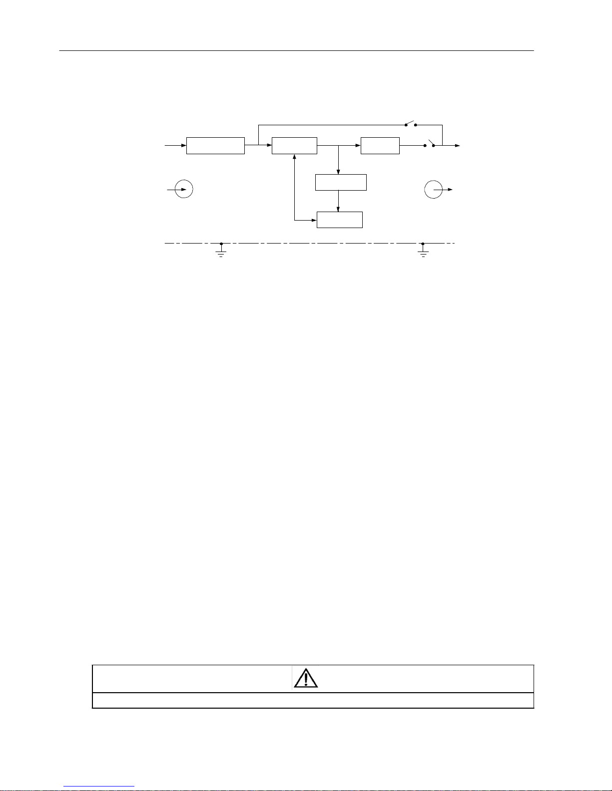
The operating principle of the UPS is shown in Figure 1-3.
Bypass
I/O filter
Rectifier/PFC
Inverter
Mains
DC/DC charger
Output
Battery
GND GND
Figure 1-3 Operating principle
1. The UPS is composed of mains input, I/O filter, rectifier/PFC, DC/DC charger, inverter, bypass, battery and UPS
output.
2. When the mains is normal, the rectifier will start, and the DC/DC charger will charge the battery string. Before
turning on the UPS, the output voltage is the bypass voltage. After turning on the UPS, the electronic transfer switch
connects the inverter output to the load, and the mains supplies DC power to the inverter through the rectifier/PFC
circuit. The inverter then converts DC power into pure sine wave AC power, and supplies AC power to the load
through the electronic transfer switch.
3. When the mains is abnormal, the rectifier/PFC circuit boosts the battery voltage and supplies it to the inverter. The
inverter then converts it into pure sine wave AC power, and supplies AC power to the load through the electronic
transfer switch.
4. After the mains returns to normal state, the UPS will automatically transfer from Battery mode to Normal mode, the
mains power supplies DC power to the inverter through the rectifier/PFC circuit, and then the electronic transfer
switch supplies DC power to the load.
1.5 UPS State And Operation Mode
The UPS state and operation mode include: Normal mode, Bypass mode, Battery mode, ECO mode and Fault state.
For the indicators introduced in this section, refer to Chapter 3 Operation And Display Panel.
1.5.1 Normal Mode
When the mains input is normal, the load is powered with voltage-stabilizing and frequency-stabilizing power by the
mains after processing of the rectifier and the inverter, and meanwhile, the operation mode that the charger charging
the battery is the Normal mode. In Normal mode, the inverter indicators are on (green).
1.5.2 Bypass Mode
If the overload overtime, inverter or rectifier failure appear during the UPS operation in Normal mode, the UPS will
transfer to Bypass mode, that is, the load is powered by the bypass source, which comes directly from the mains
input; if the rectifier is normal, the internal charger will charge the battery. In Bypass mode, the inverter indicators are
off.
Note
In the event of mains failure or mains voltage out of range in Bypass mode, the UPS will shut down and stop the output.

4
Chapter 1 Product Introduction
iTrust Adapt UPS 20kVA User Manual

Chapter 1 Product Introduction
5
1.5.3 Battery Mode
Upon mains failure, rectifier overload or mains voltage out of range, the rectifier and internal charger will become
inoperative, and the battery will supply power to the load through the inverter. The inverter indicators are on together
with buzzer alarming, which notifies you that the UPS is in Battery mode.
Note
1. The battery has been fully charged before delivery. However, transportation and storage will inevitably cause some capacity
loss. Therefore, it is required to charge the battery for eight hours before putting the UPS into operation, so as to ensure the
adequate stand time for battery.
2. The battery cold start can also be used to start the UPS from the Battery (charged) mode upon mains failure. Therefore, the
battery power can be used independently for improving the system availability to some extent.
1.5.4 ECO Mode (For Single System Only)
In ECO mode, the load is powered by bypass when the bypass voltage is normal, and the load is powered by inverter
when the bypass voltage is abnormal. ECO mode is an energy-saving operation mode. For some power equipment
that insensitive to power grid quality, you can use the ECO mode for power supply through bypass to reduce the
power loss.
Note
1. In ECO mode, if the bypass failure or abnormal bypass voltage appears when the output is not overloaded, the UPS will transfer
to Normal mode. However, if the bypass failure or abnormal bypass voltage appears when the output is overloaded, the UPS will
not transfer to Normal mode, but shut down the bypass.
2. In ECO mode, the efficiency of the UPS is up to 98%.
1.5.5 Fault State
In Normal mode, the UPS will transfer to Bypass mode if the inverter failure or UPS overtemperature appears. In
Battery mode, the UPS will shut down and stop the output if the inverter failure or UPS overtemperature appears. In
Fault state, the fault indicators will turn on, the buzzer will keep beeping, and the corresponding fault information will
be displayed on LCD panel.
Note
In Fault state, if the bypass failure or abnormal bypass voltage appears when the output is not overloaded, the UPS will shut down
and be transfered to the inverter for power supply, such as radiator overheat. However, if the bypass failure or abnormal bypass
voltage appears when the output is overloaded, the UPS will not be transfered to the inverter for power supply, but shut down the
bypass.

6
Chapter 1 Product Introduction
iTrust Adapt UPS 20kVA User Manual
1.6 Specifications
The UPS specifications are listed in Table 1-2.
Table 1-2 UPS specifications
Product model
UHA3R-0200L
Input
Rated voltage
3-phase: 380Vac
Voltage range
304Vac ~ 478Vac, at full load
228Vac ~ 304Vac, linear derating
228Vac, at half load
Rated frequency
50Hz/60Hz
Frequency range
40Hz ~ 70Hz
Power factor
≥0.99, at full load; ≥0.98, at half load
Output
Rated power
18kW
Voltage
220Vac ± 1% (3-phase balance load)
Frequency sync range
Rated frequency ± 2Hz (range is settable: ±0.5Hz ~ ±3Hz)
Frequency track rate
1Hz/s. Range is settable: 0.1Hz/s ~ 3Hz/s (single), 0.2Hz/s (parallel)
Rated power factor
0.9
Crest factor
3:1
Voltage harmonic
distortion
<2% (linear load), <5% (non-linear load)
Dynamic response
recovery time
60ms
Overload capacity
105% ~ 125%, 5min
125% ~ 150%, 1min
Bypass voltage
Upper limit: +10%, +15% or +20%; default: +15%
Lower limit: -10%, -20%, -30% or -40%; default: -20%
Mains efficiency
>93%, up to 94%
Battery
Type
Sealed, lead-acid, maintenance-free battery
Cell No.
30, 32, 34, 36, 38, 40
Rated voltage
360Vdc ~ 480Vdc
Charge power
4.5kW
Transfer time
Mains←→Battery
0ms
Inverter←→Bypass
Synchronous transfer: ≤1ms
Asynchronous transfer (default): ≤20ms
Or 40ms, 60ms, 80ms and 100ms are available
Noise
≤58dB
Panel display mode
LED and LCD
Safety
IEC/EN62040-1-1
EMC
Conduction emission
IEC/EN62040-2
Immunity
I≤16A
,
IEC/EN61000-3-3; 16A<I≤75A, IEC/EN61000-3-11
Harmonic current
I≤16A,IEC/EN61000-3-2; 16A<I≤75A, IEC/EN61000-3-12;
YD/T1095-2001, level 2
,
15%
Surge protection
IEC/EN-61000-4-5, enduration level 4 (4kV) (live line to earth), level 3 (2kV)
(during live lines)
Protection level
IP20
Ambient
condition
Operating temperature
0°C ~ +40°C
Storage temperature
-40°C ~ +70°C (battery excluded); -20°C ~ +55°C (battery included)
Relative humidity
5%RH ~ 95%RH, non-condensing
Altitude
<2000m; derating in accordance with GB/T3859.2 when higher than 2000m
Size
W × H × D
435mm × 130mm × 750mm
Weight
Net weight
35kg
Gross weight
38kg

 Loading...