

Page 1
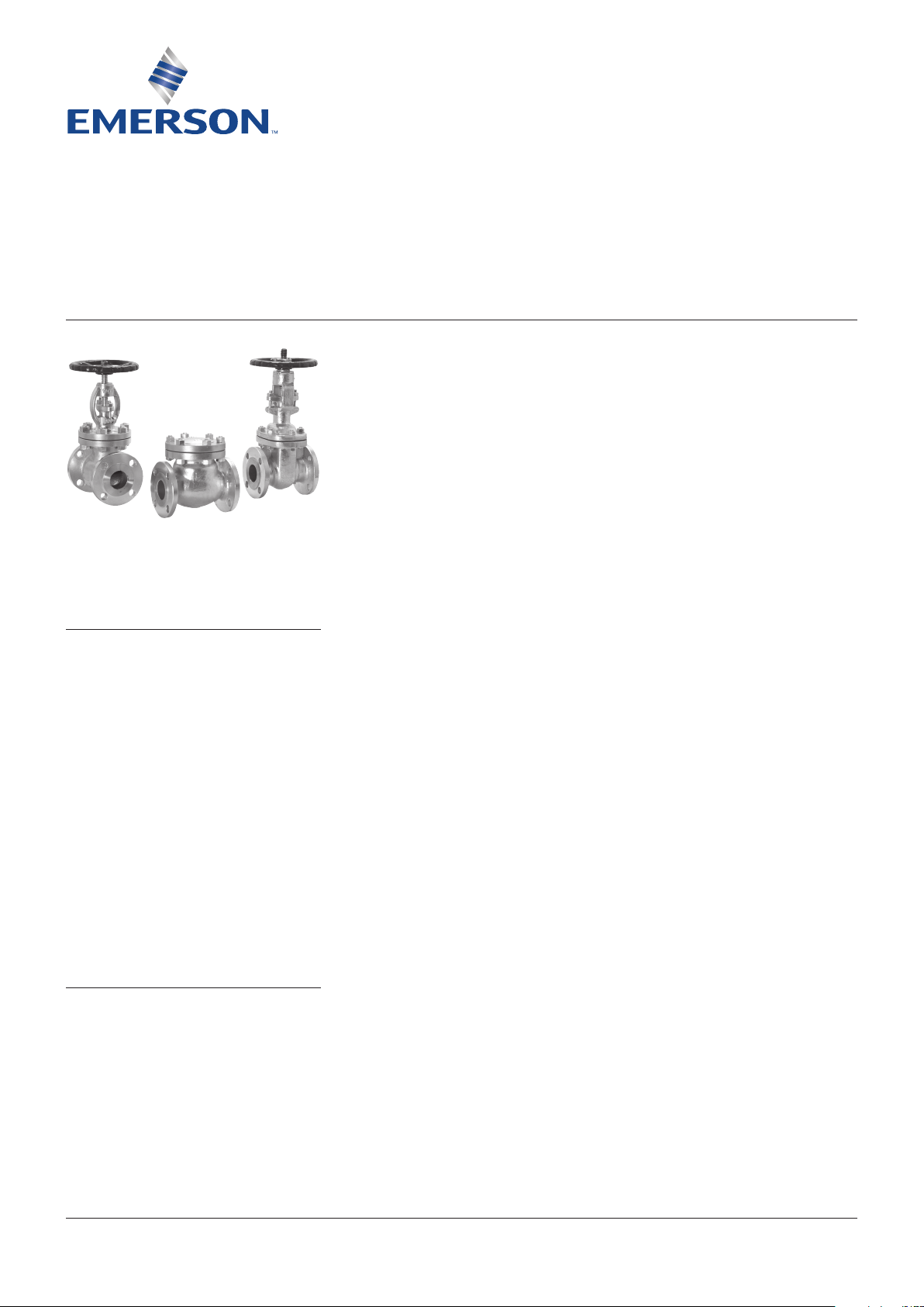
HANCOCK CAST STEEL - GATE, GLOBE AND CHECK VALVES
INSTALLATION, OPERATION AND MAINTENANCE INSTRUCTIONS
Before installation these instructions must be fully read and understood
1.2 Inspection
Before carrying out a valve installation, it is
important to determine whether the valve is in
asatisfactory condition.
The following generally applicable procedure
may be helpful in avoiding subsequent valve
problems and should be observed.
a) Carefully unpack the valve and check tags,
identification plates, direction of rotation
of handwheels etc, against bill of material,
specifications, schematics etc.
b) Make a point of noting any special warning
Instructions for DN 50 - 600 (NPS 2 - 24)
ASMEclass 150, 300 and 600 bolted bonnet
caststeel valves.
SAFETY NOTICE
It is essential that a safe system of work
should be adopted before any maintenance
work is done on a valve. The following safety
considerations should be taken in to account
when preparing maintenance instructions.
Before removing valves from a pipework
system or dismantling a valve to carry out
maintenance, it will be necessary to open,
or partially open, the valves and to flush the
system to remove all traces of dangerous
fluidsand pressures.
It is important to recognize the danger
associated with the removal of the stem
packing gland with pressure in the pipework
system and the use of the backseat should not
be regarded as a device permitting repacking
of the stem packing gland whilst the valve
is under pressure as this is recognized as
dangerous practise.
tags or plates attached to or accompanying
the valve, and take any appropriate action.
c) Check the valve for any marking indicating
flow direction. If the flow direction is
indicated, appropriate care should be
exercised to install the valve for proper
flowdirection.
d) As far as is practicable, inspect the valve
interior through the end ports to determine
whether it is reasonably clean, free from
foreign matter and harmful corrosion.
Remove any special packing materials,
such as blocks used to prevent disk
movement during transport and handling,
and anti-corrosion packs. Wipe clean from
preservation coatings, particularly seatings.
e) If practicable, cycle the valve through open
and close. Check guides or seat faces, etc.
f) Immediately prior to valve installation,
check the pipework to which the valve is
tobe fastened for cleanliness and freedom
from foreign materials.
1 GENERAL INSTALLATION INSTRUCTIONS
1.1 General
The installation procedure is a critical stage in
the life of a valve and care should be taken to
avoid damaging the valve.
© 2017 Emerson. All Rights Reserved.Emerson.com/FinalControl VCIOM-02504-EN 19/04
Page 2
HANCOCK CAST STEEL - GATE, GLOBE AND CHECK VALVES
INSTALLATION, OPERATION AND MAINTENANCE INSTRUCTIONS
1.3 Flanged joint assembly
Pipe flanged joints depend on compressive
deformation of gasket material between the
facing flange surfaces for tight sealing.
In order to obtain satisfactory flange joints,
thefollowing points should be observed.
a) Check the mating flange facings (both valve
and pipework flanges) for correct gasket
contact face, surface finish and condition.
b) Check the bolting for proper size, length
and material. A carbon steel bolt on a high
temperature flange joint can result in early
joint failure.
c) Check the gasket material. For flange joints
using low strength bolting, such as may be
provided for iron flanges, metal gaskets
(flat, grooved, jacketed, corrugated or spiral
wound) should not be used.
d) Check the gaskets for freedom from defects
or damage.
e) Take care to provide good alignment of
the flanges being assembled. Use suitable
lubricants on bolt threads. In assembly,
sequence bolt tightening to make the initial
contact of flanges and gaskets as flat and
parallel as possible. Tighten gradually and
uniformly to avoid the tendency to twist one
flange relative to other.
f) Parallel alignment of flanges is especially
important in the case of the assembly of a
valve in to an existing system. It should be
recognized in such instances that, if the
flanges are not parallel, it will be necessary
to introduce bending to make the flange
joint tight. Simply, forcing the flanges
together with the bolting may bend the pipe,
or it may bend the valve.
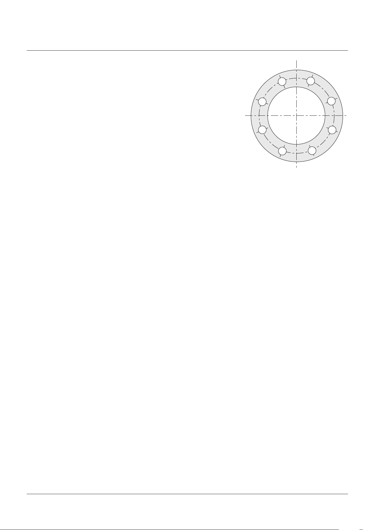
g) All bolts shall be tightened in a star
pattern as shown below to ensure uniform
gasketloading.
1.4 Butt weld joint assembly
All welding should comply with the appropriate
pipe system or application code. Welded
joints, properly made, provide a structural
andmetallurgical continuity between the
pipeand the valve body.
Butt welds require full penetration and
thickness at least equal to that of the pipes.
If a pipe of high strength alloy is welded to a
valve with body material of lower mechanical
strength, the weld should taper to a
compensating greater thickness at the valve
end, or the valve should have a matching high
strength welded-on extension.
Particular care is necessary when welding
valves into the line. Considerable distortion,
resulting in line strains, may occur if valves
are not welded into the line with care, where
required, the weld properly stress relieved,
but it is necessary to ensure that such stress
relieving does not result in valve components,
particularly the seatings being subjected to
unacceptable temperatures.
It is recommended that the valves are not
installed in the pipework at points of high
bending moments, as this can adversely
affectthe seating performances.
1.5 Testing and adjustment
Following installation, all valves should
be operated to check that they still
functioncorrectly.
On new pipework systems, system pressure
testing and commissioning follow after
installation when various checks are made.
Valves are usually supplied in the lubricated
condition, but it is recommended that checks
are made to ensure that this is still intact,
particularly after the application of heat
(e.g.welding operation).
A first observation can be made by actuating
the valve through an open-close or
close-opencycle.
It is common practice, after installation of
pipework systems, to clean the system by
blowing with a gas or steam or flushing with
a liquid to remove debris and / or internal
protective films and coatings. It should be
recognized that valve cavities may form a
natural trap in a pipework system and material
not dissolved in or carried out by the flushing
fluid may settle in such cavities and adversely
affect valve operation. Also, abrasive material
carried by a high velocity fluid stream may
cause serious damage to seating surfaces.
Do not subject the valve to pressures/
temperature testing in excess of its
statedlimits.
1
8
4
6
BOLT TORQUING SEQUENCE
1-2-3-4-5-6-7-8
5
3
7
2
2
Page 3
HANCOCK CAST STEEL - GATE, GLOBE AND CHECK VALVES
INSTALLATION, OPERATION AND MAINTENANCE INSTRUCTIONS
2 GATE VALVES
2.1 Installation and operation
2.1.1 Prior to installation
Valves not required for immediate use should
be stored under clean conditions to reduce the
risk of foreign matter entering the valve during
unpacking. If the valves are unpacked for
checking purposes, they should be immediately
re-packed until required for use.
Protection caps fitted to inlet and outlet
connections must be removed, but not until
immediately prior to installation.
Seating faces should be wiped clean with a
drycloth before commencing installation.
2.1.2 Installation
Valves are suitable for flow in either direction,
but they should be fitted in either horizontal
pipelines with the stem upright or vertical
lines. Other positions can be detrimental to
theproper seating of the wedge.
The valves should be installed in positions
where the minimum stress is imposed on them
from expansion and contraction of the pipe, and
pipework should be adequately supported close
to the valve to minimize mechanical pipe strain.
For bolting valves into the pipeline, see General
Installation Instructions Section 1.
All valves will have been pressure tested at
ambient temperature before delivery, so it is
recommended that gland packing nuts should
be tightened after a short time on higher
temperature service.
2.1.3 Operation
Rotation of the handwheel in the clockwise
direction (see markings) will cause the valve
to close, and vice versa. Shut off should be
achieved by application of the handwheel torque
only. Excessive application of force can result in
failure of the thrust assembly or damage to the
valve seating.
2.2 Maintenance
Gland leakage
CAUTION
On no account should stem gland repacking be
attempted under pressure if the contained fluid is
dangerous because of temperature, high pressure
or chemical composition.
Evenly tighten the gland adjusting nuts to
compress the packing rings.
If this does not correct the leakage or if
the adjustment is fully used up, it will be
necessaryto repack the gland using a new
set of the correct grade packing, or to add
packingring(s).
Re-packing glands
To gain access to the packing box, the gland
adjusting nuts should be removed and the
gland and packing flange removed or retracted
along the stem as far as possible. When the
stuffing box has been completely emptied of the
original packing, it must be thoroughly cleaned
before the new packing is introduced. It is
recommended that the packing manufacturers
general instructions are followed when
repacking glands.
General
It is recommended that the reconditioned valve
should be subjected to hydrostatic testing in
line, before being reinstated on line working
conditions.
2.3 Spares
The normal requirement for spare parts for
normal wear in service are gland packing
andgaskets.
20
19
18
14
11
10
05
08
04
02
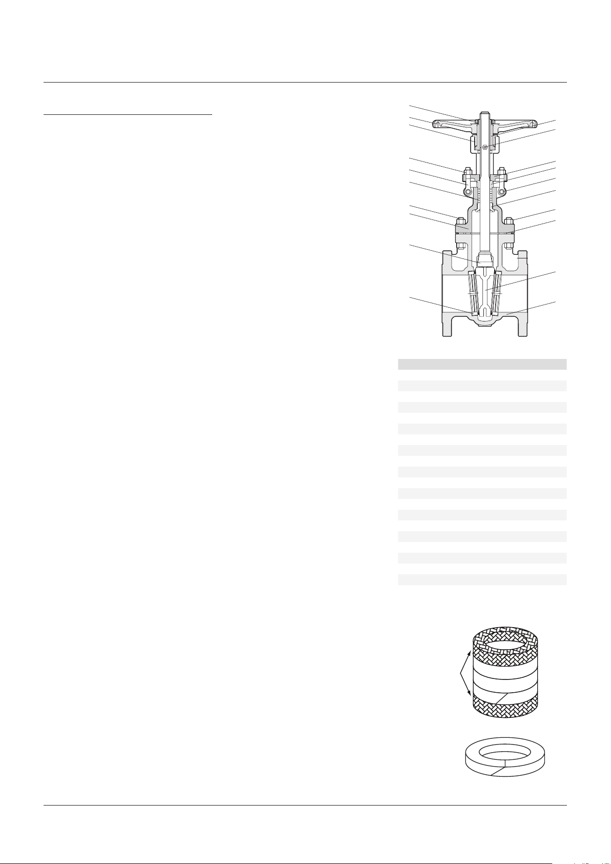
PARTS LIST
No. Description
1 Body
2 Seat ring
3 Wedge gate
4 Stem
5 Bonnet bolt
6 Bonnet nut
7 Gasket
8 Bonnet
9 Backseat
10 Packing
11 Gland eyebolt
12 Gland
13 Gland flange
14 Eyebolt nut
15 Eyebolt pin
16 Nipple
17 Stem nut
18 Yoke sleeve nut
19 Hand wheel
20 Hand wheel nut
17
16
13
12
15
09
06
07
03
01
Braided end ring
Die-formed rings
(3 min.)
Braided end ring
120° Stagger of joints
45° End cut
3
Page 4
19
HANCOCK CAST STEEL - GATE, GLOBE AND CHECK VALVES
INSTALLATION, OPERATION AND MAINTENANCE INSTRUCTIONS
3 GLOBE VALVES
3.1 Installation and operation
3.1.1 Prior to installation
Valves not required for immediate use should
be stored under clean conditions to reduce the
risk of foreign matter entering the valve during
unpacking. If the valves are unpacked for
checking purposes, they should be immediately
re-packed until required for use.
Protection caps fitted to inlet and outlet
connections must be removed together with
any internal anti-corrosion sachets, but not
until immediately prior to installation.
3.1.2 Installation
Valves are suitable for flow in one direction only
(as indicated on the body) and must be installed
accordingly. They should be installed with the
stem in either the upright or horizontal position.
Other positions may be detrimental to the
proper seating of the disk.
The valves should be installed in positions
where minimum stress is imposed on them
from expansion and contraction of the pipe, and
pipework should be adequately supported close
to the valve to minimize mechanical pipe strain.
All valves will have been pressure tested at
ambient temperature before delivery so it is
recommended that gland packing nuts should
be tightened after a short time on higher
temperature service.
3.1.3 Operation
Rotation of the handwheel in the clockwise
direction (see marking) will cause the valve
toclose, and vice versa.
Excessive force application other than by the
handwheel can result in failure of the thrust
assembly or damage to the valve seating.
3.2 Maintenance
Routine maintenance
While the valve is working satisfactorily,
the only requirement for routine service is
lubrication of the thrust assembly.
Valves are supplied with this assembly fully
lubricated and should operate smoothly.
To avoid problems from developing, the
assembly should be regularly lubricated on
thestem.
Recommended grade of grease is:
MobuluxEP2 (or equivalent).
Gland Leakage
CAUTION
On no account should stem gland repacking be
attempted under pressure if the contained fluid is
dangerous because of temperature, high pressure
or chemical composition.
Evenly tighten the gland adjusting nuts to
compress the packing rings.
If this does not correct the leakage or if the
adjustment is fully used up, it will be necessary
to repack the gland using a new set of the
correct grade packing, or to add packingring(s).
Re-packing glands
To gain access to the packing box, the gland
adjusting nuts should be removed and the
gland and packing flange removed or retracted
along the stem as far as possible. When the
stuffing box has been completely emptied of the
original packing, it must be thoroughly cleaned
before the new packing is introduced. It is
recommended that the packing manufacturers
general instructions are followed when
repacking glands.
General
It is recommended that the reconditioned valve
should be subjected to hydrostatic testing
in-line, before being reinstated on line working
conditions.
3.3 Spares
The normal requirement for spare parts for
normal wear in service are gland packing
andgaskets.
18
15
14
11
09
07
06
03
02
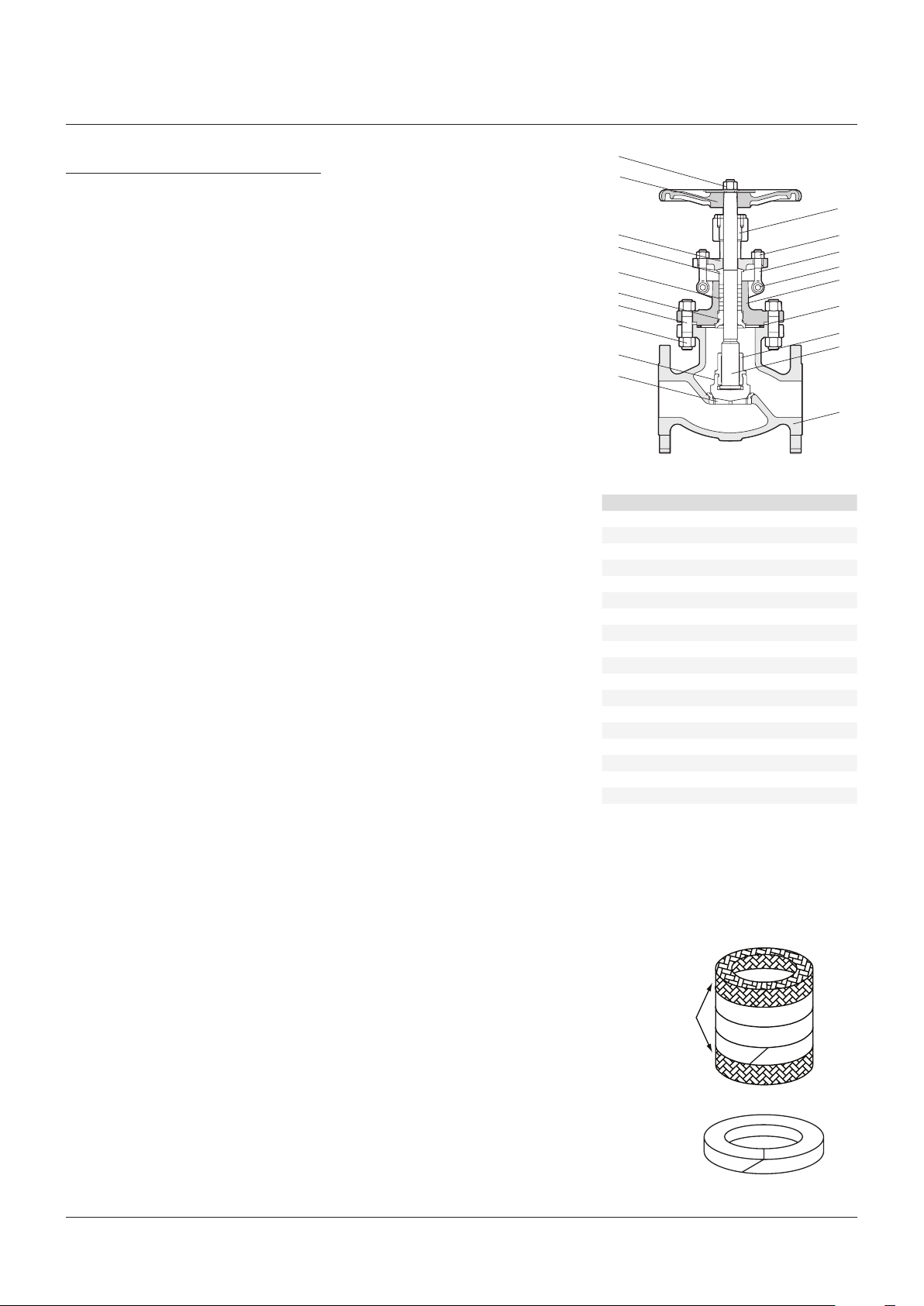
PARTS LIST
No. Description
1 Body
2 Seat ring
3 Disc
4 Stem
5 Disc nut
6 Bonnet nut
7 Bonnet stud
8 Gasket
9 Backseat
10 Bonnet
11 Packing
12 Eyebolt pin
13 Gland eyebolt
14 Gland
15 Gland flange
16 Eyebolt nut
17 Stem nut
18 Hand wheel
19 Hand wheel nut
17
16
13
12
10
08
05
04
01
Braided end ring
Die-formed rings
(3 min.)
Braided end ring
120° Stagger of joints
45° End cut
4
Page 5
HANCOCK CAST STEEL - GATE, GLOBE AND CHECK VALVES
INSTALLATION, OPERATION AND MAINTENANCE INSTRUCTIONS
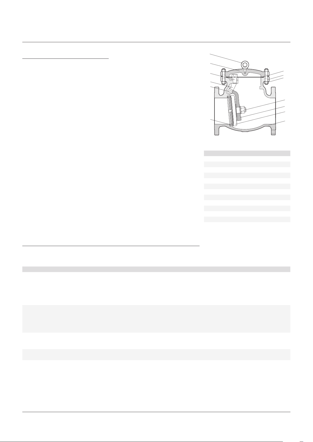
4 SWING CHECK VALVES
4.1 Installation of valve
4.1.1 Prior to installation
Valves not required for immediate use should
be stored under clean conditions to reduce the
risk of foreign matter entering the valve during
unpacking. If the valves are unpacked for
checking purposes, they should be immediately
re-packed until required for use.
Protection caps fitted to inlet and outlet
connections must be removed but not until
immediately prior to installation.
Check that the disk is swinging freely on its
hinge arrangement with no hang-ups.
Seating faces should be wiped clean with a dry
clean cloth before commencing installation.
4.1.2 Installation
Valves are suitable for flow in one direction only
and this is shown by a direction arrow marked
on the valve body. It is essential that they are
installed in the correct flow (arrow) situation.
They may be fitted in horizontal or vertical
(flow-upwards) pipelines, or any in-between
lines with flow-upward. They must always be
orientated so that the hinge swings downwards
and with the hinge pin horizontal.
The valves should be installed in positions
where the minimum stress is imposed on them
from expansion and contraction of the pipe,
and pipe work should be adequately supported
each side of the valve to minimize mechanical
pipestrain.
4.2 Maintenance
Routine Maintenance
While the valve is working satisfactory, there
isno requirement for servicing.
13
12
10
07
06
02
PARTS LIST
No. Description
1 Body
2 Seat ring
3 Disc
4 Lever arm
5 Nut
6 Hinge pin
7 Yoke
8 Bonnet nut
9 Bonnet stud
10 Bolt
11 Gasket
12 Cover
13 Eye bolt
11
9
8
05
04
03
01
5 TROUBLE-SHOOTING
The following table will cover the various problems which are common to most valves.
Theinformation provided will aid in isolating and correcting these problems.
Problem Possible cause Solution
Leakage through
thestempacking
Problems in operating
valve
Bonnet leakage 1. Bonnet nuts are loose. 1. Tighten to values as listed.
Seat leakage 1. Valve not properly seated.
1. Gland nuts are loose. 1. Tighten gland bolts.
2. Gland is binding against the stem or packing chamber wall. 2. Check to ensure gland is centered and evenly tightened.
3. Inadequate amount of packing rings. 3. Install additional packing rings.
4. Packing is hard and dry. 4. Replace with new packing.
5. Packing was not properly cut and staggered. 5. Replace with new packing.
6. Stem is damaged. 6. Repair or replace as required.
1. Stem binding during travel. 1. Remove dirt and lubricate stem with grease.
2. Stem packing is exerting excessive force on the stem. 2. Check torque on gland nuts.
3. Stem is damaged. 3. Examine stem through full open and close action.
Repairorreplaceasrequired.
4. Internal components may be damaged. 4. Disassemble the valve. Inspect and repair as needed.
2. Gasket is damaged. 2. Disassemble and install a new gasket.
3. Flange faces are damaged. 3. Repair and install a new gasket.
1. Check to see if valve is tightly closed.
2. Internal components are damaged or worn.
2. Inspect internal components and repair as required.
5
Page 6

HANCOCK CAST STEEL - GATE, GLOBE AND CHECK VALVES
INSTALLATION, OPERATION AND MAINTENANCE INSTRUCTIONS
6 TORQUE VALUES FOR BONNET BOLTING
Torque
Bolt nominal diameter (in)
½ 61 45
9
⁄
16 88 65
⅝ 118 87
¾ 206 152
⅞ 328 242
1 488 360
1⅛ 725 533
1¼ 1017 750
1⅜ 1383 1020
1½ 1627 1200
1⅝ 2237 1650
1¾ 3051 2250
1⅞ 4068 3000
2 4475 3300
NOTES
1. Values are for B7 bolting only. For other materials please consult Hancock.
2. Values listed are based on 45000 psi bolting stress, lubricated with heavy graphite/oil mixture.
Non lubricated bolts have an efficiency of 50% ofthe values stated above.
3. All bolts should be torqued in the bolting sequence shown above to ensure uniform bonnet gasketloading.
(Nm) (ft·lb)
Neither Emerson, Emerson Automation Solutions, nor any of their affiliated entities assumes responsibility for the selection, use or maintenance of any product.
Responsibility for proper selection, use, and maintenance of any product remains solely with the purchaser and end user.
Hancock is a mark owned by one of the companies in the Emerson Automation Solutions business unit of Emerson Electric Co. Emerson Automation Solutions,
Emerson andthe Emerson logo are trademarks and service marks of Emerson Electric Co. All other marks are the property of their respective owners.
The contents of this publication are presented for informational purposes only, and while every effort has been made to ensure their accuracy, they are not to be
construed as warranties or guarantees, express or implied, regarding the products or services described herein or their use or applicability. All sales are governed by
our terms and conditions, which are available upon request. We reserve the right to modify or improve the designs or specifications of such products at any time without
notice.
Emerson.com/FinalControl
6
 Loading...