

Page 1

EV3200 Door Control Inverter
User Manual
Version V1.4
Revision date April 21, 2008
BOM
31011543
Emerson Network Power provides customers with technical support. Users may contact the nearest
Emerson local sales office or service center.
Copyright © 2007 by Emerson Network Power Co., Ltd.
All rights reserved. The contents in this document are subject to change without notice.
Emerson Network Power Co., Ltd.
Address: No.1 Kefa Rd., Science & Industry Park, Nanshan District 518057, Shenzhen China
Homepage: www.emersonnetworkpower.com.cn
Customer Service Hotline: +86 755 86010537, 400-887-6510
Complaint Hotline: +86 755 86010800
E-mail: support@emersonnetwork.com.cn
Page 2

Contents
Chapter 1 Safety Information ..............................................................................................................................................1
1.1 Warnings, Cautions & Notes................................................................................................................................. 1
1.2 Electrical Safety - General Warning ...................................................................................................................... 1
1.3 System Design And Safety Of Personnel .............................................................................................................1
1.4 Motor..................................................................................................................................................................... 1
1.5 Adjusting Parameters............................................................................................................................................ 1
1.6 Electrical Installation ............................................................................................................................................. 1
1.6.1 Electric Shock Risk.................................................................................................................................... 1
1.6.2 Isolation Device ......................................................................................................................................... 1
1.6.3 STOP Function .......................................................................................................................................... 2
1.6.4 Stored Charge ........................................................................................................................................... 2
1.6.5 Equipment Supplied By Plug And Socket .................................................................................................. 2
1.6.6 Earthing Requirement................................................................................................................................ 2
1.6.7 Capacitor And Varistors............................................................................................................................. 2
1.7 Disposing Of Unwanted Inverter ........................................................................................................................... 2
Chapter 2 Product Specifications ........................................................................................................................................ 3
2.1 Model Description ................................................................................................................................................. 3
2.2 Nameplate ............................................................................................................................................................ 3
2.3 Models .................................................................................................................................................................. 3
2.4 Installation Size..................................................................................................................................................... 4
2.5 Specifications........................................................................................................................................................ 4
Chapter 3 Electrical Installation........................................................................................................................................... 6
3.1 Wiring Of Power Terminals ................................................................................................................................... 6
3.1.1 Introduction To Power Terminals............................................................................................................... 6
3.1.2 Connection Of Power Terminals................................................................................................................ 7
3.2 Control Terminals.................................................................................................................................................. 8
3.3 User Relay Output Terminals................................................................................................................................ 8
3.4 PG Terminals Of Synchronous Motor ................................................................................................................... 9
3.5 Wiring Diagram Of Inverter ................................................................................................................................... 9
3.6 EMC.................................................................................................................................................................... 10
Chapter 4 Operation.......................................................................................................................................................... 12
4.1 Operation ............................................................................................................................................................ 12
4.1.1 Operation Keypad.................................................................................................................................... 12
4.1.2 Description Of Inverter Operating Status ................................................................................................. 12
4.1.3 Description Of Inverter Operating Mode .................................................................................................. 12
4.1.4 Parameter Classification.......................................................................................................................... 13
4.1.5 Parameter Setting Method....................................................................................................................... 13
Page 3

4.1.6 Display Of Parameters............................................................................................................................. 13
4.2 Basic Applications............................................................................................................................................... 13
4.2.1 Motor Tuning ........................................................................................................................................... 13
4.2.2 Basic Operating Modes ...........................................................................................................................14
Chapter 5 Parameter Table............................................................................................................................................... 15
5.1 Basic Operation Parameters F0.......................................................................................................................... 15
5.2 OD Operation Parameters F1 ............................................................................................................................. 15
5.3 CD Operation Parameters F2 ............................................................................................................................. 16
5.4 Enhanced Function Parameters F3 .................................................................................................................... 16
5.5 Door Width Self-learning Parameters F4 ............................................................................................................ 17
5.6 Multi-function Input Terminal Parameters F5 ...................................................................................................... 18
5.7 Motor Parameters F6 .......................................................................................................................................... 18
5.8 Vector Control Parameters F7 ............................................................................................................................ 19
5.9 Communication Parameters F8 (Reserved)........................................................................................................ 19
5.10 Monitoring And Recording Parameters F9........................................................................................................ 20
Chapter 6 Parameter Description...................................................................................................................................... 22
6.1 Basic Operation Parameters F0.......................................................................................................................... 22
6.2 OD Operation Parameters F1 ............................................................................................................................. 23
6.2.1 OD Operation Curve For Speed Control.................................................................................................. 23
6.2.2 OD Operation Curve For Distance Control .............................................................................................. 24
6.3 CD Operation Parameters F2 ............................................................................................................................. 25
6.3.1 CD Operation Curve For Speed Control .................................................................................................. 25
6.3.2 CD Operation Curve For Distance Control ..............................................................................................26
6.4 Enhanced Function Parameters F3 .................................................................................................................... 27
6.5 Door Width Self-learning Parameters F4 ............................................................................................................ 29
6.6 Multi-function Input Terminal Parameters F5 ...................................................................................................... 31
6.7 Motor Parameters F6 .......................................................................................................................................... 33
6.8 Vector Control Parameters F7 ............................................................................................................................ 33
6.9 Communication Parameters F8 (Reserved)........................................................................................................ 35
6.10 Monitoring And Recording Parameters F9........................................................................................................ 36
Chapter 7 Application Guidance........................................................................................................................................ 38
7.1 Motor Type Setup ...............................................................................................................................................38
7.2 Speed Control..................................................................................................................................................... 39
7.2.1 System Wiring Diagram........................................................................................................................... 39
7.2.2 Testing Procedures ................................................................................................................................. 39
7.2.3 Parameter Settings.................................................................................................................................. 40
7.3 Distance Control 1 ..............................................................................................................................................40
7.3.1 System Wiring Diagram........................................................................................................................... 40
7.3.2 Testing Procedures ................................................................................................................................. 41
7.3.3 Parameter Settings.................................................................................................................................. 42
Page 4

7.4 Distance Control 2 ..............................................................................................................................................43
7.5 Distance Control 3 ..............................................................................................................................................43
7.5.1 System Wiring Diagram........................................................................................................................... 43
7.5.2 Testing Procedures ................................................................................................................................. 43
7.5.3 Parameter Settings.................................................................................................................................. 44
Chapter 8 Troubleshooting................................................................................................................................................ 45
Chapter 9 Maintenance ..................................................................................................................................................... 47
9.1 Daily Maintenance ..............................................................................................................................................47
9.2 Periodical Maintenance....................................................................................................................................... 48
9.3 Replacing Weary Parts ....................................................................................................................................... 48
9.4 Storage ............................................................................................................................................................... 49
9.5 Warranty ............................................................................................................................................................. 49
Appendix 1 EMI Filter And AC Input Reactor .................................................................................................................... 50
Appendix 2 Modbus Communication Protocol................................................................................................................... 51
Appendix 3 EU Declaration Of Conformity ........................................................................................................................ 56
Page 5

Chapter 1 Safety Information 1
EV3200 Door Control Inverter User Manual
Chapter 1 Safety Information
This chapter provides safety information of the inverter.
1.1 Warnings, Cautions & Notes
A
Warning
contains information, which is essential
for avoiding a safety hazard.
A
Caution
contains information, which is
necessary for avoiding a risk of damage to the
product or other equipment.
A
Note
contains information, which helps to ensure
correct operation of the product.
1.2 Electrical Safety - General
Warning
The voltages used in the EV3200 door control inverter (for
short, controller) can cause severe electrical shock and/or
burns, and could be lethal. Extreme care is necessary at all
times when working with or adjacent to the inverter.
Specific warnings are given at the relevant places in this
guide.
1.3 System Design And Safety Of
Personnel
The inverter is intended as a component for inverter system.
If installed incorrectly, the inverter may present a safety
hazard. The inverter uses high voltages and currents,
carries a high level of stored electrical energy, and is used
to control equipment that can cause injury.
System design, installation, commissioning and
maintenance must be carried out by personnel who have
the necessary training and experience. They must read this
safety information and this guide carefully.
The supply must be disconnected by an approved electrical
isolation device before gaining access to the electrical
connections.
Careful consideration must be given to the function of the
inverter which might result in a hazard, either through its
intended behavior or through incorrect operation due to a
fault. In any application where a malfunction of the inverter
or its control system could lead to or allow damage, loss or
injury, a risk analysis must be carried out, and where
necessary, further measures taken to reduce the risk - for
example, an over-speed protection device in case of failure
of the speed control, or a fail-safe mechanical brake in case
of loss of motor braking.
1.4 Motor
Ensure the motor is installed in accordance with the
manufacturer's recommendations.
Ensure the motor shaft is not exposed.
If it is intended to use the capability of an inverter to run a
motor at speeds above its designed maximum, it is strongly
recommended that the manufacturer be consulted first.
Low speeds may cause the motor to overheat because the
cooling fan becomes less effective. The motor should be
fitted with a protection thermistor. If necessary, an electric
force vent fan should be used.
It is essential that the correct value is entered into F6.03,
motor rated current. This affects the thermal protection of
the motor.
1.5 Adjusting Parameters
Some parameters have a profound effect on the operation
of the inverter. They must not be altered without careful
consideration of the impact on the controlled system.
Measures must be taken to prevent unwanted changes due
to error or tampering.
1.6 Electrical Installation
1.6.1 Electric Shock Risk
The voltages present in the following locations can cause
severe electric shock and may be lethal:
AC supply cables and connections
DC and brake cables, and connections
Output cables and connections
Many internal parts of the inverter, and external option
units
Unless otherwise indicated, control terminals are single
insulated and must not be touched.
1.6.2 Isolation Device
The AC supply must be disconnected from the inverter
using an approved isolation device before any cover is
removed from the inverter or before any servicing work is
performed.
Page 6

2 Chapter 1 Safety Information
EV3200 Door Control Inverter User Manual
1.6.3 STOP Function
The STOP function does not remove dangerous voltages
from the inverter, the motor or any external option units.
1.6.4 Stored Charge
The inverter contains capacitors that remain charged to a
potentially lethal voltage after the AC supply has been
disconnected. If the inverter has been energized, the AC
supply must be isolated at least ten minutes before work
may continue.
Normally, the capacitors are discharged by an internal
resistor. Under certain, unusual fault conditions, it is
possible that the capacitors may fail to discharge, or be
prevented from being discharged by a voltage applied to the
output terminals. If the inverter has failed in a manner that
causes the display to go blank immediately, it is possible the
capacitors will not be discharged. In this case, consult
Emerson Network Power Co., Ltd. or their authorized
distributor.
1.6.5 Equipment Supplied By Plug And Socket
Special attention must be given if the inverter is installed in
equipment which is connected to the AC supply by a plug
and socket. The AC supply terminals of the inverter are
connected to the internal capacitors through rectifier diodes
that are not intended to give safety isolation. If the plug
terminals can be touched when the plug is disconnected
from the socket, a means of automatically isolating the plug
from the inverter must be used (e.g. a latching relay).
1.6.6 Earthing Requirement
Earth the inverter properly. Failure to observe this may
cause electric shock
1.6.7 Capacitor And Varistors
Because the inverter outputs PWM pulse wave, capacitor
and varistors should not be connected with the output
terminals of the inverter, or the inverter may trip or
components may be damaged, as shown in Figure 1-1.
M
U
V
W
EV3200
inverter
Figure 1-1 Capacitor connection with inverter output
prohibited
1.7 Disposing Of Unwanted Inverter
When disposing the inverter, note that the capacitors may
explode when they are burnt and poisonous gas may be
generated when plastic parts are burnt. Please dispose the
inverter as industrial waste.
Page 7

Chapter 2 Product Specifications 3
EV3200 Door Control Inverter User Manual
Chapter 2 Product Specifications
This chapter provides model description and specifications of the inverter.
2.1 Model Description
The following figure provides the model description of the inverter.
EV3200 - 2 S 0004 A
Drive series
Code
Voltage level
220V 2
Input Volt
Single-phase
Code
S
Code
Load type
Asynchronous motor for
elevator door control
Code
Motor power (kW)
0004
0002
0.4
0.2
A
S
Synchronous motor for
elevator door control
Figure 2-1 Inverter model description
2.2 Nameplate
The nameplate is on the bottom of the inverter enclosure, as shown in Figure 2-1.
-2S0002A
0.2kW
1PH AC 200~240V
3PH AC 0~240V
Hz 0.5kVA 1.3A
MODEL:
POWER:
INPUT:
00
OUTPUT:
S/N:
-2
0.2kW
1PH AC 200~240V
2.65A 50/60Hz
3PH AC 0~240V
Hz 0.5kVA 1.3A
00
-2
0.2kW
1PH AC 200~240V
3PH AC 0~240V
Hz 0.5kVA 1.3A
00
EV3200
-2
0.2kW
1PH AC 200~240V
2.65A 50/60Hz
3PH AC 0~240V
0~128
Hz 0.5kVA 1.3A
Drive model
Motor capacity
Rated input voltage,
current and frequency
00
Emerson Network Power Co., Ltd.
Rated output capacity, current,
frequency range and voltage
Bar code
Figure 2-2 Inverter nameplate
2.3 Models
Inverter model Rated input current (A) Rated capacity (kVA) Rated output current (A) Motor power (kW)
EV3200-2S0002A
EV3200-2S0002S
2.65 0.5 1.3 0.2
EV3200-2S0004A
EV3200-2S0004S
5.3 1.0 2.5 0.4
Page 8

4 Chapter 2 Product Specifications
EV3200 Door Control Inverter User Manual
2.4 Installation Size
Table 2-1 Inverter external size and installation size
Installation size External size
Inverter model
A (mm) B (mm) L (mm) W (mm) H (mm)
Installation hole
diameter (mm)
Weight (kg)
EV3200-2S0002A
EV3200-2S0002S
EV3200-2S0004A
EV3200-2S0004S
289 172.5 298 190 60 Φ4 0.9
2.5 Specifications
Items Subitems Specifications
Voltage range Single-phase AC power, 180V ~ 264V
Input
Frequency range 50Hz ± 5%, 60Hz ± 5%
Voltage range Three-phase: 0V ~ input voltage
Frequency range 0Hz ~ 128Hz
Output
Overload ability 150% rated current for 1 minute, 180% rated current for 10 seconds
Load motor type Three-phase AC asynchronous motor, three-phase AC synchronous motor
Modulation mode Optimized space voltage vector PWM modulation
Control algorithm Sensorless vector control, vector control with speed sensor
Operation mode
Two modes: 1. The inverter operates as an inverter specially used for controlling the elevator door
(elevator door control mode), 2. The inverter operates as a general purpose inverter
Frequency
resolution
Digital setting: 0.01Hz
Door width auto
learning
The inverter operates at the auto-learnt speed, and operates in the logic procedure of close door (CD)
→
open door (OD)→CD→stop. After the auto-learning operation, the door width information is saved
and the auto learning process is over
Auto tuning of
motor's
parameters
Purpose of auto tuning function of inverter is to obtain the motor's parameters automatically, and these
parameters will be saved automatically after the tuning process is over
Main control
functions
Speed-adjusting
range
Under rated load condition, 1:100 for vector control with speed sensor; 1:50 for sensorless vector
control
OD, CDcontrol
command input
Terminal control mode; keypad control mode; communication control mode (reserved)
Frequency setting Set the frequency via keypad; communication control mode (reserved)
Multi-function
terminal input
signal
External reset signal, light curtain signal, safety edge signal, OD position limiting signal, CD position
limiting signal, OD speed decrease signal, CD speed decrease signal, OD prohibition signal, torque
maintaining signal, slow OD and CD signals, lock signal, emergency firemen service (EFS) signal, rush
hour operation enable operation, operation enable signal, auto-learning command signal
Operation
functions
Output signal 3 relay-output: 250Vac/2A (cosΦ=1), 250Vac/1A (cosΦ=0.4), 30Vdc/1A
Display 4-digit LED display
Running frequency, reference frequency, output voltage, output current, output torque, DC bus voltage,
status of input terminals, status of output terminals, door-operating position (pulse number)
Page 9

Chapter 2 Product Specifications 5
EV3200 Door Control Inverter User Manual
Items Subitems Specifications
Protection functions
Over current protection, over voltage protection, low voltage protection, over heat protection, overload
protection, output phase failure protection, motor protection, motor tuning error alarm, parameter
setting error alarm, door width auto-learning error alarm, OD/CD error alarm, pulse generator (PG) error
alarm, current detection circuit fault alarm, EEPROM read/write error alarm, over-speed protection
Application
environment
Inside, free from direct sunlight, dust, corrosive gas, combustible gas, oil mist, steam, water drop, and
so on
Altitude
Lower than 1000m. Max altitude: 3000m (deration curve should be observed at 1000m ~ 3000m:
derated 10% for every rise of 100m)
Working
temperature
-10°C ~ + 40°C, temperature change less than 0.5°C /minute
Must be derated above 40°C: The output current must be derated 2% for every rise of 1°C.
Max temperature: 50°C
Humidity Less than 95%RH, no condensation
Vibration 3.5mm (2 ~ 9Hz), 10m/s2 (9 ~ 200Hz), 15m/s2 (200 ~ 500Hz)
Environment
Storage
temperature
-40°C ~ + 70°C
Protection IP21
Structure
Cooling
Forced air cooling (EV3200-2S0004A and EV3200-2S0004S)
Natural air cooling (EV3200-2S0002A and EV3200-2S0002S)
Page 10

6 Chapter 3 Electrical Installation
EV3200 Door Control Inverter User Manual
Chapter 3 Electrical Installation
This chapter introduces the positions, specifications, and connections of the input and output terminals of the inverter.
·
Disconnect the input power of the inverter and wait for at least 10 minutes before removing the inverter cover.
·
Only trained and authorized professionals shall make cable connection within the inverter.
·
Carefully examine the cable connection before and after connecting the emergency stop or safety circuit loop.
·
The inverter had gone through voltage withstand test in factory, users shall not conduct voltage withstand test to the inverter.
·
It is prohibited to connect the input power cables of the inverter to the U, V, W output terminals of the inverter.
·
Generally the earth cable should be copper cable with section area great than 2.5mm
2
, the earth resistance shall be less
than 10Ω.
·
To ensure safety, the inverter and motor must be earthed properly.
·
An air breaker or fuse should be fitted on the input circuit to the inverter to provide input overcurrent protection and facilitate
maintenance.
·
The control circuits are isolated from the power circuits in the drive by basic insulation (single insulation) only. The installer
must ensure that the external control circuits are insulated from human contact by at least one layer of insulation
(supplementary insulation) rated for use at the AC supply votlage.
·
If the control circuits are to be connected to other circuits classified as Safety Extra Low Voltage (SELV) (for example, to
personal computer), an additional isolating barrier must be included in order to maintain the SELV classification.
·
The control terminals of the inverter are on ELV circuit, do not touch them when they are energized.
·
If external equipment has interfaces that allow access with power on (that is, SELV circuit), protective isolation device shall
be installed. Otherwise, the safety voltage characteristics of the SELV circuit of the external equipment will be reduced to the
safety voltage characteristic of ELV circuit.
3.1 Wiring Of Power Terminals
3.1.1 Introduction To Power Terminals
A
EV3200
A amplified view
PE L N
Figure 3-1 Input power terminals
Table 3-1 Function description of input power terminals
Terminal Function description
L, N Single-phase 220Vac power input terminal
PE Protective earth point
Page 11

Chapter 3 Electrical Installation 7
EV3200 Door Control Inverter User Manual
A
EV3200
PB
P(+)U (-)
WV
A amplified view
Figure 3-2 Output power terminals
Table 3-2 Function description of input power terminals
Terminal Function description
P ( + ), PB, (-) P ( + ): positive DC bus output terminal; PB: reserved; (-): negative DC bus output terminal
U, V, W Motor connection terminal
Safety earth point
3.1.2 Connection Of Power Terminals
1. It is recommended to install an MCCB used for overcurrent protection in the input circuit of the inverter.
2. The cable diameter and MCCB capacity should be selected according to Table 3-3.
Table 3-3 Recommended MCCB capacity and copper-core insulating cable specifications
Power cables (mm2)
Inverter model MCCB (A)
Input cables Output cables Earth cables
EV3200-2S0002A
EV3200-2S0002S
6 1.0 1.0 2.5
EV3200-2S0004A
EV3200-2S0004S
10 1.0 1.0 2.5
Proper overload/short-circuit protection devices must be added to the AC input side. In the north America region,
it is recommended to use the UL listed slow-blow fuse.
The protection ground cable may carry DC current. If Residual Current Device (RCD) is to be used, use Type B
RCD.
Note
Max torque of the power terminals is 0.5Nm.
Page 12

8 Chapter 3 Electrical Installation
EV3200 Door Control Inverter User Manual
3.2 Control Terminals
A amplified view
X2P24 ACOM B X1 COMX4X3 X5 CDOD
A
EV3200
Figure 3-3 Control terminals
Table 3-4 Function description of control terminals
Terminal Terminal function Specifications
P24, COM
User terminal 24V power supply (COM being the
reference earth)
+24V ± 15%, max output current: 200mA, with output
shortcircuit protection function
A, B AB pulse input terminal of incremental PG
Meeting the input requirements of pulse signal with frequency
below 35kHz
X1 ~ X5
Multi-function input terminals (functions programmable,
COM being the reference earth), or Z pulse input
terminal of incremental PG
OD OD command input terminal
CD CD command input terminal
Terminal command valid when shorted with COM
Note
If the control cables are multi-core cables, it is recommended that the sectional area of a single strand of the control cables be 0.5mm2. If
the control cables are single-core cables, the cable sectional area should be greater than 1.0mm
2
.
3.3 User Relay Output Terminals
A
EV3200
A amplified view
PA2PA1 PC1 PC3PA3PC2 PB3
Figure 3-4 User relay output terminals
Table 3-5 Function description of user relay output terminals
Terminal Terminal function Specifications
PA1, PC1
When F9.22 is 0: normally closed contact output
When F9.22 is 1: normally open contact output
PA2, PC2
When F9.22 is 0: normally closed contact output
When F9.22 is 1: normally open contact output
PA3, PB3, PC3
PA3, PB3: Normally closed contact output
PA3, PC3: Normally open contact output
Contact rating
AC: 250V/1A (cosΦ=0.4), 250V/2A (cosΦ=1)
DC: 30V/1A
Page 13

Chapter 3 Electrical Installation 9
EV3200 Door Control Inverter User Manual
3.4 PG Terminals Of Synchronous Motor
The motor of inverters EV3200-2S0002S and EV3200-2S0004S is three-phase AC synchronous motor. It can use the UWV
incremental PG. For the UWV incremental PG, the PG signal is connected to terminal SK2. The pin assignment of terminal
SK2 is shown in Figure 3-5.
15
6
10
11
15
Figure 3-5 Pin assignment of terminal SK2
Table 3-6 Description of terminal SK2
Pin No. Signal description Pin No. Signal description Pin No. Signal description
1 U- 6 U+ 11 /
2 V- 7 V+ 12 +5V
3 A- 8 A+ 13 GND
4 B- 9 B+ 14 Z-
5 W- 10 W+ 15 Z+
3.5 Wiring Diagram Of Inverter
The basic wiring between the inverter's input, output terminals and external equipment is illustrated in Figure 3-6.
In the figure, the control terminals are used to control the inverter operation, and output the inverter status data to external
monitoring equipment. The wiring method depends on your application.
L
N
L
N
Single phase
power supply
50/60Hz
M
A
B
X1
CD
Increm ental
PG signal input 1
Multi-function input terminal 1
P24
U
V
W
PE
Auxiliary
supply
MCCB
Defined as fault relay by default:
Normal: PA3-PB3 closed
Fault: PA3-PC3 closed
COM
OD
OD comma nd input
PB3
PC3
PA3
PC1
PA1
PC2
PG power supply
PA2
15
6
10
11
15
SK2
(configured only for EV3200-2S0002S
and EV3200-2S0004S )
X2
X3
X4
X5
PG signal input 2
Multi-function input terminal 2
Multi-function input terminal 3
Multi-function input terminal 4
Multi-function input terminal 5
CD command input
Synchronous motor UV W PG s ignal input
Defined as co mplete OD relay by default:
Incomplete: PA1-PC1 closed
Complete: PA1-P C1 open
Defined as co mplete CD relay by default:
Incomplete: PA2-PC2 closed
Complete: PA2-P C2 open
Increm ental
Figure 3-6 Basic wiring diagram
The 24V incremental PG of EV3200 door control inverter can input the following two kinds of PG signals. The PG working
power supply should be 24V.
Page 14

10 Chapter 3 Electrical Installation
EV3200 Door Control Inverter User Manual
1. The wiring of open-collector output PG is shown in Figure 3-7.
EV3200
VCC
GND
A
●
●
●
B
●
GND
GND
P24
PE
COM
●
●
●
●
●
3.3V
VCC
VCC
A
B
Using shielding cable
Closer end of shielding
cable is connected to PE
same as
interface
circuit 1
Open collector output PG
(the part in dashed line is
voltage output PG)
Interface circuit 1
Interfac e
circuit 2
Figure 3-7 Wiring diagram of open-collector output PG
2. The wiring of the push-pull output PG is shown in Figure 3-8.
EV3200
P24
PE
COM
A
●
●
●
B
●
●
3.3V
GND
A
●
●
●
●
B
Closer end of shielding
cable is connected to PE
VCC
VCC
GND
VCC
GND
Push-pull PG
Using shielding cable
Interface circuit 1
same as
interface
circuit 1
Interface
circuit 2
Figure 3-8 Wiring diagram of push-pull output PG
3.6 EMC
1. It is recommended to install an EMI filter and AC input reactor at the input side of the inverter.
With EMI filter installed, EV3200 series inverters comply with the requirements in IEC 61800-3 in the fields of conducted
emission and radiated emission, with un-shielded AC power supply cables, and shielded output cable to the motor.
With AC input reactor installed, EV3200 series inverters comply with the requirements in IEC 61800-3 in the field of harmonic
emission.
For the technical parameters of the EMI filter and the AC input reactor, see Appendix 1 EMI Filter And AC Input Reactor.
Note
1. The input EMI filter should be as close to the inverter as possible.
2. The EMI filter can reduce the interference of the inverter on other equipment connected to the same mains.
3. The EMI filter's enclosure must be properly earthed.
4. The EMI filter inside the enclosure should be placed closed to the input AC power supply and its power input cables inside the enclosure
should be as short as possible.
5. The distance between the input cable and output cable of the EMI filter should be as far as possible, otherwise the high frequency noise
may be coupled between the cables and thus bypass the filter.
Page 15

Chapter 3 Electrical Installation 11
EV3200 Door Control Inverter User Manual
2. Selection of control cables
Generally, the control cables should be shield cables, and the shield must be connected to the metal enclosure of the inverter
by cable clamps at both ends.
3. Control cables, power cables and motor cables should be installed separately
Adequate clearance should be left between the cables, especially when the cables are laid in parallel and long. If the signal
cables have to cross over the power cables, keep them vertical to each other, as shown in Figure 3-9.
Power source
or motor cable
Motor cable
Signal/control cable
Power cable
>50cm
>30cm
>20cm
Signal/control cable
Figure 3-9 Wiring requirements
4. Installation requirements of relay, contactor and electro-magnetic braking kit, which may generate great interference, should
be installed outside of the inverter and installed with surge suppressors.
The suppressors are generally varistor, RC filter or diode as illustrated in Figure 3-10.
220Vac
Varistor
Relay
output
220Vac
RC-filter
Diode
+24Vdc
+
-
Method 1
Method 2
Method 3
Figure 3-10 Relay, contactor and brake device
Page 16

12 Chapter 4 Operation
EV3200 Door Control Inverter User Manual
Chapter 4 Operation
This chapter tells how to use the operation keypad of the inverter, and introduces the basic application of the inverter.
4.1 Operation
4.1.1 Operation Keypad
LED
Programming key
Shift key
OD key
CD key
Digit modification key
Function and data
switchover key
Save key
Stop key
Reset key
Figure 4-1 Operation keypad
Table 4-1 Operation keypad key runctions
Key Name Function
Programming
Switches between stopping
status/operating status and programming
state.
Function
/Data
Select data monitor mode and data input
confirmation
Up Increase
Down Decrease
Shift
In the status of RUN and STOP, press this
key to select the parameters that you want
to display on the screen; when setting
data, press this key to select the digit you
want to modify
OD key
In the keypad control mode, pressing this
key opens the door (or initiates forward
(FWD) spinning)
CD key
In the keypad control mode, pressing this
key closes the door (or initiates reverse
(REV) spinning)
Stop/Reset
In the keypad control mode, press this key
to stop operating, or to reset and exit fault
alarming status.
Note
1. In the keypad control mode of elevator-door control, pressing
the
key opens the door, pressing the
key closes the door.
2. Under general-purpose inverter keypad mode, pressing the
key initiates forward spinning, pressing the
key initiates
reverse spinning.
4.1.2 Description Of Inverter Operating Status
An inverter has 4 operating status.
Stopping status-The inverter is switched on, has no
fault, but without any operation.
Programming state-Use operation keypad to modify
and set function parameters.
Operating status-The inverter's output terminals U, V
and W have electricity outputs.
Fault alarming status-When fault occurs either from
external equipment, internal or wrong operation, the
inverter's LED will display the fault code and lock
output.
4.1.3 Description Of Inverter Operating Mode
The inverter has 4 operating modes: speed control, distance
control 1, distance control 2, distance control 3.
Page 17

Chapter 4 Operation 13
EV3200 Door Control Inverter User Manual
4.1.4 Parameter Classification
The inverter has 141 function parameters, divided into 11
groups according to their functions:
1. F0 (F0.00-F0.08): basic operation function parameters
2. F1 (F1.00-F1.15): OD curve parameters
3. F2 (F2.00-F2.16): CD curve parameters
4. F3 (F3.00-F3.18): enhanced function parameters
5. F4 (F4.00-F4.12): door width auto-learning parameters
6. F5 (F5.00-F5.07): multi-function terminal parameters
7. F6 (F6.00 ~ F6.13): motor parameters
8. F7 (F7.00 ~ F7.10): vector control parameters
9. F8 (F8.00 ~ F8.10): communication parameters, reserved
10. F9 (F9.00 ~ F9.22): display and monitoring parameters
11. FE: factory parameters, for factory use, not open to
users
4.1.5 Parameter Setting Method
The function parameters are set through the operation
keypad.
Look at the example below: modifying F1.04 (max CD
speed) from 20Hz to 30Hz.
1. Press the
key to enter programming state. The LED
on the keypad will display the F0 parameter group.
2. Press the
key to search the desired parameter group
(F1).
3. Press the
key to enter the corresponding function
parameter F1.00 in F1 parameter group.
4. Press the
key to enter the desired function parameter
F1.04.
5. Press the
key to display the function parameter value
(20.00, with
the
ones place “0” blinking).
6
. Press the
key to shift to the digit to be modified, and
press the
or key to change the setting to 30.00.
7. Press the
key to save and display the next parameter
(F1.05).
8. Press the
key to exit to parameter group F1.
9. Press the
key to exit programming state (30.00
blinking).
Figure 4-2 shows the application chart.
(LED display)
-F0- -F1-
F1.00
F1.04
30.00
Exit after modification
Abandon the modification
20.00
F1.05
▲
▲
-F1-
/
▲
1. Press PRG
to enter
programming
state and
display curent
parameter
group
2. Press ▲ to
search the
desired
parameter
group F1
3. Press FUNC/
DATA to enter the
corresponding
function parameter
F1.00 in F1
parameter group
4. Press ▲ to
enter the desired
function parameter
F1.04
5. Press FUNC/
DATA to display
the function
parameter value
6. Press▲, ,
to change the
setting to 30.00
7. Press FUNC/
DATA to save
and display the
next parameter
F1.05
Continue to modify parameters
Return to previous display
Figure 4-2 Function parameter setting method
Note
Some parameters cannot be modified because they are detected
values or status parameters, e.g. F9.16, F9.17, and so on.
4.1.6 Display Of Parameters
1. Define the displayed parameters during operation or in
stopping state through F9.00 and F9.01.
2. During operation, the parameters defined by F9.00 can
be displayed one by one by pressing the
key on the
keypad.
3. In stopping status, the parameter defined by F9.00 can
be displayed one by one by pressing
key on the keypad.
4.2 Basic Applications
4.2.1 Motor Tuning
EV3200 series inverter uses vector control technique. It is
necessary to tune the motor parameters before operation.
Tuning can be started through the operation keypad. Before
tuning, motor must be free of load; otherwise, the results will
be inaccurate.
1. Tuning method in the case the load is asynchronous
motor.
Example where the inverter settings are factory settings:
1) Set general-purpose inverter keypad control mode: Set
F0.02 to 0.
2) Set PG type: Set F4.00 to 0 (24V incremental PG).
Page 18

14 Chapter 4 Operation
EV3200 Door Control Inverter User Manual
3) Set motor type: Set F6.00 to 0 (asynchronous motor).
4) Input motor nameplate parameters: Input correct motor
nameplate parameters through parameters F6.01 ~
F6.03 and F6.05 ~ F6.06.
5) Set parameter tuning enable function: Set F6.07 to 1.
6) Press the
key to start motor tuning and the LED
displays "
". In the tuning state, the motor runs in a
fixed mode, so you need not interfere. After the tuning is
over, the inverter stops automatically, F6.07 will be
restored "0" and the settings of F6.08 ~ F6.13 will be
updated. If the tuning is obviously abnormal, press the
key to stop it. Check the connections and motor ratings,
then set F6.07 to 1 again. Press the key to start
tuning.
A successful tuning can ensure correct control of the motor.
2. Tuning method in the case the load is synchronous motor.
The PG must be connected before synchronous motor
tuning.
Taking the inverter with default settings as an example:
1) Set general-purpose inverter keypad control mode: Set
F0.02 to 0.
2) Set the control mode as distance control 1 (close loop
vector control at this time): Set F0.01 to 1.
3) Set motor type: Set F6.00 to 1 (synchronous motor).
4) Input motor nameplate parameters: Input correct motor
nameplate parameters into F6.01 ~ F6.03 and F6.05 ~
F6.06.
5) Set the PG pulse No. per revolution: Set F4.01.
6) Set PG type. Set F4.00 to 1 (for UVW incremental
PG).
7) Set parameter tuning enable function: Set F6.07 to 1.
8) Press the
key to start motor tuning and the LED
displays " ". In the tuning state, the motor runs in a
fixed mode, so you need not interfere. After the tuning is
over, the inverter stops automatically, F6.07 will be
restored "0" and the settings of F6.08 ~ F6.13 and F4.03
will be updated.
A successful tuning can ensure correct control of the motor.
Note
1. If in tuning the keypad displays fault, press the key to reset
the inverter, change the setting of F4.02, check the connections
and motor ratings, set F6.07 to 1 again, and press the key to
start tuning.
2. In synchronous motor tuning, if the PG direction is reversed by
cable connection, the inverter will report E025 fault (PG fault). In
this case, exchange the connections of any two-phase cables of the
motor and restart the tuning.
3. For synchronous motors, you should conduct the tuning at least
twice, and see if the difference between the magnetic pole initial
angles (F4.03) obtained from the tuning is less than 10°. If
bigger than 10°, the error is unacceptable, you should restart the
tuning. If the difference is an integral multiple of 360°/motor
polarity pair number, the tuning result is acceptable.
4.2.2 Basic Operating Modes
1. Operating frequency settings, tuning and operating
control can be done via operation keypad.
1) In stopping state, press
the
key to enter
programming state and display parameter group F0.
2) Press the
key to enter the parameters in F0
parameter group.
3) Set the main parameters (other parameters can use
the defaults).
F0.01=0, speed control 1 (sensorless vector control)
F0.02=0, keypad control mode
4) Press the
key to return.
5) Press the
key for FWD running, press the
key
for REV running.
6) Press the
key ,
the inverter stops (decelerates to
stop).
7) Power-off.
2. Frequencies can be set and modified via the keypad and
operating control through control terminals.
EV3200
OD
COM
.
.
CD
.
k1
k2
Figure 4-3 Wiring
Connect power cables according to Figure 4-3, and switch
on after confirming the connection.
1) Press the
key to enter programming state.
2) Set the main parameters (other parameters can use
the defaults).
F0.01=0, speed control 1 (sensorless vector control)
F0.02=5, in terminal control mode, the operating
command is given via the control terminal. OD
controls FWD running and CD controls REV running
3) Press the
key to return to stopping status.
4) Switch on K1, the inverter runs forward.
5) Switch off K1 and switch on K2, the inverter runs REV.
6) Switch off K1 and K2, the inverter stops (decelerates
to stop).
7) Power-off.
Page 19

Chapter 5 Parameter Table 15
EV3200 Door Control Inverter User Manual
Chapter 5 Parameter Table
This chapter lists the inverter parameters, briefly introduces the setting ranges, min. units, defaults of the parameters and
marks whether they can be modified.
In the "Mod." column of the tables,
"O" means that the parameter can be modified during operation
"×" means that the parameter cannot be modified during operation
"*" means the actual measured or fixed parameters can not be modified
"-" means that it is set by the manufacturer and can not be modified by the user
Abbreviation in the table:
OD: opening door
CD: closing door
MS: multi-speed
5.1 Basic Operation Parameters F0
Parameter Name Setting range Min. unit Default Mod.
F0.00
User password 0 ~ 9999 (0000 means no password)
1
0
○
F0.01
Control mode
0: speed control
1: distance control 1
2: distance control 2
3: distance control 3
1 0 ×
F0.02
Control command
selection
0: keypad control mode of general-purpose inverter
1: keypad control mode of the inverter used for controlling elevator door
2: terminal control mode of the inverter used for controlling elevator door
3: communication control mode of the inverter used for controlling
elevator door (reserved)
4: Auto-demo mode
5: terminal control mode of general-purpose inverter
6: reserved
7: communication control mode of general-purpose inverter (reserved)
1 0 ×
F0.03
Running direction
selection
0: same as direction preset by actual motor wiring
1: reverse to direction preset by actual motor wiring
1 0 ×
F0.04 Max.output frequency 50.00Hz ~ 128.0Hz 0.01Hz 50.00Hz ×
F0.05 ~ F0.08 Reserved
5.2 OD Operation Parameters F1
Parameter Name Setting range Min. unit Default Mod.
F1.00 OD start creep time for speed control 10 ~ 9999ms 1ms 500ms
○
F1.01 OD start creep distance for distance control 0 ~ 30.0% (door width) 0.1% 15.0%
○
F1.02 OD start creep speed 1.00 ~ 25.00Hz 0.01Hz 7.00Hz
○
F1.03 OD Acc time 0.1 ~ 3600s 0.1s 2s
○
F1.04 OD reference frequency 0.00 ~ F0.04 max frequency 0.01Hz 20.00Hz
○
F1.05 Rush hour operation OD speed 0.00 ~ F0.04 max frequency 0.01Hz 25.00Hz
○
F1.06 OD speed decrease point in distance control 60% ~ 95% (door width) 0.1% 70.0%
○
F1.07 OD Dec time 0.1 ~ 3600s 0.1s 2s
○
F1.08 OD ending creep speed 0 ~ 15.00Hz 0.01Hz 3.00Hz
○
F1.09 OD position limit in distance control 1 ~ 9999 (pulse number) 1 600
○
Page 20

16 Chapter 5 Parameter Table
EV3200 Door Control Inverter User Manual
Parameter Name Setting range Min. unit Default Mod.
F1.10
Switching point of OD complet maintaining
torque
0.0% ~ 100.0% (motor rated torque) 0.1% 50.0%
○
F1.11 OD complet maintaining torque 0.0% ~ 100.0% (motor rated torque) 0.1% 50.0%
○
F1.12
OD operation curve selection in distance
control
0: selecting manually preset curve
1: selecting optimum curve by auto-learning
1 0 ×
F1.13 OD optimum curve correction factor 3.0% ~ 15.0% (door width) 0.1% 10.0%
○
F1.14 ~ F1.15 Reserved
5.3 CD Operation Parameters F2
Parameter Name Setting range Min. unit Default Mod.
F2.00 CD start creep time for speed control 10 ~ 9999ms 1ms 500ms
○
F2.01 CD start creep distance 0 ~ 30.0% (door width) 0.1% 15.0%
○
F2.02 CD start creep speed 1.00 ~ 25.00Hz 0.01Hz 6.00Hz
○
F2.03 CD Acc time 0.1 ~ 3600s 0.1s 2s
○
F2.04 CD reference frequency 0.00 ~ F0.04 max frequency 0.01Hz 15.00Hz
○
F2.05 Rush hour operation CD speed 0.00 ~ F0.04 max frequency 0.01Hz 20.00Hz
○
F2.06 CD speed decrease point in distance control 60% ~ 95% (door width) 0.1% 70.0%
○
F2.07 CD Dec time 0.1 ~ 3600s 0.1s 2s
○
F2.08 CD ending creep speed 0 ~ 15.00Hz 0.01Hz 2.00Hz
○
F2.09 CD position limit in distance control 1 ~ 9999 (pulse number) 1 600
○
F2.10
Swithcing point of CD complete maintainging
torque
0.0% ~ 100.0% (motor rated torque) 0.1% 50.0%
○
F2.11 CD complete maintainging torque 0.0% ~ 100.0% (motor rated torque) 0.1% 50.0%
○
F2.12 CD speed for EFS 5.00 ~ 25.00Hz 0.01Hz 10.00Hz
○
F2.13 CD operation curve selection in distance control
0: selecting manually preset curve;
1: selecting optimum curve by auto-learning
1 0 ×
F2.14 CD optimum curve correction factor 3.0% ~ 15.0% (door width) 0.1% 10.0%
○
F2.15 Distance control CD door locking point
000 ~ 9999
1 800
○
F2.16 CD speed after door locking point
0.00 ~ 20.00Hz 0.01Hz 5.00Hz
○
5.4 Enhanced Function Parameters F3
Parameter Name Setting range Min. unit Default Mod.
F3.00 INI operation speed 0.00 ~ 20.00Hz 0.01Hz 5.00Hz
○
F3.01
OD time limit 0 ~ 3600s 1s 300s
○
F3.02
CD time limit 0 ~ 3600s 1s 300s
○
F3.03
Slow speed operation time limit 0 ~ 3600s 1s 400s
○
F3.04
Delay time for external OD command 0 ~ 9999S 1s 0s
○
F3.05
Delay time for external CD command 0 ~ 9999S 1s 0s
○
F3.06
Position of safety edge lift signal output 0% ~ 40.0% (door width) 0.1% 10.0% ×
F3.07
Function selection of OD upon CD obstruction 0: stop; 1: open the elevator door 1 1 ×
F3.08
CD obstruction sensitivity 0 ~ 150.0% (motor rated torque) 0.1% 100.0%
○
F3.09
Dec time upon CD obstruction 10 ~ 2500ms 1ms 300ms
○
F3.10
OD obstruction sensitivity 0 ~ 150.0% (motor rated torque) 0.1% 0%
○
F3.11
Maintaining time for complete OD in demo mode 1 ~ 3600s 1s 2s
○
F3.12
Maintaining time for complete CD in demo mode 1 ~ 3600s 1s 2s
○
F3.13
Preset CD/OD times in demo mode 0 ~ 9999 1 0
○
F3.14
CD/OD times record in demo mode 0 ~ 9999 1 0
○
F3.15
Auto reset times upon fault 0 ~ 100 1 0 ×
F3.16
Torque enhance coefficient 100% ~ 350% 1% 115% ×
Page 21

Chapter 5 Parameter Table 17
EV3200 Door Control Inverter User Manual
Parameter Name Setting range Min. unit Default Mod.
F3.17
Fan control
0: fan does not start during inverter
operation
1: fan starts when heatsink temperature is
higher than 65°C during inverter operation
2: fan starts during inverter operation
1 0 ×
F3.18 Percentage or pulse number selection
0: F1.01, F1.06, F1.13, F2.01, F2.06 and
F2.14 are percentages.
1: F1.01, F1.06, F1.13, F2.01, F2.06 and
F2.14 are numbers
0 0 ×
5.5 Door Width Self-learning Parameters F4
Parameter Name Setting range Min. unit Default Mod.
F4.00 PG type
0: 24V incremental PG
1: UVW incremental PG (5V)
1 0
×
F4.01 Pulse number per revolution 0 ~ 4000 1 100 ×
F4.02 PG direction
0: same as direction preset by PG wiring
1: reverse to direction preset by PG wiring
1 0 ×
F4.03 Magnetic pole initial angle 0.0 ~ 359.9° 0.1 0 ×
F4.04 Speed during door width auto-learning 2 ~ 20.00Hz 0.01Hz 5.00 ×
F4.05 Selection of door-width auto-learning
0: disabled
1: enabled
1 0 ×
F4.06 Low digits of pulse count for door wicth 0 ~ 9999 (pulse number) 1 0 ×
F4.07 High digits of pulse count for door width 0 ~ 9999 (×10000) 1 0 ×
F4.08 Actual door width 0 ~ 9999mm 1mm 0mm ×
F4.09
PG cable broken detection time for
asynchronous motor
0 ~ 10s 0.1s 0s ×
F4.10 Ratio of gear 1 ~ 100 1.0 1.0 ×
F4.11 Asynchronous single/dual motor selection
0: single motor control (asynchronous or
synchronous).
1: dual motors control (asynchronous)
0 0 ×
F4.12 Reserved
Page 22

18 Chapter 5 Parameter Table
EV3200 Door Control Inverter User Manual
5.6 Multi-function Input Terminal Parameters F5
Parameter Name Setting range Min. unit Default Mod.
F5.00
F5.01
F5.02
F5.03
F5.04
Function selection for
control terminals X1 ~ X5
0: No functions (can be set repetitively)
1: External reset (RESET) signal input
2: Normally open input contacts for light curtain signal
3: Normally closed input contacts for light curtain signal
4: Normally open input contacts for safety edge
5: Normally closed input contacts for safety edge
6: Normally open input for OD position limiting
7: Normally closed input for OD position limiting
8: Normally open input for CD position limiting
9: Normally closed input for CD position limiting
10: Normally open input contacts for OD speed decrease
11: Normally closed input contacts for OD speed decrease
12: Normally open input contacts for CD speed decrease
13: Normally closd input contacts for CD speed decrease
14: Terminal for inputting OD prohibition signal
15: Terminal for inputting torque maintaining prohibition signal
16: Low speed OD/CD enable signal input
17: Normally open input for lock signal
18: Normally closed input for lock signal
19: Emergency Firemen Service (EFS) function input
20: Rush hour operation enable signal input
21: Operation enable signal input (valid for X5 only)
22: Door width auto-learning command input (valid for X5 only)
1 0 ×
F5.05
Function of programmable
relay output PA1/PC1
2
F5.06
Function of programmable
relay output PA2/PC2
3
F5.07
Function of programmable
relay output PA3/PB3/PC3
0: Output signal 0 for complete OD
(immediately output upon position limiting)
1: Output signal 0 for complete CD
(immediately output upon position limiting)
2: Output signal 1 for complete OD
(output after position limiting and lock)
3: Output signal 1 for complete CD
(output after position limiting and lock)
4: Output signal 2 for complete OD
(output after position limiting, lock, and door lock invalid)
5: Output signal 2 for complete CD
(output after position limiting, lock, and door lock valid)
6: Fault relay output 1
(not including POFF status)
7: Fault relay output 2
(including POFF status)
8: Safety edge lift signal output
9: Lock signal synchronous output
10: Re-opening signal output
11: Obstruction signal output
1
6
×
5.7 Motor Parameters F6
Parameter Name Setting range Min. unit Default Mod.
F6.00 Motor type selection
0: asynchronous motor;
1: synchronous motor
1 0 ×
F6.01 Motor rated power 0 ~ 500W 1W 370 ×
F6.02 Motor rated voltage 0 ~ 250V 1V 220 ×
F6.03 Motor rated current 0.10 ~ 9.90A 0.01A 1.94 ×
F6.04
Motor max allowable operation
current
100.0% ~ 200.0% (motor rated current) 0.1% 150.0% ×
F6.05 Motor rated frequency 1.00Hz ~ 128.0Hz 0.01Hz 50.00Hz ×
F6.06 Motor rated spinning speed 1 ~ 9999rpm 1r/min 1400 ×
Page 23

Chapter 5 Parameter Table 19
EV3200 Door Control Inverter User Manual
Parameter Name Setting range Min. unit Default Mod.
F6.07 Motor tuning 0: disable 1: enable 1 0 ×
F6.08 Stator resistance 00.00 ~ 99.99ohm 0.01ohm Applicable motor value ×
F6.09 Stator inductance 0 ~ 9999mH 1mH Applicable motor value ×
F6.10 Rotor resistance 00.00 ~ 99.99ohm 0.01ohm Applicable motor value ×
F6.11 Rotor inductance 0 ~ 9999mH 1mH Applicable motor value ×
F6.12 Mutual inductance 0 ~ 9999mH 1mH Applicable motor value ×
F6.13 Exciting current with no load 0.00 ~ 99.99A 0.01A Applicable motor value ×
5.8 Vector Control Parameters F7
Parameter Name Setting range Min. unit Default Mod.
F7.00 ASR proportional gain 1 0.000 ~ 6.000 0.001 0.600 ×
F7.01 ASR integral time 1 0 (integral function disabled), 0.032-32.00s 0.001s 1.000 ×
F7.02 ASR proportional gain 2 0.000 ~ 6.000 0.001 0.600 ×
F7.03 ASR integral time 2 0 (integral function disabled), 0.032-32.00s 0.001s 1.000 ×
F7.04 ASR changing frequency 0.00 ~ 50.0Hz 0.01Hz 5.00 ×
F7.05 Slip compensation gain
0 (reserved), 50.0 ~ 250.0% (for
accounting the slip value)
0.1% 100.0% ×
F7.06 Motoring torque limit 0.0 ~ 200.0% (inverter rated current) 0.1% 100.0% ×
F7.07 Braking torque limit 0.0 ~ 200.0% (inverter rated current) 0.1% 100.0% ×
F7.08 Current loop’s proportional gain KP 0 ~ 9999
1
500
○
F7.09 Current loop’s integral time KI 0 ~ 9999
1
300
○
F7.10 Filtering coefficient 0 ~ 63
1
27
○
5.9 Communication Parameters F8 (Reserved)
Parameter Name Setting range Min. unit Default Mod.
F8.00 Modbus baud rate selection
0: 1200bps
1: 2400bps
2: 4800bps
3: 9600bps
4: 19200bps
5: 38400bps
6: 76800bps
7: 125000bps
1 4 ×
F8.01 Modbus data format
0: RTU, 1 start bit, 8 data bits, 2 stop bits, no parity
1: RTU, 1 start bit, 8 data bits, 1 stop bit, even parity
2: RTU, 1 start bit, 8 data bits, 1 stop bit, odd parity
3: ASCII, 1 start bit, 7 data bits, 2 stop bits, no parity
4: ASCII, 1 start bit, 7 data bits, 1 stop bit, even parity
5: ASCII, 1 start bit, 7 data bits, 1 stop bit, odd parity
1 0 ×
F8.02 Local number 0 (broadcast address), 1 ~ 127 1 5 ×
F8.03
Modbus communication
failure detection time
0: disable the function
0.1 ~ 100.0s
0.1s 0 ×
F8.04 Modbus communication delay 0.01 ~ 1.000s 0.001s 0.01s ×
F8.05
CAN communication station
enable
Bit0: station 1 enable
Bit1: station 2 enable
Bit2: station 3 enable
Bit3: station 4 enable
Corresponding station =1 means to enable the station
Corresponding station=0 means to disable the station
1
0
×
F8.06 CAN baud rate selection
0: 10000bps
1: 20000bps
2: 40000bps
3: 80000bps
4: 1250000bps
1 0 ×
Page 24

20 Chapter 5 Parameter Table
EV3200 Door Control Inverter User Manual
Parameter Name Setting range Min. unit Default Mod.
F8.07
CAN communication failure
detection time
0: disable the function
0.1 ~ 100.0s
0.1s 0s ×
F8.08 CAN communication delay 0.01 ~ 1.000s 0.001s 0.01s ×
F8.09 ~ F8.10 Reserved
5.10 Monitoring And Recording Parameters F9
Parameter Name Setting range Min. unit Default Mod.
F9.00 Parameters displayed by LED
The display of each parameter is controlled by a binary bit.
“1” for display:
Bit0: running frequency (Hz)
Bit1: reference frequency (Hz)
Bit2: output voltage (V)
Bit3: output current (A)
Bit4: output torque (%)
Bit5: DC bus voltage (V)
Bit6: Status of input terminal (No unit)
Bit7: Status of output terminal (No unit)
Bit8: low digits of pulse of door position (0 ~ 9999)
Bit9: high digits of pulse of door position (0 ~ 9999)
1
31
(0000011111B)
○
F9.01
Selection of parameters
displayed by LED in stopping
status (blink)
0: preset OD frequency (Hz)
1: preset CD frequency (Hz)
2: status of input terminal (no unit)
3: status of output terminal (no unit)
4: DC bus voltage (V)
5: low digits of pulse counted for door position (0 ~ 9999)
6: high digits of pulse counted for door position (0 ~ 9999)
1 0
○
F9.02
F9.03
F9.04
Type of latest fault
Type of second lastest fault
Type of third lastest fault
0: no fault record
1: Over-current in Acc process (E001)
2: Overcurrent in Dec process (E002)
3: Overcurrent in constant speed operation (E003)
4: Overvoltage in Acc process (E004)
5: Overvoltage in Dec process (E005)
6: Overvoltage in constant speed operation (E006)
7 ~ 8: Reserved
9: Output phase loss (E009)
10: Reserved
11: Heatsink overheating (E011)
12: Reserved
13: Inverter overload (E013)
14: Motor protection (E014)
15: Reserved
16: EEPROM read or write fault (E016)
17: Reserved
18: Reserved
19: Current detecting circuit fault (E019)
20 ~ 23: Reserved
24: Motor tuning error (E024)
25: PG error (E025)
26: Overspeed protection (E026)
27: Reserved
28: Parameter setting error (E028)
29: Door width auto-learning error (E029)
30: OD overtime error (E030)
31: CD overtime error (E031)
1 0 *
F9.05
DC Bus Voltage (V) at the
latest fault
0 ~ 999V 1V 0V *
F9.06
Output current (A) at the latest
fault
0.00 ~ 99.99A 0.01A 0.00A *
Page 25

Chapter 5 Parameter Table 21
EV3200 Door Control Inverter User Manual
Parameter Name Setting range Min. unit Default Mod.
F9.07
Frequency (Hz) at the latest
fault
0.00Hz ~ 128.00Hz 0.01Hz 0.00Hz *
F9.08
Status of input terminal at the
latest fault
0 ~ 127 (0: OFF;1: ON)
CD/OD/X5/X4/X3/X2/X1
1 0 *
F9.09
Status of output terminal at the
latest fault
0 ~ 7 (0: OFF;1: ON)
PC3/PC2/PC1
1 0 *
F9.10
High digits of pulse counted
for door position at fault time
0 ~ 9999 (×10000) 1 0 *
F9.11
Low digits of pulse counted for
door position at fault time
0 ~ 9999 1 0 *
F9.12 High digit of OD times 0 ~ 9999 (×10000) 1 0 *
F9.13 Low digit of OD times 0 ~ 9999 1 0 *
F9.14 High digit of CD times 0 ~ 9999 (×10000) 1 0 *
F9.15 Low digit of CD times 0 ~ 9999 1 0 *
F9.16 Total operation time 0 ~ 65535 hours (max.) 1 hour 0 *
F9.17 Total running time 0 ~ 65535 hours (max) 1 hour 0 *
F9.18 Parameter initialization
0: no operation
1: Clear the record
2: Load defaults
3 ~ 100: reserved
1
0
×
F9.19 Software version No. 1.00 ~ 99.99 0.01
Actual version
No.
-
F9.20 Product configuration No. 3200 ~ 3299 1
Actual
configuration
No.
-
F9.21 Heatsink temperature 0 ~ 100°C 1 0 *
F9.22 Relay output polarity selection
0: relays PA1/PC1 and PA2/PC2 serve as output NC relays
1: relays PA1/PC1 and PA2/PC2 serve as output NO relays
1 0 ×
Page 26

22 Chapter 6 Parameter Description
EV3200 Door Control Inverter User Manual
Chapter 6 Parameter Description
This chapter introduces in detail the inverter parameters, their setting ranges, defaults, and points needing attention.
Only qualified personnel is allowed to test this product,
otherwise, accidents might occur
Make sure that the mechanical system and electrical
connections of elevator door are correct, accidents
might occur
All the parameters must be set properly according to
relevant industrial standards, otherwise, accidents
might occur
Don't walk to the area where the door is under testing,
otherwise, personal injuries might occur
Reference frequency: Target frequency at which the inverter
operates stably.
Operating frequency: The inverter's actual output frequency
during operation.
The data in "【】" are defaults of corresponding parameters.
6.1 Basic Operation Parameters F0
F0.00 User passward
Setting range: 0 ~ 9999【0】
Set up any non- zero number as user's password to enable
the password protection function.
0000: no password
Note
Once user's password is set, you can only read the parameters but
not set or modify them if you don't input the correct password.
F0.01 Control mode
Setting range: 0 ~ 3【0】
0: speed control
The inverter operates in sensorless vector control mode.
When the inverter is used to control an elevator door, the
speed can be changed by connecting different speed
contacts, and the complete CD or OD can is controlled by a
limit switch.
1: distance control 1
The inverter operates in vector control mode with speed
sensor. The PG parameters must be set correctly, otherwise
the accuracy of control and door width cannot be ensured.
When the inverter controls an elevator door, the door width
should be obtained by auto-learning, and the result will be
saved. Besides, the distance control parameters should be
set correctly. During operation, the pulse count value will be
compared with the preset value to achieve speed decrease
and complete CD or OD.
In this mode, PG must be connected to the motor shaft.
2: distance control 2
The inverter operates in vector control mode without speed
sensor. When the inverter controls elevator door, the PG
parameters must be set correctly, otherwise the accuracy of
door width cannot be ensured. The door width should be
obtained via auto-learning, and the door width information
should be saved after auto-learning. Besides, the distance
control parameters should be set correctly. During operation,
the pulse count will be compared with the preset value to
achieve speed decrease and complete CD or OD.
In this mode, PG may not be connected to the motor shaft.
3: distance control 3
The inverter operates in vector control mode without speed
sensor. When the inverter controls elevator door, the PG
parameters must be set correctly, otherwise the accuracy of
door width cannot be ensured. The door width should be
obtained via auto-learning, and the door width information
should be saved after auto-learning. Besides, the distance
control parameters should be set correctly. During operation,
the pulse count will be compared with the preset value to
achieve speed decrease and complete CD or OD.
CD and OD completion judgement logic: when OD position
limiting pulse and OD limit switch mounted on the elevator
door are both active, OD is complete; when CD position
limiting pulse and CD limit switch mounted on the elevator
door are both active, CD is complete.
In this mode, PG may not be connected to the motor shaft.
F0.02 Control command selection
Setting range: 0 ~ 7【0
】
0: keypad control mode of general-purpose inverter
The starting and stopping of the inverter is controlled
through the keypad of the inverter. The inverter runs forward
if the
key is pressed, reversely if the
key is pressed,
and stops if the key is pressed. In this control mode, the
inverter operates as a general-purpose inverter and will not
follow the command for elevator door control. Besides, the
motor parameters tuning is only active in keypad control
mode.
1: key control mode for controlling elevator door
The starting and stopping of the inverter is controlled
through the keypad of the inverter. Pressing the
key
opens the elevator door, pressing the
key closes the
elevator door, and pressing the
key stops the inverter.
2: terminal control mode for controlling elevator door
Page 27

Chapter 6 Parameter Description 23
EV3200 Door Control Inverter User Manual
The elevator control system sends OD and CD commands
to realize door opening or closing. The operating logic is
shown in Figure 6-1.
0
K1K
2
0
10
0
1
11
Running
command
OD
CD
Stop
K
1
K
2
OD
COM
CD
EV3200
inverter
.
.
.
OD
Figure 6-1 Terminal control logic
3: communication control mode for controlling elevator door
(reserved)
OD, CD and auto-learning are performed according to the
definition of the control word in protocol.
4: auto-demo mode
Auto-demo mode is used for demonstrating the operation or
commissioning of the inverter in the factory, no need to be
controlled by the control system. The auto-demo mode can
be set after the inverter's operation curve is set in keypad
control mode for elevator door control. Press the key to
start the demonstration of OD and CD repetitively, the times
and interval between CD and OD can be set by F3.11,
F3.12 and F3.13. Pressing the
key stops the demo.
5: terminal control mode of general-purpose inverter
The starting and stopping of the motor can be controlled via
OD and CD terminals. The operation logic is shown in
Figure 6-2. In this control mode, the inverter will not perform
the functions of elevator door control.
0
K1K
2
0
10
0
1
11
Running
command
FWD
REV
Stop
K
1
K
2
OD
COM
CD
EV3200
inverter
.
.
.
FWD
Figure 6-2 Terminal control mode of general-purpose inverter
6: reserved
7: communication control mode of general-purpose inverter
(reserved)
Irrelevant to the door control logic, the running frequency in
general-purpose inverter mode is the OD high speed phase
frequency by default.
Note
1. Door width auto-learning is valid only in keypad control mode
and terminal control mode for elevator door control.
2. In keypad control mode, pressing the
key starts
auto-learning. In terminal control mode for elevator door control,
you need to set
F5.04 to 22, and input the valid level to start
auto-learning.
F0.03 Running direction selection
Setting range: 0, 1【0
】
This parameter changes the motor running direction. The
motor running direction is determined after the motor is
wired correctly. You can change the setting of this
parameter to change the direction without rewiring the
motor.
0: same as preset direction
1: reverse to preset direction
F0.04 Max. output frequency
Setting range: 50.00 ~
128.00Hz【50.00】
The parameter defines the allowable max output frequency
of the inverter.
6.2 OD Operation Parameters F1
6.2.1 OD Operation Curve For Speed Control
In speed control mode, the locations of various control
contacts (operating switches mounted on elevator door) are
shown in Figure 6-3.
CD
OD speed
decrease contacts
OD position
limiting signal
OD
Position of complete OD
CD speed
CD position
limiting signal
Position of complete CD
decrease contacts
Figure 6-3 Speed decrease contacts for speed control
Set the parameters in F1 group related to speed control,
define the speed decrease contacts and position limiting
signal accurately. OD operation curve is illustrated in Figure
6-4.
Frequency
F1.04
Time
F1.02
F1.08
F1.00
F1.11
F1.10
F1.03
OD
OD speed
decrease signal
OD position
limiting signal
ON
OFF
ON
OFF
ON
OFF
F1.07
Figure 6-4 OD operation curve for speed control
OD process of speed control:
1. When the OD command is active, the inverter starts at
start creep speed, and then operates at constant speed in
low-speed section.
2. Timing begins when OD starts. When the OD start creep
time (F1.00) is over, the inverter starts to operate at OD
reference frequency (F1.04), and accelerates according to
OD Acc time (F1.03), and then operates at high speed after
the acceleration.
Page 28

24 Chapter 6 Parameter Description
EV3200 Door Control Inverter User Manual
3. When the OD speed decrease signal is active, the
inverter decelerates within OD Dec time (F1.07) to OD
ending creep speed (F1.08), and operates at constant
ending speed in low-speed section when deceleration is
over.
4. When OD position limiting signal is active, the inverter
continues to run at OD low speed, and the inverter judges
the output torque. If the torque is bigger or equal to the
threshold of OD torque changing (F1.10), the inverter will
keep the OD torque of F1.11, ending the whole OD process.
5. When OD command is cancelled, the inverter will not
maintain the OD torque any more.
6.2.2 OD Operation Curve For Distance Control
Distance control is based on the self-learned door width
information. In the OD and CD processes, the pulse is
counted in real time, and compared with the preset pulse
value, so as to judge when to decrease the OD speed and
CD speed, and when the OD process and CD process
should be over. The control process is shown in Figure 6-5.
Three distance control modes are available, respectively
distance control 1, distance control 2 and distance control 3,
which have the same control logic and operation curve. In
distance control 1, the PG information is used both in
control and pulse counting, and under this condition, the PG
must be connected to the shaft of the motor. In distance
control 2 and distance control 3, the PG information is only
used in pulse counting, and under this condition, the PG
need not to be connected to the shaft of the motor.
Complete OD position
(door width)
OD
CD
Door width
F1.09
F1.06
F2.06
F2.09
Complete CD position (zero)
Figure 6-5 Illustration of distance control
The operation curve parameters in group F1 related to
distance control should be set correctly.
Door width auto-learning should be implemented before
distance control. The OD speed curve of distance control is
illustrated in Figure 6-6.
Frequency
F1.04
Time
F1.02
F1.08
F1.11
F1.10
F1.03
F1.07
OD
OD speed
decrease distance
OD position
limiting distance
ON
OFF
F1.06×door width
F1.09
Door width
0
0
Door width
OD start
creep distance
Door width
F1.01×door width
0
D1
D2
D3
Figure 6-6 OD operation curve for distance control
OD process of distance control:
1. When the OD command is active, the inverter starts at
start creep speed (F1.02), and then operates at constant
speed in low-speed section.
2. When reaching D1, the inverter starts to operate at OD
reference frequency (F1.04), and accelerates according to
OD Acc time (F1.03), and then operates at high speed after
the acceleration.
3. When reaching D2, the inverter decelerates within OD
Dec time (F1.07) to OD ending creep speed (F1.08), and
operates at constant ending speed in low-speed section
when after the deceleration.
4. When reaching D3, the inverter continues to run at OD
low speed in OD ending phase. If the output torque is bigger
or equal to the threshold of OD torque changing (F1.10), the
inverter will maintain the torque of F1.11, thus the whole OD
process is over.
5. When OD command is disabled, the inverter exits the OD
torque maintaining status.
Note
1. Acc time is the time taken for the inverter to accelerate from
0Hz (zero speed) to the maximum frequency (maximum speed).
2. Dec time is the time taken for the inverter to decelerate from
maximum frequency (maximum speed) to 0Hz (zero speed).
F1.00 OD start creep time for
speed control
Setting range: 10 ~ 9999ms
【
500】
Defines the duration the inverter operates at start creep
speed in OD process under speed control.
F1.01 OD start creep distance
for distance control
Setting range: 0 ~ 30.0%
(door width)【15.0%】
In OD process under distance control, the pulse number is
recorded in real time. When the pulse number is bigger or
equal to the product of F1.01 and the door width, the
inverter switches from OD start creep speed (F1.02) to OD
high speed (F1.04).
F1.02 OD start creep
speed
Setting range: 1.00 ~ 25.00Hz
【
7.00Hz】
Defines the low operating frequency (speed) in OD process.
F1.03 OD Acc time
Setting range: 0.1s ~ 3600s【2.0s】
Defines the time taken for the inverter to accelerate from the
OD start creep speed to the OD frequency.
F1.04 OD
reference frequency
Setting range: 0.00 ~ max frequency
【
20.00Hz】
Defines the high operating frequency (speed) in OD
process.
F1.05 Rush hour
operation OD speed
Setting range: 0.00 ~ max
frequency【25.00Hz】
Page 29
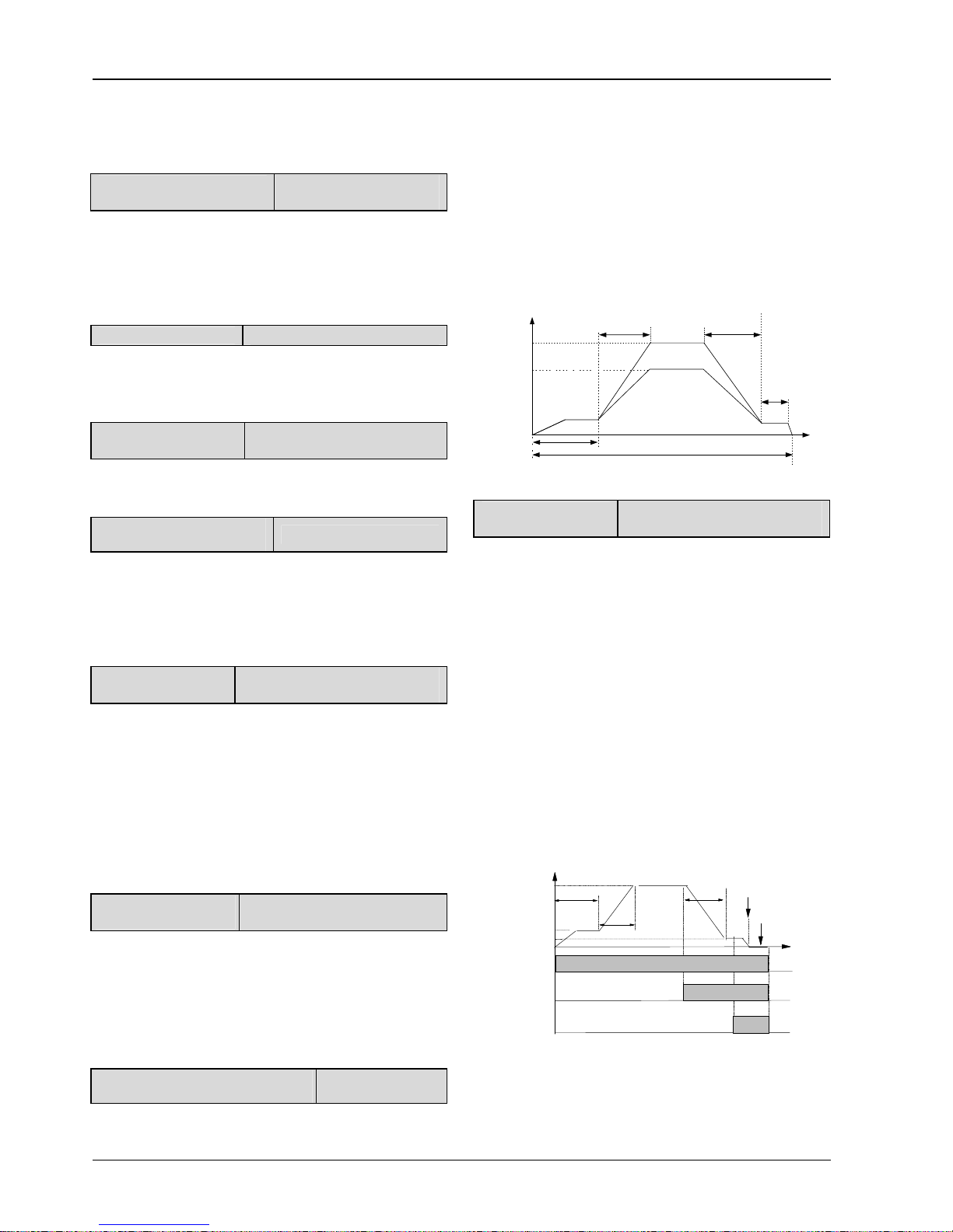
Chapter 6 Parameter Description 25
EV3200 Door Control Inverter User Manual
When the rush hour operation signal is active, this
parameter defines the frequency (speed) the inverter
operates at high speed in OD process, or the running
frequency in the general-purpose inverter mode.
F1.06 OD speed decrease
point in distance control
Setting range: 60% ~
95%(door width)【70%】
In the OD process under distance control, the pulse number
is recorded in real time. When the pulse number is bigger or
equal to the product of F1.06 and the door width, the
inverter will switch from OD speed to OD ending creep
speed.
F1.07 OD Dec time
Setting range: 0.1 ~ 3600s【2.0s
】
Defines the time taken for the inverter to decelerate from the
OD frequency (high speed) to the OD ending creep speed in
OD process.
F1.08 OD ending creep
speed
Setting range: 0 ~ 15.00Hz
【
3.00Hz】
Defines the motor’s low frequency (speed) after the OD low
speed signal is active in OD process.
F1.09 OD position limit in
distance control
Setting range: 1 ~ 9999【600
】
In OD process under distance control, the pulse number is
recorded in real time. When the result of total door-width
pulse number subtracts the pulse number already passed is
smaller or equal to the value of F1.09, OD completion
processing is implemented.
F1.10 Threshold for
OD torque changing
Setting range: 0.0% ~ 100.0% (motor
rated torque)【50.0%】
In OD process, if the OD position limiting signal is active or
the pulse count for distance control reaches the product of
F1.09 and the door width, the inverter continues to run at
low speed in the ending phase of OD. When the door
reaches the limited position, the motor is caught. When the
motor catching torque is bigger or equal to the product of
F1.10 and motor's rated torque, the door is in complete OD
status and maintaining the current torque until the door
opens again or stops.
F1.11 Maintaining torque
at OD completion
Setting range: 0.0% ~ 100.0% (motor
ratd torque)【50.0%】
When the motor is in OD operating process, the OD position
limiting function is enabled. When the torque of catching
spinning motor is bigger or equal to the setting of F1.10, and
in the mean time the torque maintaining prohibition function
is disabled, the inverter maintains at complete OD status
with the maintaining torque of the product of F1.11 and
motor's rated torque.
F1.12 OD operation curve selection in
distance control
Setting range: 0 ~ 1【0
】
0: F1.04 setting is observed in OD operation.
1: F1.04 and F1.06 are invalid, the OD process observes
the best OD speed and speed decrease point calculated
automatically based on the door width, OD optimum curve
correction factor (F1.13), Acc time and Dec time. As the
operation curve shows in Figure 6-7, when the OD creep
distance S1, OD optimum curve correction factor (F1.13)
and door width S are determined, adjust the OD Acc time
(F1.03) and OD Dec time (F1.07) to regulate the Acc slope
and Dec slope of the operation curve (the shorter the time,
the steeper the slope, and the higher the max frequency),
so as to achieve the highest OD efficiency.
Frequency
S1
S
Max. freq. 1
Max. freq. 2
Acc
Dec
F1.13
Door width
Figure 6-7 Optimum OD curve for distance control
F1.13 OD optimum
curve correction factor
Setting range: 3.0% ~ 15.0% (door
width)【10.0%】
When the inverter runs at the optimum OD curve (F1.12 =
1), the pulse number is recorded in real time in the OD
process under distance control. When the left pulse number
is smaller than or equal to the product of F1.13 and the door
width, the inverter will switch from OD speed to OD ending
creep speed. See Figure 6-7.
6.3 CD Operation Parameters F2
6.3.1 CD Operation Curve For Speed Control
Set the parameters in F2 group related to speed control,
define the speed decrease contacts and position limiting
signal accurately. CD operation curve is illustrated in Figure
6-8.
Frequency
F2.04
Time
F2.02
F2.08
F2.00
F2.11
F2.10
F2.03
F2.07
CD
CD speed
decrease signal
CD position
limiting signal
ON
OFF
ON
OFF
ON
OFF
Figure 6-8 CD operation curve for speed control
CD process of speed control:
1. When the CD command is active, the inverter starts at
start creep speed (F2.02), and then operates at constant
speed in low-speed section.
Page 30

26 Chapter 6 Parameter Description
EV3200 Door Control Inverter User Manual
2. Timing begins when CD starts. When the CD start creep
time (F2.00) is over, the inverter starts to operate at CD
reference frequency (F2.04), and accelerates according to
CD Acc time (F2.03), and then operates at high speed after
the acceleration.
3. When the CD speed decrease signal is active, the
inverter decelerates within CD Dec time (F2.07) to CD
ending creep speed (F2.08), and operates at constant
ending speed in low-speed section when deceleration is
over.
4. When CD position limiting signal is active, the inverter
continues to run at CD low speed, and the inverter judges
the output torque. If the torque is bigger or equal to the
threshold of CD torque changing (F2.10), the inverter will
keep the CD torque of F2.11, thus the whole CD process is
over.
5. When OD command is cancelled, the inverter will not
maintain the OD torque any more.
6.3.2 CD Operation Curve For Distance Control
The operation curve parameters in group F2 related to
distance control should be set correctly.
Door width auto-learning should be implemented before
distance control. The CD speed curve of distance control is
illustrated in Figure 6-9.
CD
ON
OFF
0
0
×
0
F2.11
F2.10
F2.15
F2.07
F2.03
F2.04
F2.02
F2.16
F2.08
F2.01
D2
D1
D3D4
F2.09
Frequency
CD start creep
distance
CD speed
decrease distance
CD position
limiting distance
Door width
×
F2.06
Door width
Time
Door width
Door width
Door width
Figure 6-9 CD operation curve for distance control
CD process of distance control 1:
1. When the CD command is active, the inverter starts at
start creep speed (F2.02), and then operates at constant
speed in low-speed section.
2. When reaching D1, the inverter starts to operate at CD
reference frequency (F2.04), and accelerates according to
CD Acc time (F2.03), and then operates at high speed after
the acceleration.
3. When reaching D2, the inverter decelerates within CD
Dec time (F2.07) to CD ending creep speed (F2.08), and
operates at constant ending speed in low-speed section
when after the deceleration.
4. When reaching D3, the inverter will run at the CD speed
after door locking point (F2.16), speeding up the CD
process.
5. When reaching D4, the inverter continues to run at CD
speed after door locking point. If the output torque is bigger
or equal to the threshold for CD torque changing (F2.10),
the inverter will maintain the torque of F2.11, thus the whole
CD process is over.
5. When CD command is disabled, the inverter exits the CD
torque maintaining status.
F2.00 CD start creep time for
speed control
Setting range: 10 ~ 9999ms
【
500ms】
Defines the duration the inverter operates at start creep
speed in CD process under speed control.
F2.01 CD start creep
distance
Setting range: 0 ~ 30.0% (door width)
【
15.0%】
In CD process under distance control, the pulse number is
recorded in real time. When the pulse number is bigger or
equal to the product of F2.01 and the door width, the
inverter switches from CD start creep speed (F2.02) to CD
high speed (F2.04).
F2.02 CD start creep speed
Setting range: 1.00 ~ 25.00Hz
【
6.00Hz】
Defines the low operating frequency (speed) in CD process.
F2.03 CD Acc time
Setting range: 0.1s ~ 3600s【2.0s
】
Defines the time taken for the inverter to accelerate from the
CD start creep speed to the CD frequency.
F2.04 CD reference
frequency
Setting range: 0.00 ~ max
frequency【15.00Hz】
Defines the high operating frequency (speed) in CD
process.
F2.05 Rush hour
operation CD speed
Setting range: 0.00 ~ max
frequency【20.00Hz】
When the rush hour operation signal is active, this
parameter defines the frequency (speed) the inverter
operates at high speed in CD process, or the running
frequency in the general-purpose inverter mode.
F2.06 CD speed decrease
point in distance control
Setting range: 60% ~ 95%
(door width)【70%】
In the CD process under distance control, the pulse number
is recorded in real time. When the pulse number is bigger or
equal to the product of F2.06 and the door width, the
inverter will switch from CD high speed to CD ending creep
speed.
F2.07 CD Dec time
Setting range: 0.1 ~ 3600s【2.0】
Page 31

Chapter 6 Parameter Description 27
EV3200 Door Control Inverter User Manual
Defines the time taken for the inverter to decelerate from the
CD frequency (high speed) to the CD ending creep speed in
CD process.
F2.08 CD ending creep
speed
Setting range: 0 ~ 15.00Hz【2.00
】
Defines the motor’s low frequency (speed) after the CD low
speed signal is active in CD process.
F2.09 CD position limit in
distance control
Setting range: 1 ~ 9999【600
】
In CD process under distance control, the pulse number is
recorded in real time. When the pulse number is smaller
than or equal to the value F2.09, CD completion processing
is implemented.
F2.10 Threshold for CD torque
changing
Setting range: 0.0% ~
100.0%【50.0%】
In CD process, if the CD position limiting signal is active or
the pulse count for distance control reaches the product of
F2.09 and the door width, the inverter continues to run at
low speed in the ending phase of CD. When the door
reaches the limited position, the motor is caught. When the
motor catching torque is bigger or equal to the product of
F2.10 and motor's rated torque, the door is in complete CD
status and maintaining the current torque until the door
opens again or stops.
F2.11 Maintaining
torque at CD completion
Setting range: 0.0% ~ 100.0%
【
50.0%】
When the motor is in CD operating process, the CD position
limiting function is enabled. When the torque of catching
spinning motor is bigger or equal to the setting of F2.10, and
in the mean time the torque maintaining prohibition function
is disabled, the inverter maintains at complete CD status
with the maintaining torque of the product of F2.11 and
motor's rated torque.
F2.12 CD high speed
for EFS
Setting range: 5.00 ~ 25.00Hz
【
10.00】
Defines the high speed at which the inverter operates when
emergency fireman service (EFS) signal is active.
F2.13 CD operation curve
selection in distance control
Setting range: 0 ~ 1【0】
0: F2.04 setting is observed in CD operation.
1: F2.04 and F2.06 are invalid, the CD process observes
the best CD speed and speed decrease point calculated
automatically based on the door width, CD optimum curve
correction factor (F2.14), Acc time and Dec time. As the
operation curve shows in Figure 6-10, when the CD
distance S1, CD optimum curve correction factor (F2.14)
and door width S are determined, adjust the CD Acc time
(F2.03) and CD Dec time (F2.07) to regulate the Acc slope
and Dec slope of the operation curve (the shorter the time,
the steeper the slope, and the higher the max frequency),
so as to achieve the highest CD efficiency.
Frequency
S1
S
Max. freq. 1
Max. freq. 2
Acc
Dec
F2.14
Door width
Figure 6-10 Optimum CD curve for distance control
F2.14 CD optimum curve
correction factor
Setting range: 3.0% ~
15.0%【10.0%】
When the inverter runs at the optimum CD curve (F2.13 = 1),
the pulse number is recorded in real time in the CD process
under distance control. When the left pulse number is
smaller than or equal to the product of F2.14 and the door
width, the inverter will switch from CD speed to CD ending
creep speed. See Figure 6-10.
F2.15 Distance control CD door
locking point
Setting range: 3.0% ~
15.0%【10.0%】
In CD process under distance control, the pulse number is
recorded in real time. When the pulse number is smaller
than or equal to the pulse number set by F2.15, the CD door
locking processing is implemented.
F2.16 CD speed after door locking
point
Setting range: 0 ~
20.00Hz 【5.00】
Defines the operating frequency after the door locking point
in the CD process.
6.4 Enhanced Function Parameters
F3
F3.00 INI operation
speed
Setting range: 0.00 ~ 20.00Hz
【
5.00Hz】
1. Defines the first time OD and CD speed after inverter
power-on, under distance control, without 3-section speed
curve.
2. Defines the OD and CD speed when slow OD and CD
signals are active, without 3-section speed curve.
F3.01 OD time limit
Setting range: 0 ~ 3600s【300s】
Defines the maximum time of OD operation. You should set
it properly according to the actual conditions. The setting
must be bigger or equal to the sum of all the settings of OD
(parameter group of OD curve), otherwise error may occur
(E028). Setting F3.01 correctly can protect the system
against abnormal operation of elevator door. Normal
operation time will not exceed F3.01, but when the OD
position limit is invalid and causes the OD process unable to
Page 32

28 Chapter 6 Parameter Description
EV3200 Door Control Inverter User Manual
be completed, the operation time may exceed F3.01, and
OD error (E030) will be activated. E029 will be activated if
OD overtime occurred during the door width auto-learning.
When you set F3.01 to 0 or 3600, that is, set the OD time
limit to infinity, F3.01 is invalid.
F3.02 CD time limit
Setting range: 0 ~ 3600s【300s】
Defines the maximum time of CD operation. You should set
it properly according to the actual conditions. The setting
must be bigger or equal to the sum of all the settings of CD
(parameter group of CD curve), otherwise error may occur
(E028). Setting F3.02 correctly can protect the system
against abnormal operation of elevator door. Normal
operation time will not exceed F3.02, but when the CD
position limit is invalid and causes the CD process unable to
be completed, the operation time may exceed F3.02, and
CD error (E031) will be activated. E029 will be activated if
OD overtime occurred during the door width auto-learning.
When you set F3.02 to 0 or 3600, that is, set the CD time
limit to infinity, F3.02 is invalid.
F3.03 Slow speed
operation time limit
Setting range: 0 ~ 3600s【400s
】
Defines the maximum time of slow OD and CD operation
when slow operation enable signal is active. You should set
it properly according to the actual conditions. The setting
must be bigger or equal to the sum of all the settings of OD
or CD (parameter group of OD curve and CD curve),
otherwise error may occur (E028). Setting F3.03 correctly
can protect the system against abnormal slow operation of
elevator door. Normal operation time will not exceed F3.03,
but when the OD or CD position limit is invalid and causes
the OD or CD process unable to be completed, the
operation time may exceed F3.03, and OD or CD error
(E030, E031) will be activated. When you set F3.03 to 0 or
3600, that is, set the OD or CD time limit to infinity, F3.03 is
invalid.
F3.04 Delay time for external OD
command
Setting range: 0 ~ 9999s
【0s】
Defines the time interval from the OD command becoming
invalid to the end of maintaining time of complete OD state.
If the maintaining time is equal to or greater than F3.04, the
inverter will stop. If the door is not opened to the position
completely and OD command is cancelled at that time, the
inverter will stop immediately and the delay function is
invalid. If F3.04 is set to 9999, the OD delay, once triggered,
will be maintained endlessly.
F3.05 Delay time for external CD
command
Setting range: 0 ~ 9999s
【0s】
Defines the time interval from the CD command becoming
invalid to the end of maintaining time of complete CD state.
If the maintaining time is equal to or greater than F3.05, the
inverter will stop. If the door is not closed to the position
completely and CD command is cancelled at that time, the
inverter will stop immediately and the delay function is
invalid. If F3.05 is set to 9999, the CD delay, once triggered,
will be maintained endlessly.
F3.06 Position of safety edge lift
signal output
Setting range: 0% ~
40.0%(door width)【10%
】
When the door position ≤ F3.06 × door width, safety edge lift
is needed. In this case, if safety edge lift signal output
function is configured, safety edge lift signal will be activated.
when the door position ≥ F3.07 × door width, safety edge lift
signal will not be activated.
CD
OD
Door width
F3.06×
door width
Safety edge
lift signal output
Figure 6-11 Safety edge lift signal output position
F3.07 Function selection of OD
upon CD obstruction
Setting range: 0 ~ 1【1
】
Defines the handling method in the case CD process is
obstructed.
0: stop. The CD process can continue only after 10s, unless
OD operation is conducted within 10s.
1: re-open the elevator door
F3.08 CD obstruction
sensitivity
Setting range: 0 ~ 150%【100%
】
During CD process, the motor's output torque is detected in
real time. When the output torque is bigger than or equal to
the product of F3.08 and motor rated torque, it is regarded
that the CD process is obstructed, and the situation will be
addressed according to the setting of F3.07
When set to 0, CD obstruction sensing is disabled.
F3.09 Dec time upon
abnormality
Setting range: 10 ~ 2500ms【300ms
】
Defines the time taken for the inverter to decelerate from
current CD speed to zero in the case CD process is
obstructed.
Under the precondition of no over-current in Dec process,
F3.09 should be set as small as possible.
F3.10 OD obstruction
sensitivity
Setting range: 0 ~ 150%【0%】
During CD process, the motor's output torque is detected in
real time. When the output torque is bigger than or equal to
the product of F3.10 and motor rated torque, it is regarded
that the OD process is obstructed, the inverter will stop
immediately. The door can be opened 10s later, or if CD
operation is implemented within 10s.
When set to 0, OD obstruction sensing is disabled.
Page 33

Chapter 6 Parameter Description 29
EV3200 Door Control Inverter User Manual
OD obstruction
signal
OD signal
Running frequenc y
(positive for OD,
negative for CD)
10s
<10s
Time
CD signal
Time
Time
Time
Figure 6-12 Time sequence diagram for OD obstruction
F3.11 Maintaining time for
complete OD in demo mode
Setting range: 1 ~ 3600s
【
2.0】
Defines the interval from complete OD to CD in demo mode.
It can be set according to the actual requirement of demo.
F3.12 Maintaining time for
complete CD in demo mode
Setting range: 1 ~ 3600s
【
2.0】
Defines the interval from complete CD to OD in demo mode.
It can be set according to the actual requirement of demo.
F3.13 Preset CD/OD times in
demo mode
Setting range: 0 ~ 9999
【0】
Defines the operation times in demo mode. When the actual
operation times is bigger than the setting of F3.13, the demo
is ended automatically.
If F3.13=0, this function is disabled and demo will not be
ended automatically.
F3.14 CD/OD times record in
demo mode
Range: 0 ~ 9999【0】
F3.14 is the recorded CD and OD times in demo mode. The
value is saved upon power off. When the inverter is
powered on the next time, the operation times in demo
mode will be counted and added to the previous value of
F3.14. One is added every time the door is opened or
closed.
Demo mode is a cyclic operation of OD and CD. Pressing
the
key starts the demo. The door is opened according
to the operation curve. The inverter starts timing after the
door is opened completely. When the time reaches the
setting of F3.11, the inverter starts reverse running, and the
door is closed. The inverter starts timing after the door is
closed completely. When the time reaches the setting of
F3.12, the door is opened again. The door is thus opened
and closed repeatedly. Pressing the
key ends the demo.
Demo can be under both speed control and distance control.
It can be used for demonstration and burning test.
F3.15 Auto restet times
upon fault
Setting range: 0 ~ 100【0】
When fault occurs while the inverter is running, the inverter
stops its output. Two seconds later, it will reset automatically
and continue to run.
Setting this parameter disables the automatic reset function,
and the inverter can only be reset by manually.
Note
The inverter will not reset automatically when E024, E025, E028,
E029, E030, E031 faults occur.
F3.16 Torque enhance coefficient
Setting range: 100% ~
350%【115%】
This parameter is used to enhance the switching torque in
first time operation or self-learning process, so as to prevent
error action.
F3.17 Fan control
Setting range: 0 ~ 2【0
】
0: fan does not start during inverter operation
1: fan starts when heatsink temperature is higher than 65°C during
inverter operation
2: fan starts during inverter operation
F3.18 Percentage or pulse
number selection
Setting range: 0 ~ 1【0
】
0: F1.01, F1.06, F1.13, F2.01, F2.06 and F2.14 are percentages.
1: F1.01, F1.06, F1.13, F2.01, F2.06 and F2.14 are numbers.
After confirming the setting of F3.18 as 0, function codes F1.01,
F1.06, F1.13, F2.01, F2.06 and F2.14 are based on the percentage
of door width. On the other hand, after confirming the setting of
F3.18 as 1, such function codes are based on the actual pulse
number.
Note
1. After changing F3.18 from 0 to 1, and after getting the door
width or the door width total pulse number, function codes F1.01,
F1.06, F1.13, F2.01, F2.06 and F2.14 must be reset based on the
door width pulse number.
2. When F3.18 is set to 1, the setting ranges of F1.01, F1.06,
F1.13, F2.01, F2.06 and F2.14 are 0 ~ 32767. If the set pulse
number is bigger than 9999, only the higher 4 digits will be
displayed, while the decimal point after the forth digit will be
lighted to indicate that the fifth digit is not displayed.
6.5 Door Width Self-learning
Parameters F4
F4.00 PG type
Setting range: 0, 1【0】
Set F4.00 correctly according to the selected PG type.
If 24V incremental PG (open-collector or push-pull type) is
selected, set F4.00 to 0. If UVW incremental PG is selected,
set F4.00 to 1.
Note
1. For inverters EV3200-2S0002A and EV3200-2S0004A, the
default setting of this parameter is 0.
2. For inverters EV3200-2S0002S and EV3200-2S0004S, the
default setting of this parameter is 1.
3. Function code F4.00 changes automatically with the change of
F6.00. The value of F4.00 is always kept the same as F6.00.
Page 34

30 Chapter 6 Parameter Description
EV3200 Door Control Inverter User Manual
F4.01 Pulse number per
revolution
Setting range: 0 ~ 4000
【
100】
F4.02 PG direction
Setting range: 0, 1【0】
EV3200 inverter adopts vector control mode. Relevant
parameters of PG must be set if close loop vector control
mode is adopted.
In distance control mode, relevant parameters of PG should
also be set correctly so as to ensure the control effects.
EV3200 can only use two-phase PG.
Note
1. EV3200 asynchronous inverter can only use 24V open collector
or 24V push-pull PG.
2. EV3200 synchronous inverter can use 5V UVW incremental
PG.
3. For EV3200-2S0002A and EV3200-2S0004A, the default
setting of F4.01 is 100.
4 For EV3200-2S0002S and EV3200-2S0004S, the default setting
of F4.01 is 2500.
5. Function code F4.01 changes automatically with the change of
F6.00. When F6.00 is set to 0, F4.01 will change automatically to
200; when F6.00 is set to 1, F4.01 will change automatically to
2500.
F4.03 Magnetic pole initial
angle
Setting range: 0.0 ~ 359.9【0】
When driving a synchronous motor, the magnetic pole nitial
angle of the motor will be obtained automatically after
tuning.
F4.04 Speed during door
width auto-learning
Setting range: 2.00 ~ 20.00Hz
【
5.00】
Defines the operating frequency in door width auto-learning
process.
In order to reduce the door width error, this parameter must
not be too big so as to avoid the shock when the door is in
complete OD or CD status.
F4.05 Selection of door-width
auto-learning
Setting range: 0, 1【0】
0: disabled
1: enabled
Set F4.05 to 1, press
(or when terminal auto-learning
command is valid)
, and the inverter will begin door-width
auto-learning automatically.
After the auto-learning, the setting of F4.05 will be restored
to 0 automatically.
Process of door-width auto-learning: After auto-learning is
started, the door will be closed, opened and then closed.
After the auto-learning is finished, the door width information
will be saved automatically.
Note
1. Relevant parameters of PG must be input correctly before the
auto-learning.
2. During auto-learning, there must not be any obstacles on the
slide rail of the door.
3. If you use the terminal to input the auto-learning command, you
should set F4.05 to 1 in advance as well.
4. If you use terminal to input the auto-learning command, you are
required to set F4.05 to 1 in advance.
5. Door width auto-learning function is valid in distance control
mode (F0.01=0).
6. The door width can be obtained manually when the inverter in
standby state. First, set F4.07 to 9999, close the elevator door
manually, and the inverter will display the CD complete pulse
value (P1); then pull the door open completely, and the inverter
will display the OD complete pulse value (P2). The high digits
and low digits of P1 and P2 can be displayed by setting the F9.01.
Refer to description of F9.01.
Calculate the door width (door width=|P2 - P1|), and input the
door width through F4.06 and F4.07.
F4.06 Low digits of pulse count
Setting range: 0 ~ 9999【0
】
The parameter saves the four low digits of pulse count
obtained by door width auto-learning (max: four digits).
F4.07 High digits of pulse count
Setting range: 0 ~
9999(× 10000)【0】
The parameter saves the high digits of pulse count obtained
by door width auto-learning.
Door width= F4.07 × 10000+F4.06
The pulse number of door width obtained by auto-learning
can be changed via operation keypad.
F4.08 Actual door width
Setting range: 0 ~ 9999mm
【
0mm】
You may input the actual door width through F4.08, that is
complete CD is 0 and complete OD is the actual width set
by F4.08. When F4.08 is not 0, the door position is the
actual position in the unit of mm; when F4.08 is 0, the door
position is expressed by pulse number.
F4.09 PG cable broken detection
time for asynchronous motor
Setting range: 0.0 ~
10.0s【0s】
When the PG input signal is detected abnormal, after the
time set by F4.09, the inverter will report PG cable broken
fault. If F4.09 is set to 0, PG cable broken detection function
is disabled.
F4.10 Ratio of gear
Setting range: 1.0 ~ 100.0【1.0】
The ratio of shaft radius of traction wheel to motor shaft
radius, as shown in Figure 6-13.
Ratio of gear = shaft radius of traction wheel N1/motor shaft
radius N2.
Page 35

Chapter 6 Parameter Description 31
EV3200 Door Control Inverter User Manual
Pulley
Traction wheel
N1
Motor shaft
N2
Figure 6-13 Illustration of ratio of gear
F4.11 Asynchronous
single/dual motor selection
Setting range: 0 ~ 1【0】
0: single motor control (asynchronous or synchronous).
1: dual motors control (asynchronous).
When F4.11 is set 0, the inverter works in the single motor
control mode, which is the only mode for synchronous
motors. When F4.11 is set 1, the inverter works in dual
asynchronous motors control mode, the inverter then can
two asynchronous motors whose parameters are set the
same. However, the motor tuning operation requires the
single motor control mode (F4.11 = 0), or the system will
report E028.
6.6 Multi-function Input Terminal
Parameters F5
Functions and parameters of control terminals X1 ~ X5 are
defined by the following parameters.
F5.00 Function selection for
control terminal X1
Setting range: 0 ~ 20【0
】
F5.01 Function selection for
control terminal X2
Setting range: 0 ~ 20【0
】
F5.02 Function selection for
control terminal X3
Setting range: 0 ~ 20【0
】
F5.03 Function selection for
control terminal X4
Setting range: 0 ~ 20【0
】
F5.04 Function selection for
control terminal X5
Setting range: 0 ~ 22【0
】
Control terminals X1 ~ X5 are programmable input terminals,
and their functions can be defined by F5.00 ~ F5.04. The
functions are listed in Table 6-1.
Table 6-1 Function selection for multi-function inputs
Settings Functions Settings Functions
0 No functions 12
Normally open input
contacts for CD
speed decrease
1
External reset (RESET)
signal input
13
Normally closd input
contacts for CD
speed decrease
2
Normally open input
contacts for light curtain
signal
14
Terminal for inputting
OD prohibition signal
3
Normally closed input
contacts for light curtain
signal
15
Terminal for
disabling torque
maintaining
Settings Functions Settings Functions
4
Normally open input
contacts for safety edge
16
Low speed OD/CD
enable signal input
5
Normally closed input
contacts for safety edge
17
Normally open input
for lock signal
6
Normally open input for
OD position limiting
18
Normally closed
input for lock signal
7
Normally closed input for
OD position limiting
19 EFS function input
8
Normally open input for
CD position limiting
20
Rush hour operation
enable signal input
9
Normally closed input for
CD position limiting
21
Operation enable
signal input (valid for
X5 only)
10
Normally open input
contacts for OD speed
decrease
22
Door width
auto-learning
command input
(valid for X5 only)
11
Normally closed input
contacts for OD speed
decrease
Note
When setting parameters from F5.00 to F5.04, only 0 (no function)
can be set repetitively, other settings (1 ~ 22) can not.
0: No function
1: External reset (RESET) signal input
When a fault occurs, the inverter can be reset via this
terminal. This function is enabled at the falling edge of the
pulse, and its function is the same with that of the
key
on the keypad.
2, 3: Normally open/closed input contacts for light curtain
signal
In CD process, if this terminal is activated, CD obstruction
protection will be executed. During the re-opening process,
the inverter will not response to CD command.
If the door has reached the CD position limit, this protection
signal is ineffective.
4, 5: Normally open/closed input contacts for safety edge
In CD process, if this terminal is activated, CD obstruction
protection will be executed. During the re-opening process,
the inverter will not response to CD command.
If the door has reached the CD position limit, this protection
signal is ineffective.
6, 7: Normally open/closed input for OD position limiting
In OD process under speed control, the inverter will take
actions of OD position limiting after this signal is enabled.
8, 9: Normally open/closed input for CD position limiting
In CD process under speed control, the inverter will take
actions of CD position limiting after this signal is enabled.
10, 11: Normally open/closed input for OD speed decrease
In OD process under speed control, the inverter starts low
speed operation in ending phase after the normally
open/closed input for OD speed decrease is enabled.
Page 36

32 Chapter 6 Parameter Description
EV3200 Door Control Inverter User Manual
12, 13: Normally open/closed input for CD speed decrease
In CD process under speed control, the inverter starts low
speed operation in ending phase after the normally
open/closed input for CD speed decrease is enabled.
14: Terminal for inputting OD prohibition signal
OD command will not be executed if this signal is enabled.
15: Terminal for inputting torque maintaining prohibition
signal
In CD/OD torque maintaining process, the inverter will
maintain the 0 torque if this signal is enabled.
16: Low speed OD/CD enabling signal input
If this signal is enabled, the motor operates at low speed
according to the speed set by F3.00.
17/18: Normally open/closed input for lock signal
19: EFS signal input
When this signal is activated, OD is prohibited, and the door
closes at the high speed set by F2.12.
20: Rush hour operation enable signal input
When the signal is activated, the OD speed and CD speed
are the speeds set by F1.05 and F2.05 respectively.
21: Operation enable signal input
when X5 is not set to 21, the door is controlled by the
external door control signals.
When X5 is set to 21:
If X5 is valid, external door control is enabled.
If X5 signal is invalid, the inverter will stop immediately
when in operation state, and does not respond when
in stopping state.
22: Door width auto-learning command input
Under terminal control mode (F0.02=2), when X5 is set to
22:
If F4.05=1 and X5 terminal input command is valid,
door width auto-learning will start.
If F4.05=0 and X5 terminal input command is valid,
door width auto-learning will not start.
F5.05 Function of programmable relay
output PA1/PC1
Setting range: 0 ~ 11
【2】
F5.06 Function of programmable relay
output PA2/PC2
Setting range: 0 ~ 11
【3】
F5.07 Function of programmable relay
output PA3/PB3/PC3
Setting range: 0 ~ 11
【6】
Functions of programmable relay are shown in Table 6-2.
Table 6-2 Relay output functions
Settings Functions Settings Functions
0
Output signal 0 for
complete OD
6 Fault relay output 1
1
Output signal 0 for
complete CD
7 Fault relay output 2
Settings Functions Settings Functions
2
Output signal 1 for
complete OD
8
Safety edge lift signal
output
3
Output signal 1 for
complete CD
9
Lock signal synchronous
output
4
Output signal 2 for
complete OD
10
Re-opening signal
output
5
Output signal 2 for
complete CD
11
Obstruction signal
output
0: Output signal 0 for complete OD
In OD process, when the inverter receives OD position
limiting signal or when the pulse count number reaches the
OD position limit, the relay will activate to output OD
complete signal.
Complete OD signal is disabled in demo mode,
general-purpose inverter operation mode and CD process.
1: Output signal 0 for complete CD
In CD process, when the inverter receives CD position
limiting signal or when the pulse count number reaches the
CD position limit, the relay will activate to output CD
complete signal.
The complete CD signal is disabled in demo mode,
general-purpose inverter operation mode and OD process.
2: Output signal 1 for complete OD
In OD process, when the inverter receives OD position
limiting signal or when the pulse count number reaches the
OD position limit, and at the same time the inverter torque
reaches the setting of F1.10, the relay will activate to output
OD complete signal.
The complete OD signal is disabled in demo mode,
general-purpose inverter operation mode and CD process.
3: Output signal 1 for complete CD
In CD process, when the inverter receives CD position
limiting signal or when the pulse count number reaches the
CD position limit, and at the same time the inverter torque
reaches the setting of F2.10, the relay will activate to output
CD complete signal.
The complete CD signal is disabled in demo mode,
general-purpose inverter operation mode and OD process.
4: Output signal 2 for complete OD
In OD process, when the inverter receives OD position
limiting signal or when the pulse count ed reaches the OD
position limit, locking signal is invalid and at the same time
the inverter torque reaches the setting of F1.10, the relay
will activate to output OD complete signal.
The complete OD signal is disabled in demo mode,
general-purpose inverter operation mode and CD process.
5: Output signal 2 for complete CD
In CD process, when the inverter receives CD position
limiting signal or when the pulse count ed reaches the CD
position limit, locking signal is disabled and at the same time
Page 37

Chapter 6 Parameter Description 33
EV3200 Door Control Inverter User Manual
the catching torque reaches the setting of F2.10, the relay
will activate to output CD complete signal.
The complete CD signal is disabled in demo mode,
general-purpose inverter operation mode and OD process.
6: Fault relay output 1
When the inverter has fault, the relay will output fault signal.
But when parameter setting error (E028) occurs, the inverter
only displays the alarm information and will not output fault
relay output signal 1.
7: Fault relay output 2
When the inverter has fault or the inverter's DC bus voltage
is low (LED displays "P.oFF"), the relay will output fault
signal. But when parameter setting error (E028) occurs, the
inverter only displays the alarm information and will not
output fault relay output signal 2.
8: Safety edge lift signal output
When width left open in CD is less than or equal to F3.06
setting, the relay outputs safety edge lift signal. When it is
bigger than F3.06 setting, there is no output of safety edge
lift signal.
9: Lock signal output
Synchronously input/output lock signal
10: Door re-opening signal output
In door re-opening process, the relay outputs the door
re-opening signal.
11: Obstruction signal output
When the door is obstructed in OD or CD process, the relay
outputs this signal.
6.7 Motor Parameters F6
F6.00 Motor type selection
Setting range: 0 ~ 1【0
】
0: asynchronous motor
1: synchronous motor
Note
1. For EV3200-2S0002A and EV3200-2S0004A, the default
setting of this parameter is 0.
2. For EV3200-2S0002S and EV3200-2S0004S, the default
setting of this parameter is 1.
F6.01 Motor rated power
Setting range: 0 ~ 500W【370】
F6.02 Motor rated voltage
Setting range: 0 ~ 250V【220】
F6.03 Motor rated current
Setting range: 0.10 ~ 9.90A【1.94
】
F6.04 Motor max
allowable operation current
Setting range: 100.0% ~ 200.0%
【
150%】
F6.05 Motor rated
frequency
Setting range: 1.00 ~ 128.00Hz
【
50.00】
F6.06 Motor rated
spinning speed
Setting range: 1 ~ 9999rpm【1400
】
Set the motor parameters according to the nameplate.
Note
1. Relevant parameters of motor (F6.01 ~ F6.06) must be input
correctly before auto-tuning.
2. The motor power should match that of the inverter, that is, the
setting of F069 can be only one grade higher or two grades lower
than standard motor capacity, to ensure the performance.
F6.07 Motor tuning
Setting range: 0, 1【0
】
0: disable 1: enable
Enter the motor parameters according to the nameplate
(F6.01 ~ F6.06) before tuning. First set F6.07 to 1, press
on the operation keypad, the inverter will execute
auto-tuning function.
After tuning completed, setting of F6.07 will be restored to 0
automatically.
Note
1. Do not start tuning with load on motor;
2. Make sure the motor is in stopping status before tuning,
otherwise, the tuning can not be processed normally;
3. Tuning can be performed in keypad control mode only
(F0.02=0, factory default value);
F6.08 Stator resistance
Setting range: 0.00 ~ 99.99Ω【7.73
】
F6.09 Stator inductance
Setting range: 0 ~ 9999mH【357】
F6.10 Rotor resistance
Setting range: 0.00 ~ 99.99Ω【5.23
】
F6.11 Rotor inductance
Setting range: 0 ~ 9999mH【357】
F6.12 Mutual inductance
Setting range: 0 ~ 9999mH【325】
F6.13 Exciting current
with no load
Setting range: 0.00 ~ 99.99A【1.08
】
After auto-tuning, settings of F6.08 ~ F6.13 will be updated.
Each time after changing the parameters on the motor's
nameplate, the settings of F6.08 ~ F6.13 will be restored to
defaults automatically.
Motor's parameters are illustrated in Figure 6-14.
R
m
L
m
I
0
I
1
U
1
R
1
L1-L
m
R
2
L2-L
m
1-S
S
R
2
I
2
Figure 6-14 Steady-state equivalent circuit of asynchronous
motor
In Figure 6-14, R1, L1, R2, L2, Lm, I0 represent stator
resistance, stator inductance, rotor resistance, rotor
inductance, mutual inductance and exciting current
respectively.
6.8 Vector Control Parameters F7
F7.00 Speed regulator's
proportional gain 1
Setting range: 0.000 ~ 6.000
【
0.600】
Page 38

34 Chapter 6 Parameter Description
EV3200 Door Control Inverter User Manual
F7.01 Speed regulator's
integral time 1
Setting range: 0, 0.032 ~ 32.00s
【
1.000】
F7.02 Speed regulator's
proportional gain 2
Setting range: 0.000 ~ 6.000
【
0.600】
F7.03 Speed regulator's
integral time 2
Setting range: 0, 0.032 ~ 32.00s
【
1.000】
F7.04 Speed regulator's
changing frequency
Setting range: 0.00 ~ 50.00Hz
【
5.00】
Speed regulator's proportional gain P and integral time I can
be set by F7.00 ~ F7.04 to change the speed response of
vector control.
1. Structure of speed regulator (ASR) is shown in Figure
6-15, where K
p is proportional gain P, and KI is integral time
I.
Frequency
instruction
Actual speed
Reference
torque current
+
Speed
error
Torque limit
(F7.06, F7.07)
Kp(1+ )
1
KI S
-
Figure 6-15 Simplified speed regulator diagram
If the integral time is set at 0 (F7.01=0, F7.03=0), which
means integral function is disabled, and the speed loop is
simply a proportion regulator.
2. Adjustment of proportional gain P and integral time I for
speed regulator.
Instructed
speed
Bigger proportional gain
Shorter integral time
Small proportional gain
Instructed
speed
Longer integral time
Figure 6-16 Speed regulator's step response vs. P and I
Increasing P will fasten system transient response, but
system oscillation may occur given too big P.
Decreasing I will fasten transient response, but system
oscillation and overshoot may occur given too small.
Normally, you may tune P first, increase its value as long as
no system oscillation occurs; then adjust I, ensuring fast
response without overshoot. Figure 6-17 shows better
speed step response if P, I are set properly.
Instructed speed
Figure 6-17 Step response with better dynamic performance
3. Speed regulator's P, I Settings in High/Low Speed
Applications
If the system is required to respond quickly both in low and
high frequency operation with load and, then the user may
set speed regulator's switching frequency in F7.04. Normally,
when the system runs at low frequency, the transient
response performance can be improved by increasing P
and decreasing I.
Adjust speed regulator's parameters following the
procedures below:
Set appropriate switching frequency F7.04.
First tune P (F7.00) and I (F7.01) for high-speed application,
ensuring no oscillation and short response time.
Next, tune P (F7.02) and I (F7.03) for low-speed application,
ensure no oscillation and good response performance at
low frequency.
F7.05 Slip compensation
gain
Setting range: 0, 50.0% ~
250.0%【100.0%】
F7.05 is used in calculating slip frequency. The setting
100% means rated slip frequency corresponds to rated
torque current. The user may decrease/increase the
settings of F7.05 to adjust the speed control's difference
accurately.
F7.06 Motoring
torque limit
Setting range: 0.0% ~ 200.0%
【
100.0%】
F7.07 Braking
torque limit
Setting range: 0.0% ~ 200.0%
【
100.0%】
Torque limiting is used to limit the speed regulator's output
torque current.
Torque limit is the percentage of the inverter's rated current;
if the torque limit is 100%, then the torque current limit is the
inverter's rated current. F7.06 and F7.075 limit the output
torque in motorizing state and braking state respectively, as
shown in Figure 6-18.
Motor running speed
FWD runningREV runing
Braking
status
Braking
status
Output torque
F7.07
F7.07
F7.06
F7.06
Motorizing
status
Positive torque
Negative torque
Motorizing
status
Figure 6-18 Torque limiting function
F7.08 Current loop’s
proportional gain KP
Setting range: 0 ~ 9999【500
】
F7.09 Current loop’s
integral time KI
Setting range: 0 ~ 9999【300
】
F7.08 and F7.09 are PI regulator parameters of current loop.
Increasing current loop KP or KI can fasten system transient
response to output torque; reducing KP or KI can increase
system stability.
Too big current loop KP or KI increases the possibility of
system oscillation; too small KP or KI may affect the system
torque output capability.
Page 39

Chapter 6 Parameter Description 35
EV3200 Door Control Inverter User Manual
Note
Normally, there is no need to change the PI parameters of current
loop. Do not change them unless absolutely necessary.
F7.10 Filtering coefficient
Setbting range: 0 ~ 63【27】
This parameter is the filtering coefficient for high speed and
low speed feedback, as shown in Figure 6-19.
012345
Low speed
filtering times
Bit
High speed
filtering times
Figure 6-19 Filtering coefficient
Each filtering parameter accounts for 3 bits. The decimal
number converted from the 3-bit number is the filtering
times of the filtering parameter.
For example, high speed filtering needs 3 times, the
corresponding binary number is 011B, therefore the
corresponding Bit 5, Bit 4, and Bit 3 are respectively 0, 1
and 1; low speed filtering needs 1 time, the corresponding
Bit 2, Bit 1 and Bit 0 are respectively 0, 0 and 1; so the 6-bit
binary number is 011001B, which, if converted to a decimal
number, is 25, thus 25 is the setting of F2.13.
Note
Normally, the filtering coefficient does not need adjustment, but in
applications subject to bit interference, the filtering times can be
increased.
6.9 Communication Parameters F8
(Reserved)
EV3200 inverter provides reserved standard RS485 and
CAN communication ports, which use open Modbus serial
communication protocol.
If you wish to control EV3200 inverter through
communication, you may connect it to a computer or an
PLC, or you may control it through a communication
adapter.
F8.00 Modbus baud rate selection
Setting range: 0 ~ 7【4
】
Defines the serial communication speed rate.
0: 1200bps
1: 2400bps
2: 4800bps
3: 9600bps
4: 19200bps
5: 38400bps
6: 115200bps
7: 125000bps
F8.01 Modbus data format
Setting range: 0 ~ 5【0】
Defines the data format adopted in serial communication
protocol.
0: RTU, 1 start bit, 8 data bits, 2 stop bits, no parity
1: RTU, 1 start bit, 8 data bits, 1 stop bit, even parity
2: RTU, 1 start bit, 8 data bits, 1 stop bit, odd parity
3: ASCII, 1 start bit, 7 data bits, 2 stop bits, no parity
4: ASCII, 1 start bit, 7 data bits, 1 stop bit, even parity
5: ASCII, 1 start bit, 7 data bits, 1 stop bit, odd parity
F8.02 Local Number
Setting range: 0 ~ 127【5】
Defines the address of the local inverter in the case a host
controls multiple inverters. The address of each inverter
shall not repeat.
0 is defined as the broadcast address.
F8.03 Modbus communication
failure detection time
Setting range: 0, 0.1 ~ 100.0s
【0】
If communication control mode is not selected (F0.02=0 ~ 2
or F0.02=4 ~ 5), this function is disabled.
When F8.03=0, this function is disabled.
When F8.03 is not set to 0, if the communication interrupt
lasts longer than the setting of F8.03, fault code E017
(communication error) will be displayed, and the inverter will
stop.
F8.04 Modbus communication
delay
Setting range: 0.01 ~ 1.000s
【
0.01】
You may define the response delay of the inverter in
communication according to the speed of the Modbus main
station.
In RTU mode, the actual communication delay shall not be
less than 3.5 character spaces. In ASCII mode, the actual
communication delay shall not be less than 1ms.
F8.05 CAN communication
station enable
Setting range: 0 ~ 15【0】
This parameter is used to select to enable or disable the
communication stations.
Bit 0: station 1 enable
Bit 1: station 2 enable
Bit 2: station 3 enable
Bit 3: station 4 enable
Corresponding station =1 means to enable the station
Corresponding station=0 means to disable the station.
F8.06 CAN baud rate selection
Setting range: 0 ~ 4【0
】
Page 40

36 Chapter 6 Parameter Description
EV3200 Door Control Inverter User Manual
Defines the data format adopted in CAN communication
protocol.
0: 10kbps
1: 20kbps
2: 40kbps
3: 80kbps
4: 125kbps
F8.07 CAN communication
failure detection time
Setting range: 0, 0.1 ~ 100.0s
【0】
If communication control mode is not selected (F0.02=0 ~ 2
or F0.02=4 ~ 5), this function is disabled.
When F8.07=0, this function is disabled.
When F8.07 is not set to 0, if the communication interrupt
lasts longer than the setting of F8.07, fault code E017
(communication error) will be displayed, and the inverter will
stop.
F8.08 CAN communication
delay
Setting range: 0.01 ~ 1.000s
【
0.01】
You may define the response delay of the inverter in
communication according to the speed of the CAN main
station. The contents of the CAN communication protocol
can be modified according to your requirement.
6.10 Monitoring And Recording
Parameters F9
F9.00 Parameters displayed
by LED
Setting range: 1 ~ 1023【31
】
F9.00 is to set the parameters that can be displayed on LED.
For parameters that have been selected, you may scroll
through them by pressing
on the keypad.
The display of each parameter is controlled by a binary bit,
"1" for display, "0" for not display. Therefore whether these
10 parameters can be displayed is determined by 10-bit
binary code. For example, Bit 0 controls whether to display
operating frequency, if Bit 0=0, the frequency will not be
displayed, if Bit 0=1, the frequency will be displayed. The
representation of each bit is shown below:
Bit 0: running frequency (Hz)
Bit1: reference frequency (Hz)
Bit 2: output voltage (V)
Bit 3: output current (A)
Bit 4: output torque (%)
Bit 5: DC bus voltage (V)
Bit 6: Status of input terminal (No unit)
Note
Terminal input status is represented by a 10-bit binary code. Each
bit represents ON/OFF state of an input terminal. The bit is "1" if
the inverter detects the terminal is on, and is "0" if the inverter
detects the terminal is off. We define the relation of bits and
terminals as follows:
Bit bit6 bit5 bit4 bit3 bit2 bit1 bit0
Input terminal CD OD X5 X4 X3 X2 X1
The number displayed by LED is the decimal number of the
corresponding binary code.
Bit 7: Status of output terminal (no unit)
Note
Terminal input status is represented by a 4-bit binary code. Each
bit represents ON/OFF state of an input terminal. The bit is "1" if
the inverter detects the terminal is activated, and is "0" if the
inverter detects the terminal is not activated. We define the
relationship of bits of the binary code and terminals as follows:
Bit bit2 bit1 bit0
Output terminal PA3/PB3/PC3 PA2/PC2 PA1/PC1
The number displayed by LED is the decimal number of the
corresponding binary code.
Bit 8: Low digits of pulse of door position (0 ~ 9999)
Bit 9: High digits of pulse of door position (0 ~ 9999)
Note
Door position = High digits of pulse counted for door position ×
10000+low digits of pulse counted for door position
How to set the values
To determine what you want to display first and then set the
corresponding bit to "1". For example, if you need to
display the corresponding parameters controlled by Bit 0 ~
Bit 4, and not display other parameter, the setting should be
0000011111.
·To convert the binary code into the decimal code, the
calculation formula is:
i=0
7
biti·2
i
, where, i: 0 ~ 9.
As mentioned above, to convert the binary code into
decimal code: 1 × 2
0
+1 × 21 +1 × 22 +1 × 23 +1 × 24 = 31
Therefore, this parameter is set to 31.
F9.01 Selection of parameters
displayed by LED in stopping status
Setting range: 0 ~ 6【0】
0: Preset OD frequency (Hz)
1: Preset CD frequency (Hz)
2: Status of input terminal (No unit)
3: Status of output terminal (No unit)
4: DC bus voltage (V)
5: Low digits of pulse counted for door position (0 ~ 9999)
6: High digits of pulse counted for door position (0 ~ 9999)
Door position = High digits of pulse counted for door
position × 10000+ Low digits of pulse counted for door
position
Page 41

Chapter 6 Parameter Description 37
EV3200 Door Control Inverter User Manual
Note
1. LED will display the parameter set in F9.01 as default upon
power on, e.g., F9.01 =4, DC bus voltage will be displayed when
the inverter is powered on. Other parameters at stopping status can
be scrolled through by pressing
.
2. For F9.00 and F9.01, the displayed low digits and high digits of
pulse counted for door position, when F4.08 is set bigger than 0,
are the same as F4.08.
F9.02 Type of latest fault
Setting range: 0 ~ 31【0
】
F9.03 Type of second lastest fault
Setting range: 0 ~ 31【0
】
F9.04 Type of third lastest fault
Setting range: 0 ~ 31【0
】
F9.05 DC Bus Voltage (V) at the
latest fault
Setting range: 0V ~ 999V
【0】
F9.06 Output current (A) at the
latest fault
Setting range: 0.00A ~
99.99A【0.00】
F9.07 Frequency (Hz) at the latest
fault
Setting range: 0.00Hz ~
128.00Hz【0.00】
F9.08 Status of input terminal at the
latest fault
Setting range: 0 ~ 127
【0】
F9.09 Status of output terminal at
the latest fault
Setting range: 0 ~ 7【0
】
F9.10 High digits of pulse counted
for door position at fault time
Setting range: 0 ~ 9999
【0】
F9.11 Low digits of pulse counted
for door position at fault time
Setting range: 0 ~ 9999
【0】
EV3200 series inverter can diagnose 18 kinds of faults
intelligently and can memorize the types of the latest 3
faults (F9.02, F9.03, F9.04), and also the voltage, current,
frequency and the terminal status at the latest fault (F9.05 ~
F9.09) for your reference.
Refer to Chapter 8 Troubleshooting for details.
F9.12 High digit of OD times
Setting range: 0 ~ 9999*10000
【0】
F9.13 Low digit of OD times
Setting range: 0 ~ 9999【0】
F9.14 High digit of CD times
Setting range: 0 ~ 9999*10000
【0】
F9.15 Low digit of CD times
Setting range: 0 ~ 9999【0】
F9.12 and F9.13 record OD times.
OD times=F9.12 × 10000+F9.13
F9.14 and F9.15 record CD times.
CD times= F9.14 × 10000+F9.15
F9.16 Total operation time
Setting range: 0 ~ 65535 hours
【0】
Records the inverter’s actual operation time with power on
in the unit of hour. The maximum value is 65535 hours.
Once the operation time exceeds 65535 hours, the inverter
will time from 0.
F9.17 Total running time
Setting range: 0 ~ 65535 hours
【0】
Records the inverter’s actual running time in the unit of hour.
The maximum value is 65535 hours. Once the running time
exceeds 65535 hours, the inverter will time from 0.
F9.18 Parameter
initialization
Setting range: 0 ~ 100【0】
0: Parameter modification enabled
In this status, the parameter can be read and revised.
1: Clear the record
Clear the record in F9.02 ~ F9.15.
2: Load defaults
Recover the factory settings of F0 ~ F5, F7 ~ F8, F9.00 ~
F9.01 and F9.22 according to inverter model.
3 ~ 100: customized (reserved)
F9.19 Software version No. Setting range: 1.00 ~ 99.99
The software version No. available to users for enquiry.
For example, “1.00” refers to the software of EV3200 series
inverter whose version No. is 1.00.
F9.20 Product configuration No. Setting range: 32XX
For example: 3200 refers to the standard EV3200 product.
F9.21 Heatsink temperature Setting range: 0 ~ 100
The real-time temperature of heatsink.
F9.22 Relay output polarity selection
Setting range: 0 ~ 1【0
】
0: relays PA1/PC1 and PA2/PC2 serve as output NC relays.
1: relays PA1/PC1 and PA2/PC2 serve as output NO relays.
Page 42

38 Chapter 7 Application Guidance
EV3200 Door Control Inverter User Manual
Chapter 7 Application Guidance
This chapter introduces the basic procedures and parameter setting methods for the elevator door control system using
EV3200 series inverter. Applications of speed control and distance control are introduced below, including the system
configuration and parameter settings.
7.1 Motor Type Setup
Prior to motor tuning, first of all, you need to set the tuning parameters correctly according to the motor. Then, you can press
the
key to start tuning. During the tuning process, the keypad displays
. When the tuning is over, the parameters will
be saved automatically. Follow the procedures shown in Figure 7-1 to set the tuning parameters.
Motor type?
Start
Synchronous
Asynchronous
Set motor type
F6.00=1
Set PG pulse number
F4.01
Set control mode
F0.01=1
Set motor rated power
F6.01
Set motor rated voltage
F6.02
F6.03
F6.05
F6.06
F6.07=1
Start tunning
End
Set max output power
F0.04
Set control mode
F0.02=0
Set motor rated current
Set motor rated freq.
Set motor rated run speed
Set tunning parameters
Figure 7-1 Motor tuning procedures
Note
During the tuning, the motor should be connected without load. Otherwise, the motor parameters obtained from tuning will be incorrect,
and the tuning might fail.
Page 43

Chapter 7 Application Guidance 39
EV3200 Door Control Inverter User Manual
Table 7-1 Motor parameters setting table
Parameter Name Setting Remark
F0.01 Control mode 0
F0.02 Control command selection 0
F0.04 Max. output frequency 50Hz
F4.00 PG type 0
F4.01 Pulse number per revolution 200
F4.02 PG direction 0
F6.00 Motor type selection 0
F6.01 Motor rated power *
F6.02 Motor rated voltage *
F6.03 Motor rated current *
F6.05 Motor rated frequency *
F6.06 Motor rated spinning speed *
F6.07 Motor tuning 0
Parameters in this table are factory settings, adjust the OD
parameters according to the actual OD operating conditions
7.2 Speed Control
7.2.1 System Wiring Diagram
In speed control, speed decrease contacts are used to decrease the speed, and the position limiting signal is used to judge
whether the door is opened or closed completely. System wiring diagram for speed control 1 is shown in Figure 7-2.
L
N
Single phase
power supply
50/60Hz
M
X1
CD
U
V
W
PE
MCCB
Fault relay
OD
OD command input
CD command input
Complete OD
relay output
OD speed
decrease NO input
OD position
limiting NO input
light curtain or safety
edge signal NO input
COM
EV3200 inverter
PB3
PC3
PA3
PC2
PA1
PC1
PA2
X2
X3
X4
X5
CD speed
CD position
limiting NO input
Elevator door mechanical system
Control system
Complete CD
relay output
Control system
decrease NO input
Figure 7-2 System wiring diagram for speed control
7.2.2 Testing Procedures
1. Wiring according to Figure 7-2.
2. Switch on the inverter, set F9.18 to 2, load defaults. Refer to
4.1 Operation for parameter setting.
3. Carry out motor tuning according to instructions provided in 7.1 Motor Type Setup.
4. Set F0.02 to 1 (keypad control mode), set the parameters according to Table 7-2, press
to start the operation. If
bumping or unsmooth operation occurs in the process, adjust the CD or OD curve according to the OD curve for speed control
shown in Figure 6-4 and CD curve for speed control shown in Figure 6-8.
Page 44

40 Chapter 7 Application Guidance
EV3200 Door Control Inverter User Manual
Note
If the actual operation is reverse to OD/CD command, please change the setting of F0.03 or change the phase connection of motor.
5. After testing, set F0.02 to 2 (terminal control mode), and the inverter will begin to work normally.
7.2.3 Parameter Settings
Figure 7-2 provides the parameter settings.
Table 7-2 Parameter settings for speed control
Function code Name Setting Remark
F0.01 Control mode 0 Speed control
F5.00 Function selection for control terminal X1 10 Normally open input contacts for OD speed decrease
F5.01 Function selection for control terminal X2 12 Normally open input contacts for CD speed decrease
F5.02 Function selection for control terminal X3 6 Normally open input for OD position limiting
F5.03 Function selection for control terminal X4 8 Normally open input for CD position limiting
F5.04 Function selection for control terminal X5 2/4
Normally open input contacts for light curtain signal/ safety
edge
F5.05 Function of programmable relay output PA1/PC1 2 Output signal 1 for complete OD
F5.06 Function of programmable relay output PA2/PC2 3 Output signal 1 for complete CD
F1.00 OD start creep time for speed control 500ms
F1.02 OD start creep speed 7Hz
F1.03 OD Acc time 0.5s
F1.04 OD reference frequency 20Hz
F1.05 Rush hour operation OD speed 25Hz
F1.07 OD Dec time 0.5s
F1.08 OD ending creep speed 3Hz
F1.10 Threshold for OD torque changing 50.0%
F1.11 Maintaining torque at OD completion 50.0%
Parameters in this table are factory settings, adjust the OD
parameters according to the actual OD operating
conditions
F2.00 CD start creep time for speed control 500ms
F2.02 CD start creep speed 6Hz
F2.03 CD Acc time 0.5s
F2.04 CD reference frequency 15Hz
F2.05 Rush hour operation CD speed 20Hz
F2.07 CD Dec time 0.5s
F2.08 CD ending creep speed 2Hz
F2.10 Threshold for CD torque changing 50.0%
F2.11 Maintaining torque at CD completion 50.0%
F2.12 CD high speed for EFS 10Hz
Parameters in this table are factory settings, adjust the CD
parameters according to the actual CD operating
conditions
F3.08 CD obstruction sensitivity 100.0%
F3.09 Dec time upon abnormality 300ms
F3.10 OD obstruction sensitivity 100.0%
Parameters in this table are factory settings, adjust the
parameters according to the actual conditions
Note
1. Setting of F3.01 (OD time limit) must be bigger than the sum of time in all phases of OD curve.
2. Setting of F3.02 (CD time limit) must be bigger than the sum of time in all phases of CD curve.
7.3 Distance Control 1
7.3.1 System Wiring Diagram
For distance control 1, PG should be installed on the motor shaft. In distance control, the speed decrease and complete CD
and OD judgments are made according to the actual number of pulses counted. System wiring diagram for distance control is
shown in Figure 7-3 and Figure 7-4.
Page 45

Chapter 7 Application Guidance 41
EV3200 Door Control Inverter User Manual
L
N
50/60Hz
M
A
B
CD
U
V
W
PE
PB3
PC3
PA3
MCCB
COM
OD
PG
COM
P24
PC1
PA1
PC2
PA2
X1
X2
Single phase
power supply
EV3200 inverter
Elevator door
mechanical system
Control system
Control system
OD command input
CD command input
Light curtain NO input
Safety edge NO input
PG: pulse generator
Fault relay
Complete OD
relay output
Complete CD
relay output
Figure 7-3 System wiring diagram for distance control 1(asynchronous motor)
L
N
50/60Hz
M
X1
CD
U
V
W
PE
PB3
PC3
PA3
MCCB
COM
OD
PG
PC1
PA1
PC2
X2
PA2
SK2
15
6
10
11
15
Single phase
power supply
EV3200 inverter
Elevator door
mechanical system
Control system
OD command input
CD command input
Light curtain NO input
Safety edge NO input
Control system
PG: pulse generator
Fault relay
Complete OD
relay output
Complete CD
relay output
Figure 7-4 System wiring diagram for distance control 1(synchronous motor, UVW incremental PG)
7.3.2 Testing Procedures
1. Do the wiring according to Figure 7-3 and Figure 7-4 (refer to 3.4 PG Terminals Of Synchronous Motor and 3.5 Wiring
Diagram Of Inverter for PG wiring).
2. Switch on the inverter, set F9.18 to 2 to restore the factory settings.
3. Carry out motor tuning according to instructions provided in 7.1 Motor Type Setup. The parameters will be saved
automatically after tuning.
4. Set F0.01 to 1, set F4.01 and F4.02 (0: forward, 1: reverse) correctly. After exiting the programming status, press
(or
)
to start the operation in keypad control mode, and adjust F4.02 setting according to the actual operating conditions. If over
current or over load occurs, or the output current exceeds the motor rated current, adjust the setting of F4.02 to ensure correct
PG parameter settings, and restart the inverter.
5. Switch off the inverter, connect the elevator door mechanical system and switch on the inverter again.
6) Set F0.02 to 1 (keypad control mode), select auto-learning speed properly via F4.04, set F4.05 to 1, press
to start
door-width auto learning, and the motor operates according to the procedures of CD→OD→CD. The inverter stops after the
last motor catching. The door width information will be saved automatically after auto-learning.
Page 46

42 Chapter 7 Application Guidance
EV3200 Door Control Inverter User Manual
Note
If the actual operation direction is reverse to OD/CD command, change the setting of F0.03 to 1, and change the setting of F4.02
accordingly.
7. Switch on the inverter again, in first time operation (OD or CD), the inverter will operate at the speed set by F3.00. When
the door is opened or closed completely, the inverter will switch to OD (or CD) completion torque maintaining status.
8. Set relevant parameters according to Table 7-3. The CD and OD parameters can be adjusted according to Figure 6-8 and
Figure 6-9.
9. Set F0.02 to 2 (terminal control mode), and the inverter can work normally.
7.3.3 Parameter Settings
Figure 7-3 provides the parameter settings.
Table 7-3 Parameter settings for distance control 3
Function code Name Setting Remark
F0.01 Control mode 3 Distance control 3
F5.00 Function selection for control terminal X1 2 Normally open input contacts for light curtain signal
F5.01 Function selection for control terminal X2 4 Normally open input contacts for safety edge
F5.05 Function of programmable relay output PA1/PC1 2 Output signal 1 for complete OD
F5.06 Function of programmable relay output PA2/PC2 3 Output signal 1 for complete CD
F1.01 OD start creep distance for distance control 15%
F1.02 OD start creep speed 7Hz
F1.03 OD Acc time 0.5s
F1.04 OD reference frequency 20Hz
F1.05 Rush hour operation OD speed 25Hz
F1.06 OD speed decrease point in distance control 70.0%
F1.07 OD Dec time 0.5s
F1.08 OD ending creep speed 3Hz
F1.09 OD position limit in distance control 95.0%
F1.10 Threshold for OD torque changing 50.0%
F1.11 Maintaining torque at OD completion 50.0%
F1.12 OD operation curve selection in distance control 0
Parameters in this table are factory settings, adjust
the OD parameters according to the actual OD
operating conditions
F2.01 CD start creep distance 15%
F2.02 CD start creep speed 6Hz
F2.03 CD Acc time 0.5s
F2.04 CD reference frequency 15Hz
F2.05 Rush hour operation CD speed 20Hz
F2.06 CD speed decrease point in distance control 70.0%
F2.07 CD Dec time 2.0s
F2.08 CD ending creep speed 2Hz
F2.09 CD position limit in distance control 95.0%
F2.10 Threshold for CD torque changing 50.0%
F2.11 Maintaining torque at CD completion 50.0%
F2.12 CD high speed for EFS 10Hz
F2.13 CD operation curve selection in distance control 0
Parameters in this table are factory settings, adjust
the CD parameters according to the actual CD
operating conditions
F3.00 INI operation speed 5Hz
F3.08 CD obstruction sensitivity 100%
F3.09 Dec time upon abnormality 300ms
F3.10 OD obstruction sensitivity 100%
Parameters in this table are factory settings, adjust
the parameters according to the actual conditions
Note
1. Setting of F3.01 (OD time limit) must be bigger than the sum of time in all phases of OD curve.
2. Setting of F3.02 (CD time limit) must be bigger than the sum of time in all phases of CD curve.
3. Setting of F3.03 (slow speed operation time limit) must be bigger than the sum of time in all phases of OD and CD curves.
Page 47

Chapter 7 Application Guidance 43
EV3200 Door Control Inverter User Manual
7.4 Distance Control 2
In this mode, refer to Figure 7-3 for the system configuration, the PG may not be connected to the motor shaft.
For distance control 2 mode, except that F0.01 should be set to 2 (distance control 2), all parameter settings are the same as
those for distance control 1 mode. Refer to the testing procedures of distance control 1 mode for the testing procedures of
distance control 2 mode.
7.5 Distance Control 3
7.5.1 System Wiring Diagram
L
N
M
A
B
CD
U
V
W
PE
PB3
PC3
PA3
MCCB
COM
OD
PG
COM
P24
PC1
PA1
PC2
PA2
X1
X2
X3
X4
50/60Hz
Single phase
power supply
Elevator door
mechanical system
Control system
OD command input
CD command input
Light curtain NO input
Safety edge NO input
OD position
limiting NO input
CD position
limiting NO input
EV3200 inverter
Control system
PG: pulse generator
Fault relay
Complete OD
relay output
Complete CD
relay output
Figure 7-5 System wiring diagram for distance control 3(asynchronous motor)
7.5.2 Testing Procedures
1. Do the wiring according to Figure 7-5.
2. Switch on the inverter, set F9.18 to 2 to restore the factory settings.
3. Carry out motor tuning according to instructions provided in 7.1 Motor Type Setup. The parameters will be saved
automatically after tuning.
4. Set F0.01 to 3, set F4.01 and F4.02 (0: forward, 1: reverse) correctly. After exiting the programming status, press
(or
)
to start the operation in keypad control mode, and adjust F4.02 setting according to the actual operating conditions. If over
current or over load occurs, or the output current exceeds the motor rated current, adjust the setting of F4.02 to ensure correct
PG parameter settings, and restart the inverter.
5. Switch off the inverter, connect the elevator door mechanical system and switch on the inverter again.
6. Set F0.02 to 1 (keypad control mode), select auto-learning speed properly via F4.04, set F4.05 to 1, press
to start
door-width auto learning, and the motor operates according to the procedures of CD→OD→CD. The inverter stops after the
last motor catching. The door width information will be saved automatically after auto-learning.
Note
If the actual operation direction is reverse to OD/CD command, change the setting of F0.03 to 1, and change the setting of F4.02
accordingly.
Page 48

44 Chapter 7 Application Guidance
EV3200 Door Control Inverter User Manual
7. Switch on the inverter again, in first time operation (OD or CD), the inverter will operate at the speed set by F3.00. When
the door is opened or closed completely, the inverter will switch to OD (or CD) completion torque maintaining status.
8. Set relevant parameters according to Table 7-4. The CD and OD parameters can be adjusted according to Figure 6-8 and
Figure 6-9.
9. Set F0.02 to 2 (terminal control mode), and the inverter can work normally.
7.5.3 Parameter Settings
Figure 7-4 provides the parameter settings.
Table 7-4 Parameter settings for distance control 3
Function code Name Setting Remark
F0.01 Control mode 1 Distance control 1
F5.00 Function selection for control terminal X1 2 Normally open input contacts for light curtain signal
F5.01 Function selection for control terminal X2 4 Normally open input contacts for safety edge
F5.02 Function selection for control terminal X3 6 Normally open input for OD position limiting
F5.03 Function selection for control terminal X4 8 Normally open input for CD position limiting
F5.05 Function of programmable relay output PA1/PC1 2 Output signal 1 for complete OD
F5.06 Function of programmable relay output PA2/PC2 3 Output signal 1 for complete CD
F1.01 OD start creep distance for distance control 15%
F1.02 OD start creep speed 7Hz
F1.03 OD Acc time 0.5s
F1.04 OD reference frequency 20Hz
F1.05 Rush hour operation OD speed 25Hz
F1.06 OD speed decrease point in distance control 70.0%
F1.07 OD Dec time 0.5s
F1.08 OD ending creep speed 3Hz
F1.09 OD position limit in distance control 95.0%
F1.10 Threshold for OD torque changing 50.0%
F1.11 Maintaining torque at OD completion 50.0%
F1.12 OD operation curve selection in distance control 0
Parameters in this table are factory settings, adjust the
OD parameters according to the actual OD operating
conditions
F2.01 CD start creep distance 15%
F2.02 CD start creep speed 6Hz
F2.03 CD Acc time 0.5s
F2.04 CD reference frequency 15Hz
F2.05 Rush hour operation CD speed 20Hz
F2.06 CD speed decrease point in distance control 70.0%
F2.07 CD Dec time 2.0s
F2.08 CD ending creep speed 2Hz
F2.09 CD position limit in distance control 95.0%
F2.10 Threshold for CD torque changing 50.0%
F2.11 Maintaining torque at CD completion 50.0%
F2.12 CD high speed for EFS 10Hz
F2.13 CD operation curve selection in distance control 0
Parameters in this table are factory settings, adjust the
CD parameters according to the actual CD operating
conditions
F3.00 INI operation speed 5Hz
F3.08 CD obstruction sensitivity 100%
F3.09 Dec time upon abnormality 300ms
F3.10 OD obstruction sensitivity 100%
Parameters in this table are factory settings, adjust the
parameters according to the actual conditions
Page 49

Chapter 8 Troubleshooting 45
EV3200 Door Control Inverter User Manual
Chapter 8 Troubleshooting
EV3200 can detect 19 types of faults. When fault occurs, you can get the information of fault codes, DC bus voltage, output
current, operating frequency and terminal status by reviewing the values of F9.02 ~ F9.09. You can check the faults according
to the following table and note down the fault phenomena before seeking technical service.
Fault code Fault type Possible cause Action to take
E001
Over-current in Acc
process
1) Acc time is too short.
2) Restart the motor in motion when momentary
stop occurs.
3) Incorrect external wiring
4) Incorrect wiring of PG
5) Output phase failure
1) Prolong the Acc time;
2) Start the motor after it stops.
3) Wiring correctly
4) Change the setting of F4.02 or the wiring of PG
5) Check the cable connection of the motor
E002
Overcurrent in Dec
process
1) Dec time is too short
2) Output phase failure
1) Increase Dec time or adjust PI parameters
2) Check the cable connection of the motor
E003
Overcurrent in
constant speed
operation
1) Sudden change of load
2) Abnormal load\
3) Output phase failure
1) Adjust PI parameters
2) Check load
3) Check the cable connection of the motor
E004
Overvoltage in Acc
process
1) Abnormal input voltage
2) Unsuitable setting of PI parameters
3) Big load inertia
1) Check input power source.
2) Adjust PI parameters
3) Connect external braking resistor
E005
Overvoltage in Dec
process
1) Dec time is short
2) Unsuitable selection of braking resistor
3) Abnormal input voltage
4) Unsuitable setting of PI parameters
1) Prolong Dec time
2) Re-select the braking resistor
3) Check input voltage
4) Adjust PI parameters
E006
Overvoltage in
constant speed
operation
1) Abnormal change of input voltage
2) Energy regenerated by negative torque load
1) Mount input reactor
2) Connect external braking resistor
E007
E008
Reserved
E009 Output phase loss
The output cables of the inverter are broken,
phase failure or 3-phase loads are severely
unbalanced
Check the 3-phase output cables of the inverter and
check if the 3-phase loads are balanced
E010 Reserved
E011
Heatsink
overheating
1) Air duct blocked
2) IGBT abnormal
1) Clear the air duct
2) Seek service
E012 Reserved
E013 Inverter overload
1) Heavy load
2) Low mains voltage
3) PG error
1) Select inverters with bigger ratings
2) Check mains voltage
3) Check the PG wiring or replace the PG
E014 Motor protection
1) Motor rated current setting error
2) Motor’s max allowable operating current set
too small
3) Motor model selection error
1) Check the setting of F6.03
2) Check the setting of F6.04
3) Select applicable motor
E015 Reserved
E016
EEPROM read or
write fault
Fault occurs during the read-write of control
parameters
Seek service
E017, E018 Reserved
E019
Current detecting
circuit fault
1) Current detecting circuit fails
2) Power source fails
Seek service
E020
E021
E022
E023
Reserved
E024 Motor tuning error
1) Motor parameter setting error
2) Tuning overtime
1) Set the motor parameters correctly according to the
motor nameplate
2) Check if the motor is broken away from its load and
check the motor cables
Page 50

46 Chapter 8 Troubleshooting
EV3200 Door Control Inverter User Manual
Fault code Fault type Possible cause Action to take
E025 PG error
1) PG signal cable broken
2) PG signal reverse-connected
3) Output cable connection error or
disconnected (synchronous motor)
1) Rectify the PG connection
2) Change the setting of F4.02 (PG reversed) or change
the connection of any two phases of the motor
3) Check the output cable connection (synchronous
motor)
E026 Overspeed error
1) Output cable phase failure
2) Initial angle of synchronous motor error
1) Check that the output cable is not disconnected
2) Check that the initial angle of the synchronous motor is
correct through tuning
E027 Reserved
E028
Parameter setting
error
1) OD width auto-learning is not set as keypad
control mode or terminal control mode
2) General keypad operation mode is not used
in motor tuning process
3) CD and OD time is set shorter than all the
settings of CD and OD time
4) In the dual motors control mode, tuning is
conducted or synchronous motor is used
5) F5.00 (X1 terminal) is not set as zero (0)
when the load is a synchronous motor, and
incremental PG is used
1) Set F0.02=1 or F0.02=2 in OD width auto-learning
2) Set F002 to 0 in motor tuning
3) Set the OD and CD time to a bigger value and ensure
the setting of F006 is bigger than the sum of all the
settings of CD and OD time
4) The tuning can be conducted only in the single motor
mode (F4.11 = 0), and only one motor can be connected.
Besides, the synchronous motor can only be used in the
single motor mode (F4.11 = 0).
5) F5.00 (X1 terminal) must be set as zero (0) when the
load is a synchronous motor, and incremental PG is used
E029
Door width
auto-learning error
1) The OD width obtained from the
auto-learning process is 0.
2) The OD width obtained from the
auto-learning process is out of the limits
3) Door width auto-learning overtime
1) Check the PG wiring and relevant parameters
2) Check the mechanical system of the elevator door
E030 OD overtime error
1) The motor running direction is reverse to the
definition of OD
2) OD contacts error or setting error
3) PG cable is broken
1) Change the phase rotation of the motor or set F0.03 to
1
2) Check OD contacts signal
3) Check PG cable
4) Check the mechanical system of elevator door
E031 CD overtime error
1) The motor running direction is reverse to the
definition of CD
2) CD contacts error or setting error
3) PG cable is broken
1) Change the phase rotation of motor or set F0.03 to 1
2) Check CD contacts signal
3) Check PG cable
Page 51

Chapter 9 Maintenance 47
EV3200 Door Control Inverter User Manual
Chapter 9 Maintenance
Lots of factors such as ambient temperature, humidity, acid/alkali substances, dust, vibration, internal component aging and
wearing may raise the chance of the occurrence of potential faults. Therefore, it is quite necessary to conduct daily checking
and periodical maintenance to the inverters that are operated or stored.
If the inverter is transported from a distant place, routine inspections such as integrity of components and tightening of screws
must be done before using the inverter.
During normal operation, clean the dust inside the inverter periodically, and check if the screws become loose.
If the inverter has not been used for a long time, it is recommended to energize it every six months for more than half an hour
to keep the internal electronic elements in good conditions.
For the drive that has been stored for more than two years, when supplying AC power to the drive, use a voltage regulator to
raise the input voltage to rated input voltage gradually, otherwise the drive may be damaged
During drive's operation, the voltage is very high. Misoperation may result in serious personal injuries.
Within a certain period of time after the power is cut off, dangerous high voltage still exsit inside the drive.
Maintenance of drive shall only be done by qualified, trained professionals.
Before maintenance, maintenance personnel must take off personal metal articles such as: watches, rings. Working uniforms
and tools used during the operation must satisfy insulation requirements to avoid electric shock.
Before check and maintenance, please confirm the following items first.
Otherwise, there is the hazard of electric shock:
The inverter has been switched off;
Use a volt-meter to test the voltage between terminals P(+) and P(-)and the voltage should be below 36V.
9.1 Daily Maintenance
Daily maintenance is required when using the inverter so as to ensure the good operating environment. Besides, the daily
operating data, parameter settings, parameter modification, etc. should be recorded, and filed.
Through daily maintenance and checking, various abnormal phenomena and the reasons for them can be found in time so as
to eliminate the potential faults, ensure the normal operation of the inverter and prolong the inverter's life.
Refer to Table 9-1 for daily checking items.
Table 9-1 Daily maintenance and check items
Check guide
Check item
Check sub-item Period Check method
Criteria for judgment
Operating
environment
1) Temperature,
humidity
2) Dust, water and drip
3) Gas
Anytime
1)Thermometer, humidiometer
2) Visual inspection;
3) Visual inspection and smelling
1) Temperature should be lower than 40°C,
derate the inverter otherwise; the humidity should
meet specifications
2) No dust accummulation, no dripping, no
condensation
3) No abnormal color or smell
Inverter
1) Vibration
2) heat
3) Noise
Anytime
1) Visual inspection
2) Thermometer, visual inspection
3) Listening
1) Stable operation, no vibration
2) Proper ventilation and temperature
3) No abnormal noise
Motor
1) Vibration
2) heat
3) Noise
Anytime
1) Visual inspection, listening
2) Thermometer
3) Listening
1) No abnormal vibration or abnormal noise
2) Normal temperature
3) No abnormal noise
Operating
parameter
1) Input voltage
2) Output voltage
3) Output current
4) Internal temperature
Anytime
1) Voltmeter
2) Voltmeter
3) Ammeter
4) Thermometer
1) Within specifications
2) Within specifications
3) Within specifications
4) Temperature rise less than 40°C
Page 52

48 Chapter 9 Maintenance
EV3200 Door Control Inverter User Manual
9.2 Periodical Maintenance
You should check the inverter every 3 ~ 6 months according to the actual environment so as to eliminate the potential faults
and ensure the performance of the inverter and prolong its life.
Only trained personnel is allowed maintaining the drive.
Never leave metal parts like screws or pads in the drive, otherwise the drive may be damaged.
Do not reform the drive by yourself, otherwise the drive might become malfunctioned.
Note
Some IC components on the control board are sensitive to ESD, so do not touch these components.
General Inspection:
1. Check if screws of control terminals are loose. If so, tighten them with a screwdriver.
2. Check if the main circuit terminals are properly connected, and check if the connection points of mains cables or buses, or
screws are over heated.
3. Check if the power cables and control cables are damaged, especially the skin of the cables.
4. Check if the insulating tapes around the cable lugs are stripped or the connection between the cable and cable lugs is
loose.
5. Before the insulation test of the motor, the motor must be disconnected from the inverter. Otherwise, the inverter might be
damaged.
Note
Dielectric test of the inverter has already been done in the factory. It is not necessary for the user to do dielectric test again in order to
avoid potential damage of its internal components.
9.3 Replacing Weary Parts
Components that are easily damaged mainly include electrolyte capacitors of filters. Their lifetime depends largely on their
application environment and maintenance.
Normally, lifetime of electrolyte capacitor is: 40,000 ~ 50,000 hours.
You can decide the time when the components should be replaced according to their life and the inverter's total service time.
Abnormal components found during checking should be replaced immediately.
The model and parameters of the new component should be the same as or very similar to the old component.
Note
The inverter may be damaged if the new component's model and parameters are different from those of the exchanged component.
Possible cause of damages of electrolyte capacitor: high ambient temperature, aging of electrolyte and big pulse current.
Criteria: Check if over-current or over-voltage failures occur frequently during inverter startup with load, or if there is any
leakage of liquids, or if the safety valve protrudes. Measure static capacitance and insulation resistance.
Page 53

Chapter 9 Maintenance 49
EV3200 Door Control Inverter User Manual
9.4 Storage
1. The following points must be followed for the temporary and long-term storage of the inverter.
Table 9-2 Storage environment of the inverter
Item Requirements Remark
Ambient temperature -40°C ~ 70°C
Long-time storage temperature should be less than 30°C to avoid
the deterioration of the capacitor. Condensation and frozen
caused by sharp temperature change should be avoided
Relative humidity 20 ~ 90%
Storage environment
Store in locations free of direct sun shine, dust,
corrosive or combustible gases, oil mist, vapor,
water drop, vibration and salt
Use plastic film to seal the inverter and desiccant, etc.
2. Long-time storage will cause the deterioration of electrolytic capacitors. Therefore, the inverter must be powered on
periodically. For the inverter that has been stored for a long time, it should be powered on without driving a motor for at least
half an hour every half year.
9.5 Warranty
Emerson Network Power will offer warranty service if the inverter has faults in the following situations:
1. There are 18 months defects liability period as of the date of manufacture for the inverter, providing that the inverter is used
as required in this user manual. After the 18 months, servicing will be charged properly;
2. Even within the 18 months, servicing will be charged in case of the following situations:
Damages incurred to the inverter due to mis-operations that are not in compliance with the User Manual.
Damages incurred to the inverter due to wrong wire connections.
Damages incurred to the inverter due to fire, flood, abnormal voltage and so on.
Damages incurred to the inverter due to the improper application of the inverter.
The service will be charged based on the costs. If there are any contracts, the contracts prevail.
Page 54

50 Appendix 1 EMI Filter
EV3200 Door Control Inverter User Manual
Appendix 1 EMI Filter And AC Input Reactor
EMI filter should be provided by the user. Test proved that the filters described below can be used with EV3200 series inverter.
Inverter model Filter model
Filter rated current
(A)
Filter max. power
consumption (W)
Filter operation leakage
current (mA)
Terminal torque
(Nm)
Weight
(kg)
EV3200-2S0002A
EV3200-2S0004A
EV3200-2S0002S
EV3200-2S0004S
Schaffner
FS6512-12-07
12 3.7 51.2 0.8 0.65
Figure 1 shows the dimensions of the EMI filter.
Figure 1 Dimensions of EMI filter
The dimensions A, a, B, b, and D of the EMI filter shown in Figure 1 differ with the filter model. Refer to the following table:
Dimensions
EMI filter model
A (mm) a (mm) B (mm) b (mm) D (mm)
Schaffner-FS6512-12-07 74 48 193 173 40
The AC input reactor specifications are listed in the following table.
Controller model Rated current of AC input reactor (A) Inductance of AC input reactor (mH)
EV3200-2S0002A 2.4 4.5
EV3200-2S0004A 3.2 9.75
EV3200-2S0002S 2.4 4.5
EV3200-2S0004S 3.2 9.75
Page 55

Appendix 2 Modbus Communication Protocol 51
EV3200 Door Control Inverter User Manual
Appendix 2 Modbus Communication Protocol
Network Topology:
RS232
Master: PC
RS485
EV3200 EV3100 EV1000
EV2000
RS232
EV3200
Single master multi-slave
or
RS485
232-485 adapter
Master: PLC
Master: PC
Single master single slave
232-485 adapter
Interfaces
RS485 or RS232: asynchronous, half-duplex.
Default: 8-N-2, 19200bps. See parameter settings of parameter group F8.
Communication mode
1. The protocol is Modbus protocol.
2. The inverter is a slave in the network. It communicates in ‘point to point’ master-slave mode. It will not respond to the
command sent by the master via broadcast address.
3. In the case of multi-inverter communication or long-distance transmission, connecting a 100 ~ 120Ω resistor in parallel with
the master signal line will help to enhance the immunity to interference.
Protocol format:
Modbus protocol supports both RTU and ASCII mode. The frame format is illustrated as follows:
Start, at least 3.5 bits
of vacancy
Slave
address
Function
code
Data Check
End, at least 3.5
bits of vacancy
Modbus data frame
RTU mode
Start: "0×3A"
Slave
address
Function
code
Data Check
End: "0 ×D, 0 ×A"
Modbus data frame
ASCII mode
Modbus adopts “Big Endian” representation for data frame. This means that when a numerical quantity larger than a byte is
transmitted, the most significant byte is sent first.
RTU mode:
In RTU mode, the idle time between frames is decided by the bigger value between parameter setting and the Modbus
minimum idle time. The minimum Modbus idle time between frames should be no less than 3.5 bytes. The checksum adopts
CRC-16 method. All data except checksum itself sent will be counted into the calculation. Please refer to the examples given
in the end of this appendix for details on CRC Check. Note that at least 3.5 bytes of Modbus idle time should be kept, and the
start and end idle time need not be summed up to it.
The table below shows the data frame of reading parameter 002 from Inverter No. 1.
Address Function parameter Register address Quantity of inputs Check sum
0x01 0x03 0x00 0x02 0x00 0x01 0x25 0xCA
Page 56

52 Appendix 2 Modbus Communication Protocol
EV3200 Door Control Inverter User Manual
The table below shows the reply frame from Inverter No.1.
Address Function parameter Reply bytes Register content Check sum
0x01 0x03 0x02 0x00 0x00 0xB8 0x44
ASCII mode
In ASCII mode, the frame head is “0x3A”, and default frame tail is “0x0D” or “0x0A”. The frame tail can also be configured by
users. Except frame head and tail, other bytes will be sent as two ASCII characters, first sending higher nibble and then lower
nibble. The data have 7 bits. “A” ~ “F” corresponds to the ASCII code of respective capital letter. LRC check is used, the check
covers the information from slave address to data.
The following example shows the command frame of writing “1000 (0x3E8)” into Register 003 of Inverter No. 1.
Frame head Address Function parameter Register address Content written Check sum Frame tail
Code : 0 1 0 6 0 0 0 2 0 F A 0 4 8 CR LF
ASCII 3A 30 31 30 36 30 30 30 33 30 33 45 38 30 42 0D 0A
Protocol function
The main function of Modbus is to read and write parameters. Different function parameters decide different operation
requests. The Modbus protocol supports the following function codes:
Function parameter Description
0x03 Read inverter’s parameter and operation status parameters
0x06 Modify single inverter’s parameter or control parameters. Not save them upon power-off
0x41 Modify single inverter’s parameter or control parameters. Saving them upon power-off
0x10 Modify several inverters’ parameter or control parameters. Not save them upon power-off
All inverter’s parameters, control and status parameters are mapped to Modbus R/W Register. The R/W properties of the
parameters and their setting ranges are specified in the user manual. The group number of the inverter’s parameter maps to
the most significant byte of the register address, and the index number of the parameter in the group maps to the least
significant byte. The control and status parameters of the inverter are virtually taken as parameter group. The relationship of
group number of the parameters and the most significant byte of register address is listed below:
F0 group: 0x00. F1 group: 0x01. F2 group: 0x02.
F3 group: 0x03. F4 group: 0x04. F5 group: 0x05.
F6 group: 0x06. F7 group: 0x07. F8 group: 0x08.
F9 group: 0x09. FE group: 0x0E.
For example, the register address of F3.02: 0x302, register address of FE.01: 0xE01.
Inverter status parameter group: 0x33. Index of inverter status parameters:
Register address Parameter
0x3300 Operation status
0x3301 Running frequency
0x3302 Output current
0x3303 Output voltage
0x3304 Frequency setting
0x3305 DC bus voltage
0x3306 Software version
0x3307 Product configuration
0x3308 Angle of synchronous machine
0x3309 Reserved
0x3310 Input terminal group status (0: OFF 1: ON), X1 ~ X5, OD, CD corresponding to bits 0 ~ 6 respectively
Page 57

Appendix 2 Modbus Communication Protocol 53
EV3200 Door Control Inverter User Manual
Bit definition of inverter status word:
Status word (bit) Value Meaning Remark
1 OD
bit0
0 CD
Current operation direction of door
1 Inverter ready for running Inverter needs to get ready before accepting running commands
bit1
0 No running preparation
1 Running
bit2
0 Standby
Inverter state
1 Inverter faulty Inverter being faulty
bit3
0 Inverter normal Inverter normal and ready for running
bit4 ~ bit15 Reserved
Inverter control parameter group: 0x32
Register address Parameter
0x3201 Inverter main control word
0x3202 Restore factory defaults
0x3203 ~ 0x3204 Reserved
0x3205
Setting output terminal group status (0: OFF, 1: ON) (setting range: 0 ~ 3), 0: not open, 1: open No. 1 relay; 2:
open No. 1 and No. 2 relays; 3: open all three relays
Bit definition of inverter control word:
Control word (bit) Value Meaning Remark
1 Running command valid
bit0
0 Running command invalid
This bit works with the inverter enable bit to run the inverter for
OD and CD
1
OD, auto-learning,, FWD
running
bit1
0 CD, REV running
Elevator door running direction, auto-learning, RWD/REV
running in general drvie mode
1 Reserved
bit2
0
1 Inverter enable
bit3
0 Inverter disable
Indicating the inverter state: normal or faulty. Function same as
terminal EN
1 Reset valid
bit4
0 Reset invalid
Inverter fault has been reset, including all communication
control modes
1 Stop request valid
bit5
0 Stop request invalid
Valid for all communication control modes
bit6 ~ bit15 Reserved
Format and meaning of Modbus function code and data unit: The following takes RTU mode as an example to describe the
frame format. The length of data unit in ASCII mode should be doubled.
Protocol data unit format of reading parameters:
Request format:
Protocol data unit Data length (bytes) Range
Function parameter 1 0x03
Initial register address 2 0x0000 ~ 0xFFFF
Register quantity 2 0x0001 ~ 0x0004
Response format:
Protocol data unit Data length (bytes) Range
Function parameter 1 0x03
Number of bytes read out 1 2*register quantity
Contents 2*register quantity
Page 58
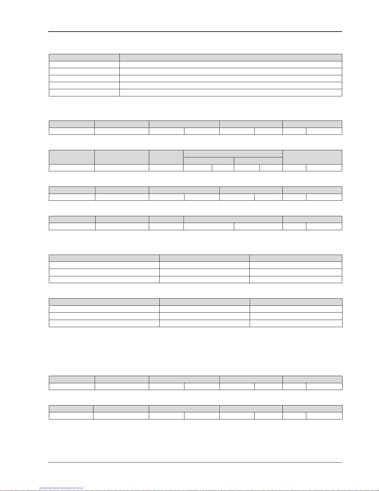
54 Appendix 2 Modbus Communication Protocol
EV3200 Door Control Inverter User Manual
If the operation fails, error code and exception code forming the protocol data unit will be replied. The error code is (Parameter
+ 0x80). The exception code denotes cause of the error; see the table below.
Exception code Meaning
0x03 Data error, exceeding upper or lower limit
0x18 Information frame error, including data length or check sum error
0x20 Parameter cannot be modified
0x21 Parameter cannot be modified during operation
0x22 Parameter protected by password
Example:
Request frame: read two function parameters, F0.01 as the initial address.
Address Function parameter Register address Quantity of inputs Check sum
0x01 0x03 0x00 0x01 0x00 0x02 0x95 0xCB
Response frame: read two function parameters, from high to low, that is, from F0.02 to F0.01
Content of inputs
Address Function parameter Bytes
F0.02 F0.01
Check sum
0x01 0x03 0x04 0x00 0x03 0x00 0x01 0x0A 0x33
Request frame: read 3305 DC bus voltage status parameter
Address Function parameter Register address Quantity of inputs Check sum
0x01 0x03 0x33 0x05 0x00 0x01 0x9B 0x4F
Response frame:
Address Function parameter Bytes Content of inputs Check sum
0x01 0x03 0x02 0x01 0x47 0XF9 0xE6
Protocol data unit format of modifying single inverter’s parameters:
Request format:
Protocol data unit Data length (bytes) Range
Function parameter 1 0x06
Register address 2 0x0000 ~ 0xFFFF
Register content 2 0x0000 ~ 0xFFFF
Response format:
Protocol data unit Data length (bytes) Range
Function parameter 1 0x06
Register address 2 0x0000 ~ 0xFFFF
Register content 2 0x0000 ~ 0xFFFF
For modifying single inverter’s parameters, the request frame is the same as the response frame: If the operation fails, error
code and exception code forming the protocol data unit will be replied. The error code is (Parameter + 0x80). For the error
code, refer to the above description.
Example:
Request frame: change F0.02 setting to 3.
Address Function parameter Register address Register content Check sum
0x05 0x06 0x00 0x02 0x00 0x03 0x69 0x8F
Response frame: setting change success, return to original value
Address Function parameter Register address Register content Check sum
0x01 0x06 0x00 0x02 0x00 0x03 0x69 0x8F
Parameter 0x41 is to modify single inverter’ parameter or control parameter and save it in a non-volatile memory. The format
is similar to that of 0x06. The only difference is that 0x41 parameter is saved upon power failure, while 0x06 not.
Protocol data unit format of modifying several inverter’s parameters:
Page 59

Appendix 2 Modbus Communication Protocol 55
EV3200 Door Control Inverter User Manual
Request format:
Protocol data unit Data length (bytes) Range
Function parameter 1 0x06
Initial register address 2 0x0000 ~ 0xFFFF
Operation register quantity 2 0x0000 ~ 0x016
Register bytes number 1 2* operation register quantity
Register contents 2*operation register quantity
Depending on parameter range
Response format:
Protocol data unit Data length (bytes) Range
Function parameter 1 0x06
Register address 2 0x0000 ~ 0xFFFF
Operation register quantity 2 0x0000 ~ 0x016
Example:
Request frame: initial address F1.01, change two function parameters, the change contents in the sequence from low to high,
as in the table below.
Modification contents
Address
Function
parameter
Initial
address
Register quantity Bytes
F1.01 F1.02
Check sum
05 10 01 01 00 02 04 00 64 02 58 68 86
Response frame:
Address Function parameter Register address Register quantity Check sum
0x05 0x10 0x01 0x01 0x00 0x02 0x10 0x70
In RTU mode, when changing multiple function parameters, the max number is 22. In ASCII mode, the max number is halved.
If the operation request fails, error code and exception code forming the protocol data unit will be replied. The error code is
(Parameter + 0x80). For the error code, refer to the above description.
Modbus error detection mechanism:
Check sum of ASCII mode: LRC check sum covers the information part from slave address to data, equal to the complement
the of sum of the check data characters. For example: The complement of (01H+06H+00H+03H+03H+0xE8H) is 0AH。
Check sum of RTU mode: CRC-16 check sum covers information from slave address to data. The calculation is shown below:
unsigned int crc_check (unsigned char *data, unsigned char length)
{
int i;
unsigned crc_result=0xffff;
while(length--)
{
crc_result^=*data++;
for(i=0;i<8;i++)
{
if(crc_result&0x01)
crc_result=(crc_result>>1)^0xa001;
else
crc_result=crc_result>>1;
}
}
return (crc_result=((crc_result&0xff)<<8)|(crc_result>>8));}
Page 60

56 Appendix 3 EU Declaration of Conformity
EV3200 Door Control Inverter User Manual
Appendix 3 EU Declaration Of Conformity
According to the Low Voltage Directive 2006/95/EC
with the Amendment Directive 93/68/EEC and the Directive for Electromagnetic Compatibility
89/336/EEC
For the following equipment:
Product :
Adjustable Speed Drive
Type Designation/Trademark :
EV3200-2S0004A/ 2S0002A/ 2S0004S/ 2S0002S
Manufacturer’s Name :
Emerson Network Power Co. Ltd
Manufacturer’s Address :
No.1 Kefa Road, Science & Industry Park, Nanshan District,
Shenzhen, 518057, China
is herewith confirmed to comply with the requirements set out in the Council Directive 2006/95/EC for electrical equipment
used within certain voltage limits and the Amendment Directive 93/68/EEC and with the requirements of the Directive
89/336/EEC. For the evaluation of the compliance with this Directives, the following standards were applied:
EN61800-5-1:2003 Adjustable speed electrical power drive system
Part 5-1 Safety requirements-Electrical, thermal and energy
EN61800-3:2004 Adjustable speed electrical power drive system
Part 3: EMC requirements and specific test methods
LVD Compliance technical report issued by Emerson Network Power Co. Ltd, report number: F3AS241AZ&
F3AS221AZ&F3AS241SZ&F3AS221SZ -TSR-2V1, dated Jun. 21, 2007.
EMC Compliance technical report issued by Emerson Network Power Co. Ltd, report number:
EV3200-F3AS241AZ&F3AS221AZ&F3AS241SZ&F3AS221SZ-TCC-2V1, dated May 30, 2007.
Responsible for making this declaration is the manufacturer.
Person responsible for making this declaration
Name, Surname : Weiguo Zeng
Position/Title : Director, Test Dept of R&D
2007-06-21
Signature Date
Page 61
Emerson Network Power Co. Ltd.
Maintenance Record (1)
Customer’s company:
Address:
Post Code: Contact person:
Tel: Fax:
Drive’s SN:
Power: Model:
Contract number: Purchasing Date:
Service provider:
Contact person: Tel:
Servicing engineer: Tel:
Maintenance date:
Customer’s comments on service quality:
□
Excellent
□
Satisfactory
□
Acceptable
□
Unsatisfactory
Other Opinions:
Signature: DD MM YYYY
Visiting Record of Customer Service Center:
□
by phone-calls
□
by questionnaire
Others:
Signature: DD MM YYYY(date)
Note: This paper becomes invalid if the user cannot be revisited!
Emerson Network Power Co. Ltd.
Maintenance Record (2)
Customer’s company:
Address
Post Code: Contact person:
Tel: Fax:
Drive’s SN:
Power: Model:
Contract NO. Purchasing Date:
Service provider:
Contact person: Tel:
Servicing person : Tel:
Maintenance date:
Customer’s comments on service quality:
□
Excellent
□
Satisfactory
□
Acceptable
□
Unsatisfactory
Other Opinions:
User’s Signature: DD MM YYYY
Visiting Record of Customer Service Center:
□
by phone-calls
□
by questionnaire
Others:
Signature: DD MM YYYY(date)
Note: This paper becomes invalid if the user cannot be revisited!
Page 62

Notice
1. The warranty range is confined to the inverter only.
2. Warranty period is 18 months, within which period Emerson Network
Power conducts free maintenance and repairing to the drive that has any fault
or damage under the normal operation conditions.
3. The start time of warranty period is the delivery date of the product
, of
which the product SN is the sole basis of judgment. Inverters without a product
SN shall be regarded as out of warranty.
4. Even within 18 months, maintenance will also be charged in the following
situations:
Damages incurred to the drive due to mis-operations, which are not in
compliance with the User Manual;
Damages incurred to the drive due to fire, flood, abnormal voltage, etc;
Damages incurred to the drive due to the improper use of inverter
functions.
5. The service fee will be charged according to the actual costs. If there is any
contract, the contract prevails.
6. Please keep this paper and show this paper to the maintenance unit when
the product needs to be repaired.
7. If you have any question, please contact the distributor or our company
directly.
ENP Services China
Emerson Network Power Co., Ltd.
Address: No.1 Kefa Rd., Science & Industry Park, Nanshan District, 518057,
Shenzhen, PRC
Customer Service Hotline: +86 755 86010537, 400-887-6510
Complaint Hotline: +86 755 86010800
Notice
1. The warranty range is confined to the inverter only.
2. Warranty period is 18 months, within which period Emerson Network
Power conducts free maintenance and repairing to the drive that has any fault
or damage under the normal operation conditions.
3. The start time of warranty period is the delivery date of the product
, of
which the product SN is the sole basis of judgment. Inverters without a product
SN shall be regarded as out of warranty.
4. Even within 18 months, maintenance should also be charged in case of the
following situations:
Damages incurred to the drive due to mis-operations which are not in
compliance with the User Manual;
Damages incurred to the drive due to fire, flood, abnormal voltage, etc;
Damages incurred to the drive due to the improper use of inverter
functions.
5. The service fee will be charged according to the actual costs. If there is any
contract, the contract prevails.
6. Please keep this paper and show this paper to the maintenance unit when
the product needs to be repaired.
7. If you have any question, please contact the distributor or our company
directly.
ENP Services China
Emerson Network Power Co., Ltd.
Address: No.1 Kefa Rd., Science & Industry Park, Nanshan District, 518057,
Shenzhen, PRC
Customer Service Hotline: +86 755 86010537, 400-887-6510
Complaint Hotline: +86 755 86010800
Page 63

To Customers:
Thank you for choosing our products. We are expecting your comments about the quality of the products, so that we can
improve our work and serve you better. We really appreciate if you would fill in the form after the product has operated for 1
month, and then mail or fax it to the Customer Service Center of Emerson Network Power. We will send you an exquisite
souvenir upon the receipt of the completed Product Quality Feedback Paper. You will receive a special gift if you can give us
any advices on improving the product and service quality.
Customer Service Dept
Emerson Network Power Co., Ltd.
Product Quality Feedback Form
User’s name Tel:
Address Post code
Product model Installation date
Product SN
Product outline or
structure
Product
performance
Product package
Product manual
Product quality
condition in using
Your advices on
product
improvement
Address: No.1 Kefa Rd., Science & Industry Park, Nanshan District, 518057, Shenzhen, PRC
Tel: +86 755 86010581
 Loading...