

Page 1
Instruction Manual
ETC00303
02/2007
Instruction Manual
BINOS® E
Economic & Enhanced Gas Analyzer
rd
3
Edition 02/2007
www.EmersonProcess.com
Page 2

BINOS® E Instruction Manual
ETC00303
02/2007
ESSENTIAL INSTRUCTIONS
READ THIS P AGE BEFORE PROCEEDING!
Emerson Process Management (Rosemount Analytical) designs, manufactures and test s
its products to meet many national and international standards. Because these instruments
are sophisticated technical products, you MUST properly install, use, and maintain
them to ensure they continue to operate within their normal specifications. The following
instructions MUST be adhered to and integrated into your safety program when installing,
using and maintaining Emerson Process Management (Rosemount Analytical) products.
Failure to follow the proper instructions may cause any one of the following situations to
occur: Loss of life; personal injury; property damage; damage to this instrument; and warranty
invalidation.
• Read all instructions prior to installing, operating, and servicing the product.
• If you do not understand any of the instructions, contact your Emerson Process
Management (Rosemount Analytical) representative for clarification.
• Follow all warnings, cautions, and instructions marked on and supplied with the product.
• Inform and educate your personnel in the proper installation, operation, and
maintenance of the product.
• Install your equipment as specified in the Installation Instructions of the appropriate
Instruction Manual and per applicable local and national codes. Connect all products
to the proper electrical and pressure sources.
• T o ensure proper performance, use qualified personnel to install, operate, update, program,
and maintain the product.
• When replacement parts are required, ensure that qualified people use replacement parts
specified by Emerson Process Management (Rosemount Analytical). Unauthorized parts
and procedures can affect the product’s performance, place the safe operation of your
process at risk, and VOID YOUR W ARRANTY. Look-alike substitutions may result in fire,
electrical hazards, or improper operation.
• Ensure that all equipment doors are closed and protective covers are in place, except
when maintenance is being performed by qualified persons, to prevent electrical
shock and personal injury.
The information contained in this document is subject to change without notice. Misprints
reserved.
1st Edition 11/2000 2nd Edition 05/2001
3rd Edition 02/2007
© 2000-2007 by Emerson Process Management
Emerson Process Management
GmbH & Co. OHG
Industriestrasse 1
D-63594 Hasselroth
Germany
T +49 (0) 6055 884-0
F +49 (0) 6055 884-209
Internet: www.EmersonProcess.com
Page 3

Rosemount Analytical
CONTENTS
Table of Contents
SAFETY SUMMARY S - 1
General S - 2
Gases and Gas Conditioning (Sample Handling) S - 4
Supply Voltage S - 4
BINOS E specific notes for the user S - 5
Additional notes for service / maintenance S - 6
Electrostatic Discharge S - 7
PREFACE P - 1
DESCRIPTION
1. Technical Description 1 - 1
1.1 Front Panel 1 - 1
1.2 Rear Panel 1 - 4
1.3 Internal Construction (Component Layout) 1 - 5
1.3.1 Internal Gas Paths 1 - 7
1.3.2 Printed Circuit Boards 1 - 9
2. Measuring Principle 2 - 1
2.1 NDIR Measurement 2 - 1
2.1.1 Opto - Pneumatic Measuring Principle 2 - 3
2.1.2 Interference Filter Correlation (IFC Principle) 2 - 4
2.2 NDUV Measurement 2 - 6
2.3 Oxygen Measurement 2 - 7
2.3.1 Paramagnetic Measurement 2 - 7
2.3.2 Electrochemical Measurement 2 - 9
2.4 (Vacant) 2 - 11
3. (vacant)
4. (vacant)
ETC00303(1) BINOS E e (2.0) 11/00
I
Page 4

CONTENTS
OPERATION (STARTUP)
5. Installation and Preparation of Startup 5 - 1
5.1 Installation Site 5 - 2
5.2 (vacant) 5 - 3
5.2.1 Pressure Sensor (Option) 5 - 4
5.2.4 Gas Flow 5 - 4
5.3 Gas Connections 5 - 5
6. Startup Procedue (Switching On) 6 - 1
6.1 Supply Voltage 6 - 2
7. Measurement / Calibration / Switching (Shut) Off 7 - 1
7.1 Measurement 7 - 1
7.2 Calibration 7 - 2
7.2.1 Calibration (Test) Gases 7 - 2
7.3 Switching (Shut) Off 7 - 4
Rosemount Analytical
8. BINOS E Front Panel Program 8 - 1
8.1 Requirements 8 - 1
8.2 Installation and Startup 8 - 2
8.2.1 Installation 8 - 2
8.2.2 Startup 8 - 4
8.3 Function Keys 8 - 4
8.4 Status Display ("Status") 8 - 10
8.5 Display Page 8 - 11
8.6 Recorder Page 8 - 14
8.6.1 Averaging 8 - 15
8.6.2 Spooling 8 - 15
8.6.3 Recording 8 - 15
8.7 Messages Page 8 - 16
8.8 Analog Output Link and Adjustment Page 8 - 18
9. BINOS E Data Exchange 9 - 1
II
ETC00303(1) BINOS E e (2.0) 11/00
Page 5

Rosemount Analytical
10. TROUBLESHOOTING
10.1 (vacant)
11. Test Procedure / Test Points (vacant)
12. Removal / Replacement of Components (vacant)
13. MAINTENANCE 13 - 1
14. Leak Testing 14 - 1
CONTENTS
15. Opening the Housing 15 - 1
15.1 BINOS E (Metal-sheet housing) 15 - 1
15.1.1 Housing Cover 15 - 1
15.2 BINOS E (1/2 19" housing) 15 - 2
15.2.1 Housing Cover 15 - 2
16. (vacant)
17. Replacement and Cleaning of Photometric Components 17 - 1
17.1 Removal of the Photometer Assembly 17 - 1
17.2 Light Source Replacement (IR) 17 - 2
17.3 Cleaning of Analysis Cells and Windows 17 - 3
17.3.1 Removal of Analysis Cells 17 - 3
17.3.2 Cleaning 17 - 4
17.3.3 Reinstalling of Analysis Cells 17 - 5
17.4 Reinstalling of the Photometer Assembly 17 - 6
17.5 Physical Zeroing 17 - 7
18. Check / Replacement of electrochemical Oxygen Sensor 18 - 1
18.1 Check of the Sensor 18 - 2
18.2 Replacement of the Sensor 18 - 3
18.2.1 Removal of the Sensor 18 - 3
18.2.2 Replacing the Sensor 18 - 4
18.2.3 Reinstalling of the Sensor 18 - 4
18.2.4 Basic conditions for the Oxygen Sensor 18 - 5
19. Cleaning of Housing Outside 19 - 1
ETC00303(1) BINOS E e (2.0) 11/00
III
Page 6

CONTENTS
Rosemount Analytical
20. TECHNICAL DATA 20 - 1
20.1 Housing 20 - 1
20.2 Options 20 - 2
20.3 General Specifications 20 - 2
20.3.1 BINOS E Specifications 20 - 3
20.3.2 Cross Sensitivities 20 - 4
20.3.3 Dimensions 20 - 5
20.4 Voltage supply 20 - 6
20.4.1 Electrical Safety 20 - 6
20.4.2 Power Supply 20 - 6
SUPPLEMENT
21. Pin Assignments 21 - 1
21.1 24 V dc Input 21 - 1
21.2 Serial Interfaces (vacant) 21 - 2
21.3 Analog Signal Outputs (vacant) 21 - 2
22. Calculation of Water Content from Dew-Point 22 - 1
to Vol.-% or g/Nm
3
IV
ETC00303(1) BINOS E e (2.0) 11/00
Page 7
Rosemount Analytical
SAFETY SUMMARY
Safety Summary
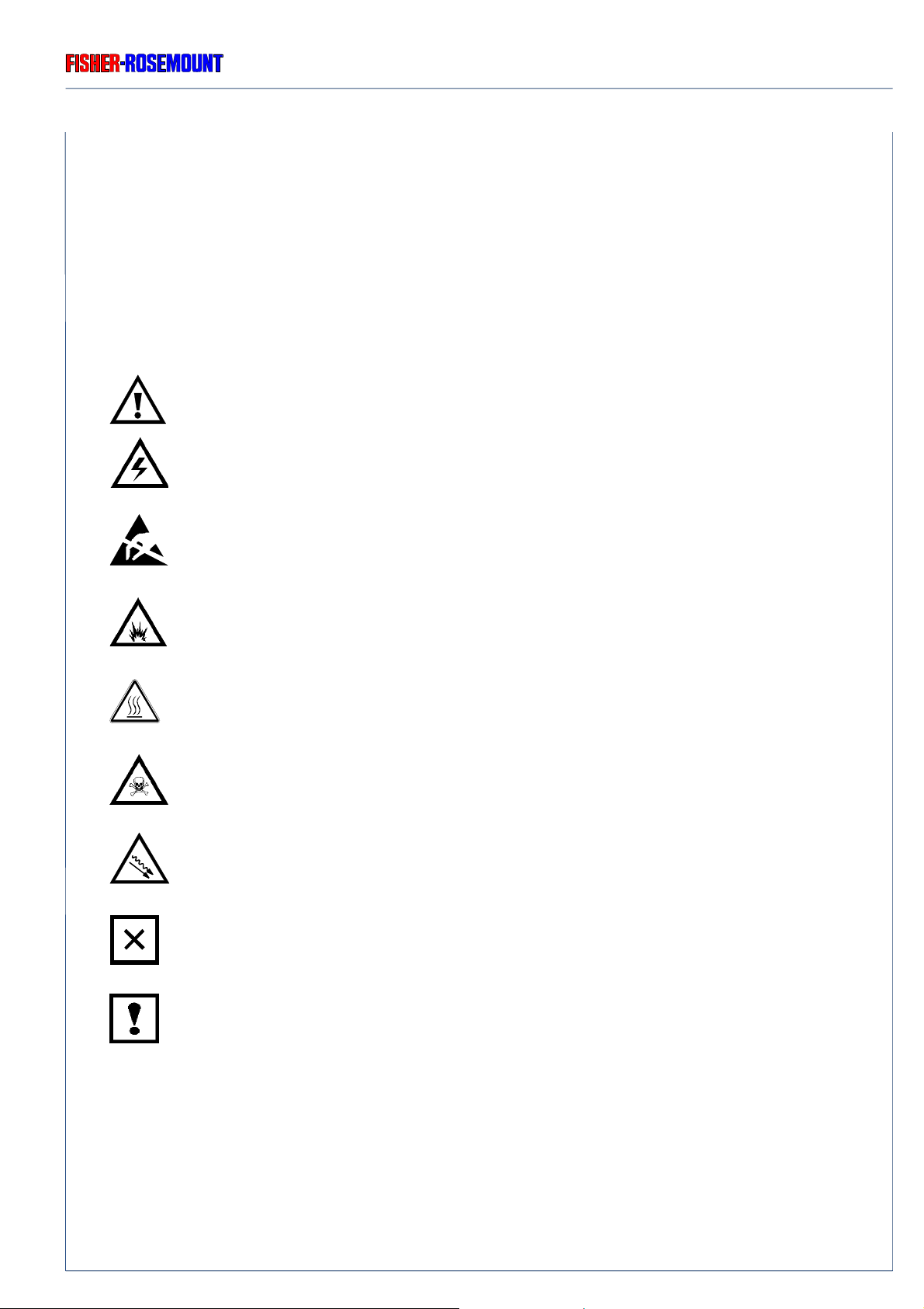
Outside and/or inside BINOS E or at operation manual resp . diff erent symbols gives you a hint
to special sources of danger.
Source of danger !
See Operation Manual!
High V oltage !
GENERAL
Electrostatic Discharge (ESD) !
Explosives !
Hot components !
Toxic !
UV Radiation !
Risk to health !
BINOS E specific notes for the user !
In operation manual we will give partly additional informations to these symbols.
Strictly follow these instructions please !
ETC00303(1) BINOS E e (2.0) 11/00
S - 1
Page 8

SAFETY SUMMARY
GENERAL
Rosemount Analytical
1. General
◆ The following gener al safety precautions must be observed during all phases of operation,
service and repair of this instrument !
Failure to comply with these precautions or with specific warnings elsewhere in this manual
violates safety standards of design, manufacture and intended use of this instrument !
F ailure to comply with these precautions may lead to personal injury and damage to this
instrument !
◆ Fisher-Rosemount GmbH & Co. does not tak e responsibility (liability) for the customer´s
failure to comply with these requirements !
◆ Do not attempt internal service or adjustment unless other person, capable of rendering first
aid and resuscitation, is present !
◆ Because of the danger of introducing additional hazards, do not perfo rm any unauthorized
modification to the instrument !
Return the instrument to a Fisher-Rosemount Sales and Service office for service or repair
to ensure that safety features are maintained !
◆ Instruments which appear damaged or defective should be made inoper ative and secured
against unintended operation until they can be repaired b y qualified service personnel.
S - 2
ETC00303(1) BINOS E e (2.0) 11/00
Page 9
Rosemount Analytical
SAFETY SUMMARY
GENERAL
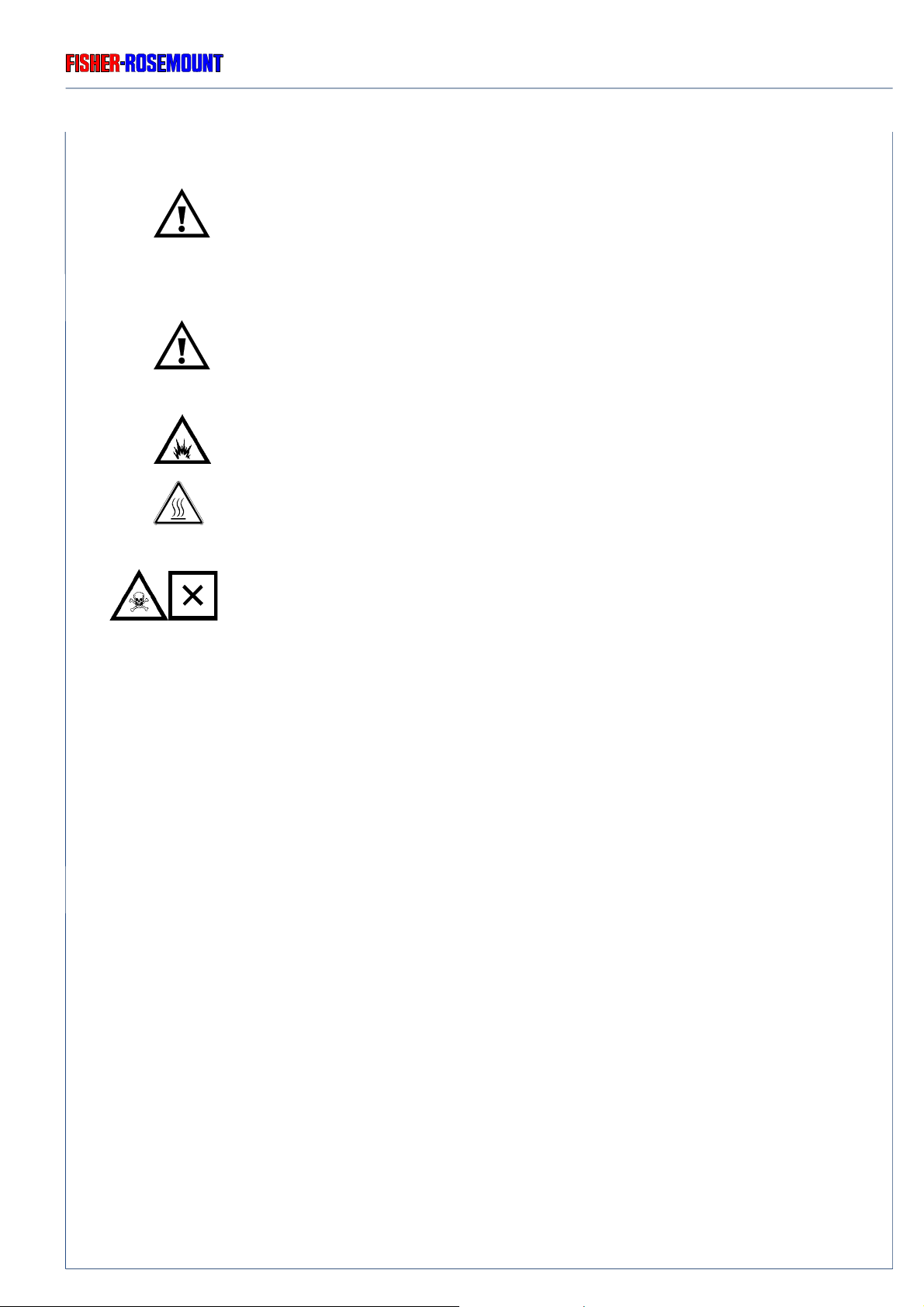
Operating personnel must not remove instrument covers !
Component replacement and internal adjustments must be made by qualified
service personnel only !
Read and understand all operation manuals and receiving appropriate training
before attempting to operate with the instrument !
Be sure to observe the additional notes, saf ety precautions and warnings given
in the individual operation manuals !
Do not operate the instrument in the presence of flammable gases or explosiv e
atmosphere without supplementary protective measures !
At photometer or heated components there could be exist hot components !
The optional UV lamp contains mercury. Lamp breakage could result in mercury
exposure ! Mercury is highly toxic !
If the lamp is broken, avoid any skin contact to mercury and inhalation of mercury
vapors !
ETC00303(1) BINOS E e (2.0) 11/00
S - 3
Page 10
SAFETY SUMMARY
GASES AND GAS CONDITIONING (SAMPLE HANDLING) / SUPPLY VOLTAGE
2. Gases and Gas Conditioning (Sample Handling)
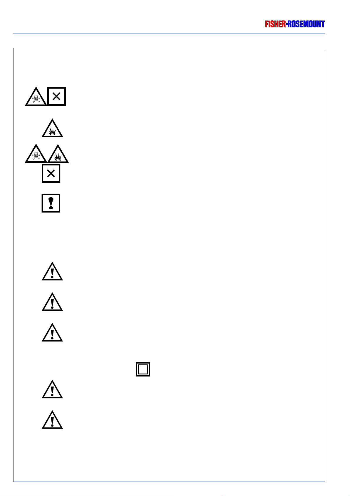
Be sure to observe the safety regulations for the respective gases
(sample gas and test gases / span gases) and the gas bottles !
Flammable or e xplosive gas mixtures must not be purged into the instrument
without supplementary protective measures !
To avoid a danger to the operators by explosive, toxic or unhealthy gas
components, first purge the gas lines with ambient air or nitrogen (N2) before
cleaning or exchange parts of the gas paths.
Rosemount Analytical
Pressure of sample gas / test gases max. 1,500 hPa !
3. Supply Voltage
The socket outlet shall be installed near the equipment and shall be easily
accessible to disconnect the device from the socket outlet.
Verify whether the line voltage stated on the instrument ore power supply agrees
with that of your mains line!
Be sure to observe the safety precautions and warnings given by
manufacturer of power supply !
◆ BINOS E is a Safety Class 2 ( ) instrument.
S - 4
Verify correct polarity for 24 V dc operation !
Use only power supply UPS 01 T, SL5, SL10 (SL 5/10 for cabinet mounting
only) or equivalent pow er supplys to be in agreement with the CE conformity.
ETC00303(1) BINOS E e (2.0) 11/00
Page 11
Rosemount Analytical
4. BINOS E specific notes for the user
Before startup unscrew transfer safety lock (knurled-head screws)
of the BINOS E (Item 5. of operation manual) !
The installation site for the instrument has to be dry and remain above freezing
point at all times.
The instrument must be exposed neither to direct sunlight nor to strong sources
of heat. Be sure to observe the permissible ambient temperature !
For outdoor sites, we recommend to install the instrument in a protective cabinet.
At least, the instrument has to be protected against rain (e.g., shelter).
SAFETY SUMMARY
BINOS E SPECIFIC NOTES FOR THE USER
Free flow of air into and out of the BINOS E (ventilation slits) must not be
hindered by nearby objects or walls !
Do not interchange gas inlets and gas outlets !
All gases have to be supplied to the BINOS E as conditioned gases !
When the instrument is used with corrosive gases, it is to be verified that there
are no gas components which may damage the gas path components.
The exhaust gas lines have to be mounted in a declining, descending,
pressureless and frost-free and according to the valid emission legislation !
In case it is necessary to open the gas paths, close the analyzers
gas connections with PVC caps immediatly !
Pressure of sample gas / test gases max. 1,500 hPa !
By using of optional delivering terminal strip adapters with BINOS E the
analyzer is not be in agreement with the CE conformity. In this case CE
conformity has to be declared by customer as “manufacturer of system”.
Use only optional delivered cables from our factory or equivalent shielded
cables to be in agreement with CE conformity.
The customer has to prove that the shield is connected on both sides.
Shield and connectors housing has to be connected conductive.
Sub.-min.-D-plugs/sockets have to be screwed to the analyzer.
ETC00303(1) BINOS E e (2.0) 11/00
S - 5
Page 12

SAFETY SUMMARY
ADDITIONAL NOTES FOR SERVICE / MAINTENANCE
5. Additional notes for service / maintenance
Operating personnel must not remove instrument covers !
Component replacement and internal adjustments must be made by qualified
service personnel only !
Always disconnect power, discharge circuits and remove external voltage
sources before troubleshooting, repair or replacement of any component !
Any work inside the instrument without switching off the power must be
performed by a specialist, who is familiar with the related danger, only !
Rosemount Analytical
To avoid a danger to the operators by explosive, toxic or unhealthy gas
components, first purge the gas lines with ambient air or nitrogen (N2) before
cleaning or exchange parts of the gas paths.
At photometer or heated components there could be exist hot components !
In case of exchanging fuses the customer has to be certain that fuses of specified
type and rated current are used. It is prohibited to use repaired fuses or defective
fuse holders or to short-circuit fuse carriers (fire hazard).
UV source operates with high voltage !
[Voltage supply UVS (Fig. 1-3)]
Ultraviolet light from UV lamp can cause permanent eye damage !
Do not look directly at the ultraviolet source !
S - 6
At component replacement or installation the RF shielding contacts must not
be bended !
ETC00303(1) BINOS E e (2.0) 11/00
Page 13

Rosemount Analytical
ELECTROSTATIC DISCHARGE
SAFETY SUMMARY
6 Electrostatic Discharge
The electronic parts of the analyzer can be irreparably damaged if exposed to electrostatic
discharge (ESD).
The instrument is ESD protected when the covers hav e been secured and safety precautions
observed. When the housing is open, the internal components are not ESD protected anymore.
Although the electronic parts are reasonable safe to handle, you should be aware of the
following considerations:
Best ESD example is when you walked across a carpet and then touched an electrical
grounded metal doorknob. The tiny spark which has jumped is the result of electrostatic
discharge (ESD).
You prevent ESD by doing the following:
Remove the charge from y our body before opening the housing and maintain during work with
opened housing, that no electrostatic charge can be built up.
Ideally you are opening the housing and working at an ESD - protecting workstation.
Here you can wear a wrist trap.
Howe ver , if you do not ha ve such a workstation, be sure to do the follo wing procedure exactly:
Discharge the electric charge from your body. Do this by touching a device that is grounded
electrically (any device that has a three - prong plug is grounded electrically when it is plugged
into a power receptacle).
This should be done sev eral times during the operation with opened housing (especially after
leaving the service site because the movement on a low conducting floors or in the air might
cause additional ESDs).
ETC00303(1) BINOS E e (2.0) 11/00
S - 7
Page 14

SAFETY SUMMARY
Rosemount Analytical
S - 8
ETC00303(1) BINOS E e (2.0) 11/00
Page 15

Rosemount Analytical
Preface
The BINOS E analyzers offer multi-component, multi-method analysis. Different measurement
methods can be combined in one analyzer.
BINOS E is designed to measure up to max. 4 gas components and up to 8 secondary
parameters (pressure, temperature and flow). Primary measurements include photometer
and non-photometer-channels (possible combinations: see price matrix):
- Non-dispersive Infrared (up to two channels)
- Non-dispersive Ultraviolet (one channel)
- Paramagnetic Oxygen (up to two channels)
PREFACE
- Electrochemical Oxygen (up to two channels)
BINOS E can combine up to two photometer and up to two non-photometer channels.
BINOS E is designed for OEM customers, for bench and sensor integrators, f or universities and
institutes. That means for anybody who likes a modern new measuring philosophy with
communication via serial interface.
System builders create their own Control Units or Platforms. They need either high performance optical or sensor benches (fast response, lo w ranges and/or high dynamic measurements) or robust photometer/sensor technologies but with no need f or an instrument displa y.
There is also no need for digital inputs or outputs, often e ven no necessity f or analog outputs.
That is why BINOS E offers as a standard only communication via serial interface. Analog
outputs are available as option. Relay contacts, digital inputs and outputs are not provided.
Main applications for BINOS E are:
- Automotive (Internal Combustion Engine Emissions, ICEE)
- Fast response capnography (Lung function tests)
- Solids Analyzers (C, S, H, N analysis)
- TOC/ TN/ TS Analyzers (Total organic carbon, nitrogen or sulphur)
- Metallurgical Business (Oven atmosphere, hardening, ceramic)
BINOS E is specially designed to measure high dynamic ranges such as low carbon mono xide
concentrations for automotive applications combined with other measurements:
CO
: 0 - 50 ... 5,000 ppm
low
CO
: 0 - 0.5(1) ... 10 Vol.-%
high
CO2: 0 - 1 ... 16 (20) Vol.-%
O2: 0 - 1 (2) ... 10 (25) Vol.-%
ETC00303(1) BINOS E e (2.0) 11/00
P - 1
Page 16

PREFACE
Rosemount Analytical
An additional NO, SO2 or C6H14 channels are av ailable as option for automotiv e applications:
NO: 0 - 250 ... 2,500 ppm
SO2: 0 - 130 ... 3,000 ppm (NDUV)
C
: 0 - 300 ... 3,000 ppm
6H14
NO2: 0 - 250 ... 1,000 ppm (NDUV)
For medical application we offer CO and CH4 with IFC principles:
CO: 0 - 3,000 ppm
CH4: 0 - 3,000 ppm
Solids analyzers can be equipped with:
CO: 0 - 1 ... 10 Vol.-%
CO2: 0 - 1 ... 16 (20) Vol.-%
SO2: 0 - 1 ... 10 Vol.-%
H2O: 0 - 1 ... 3(4) Vol.-%
For T OC/ TN/ TS applications we can provide:
CO2: 0 - 1 ... 16 (20) Vol.-% or 0 - 100 (200) ... 2,000 (3,000) ppm
NO: 0 - 250 ... 2,500 ppm
SO2: 0 - 130 ... 3,000 ppm (NDUV)
For metallurgical applications we offer:
CO: 0 - 1 ... 20 Vol.-% or 0 - 20 ... 100 Vol.-%
CO2: 0 - 5 ... 100 Vol.-%
This is an overview about main applications with main configurations/components. Other
components and applications may be provided on request.
The following list of abbreviations gives an overview about terms used in this manual:
IR = measurement at infrared spectral range
UV = measurement at ultraviolet spectral range
VIS = measurement at visual spectral range
PO2= paramagnetic oxygen measurement
EO2= electrochemical oxygen measurement
P - 2
ETC00303(1) BINOS E e (2.0) 11/00
Page 17

Rosemount Analytical
TECHNICAL DESCRIPTION
FRONT PANEL
1. Technical Description
BINOS E is different from common gas analyzers as follows:
The BINOS E analyzer is assembled as a b lind instrument without need of anoperation front
panel.
Communication is done via serial interface RS 232 with the Fisher-Rosemount Front Panel
Program (option) or via DPS protocol to support a user designed program.
The Front P anel Program is described in chapter 8 while chapter 9 gives information about the
DSP protocol.
Compared with NGA 2000 ML T 1 the A CU (analyzer control unit) is missing and the cardcage
is modified by replacing the optional PCB's SIO, DIO and LEM (network board) with a new
I/O board LIO (low cost I/O). Thus, BINOS E is a stand-alone analzer without network
functionality. The operation procedure is performed by an external PC via serial interface.
All components of a BINOS E analyzer are incorporated into a metal-sheet housing or a 1/2
19" housing.
The 1/2 19" housings are available as rack-mounting or tab le-top versions.
1.1 Front Panel
The front panel of the BINOS E analyzer shows a blind plate instead of an operation front panel.
The 1/2 19" housing front panel is shown in Fig. 1-1(rack-mountable version).
The metal-sheet versions have a blind plate too (see Fig. 1-2).
No electrical and gas connections are realized from the front panel.
At BINOS E front panel rear side (see Fig. 1-3) there are mounted different components if the
corresponding options are chosen.
ETC00303(1) BINOS E e (2.0) 11/00
1 - 1
Page 18
TECHNICAL DESCRIPTION
FRONT PANEL
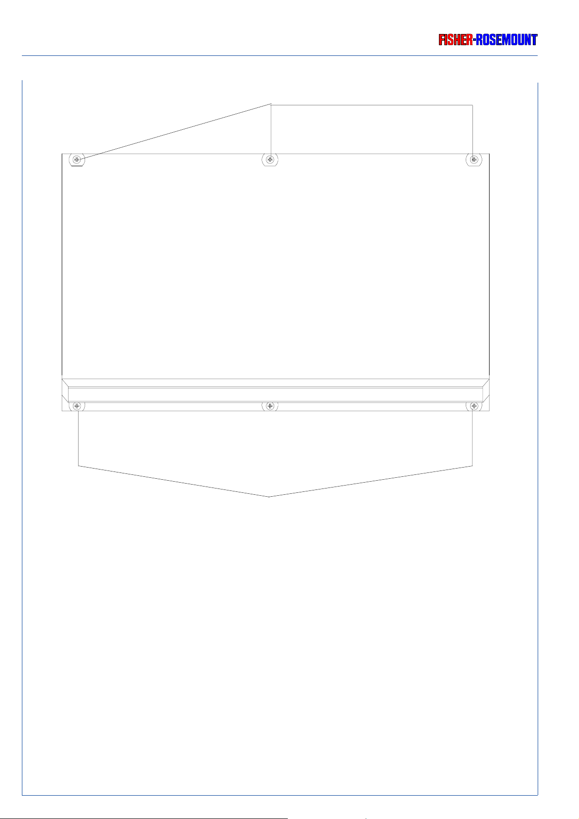
Fastening screws for rack mounting or carrying-strap bracket
Rosemount Analytical
1 - 2
Fastening screws for rack mounting or carrying-strap bracket
Fig. 1-1: BINOS E front panel, Front view
ETC00303(1) BINOS E e (2.0) 11/00
Page 19
Rosemount Analytical
TECHNICAL DESCRIPTION
FRONT PANEL
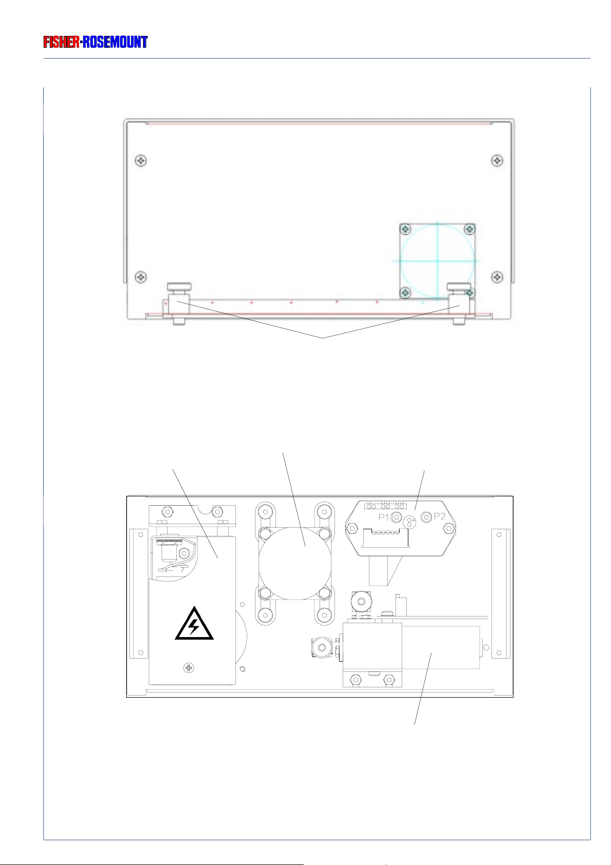
Fig. 1-2: BINOS E Sheet-metal Housing , Front panel, Front view
UVS (Voltage Supply for UV Source)
[Option]
Retention pins
Fan [depending on
configuration]
Pressure Sensor
[Option]
OUT
ETC00303(1) BINOS E e (2.0) 11/00
IN
O2 Sensor, electrochemical
[Option]
Fig. 1-3: BINOS E, Front panel, Rear view
1 - 3
Page 20
TECHNICAL DESCRIPTION
REAR PANEL
Rosemount Analytical
1.2 Rear Panel
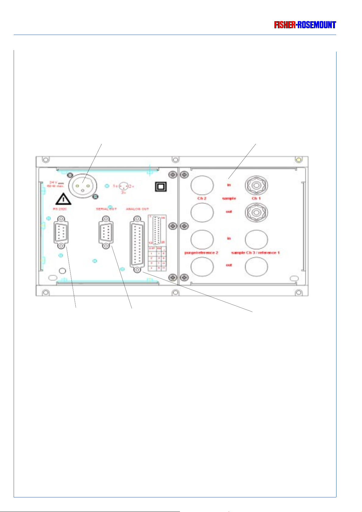
On the BINOS E rear panel the connector for 24 Vdc supply, the gas connections and the
connectors for Input/output modules (standard and optional I/O's) are accommodated.
Input 24 V dc Gas connections
Serial Interface RS 232
(Standard)
Serial out: RS 232 or CAN open
(Option)
Fig. 1-4: BINOS E, Rear panel (including all options)
4 Analog Outputs
(Option)
1 - 4
ETC00303(1) BINOS E e (2.0) 11/00
Page 21
Rosemount Analytical
TECHNICAL DESCRIPTION
INTERNAL CONSTRUCTION
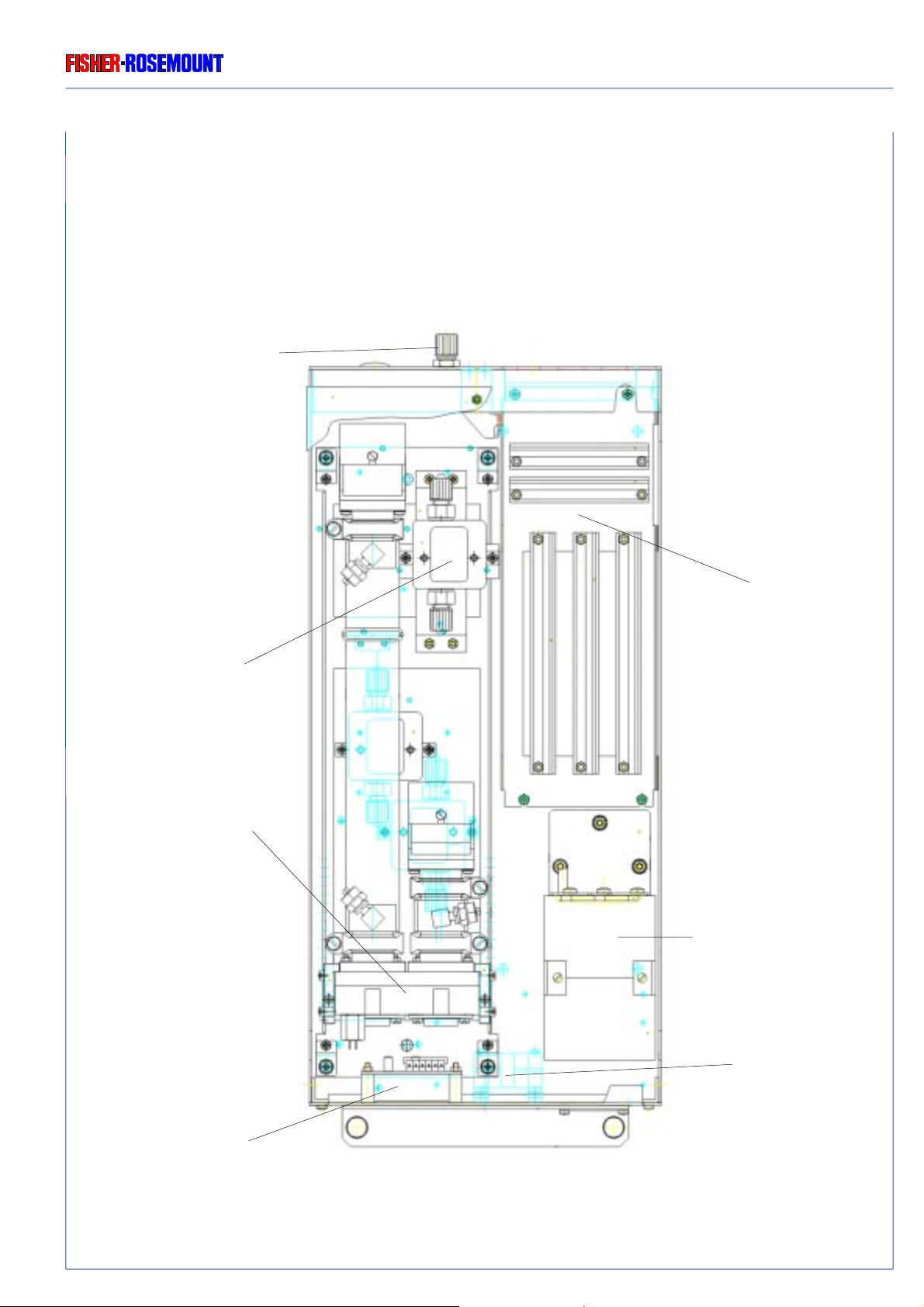
1.3 Internal Construction (Component Layout)
Regarding BINOS E from the front, the electronic unit with interconnection PCB and other
PCBs are located on the right. The photometer assembly and other parts are located on the
left.
Gas Connections
Flow Sensor
(Option)
Photometer Bench with
Gas Detectors
(single or dual channel
assembly)
Card Cage
(see Item 1.3.2)
O2 Sensor, paramagnetic
(Option)
Pressure Sensor
(Option)
ETC00303(1) BINOS E e (2.0) 11/00
Fan
Fig. 1-5: BINOS E, Sheet-metal Housing, Top view
(with 2 NDIR channels & paramagnetic O2 Sensor)
1 - 5
Page 22
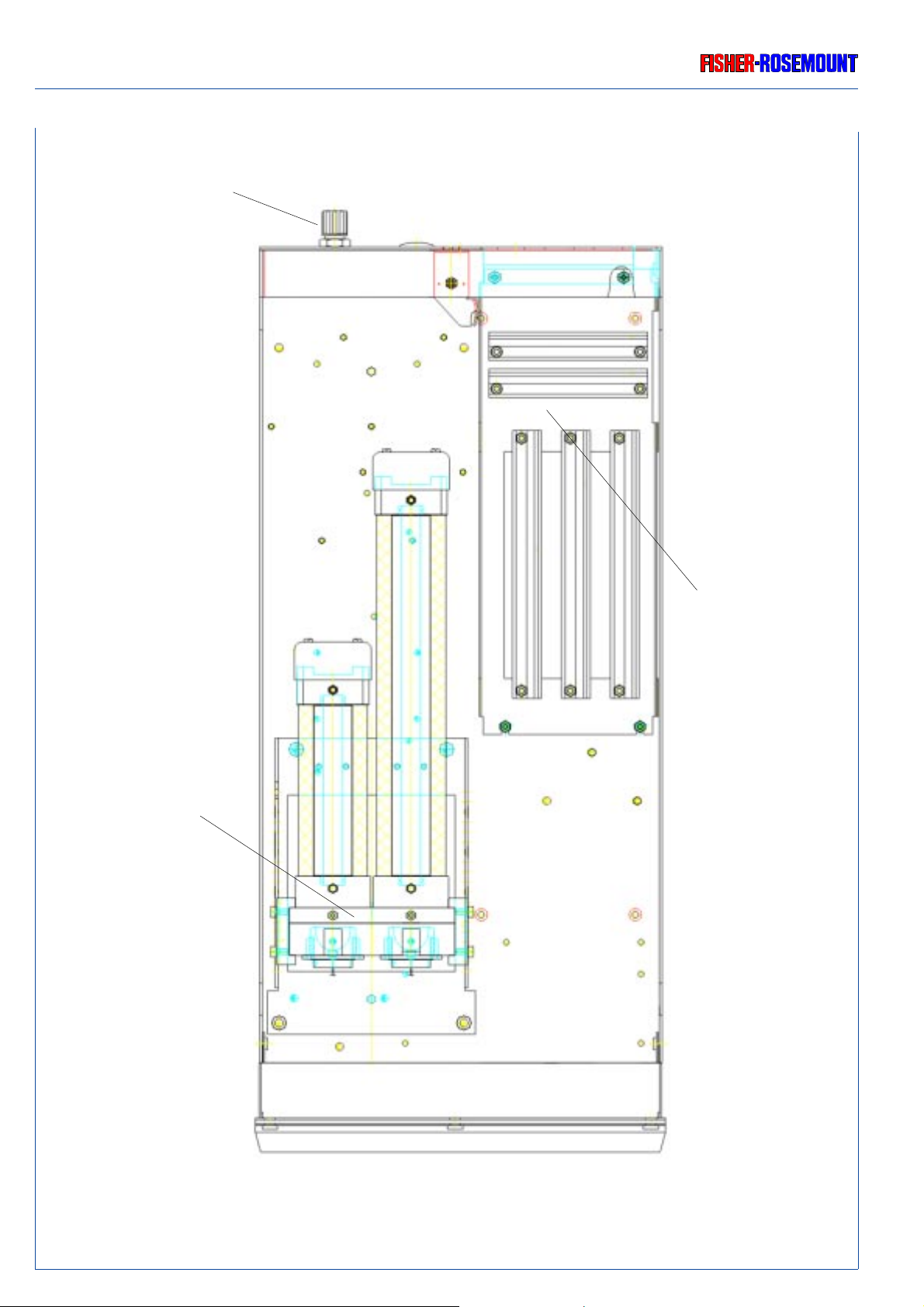
TECHNICAL DESCRIPTION
INTERNAL CONSTRUCTION
Gas Connections
Rosemount Analytical
Photometer Bench with
Pyroelectrical Detectors
(single or dual channel
assembly)
Card Cage
(see Item 1.3.2)
1 - 6
Fig. 1-6: BINOS E, 1/2 19" Analyzer Housing, Top view
(with 2 NDIR channels)
ETC00303(1) BINOS E e (2.0) 11/00
Page 23

Rosemount Analytical
TECHNICAL DESCRIPTION
INTERNAL GAS PATHS
1.3.1 Internal Gas Paths
The materials used for the gas paths may be selcted to suit the intendend application. In
marking such selection the diffusion rates of the individual gas components, their corrosivity,
and the temperature and pressure of the sampled gas must be taken into account.
a) Gas Path Material
The physical and chemical properties of the sample gas and the operating conditions
(temperature and pressure) of the analyzer determine the materials which may be used for gas
paths and gas fittings.
Fittings
For standard applications the analyzers are provided with PVDF fitting, 6/4 mm. The analyzers
can be shipped with swagelok® fittings, stainless steel, 6/4 mm or 1/4" as option.
Additional fittings to be delivered on request, consult factory.
Tubing
For standard applications the analyzers are provided with Viton or PTFE tubing (6/4 mm).
Stainless steel tubing is available for one or two gas p aths. Other configurations with ss tubing
may be provided on request. Special tubings may be on request af ter consulting factory.
Safety Filter
For standard applications the analyzers are provided with a safety filter (PTFE). This filter is no
substitute for a fine dust filter in the sample handling system.
ETC303(1) BINOS E e (2.0) 02/2007
1 - 7
Page 24
TECHNICAL DESCRIPTION
Rosemount Analytical
INTERNAL GAS PATHS
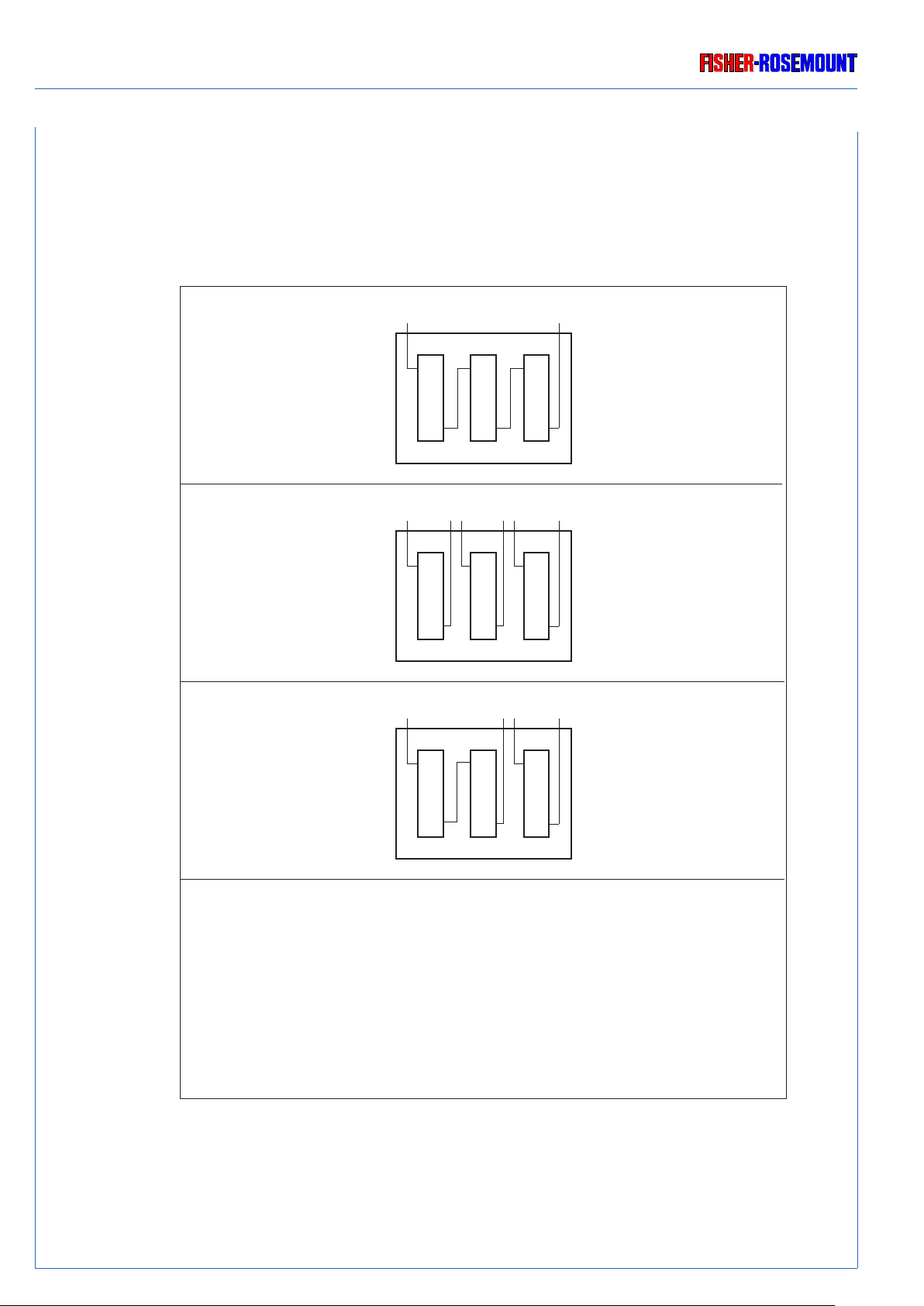
b) Gas Path Layout (internal tubing)
The principle various possible layouts of the internal gas lines are summarized in the table 1-
1.
OutIn
tubing in series
tubing in parallel
combined tubing:
series and parallel
(special tubing)
ULCO
special tubing:
external in series,
internal parallel
low
ultra
CO
OutOut In In
Out In
O
/H
CO
high
CO
OutIn
OutIn
OutIn
2
2
Note:
Tubing must not be
changed by customer
!
1 - 8
Table 1-1: Possible internal tubings (examples with 3 measuring channels)
ETC303(1) BINOS E e (2.0) 02/2007
Page 25
Rosemount Analytical
TECHNICAL DESCRIPTION
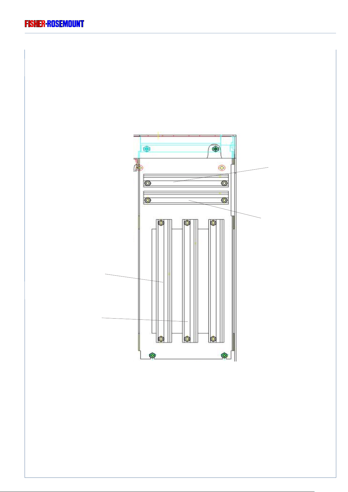
1.3.2 Printed Circuit Boards
All necessary PCBs are placed into a cardcage, which is identically for all BINOS E versions
(see Fig. 1-7).
BINOS E Rear Panel
Cardcage
LIO
(optional with 4 analog outputs
[optically isolated, common
ground] and RS 232 [optically
isolated] or CAN open bus
interface)
PCB
Physical Interface
(PIC*)
Signal Processing
(PSV*)
BINOS E Front Side
* For new models the combination PIC/PSV is replaced by a single DSP board.
Interconnection Board
(ICB)
ETC303(1) BINOS E e (2.0) 02/2007
Fig. 1-7: Card Cage BINOS E, Top View
1 - 9
Page 26

TECHNICAL DESCRIPTION
PCB
Rosemount Analytical
ICB
ICB is an interconnection board consisting of six 64-pin ICB bus slots to accommodate printed
circuit boards (PCB of Euro standard format).
LIO
The printed circuit board LIO offers the serial interface RS 232 and as an option 4 analog outluts
and an optically isolated serial interface or CAN open.
PSV/PIC Combination
*)
The PSV card (signal processing) carries out the A/D conversion and the real evaluation of
each measuring signal. This includes also all primary and all secondary variables: all
concentrations, temperatures, pressures and flow measurements. Any temperature and
pressure compensation is carried out from PSV . Linearization, zero and span calibration are
also executed in the PSV card.
The PIC card (Physics Interface Card) supplies the photometer components and the
individual sensors with the individual required operating voltages and transmits all measuring
signals to the signal processing unit PSV .
DSP (alternatively to PSV/PIC Combination)
*)
The DSP card (Digital Signal Processing) supplies the photometer components and the
individual sensors with the individual required operating voltages and carries out the A/D
conversion and the real evaluation of each measuring signal.
*) For new models the combination PIC/PSV is replaced by a single DSP board.
1 - 10
ETC303(1) BINOS E e (2.0) 02/2007
Page 27
Rosemount Analytical
TECHNICAL DESCRIPTION
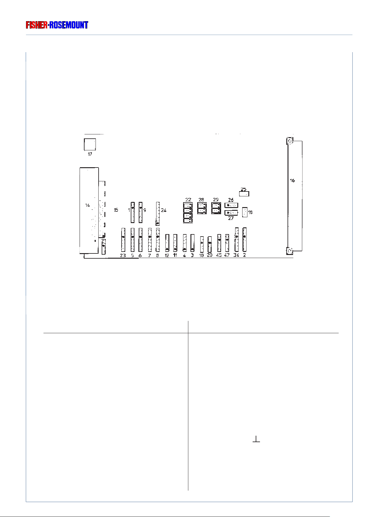
PIC
The PIC card (Physics Interface Card) supplies the photometer components and the individual
sensors with the individual required operating voltages and transmits all measuring signals to
the signal processing unit PSV.
PCB
1
2
3
Fig. 1-8: Plug pin assignment PCB PIC
The plugs shown in Fig. 1-20 are used as follows:
Plug No. used
34 Chopper 1 (channel 1+2)
2 Chopper 2 (channel 3+4)
47 Flow sensor 1
45 Flow sensor 2
20 Temperature sensor 1 (chopper 1)
10 Temperature sensor 2
3 Source channel 4
4 Source channel 3
11 Source channel 2
12 Source channel 1
8 Detector channel 4
7 Detector channel 3
6 Detector channel 2
5 Detector channel 1
23 Detector channel 5 (O
)
2
Plug No. used
1 Pressure senor 1
9 Pressure senor 2
24 PCB OKI (P2) Flow sensor 3
PCB OKI (P1) Flow sensor 4 (P1)
or
PCB OKI (P4) Temperature sensor 3
PCB OKI (P3) Temperature sensor 4
21.2 Proof peak (test peak) channel 1
21.3 Ground ( )
ETC303(1) BINOS E e (2.0) 02/2007
1 - 11
Page 28
TECHNICAL DESCRIPTION
Rosemount Analytical
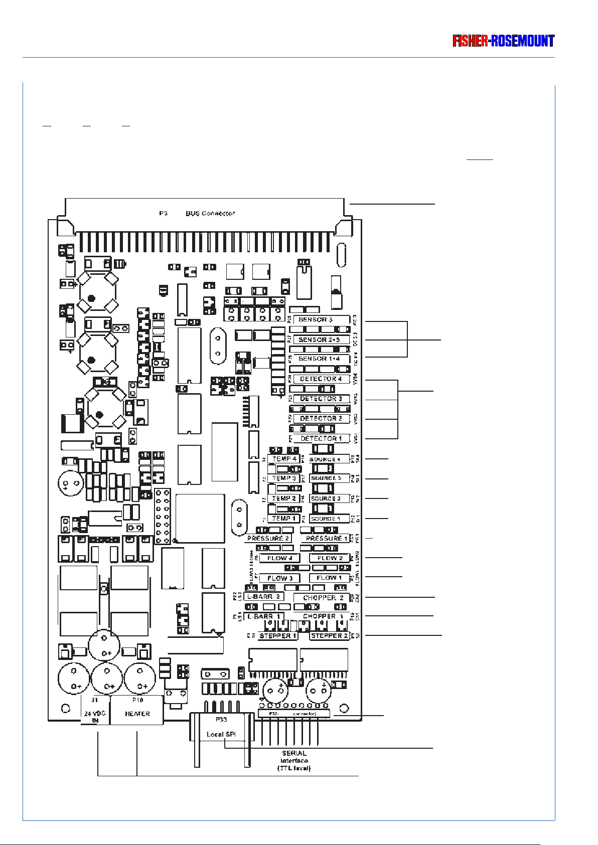
Digital Signal Processing Card (DSP)
Instead of using the 2 PCB's PIC and PSV alternatively those can be replaced by ONE board
containing both functions in the Digital Signal Processing Board DSP.
Bus connector
Input DC sensors
(e.g. O2/H2 sensors)
Input AC sensors
(e.g. IR/VIS/UV sensors)
Temp. sensor 4/IR(UV) source
Temp. sensor 3/IR(UV) source
Temp. sensor 2/IR(UV) source
Temp. sensor 1/IR(UV) source
Pressure sensor 2/Pressure sensor 1
Flow sensor 4/Flow sensor 2
Flow sensor 3/Flow sensor 1
not used/Chopper 2
not used/Chopper 1
4
3
2
1
1 - 12
not used/not used
Serial interface connector
Local SPI connector
24 VDC input/Heater connector
Fig. 1-9: Plug pin assignment PCB DSP
ETC303(1) BINOS E e (2.0) 02/2007
Page 29

Rosemount Analytical
MEASURING PRINCIPLE
IR MEASUREMENT
2. Measuring Principle
BINOS E can employ up to f our different measuring principles depending on the configuration
chosen. The methods are: NDIR, NDUV, paramagnetic and electrochemical Oxygen.
2.1 Non-dispersive Infrared (NDIR Measurement)
The non-dispersive infrared method is based on the principle of absorption of IR radiation by
the sample gas component being measured. The gas - specific wa velengths of the absorption
bands characterize the type of gas while the strength of the absorption gives a measure of the
concentration of the gas component being measured. An optical bench is in principle consisting
of an infrared light source, a chopper wheel to alternate the radiation intensity between the
reference and measurement (sample) side, an analysis cell, filter cells and a photometric
detector . Due to a rotation chopper wheel, the radiation intensities coming from measuring and
reference side of the analysis cell produce periodically changing signals within the detector.
The detector signal amplitude thus alternates between concentration dependent and concentration independent values. The difference between the two is a reliable measure of the
concentration of the absorbing gas component.
The principle photometer assembly is shown in Fig. 2-1.
Depending on the gas being measured, the application, the gas composition and the gas
concentration, one of two different measuring methods may be used as follows:
ETC00303(1) BINOS E e (2.0) 11/00
2 - 1
Page 30
MEASURING PRINCIPLE
IR MEASUREMENT
Rosemount Analytical
to electronic
14
12
11
10
14
13
11
10
99
8
7
8
7
5
3
1
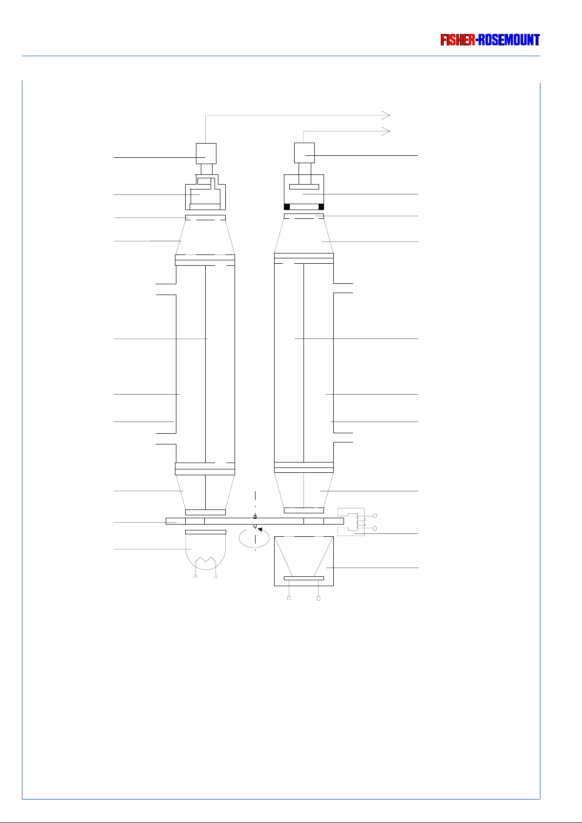
Fig. 2-1: Measuring Principle for NDIR / UV Measurement
1 IR source with reflector
2 VIS / UV source with reflector
3 Chopper wheel
4 Eddy current drive
5 Filter cell with dividing wall (IR channel)
6 Filter cell with dividing wall (UV channel)
7 Analysis cell
6
4
2
8 Measuring side
9 Reference side
10 Filter cell without dividing wall
(for IFC measurement with optical filters)
11 Window
12 Pneumatic or pyroelectrical (solid-state) detector
13 VIS / UV semiconductor detector
14 Preamplifier
2 - 2
ETC00303(1) BINOS E e (2.0) 11/00
Page 31

Rosemount Analytical
MEASURING PRINCIPLE
IR MEASUREMENT
2.1.1 Opto - Pneumatic Measuring Principle
In the opto-pneumatic method, a thermal radiator ( heating coil in the light source) generates
the infrared radiation (1) which passes through the chopper wheel (3).
Due to the special shape of the chopper wheel, the IR radiation passes through a filter cell (5)
and alternately reaches the measuring side (8) and reference side (9) of the analysis cell [(7)
separated in the middle into two halv es by an internal separating wall] with equal intensity.
The filter cell (5) screens interfering radiation areas out of the radiation spectrum.
After the analysis cell the radiation passes a second filter cell (10) and reaches the gas detector
(12), which compares the IR radiation intenisities from measuring side and reference side and
converts it into an AC voltage signal proportional to their respective intensity.
The opto-pneumatic detector (Fig. 2-2) consists of 2 gas-filled chambers, an absorption
chamber and a compensation chamber which are connected by a flow channel in which a
Microflow filament sensor is mounted.
In principle the detector is filled with the infrared active gas to be measured and is only sensitive
to this distinct gas with its characteristic absorption spectr um. The absorption chamber is
sealed with a window which are transparent for infrared radiation [usually CaF
(Calcium
2
fluoride), sometimes BaF2 (Barium fluoride)].
Absorption chamber
Flow channel with
Microflow sensor
CaF2 / BaF2 window
Gas intake connection
Compensation chamber
Fig. 2-2: Principle Design of the Opto-Pneumatic Gas Detector
ETC00303(1) BINOS E e (2.0) 11/00
2 - 3
Page 32

MEASURING PRINCIPLE
IR MEASUREMENT
Rosemount Analytical
When the IR radiation passes through the reference side of the analysis cell into the detector ,
no pre-absorption occurs. Thus, the gas inside the absorption chamber is heated, expands and
some of it passes through the flow channel into the compensation chamber.
When the IR radiation passes through the measurement side of the analysis cell into the
detector , a part of it is absorbed depending on gas concentration. The gas in the absorption
chamber, theref ore, is heated less than in the case of radiation coming from the reference side.
Now absorption chamber gas become colder, gas pressure in the absorption chamber is
reduced and some gas of compensation chamber passes through the flow channel into the
absorption chamber.
The flow channel geometry is designed in such a way that it hardly impedes the gas flow by
restriction. Due to the radiation of chopper wheel, the different radiation intensities lead to
periodically repeated flow pulses within the detector.
The Microflow sensor ev aluates these flow pulses and con verts them into electrical voltages.
The electronics, which follow, evaluate the signals and convert them into the corresponding
display and output format.
The high chopping rate used, permits using a portion of the perimeter of the chopper wheel
for responsivity recalibration. A special pattern of the chopper wheel illuminates the detector
with about 1/4 and then with about 3/4 of the total light intensity creating a so-called "proof
peak". Thus , with any chopper rotation, an automatic gain control is used f or automatic span
(sensitivity) control. The result is a high long-term stability of sensitivity.
2.1.2 Interference Filter Correlation (IFC Principle)
With the IFC method the analysis cell is alternately illuminated with filtered IR light concentrated in one of two spectrally separated wave length ranges. One of these two wavelength
bands is chosen to coincide with an absorption band of the sample gas and the other is chosen
such that none of the gas constituents expected to be encountered in practice absorbs
anywhere within the band.
The spectral transmittance curves of the interference filters used in the BINOS and the spectr al
absorption of the gases CO and CO
are shown in Fig. 2-3. It can be seen that the absorption
2
bands of these gases each coincide with the passbands of one of the interference filters.
2 - 4
ETC00303(1) BINOS E e (2.0) 11/00
Page 33

Rosemount Analytical
MEASURING PRINCIPLE
IR MEASUREMENT
9075604530150
Transmittance [%]
Transmittance [%]
CO
CO
HC
2
Reference
4400 460042004000 48003000 3200 3400 3600 3800 5000 5200 5400 5600 5800 6000
Wave Length [nm]
CO
2
CO
Interference
Filter
Absorption band
18 36 54 72 900
Fig. 2-3: Absorption Bands of Sample Gase Components and Transmittance of
Interference Filters
The interference filter, used for generating a reference signal, has its passband in a spectral
region where none of these gases absorb. Most of the other gases of interest also do not absorb
within the passband of this reference filter.
The photometer assembly is similar to the assembly with “gas detector” (Fig. 2-1) with the
exception of the analysis cell and the detector . The analysis cell is not devided into measuring
and reference side (selectivity by interference filters). After the analysis cell the radiation
passes a second filter cell (10) to reach the pyroelectrical (solid-state) detector (12).
The detector records the incoming IR radiation. This radiation will be reduced by the absorption
of the gas at the corresponding wav elengths. By comparing the intensities from the measuring
and reference wa velengths, an alternating voltage signal is produced. This signal results from
cooling and heating the pyroelectrical material.
ETC00303(1) BINOS E e (2.0) 11/00
2 - 5
Page 34

MEASURING PRINCIPLE
UV MEASUREMENT
Rosemount Analytical
2.2 UV Measurement
The absorption measurement in the UV spectral range is based on the same principle as the
IR measurement (Fig. 2-1).
A glow-discharge lamp [2] is used as radiation source.
The UV radiation passes through the chopper [3] and a filter cell [6] into the dual-section
analysis cell [7].
A second filter cell [6] is installed after the analysis cell. The photodetector [13], which follows,
converts the pulsating radiation intensities from measuring [8] and reference side [9] of the
analysis cell into electrical voltages.
As the glow-discharge lamp needs a specific and as constant as possible temperature , the UV
lamp is thermostat controlled to about 55 °C for BINOS E.
2 - 6
ETC00303(1) BINOS E e (2.0) 11/00
Page 35

Rosemount Analytical
2.3 Oxygen Measurement
Depending on analyzer model different two measuring methods will be used.
2.3.1 Paramagnetic Measurement
MEASURING PRINCIPLE
OXYGEN MEASUREMENT
The determination of O
concentration is based on the paramagnetic principle (magneto-
2
mechanic principle).
Two nitrogen-filled (N2 is diamagnetic) quartz spheres are arranged in a "dumbbell" configuration and suspended free to rotate on a thin platinum ribbon in a cell.
A small mirror that reflects a light beam coming from a light source to a photodetector, is
mounted on this ribbon. A strong permanent magnet especially shaped to produce a strong
highly inhomo-geneous magnetic field inside the analysis cell, is mounted outside the wall.
When oxygen molecules enter the cell, their paramagnetism will cause them to be drawn
towards the region of greatest magnetic field strength. The O2 molecules thus exert different
forces which produce a torque acting on the sphere arrangement, and the suspended
“dumbbell”, along with the mirror mounted on its suspension ribbon, will be angulary rotated
away from the equilibrium position.
The mirror then will deflect an incident light beam onto the photodetector which itself produces
an electric voltage. The electric signal is amplified and fed back to a conducting coil at the
“dumbbell”, forcing the suspended spheres back to the equilibrium position.
The current required to generate the restoring torque to return the “dumbbell” to its equilibrium
position is a direct measure of the O2 concentration in the gas mixture.
The complete analysis cell consists of analysis chamber, permanent magnet, processing
electronics, and a temperature sensor. BINOS E provides a thermostat controlled sensor at
approx. 55 °C. The temperature sensor is used to control the heating system.
ETC00303(1) BINOS E e (2.0) 11/00
2 - 7
Page 36

MEASURING PRINCIPLE
OXYGEN MEASUREMENT
Rosemount Analytical
2 - 8
Fig. 2-4: Principle Construction of paramagnetic Analysis Cell
1 Permanent magnet
2 Platinum wire
3 Mirror
4 Quartz spheres
5 Wire loop
6 Photodetector
7 Light source
8 Amplifier
9 Display
ETC00303(1) BINOS E e (2.0) 11/00
Page 37

Rosemount Analytical
MEASURING PRINCIPLE
OXYGEN MEASUREMENT
2.3.2 Electrochemical Measurement
The determination of O2 concentrations is based on the principle of a galvanic cell.
The principle structure of the oxygen sensor is shown in Fig. 2-5.
(Black)
Lead wire (Anode)
Lead wire (Cathode)
Anode
(Lead)
(1)
O ring (8)
Plastic disc (9)
Plastic top (10)
Cathode
Teflon membrane (4)
(Red)
Resistor (6)
Thermistor (5)
Acid electrolyte (3)
Sponge disc (7)
(Gold film)
(2)
Fig. 2-5: Structure of electrochemical Oxygen Sensor
The oxygen sensor incorporates a lead/gold oxygen cell with a lead anode (1) and a gold
cathode (2), using a specific acid electrolyte. To avoid moisture losses at the gold electrode a
sponge sheet is inserted on the purged side.
Oxygen molecules diffuse through a non-porous Teflon membrane (4) into the electrochemical
cell and are reduced at the gold-cathode. Water results from this reaction.
On the anode lead oxide is f ormed which is transfered into the electrolyte . The lead anode is
regenerated continuously and the electrode potential theref ore remains unchanged for a long
time.
The rate of diffusion and so the response time (t90) of the sensor is depending on the thickness
of the Teflon membrane.
ETC00303(1) BINOS E e (2.0) 11/00
2 - 9
Page 38

MEASURING PRINCIPLE
OXYGEN MEASUREMENT
Rosemount Analytical
(Red) (Black)
Thermistor (5)
(-)
Gold-
Cathode (2)
O2 + 4 H+ + 4 e- → 2 H2O
Summary reaktion O
(11)
Resistor (6)
2 Pb + 2 H2O → 2 PbO + 4 H+ + 4 e
Electrolyte (3)
(ph 6)
+ 2 Pb → 2 PbO
2
Fig. 2-6: Reaction of galvanic cell
(+)
Lead-
Anode (1)
-
The electric current between the electrodes is proportional to the O2 concentration in the gas
mixture to be measured. The signals are measured as terminal voltages of the resistor (6) and
the thermistor (5) for temperature compensation.
The change in output voltages (mV) of the sensor (11) represents the oxygen concentr ation.
Note !
Depending on measuring principle the electrochemical O
of oxygen (residual humidity av oids drying of the cell) . Supply cells continuously with dry sample gas
of low grade o xygen concentration or with o xygenfree sample gas could result a reversib le detuning
sensitivity. The output signal will become unstable.
of O
2
For correct measurement the cells hav e to be supplied with O
We recommend to use the cells in intervall measurement (purge cells with conditioned (dust removal
but no drying) ambient air during measurement breaks).
If it is necessary to interrupt oxygen supply f or several hours or da ys, the cell has to regenerate (supply
cell for about one day with ambient air). Temporary flushing with nitrogen (N2) for less than 1 h (e.g.
analyzer zeroing) will have no influence to measuring value.
cell needs a minimum internal consumption
2
concentrations of at least 0.1 Vol.-%.
2
2 - 10
ETC00303(1) BINOS E e (2.0) 11/00
Page 39

Rosemount Analytical
INSTALLATION AND PREPARATION OF STARTUP
5. Installation and Preparation of Startup
Please check the packing and its contents immediately upon arrival.
If any item is damaged or lost you are kindly requested to notify the f orwarder to undertake a
damage survey and report the loss or damage to us immediately.
If vibration decoupling is installed: Unscrew tr ansf er safety loc k of BINOS E !
Unscrew both knurled-head screws on bottom side of the housing
(Fig. 5-1a) ! For protection against loss screw the knurled-head screws into the
respective holders at housing rear side (Fig. 5-1b) !
Fig. 5-1a: Transfer safety lock
(housing side view, detail sketch)
Fig. 5-1b: BINOS E, Rear panel
Front panel
Transfer safety lock (two knurled-head screws)
(holder for safety lock)
ETC00303(1) BINOS E e (2.0) 11/00
5 - 1
Page 40

INSTALLATION AND PREPARATION OF STARTUP
INSTALLATION SITE
5.1 Installation Site
Be sure to observe the additional notes, safety precautions and w arnings given
in the individual manuals!
The BINOS E must not operate in e xplosive atmosphere without supplementary protective measures !
Free flow of air into and out of the BINOS E (ventilation slits) must not be
hindered by nearby objects or walls !
Rosemount Analytical
The installation site for the BINOS E has to be dry and remain above freezing
pointat all times. The BINOS E m ust be exposed neither to direct sunlight nor
to strong sources of heat.
Be sure to observe the permissible ambient temperatures (c.f. Item 20:
T echnical Data). F or outdoor installation, we recommend to install the BINOS
E in a protective cabinet. At least, the BINOS E has to be protected against rain
(e.g., shelter).
The BINOS E has to be installed as near as possible to the sample point, in order to avoid
low response time caused by long sample gas lines.
In order to decrease the response time, a sample gas pump with a matching high pumping rate
may be used. Eventually , the BINOS E has to be operated in the bypass mode or b y an overflow
valve to prevent too high flow and too high pressure (Fig. 5-2).
Exhaust
5 - 2
Overpressure valve
Gas sampling pump
BINOS E
Filter
Fig. 5-2: BINOS E, Bypass installation
Flow meter
Exhaust
ETC00303(1) BINOS E e (2.0) 11/00
Page 41

Rosemount Analytical
INSTALLATION AND PREPARATION OF STARTUP
GAS CONDITIONING (SAMPLE HANDLING)
5.2 Gas Conditioning (Sample Handling)
The conditioning of the sample gas is of greatest importance for the successful operation of
any analyzer according to extractive method.
All gases have to be supplied to the BINOS E as conditioned gases !
When the instrument is used with corrosive gases, it is to be verified that there
are no gas components which may damage the gas path components.
The gas has to fullfil the following conditions:
It must be
❏ free of condensable constituents
❏ free of dust
❏ free of aggressive constituents which are not compatible with the material of the gas
paths.
❏ have temperatures and pressures which are within the specifications shown in “T echnical
Data” of this manual.
Flammable or (potential) explosive gas mixtures may not be introduced into
the BINOS E without supplementary protective measures !
When analysing vapours, the de wpoint of the sample gas has to be at least 10 °C belo w the
ambient temperature in order to avoid the precipitation of condensate in the gas paths.
Suitable gas conditionning hardware ma y be supplied or recommended for specific analytical
problems and operating conditions.
ETC00303(1) BINOS E e (2.0) 11/00
5 - 3
Page 42

INSTALLATION AND PREPARATION OF STARTUP
GAS CONDITIONING (SAMPLE HANDLING)
Rosemount Analytical
5.2.1 Pressure Sensor (Option)
It is possible to integrate up to two pressure sensors with a range of 800 - 1100 hPa.
The concentration values computed by the analyzer will then be corrected to reflect the
barometric pressure to eliminate faulty measurements due to changes in barometric pressure
(see technical data). BI NOS E front panel progr am will indicate whether pressure correction
is actual.
5.2.2 Gas Flow Rate / Internal Flow Sensor (Option)
The gas flow rate should be within the range 0.2 l/min to maxi. 1.5 l/min !
A constant flow rate of about 1 l/min is recommended.
The gas flow rate for BINOS E with paramagnetic oxygen sensor
is allowed to max. 1.0 l/min !
Internal flow sensor: max. 2.0 l/min !
It is possible to integrate up to three flow sensors. In this case gas flow can be shown via
BINOS E front panel program.
5.3 Gas Connections
The installed gas connections are specific to the different BINOS E. All fittings are clearly
marked. The fittings are located on the rear panel of the BINOS E instrument.
5 - 4
The exhaust gas lines have to be mounted in a declining, pressureless
and frost-free way and according to the valid emission legislation !
Do not interchange gas inlets and gas outlets !
ETC00303(1) BINOS E e (2.0) 11/00
Page 43

Rosemount Analytical
INSTALLATION AND PREPARATION OF STARTUP
GAS CONNECTIONS
5.3.1 Standard
Depending on BINOS E version the following gas connections are installed:
in = Gas inlet out = Gas outlet
Channel 1 = measuring channel 1 Channel 2 = measuring channel 2
Channel 3 = measuring channel 3 reference = Reference gas (Differential measurement)
purge = purge gas (housing)
Zero gas and span gas are introduced directly via the sample gas inlet. The test gas containers
have to be set up according to the current legislation.
Be sure to observe the safety regulations for the respective gases
(sample gas and test gases / span gases) and the gas bottles !
ETC00303(1) BINOS E e (2.0) 11/00
Fig. 5-3: BINOS E, standard gas connections
5 - 5
Page 44

INSTALLATION AND PREPARATION OF STARTUP
Rosemount Analytical
5 - 6
ETC00303(1) BINOS E e (2.0) 11/00
Page 45

Rosemount Analytical
STARTUP PROCEDURE (SWITCHING
6. Startup Procedure (Switching On)
Be sure to observe the safety precautions and warnings !
Be sure to observe the additional notes, safety precautions and w arnings given
in the individual manuals !
Once the instrument has been correctly assembled and installed in accordance with the
general instructions given in section 5., the equipment is ready for operation.
ON)
The equipment is switched on b y providing the required voltage.
Upon switching on, the analyzer will perform a self-diagnostic test routine.
The BINOS E front panel program should be installed bef ore connecting the BINOS E to the
designated COM port.
The following devices are recommended to connect BINOS E with the PC:
- Zero modem cable (part number: ETC00257)
- Gender changer (part number: ETC00258)
For additional informations about recommended hardware and software requirements, see
chapter "Front Panel Program".
Analyzer needs 15 to 50 minutes to warm-up after switch on,
depending on the installed detectors (themostat controlled temperature) !
ETC00303(1) BINOS E e (2.0) 11/00
6 - 1
Page 46

STARTUP PROCEDURE (SWITCHING ON)
SUPPLY VOLTAGE
Rosemount Analytical
6.1 Supply Voltage
The BINOS E is specified for an operating voltage of 24 V DC (± 5 %).
24 Vdc is to be connected via a 3-pole XLR flange (male).
The dc supply voltage is to be provided b y option UPS 01 T, SL5, SL10 or equivalent power
supply.
❍ Connect power supply and BINOS E (Fig. 6-1, Plug 24 V DC).
Verify correct polarity before operation (Fig. 21-1) !
❍ Connect mains line and power supply.
Be sure to observe the safety precautions and warnings given by
manufacturer of power supply !
Pin assignments
Plug 24 V dc
6 - 2
Fig. 6-1: BINOS E, Rear panel, Voltage supply
ETC00303(1) BINOS E e (2.0) 11/00
Page 47

Rosemount Analytical
MEASUREMENT/CALIBRATION/SWITCHING (SHUT) OFF
MEASUREMENT
7. Measurement / Calibration / Switching (Shut) Off
7.1 Measurement
The primary step in the measurement of the concentration of a gas component is the admission
of sample gas to the analyzer.
Analyzer needs 15 to 50 minutes to warm-up after switch on,
depending on the installed detectors (thermostat controlled temperature) !
❍ Admit sample gas at the respective gas inlet fitting (see Item 5.).
❍ Set the gas flow rate to allowable rate.
Before starting an analysis, however, the following should be performed:
❏ BINOS E front panel program should be installed and BINOS E should be connected to
the designated COM port. Initialization from connected analyzer or from configuration file
should have been carried out.
❏ Zero and span gas calibration of the BINOS E (see chapter 8).
Note for analyzers with electrochemical O2 cell!
Depending on measuring principle the electrochemical O
of oxygen (residual humidity av oids drying of the cell). Supply cells continuously with dry sample gas
of low grade o xygen concentr ation or with oxygenfree sample gas could result a reversib le detuning
of O
sensitivity. The output signal will become unstable.
2
For correct measurement the cells have to be supplied with O
We recommend to use the cells in intervall measurement (purge cells with conditioned (dust remov al
but no drying) ambient air during measurement breaks).
If it is necessary to interrupt oxygen supply for sev eral hours or days, the cell has to regenerate (supply
cell for about one day with ambient air). Temporary flushing with nitrogen (N2) for less than 1 h (e.g.
analyzer zeroing) will have no influence to measuring value.
cell needs a minimum internal consumption
2
concentrations of at least 0.1 Vol.-%.
2
90002929(6) NGA-MLT e 30.10.99
7 - 1
Page 48

MEASUREMENT/CALIBRATION//SWITCHING (SHUT) OFF
CALIBRATION
Rosemount Analytical
7.2 Calibration
To insure correct measurement results, zeroing and spanning should be carried out once a
week.
The zero level must always first be set before any other calibrations are attempted.
For the calibration procedure the required test gases have to be fed to the analyzer through
the respective gas inlets (cf . section 5.3) with a no - back - pressure gas flow rate of about 1
l/min (the same as with sample gas) !
7.2.1 Calibration (Test) Gases
a) Zero Gas
For zeroing, the analyz er has to be purged with nitrogen (N
) or adequate zero gas [e. g. synth.
2
air or conditioned air (not as a standard for O2 measurement)].
.
b) Span Gas
The calibration of all another analyzers should be done with pure span gases in order to prev ent
interferences between the gases (e. g., CO2 and CO) measured by the analyzer. Test gas
mixtures are also possible depending on the mixed components (c.f. or test gas supplier).
The concentration range of the span gas has to be in a range of 80 - 110 % of the full scale
range of the respective measuring channel. For low er span gas concentrations the measuring
accuracy could be lower for sample gas concentrations, which are higher than the span gas
concentration! For test gas concentration see certification of the test gas bottles.
Spanning for o xygen measurement can be done using conditioned ambient air as span gas ,
if the oxygen concentration is known and constant.
To calibrate a H2O channel (0 - 3(4) Vol.-%), use water vapor saturated N2 according to
saturation characteristic (Item 22.) as span gas. Purge N2 through a gas-blubber bottle, filled
with distilled water and in a little bit higher ambient temperature as necessary. Connect a
second vessel into a kyrostat (to hold ambient temperature constant) in series to get defined
dew point.
7 - 2
90002929(6) NGA-MLT e 30.10.99
Page 49

Rosemount Analytical
MEASUREMENT/CALIBRATION/SWITCHING (SHUT) OFF
SWITCHING (SHUT) OFF
Be sure to observe the safety regulations for the respective gases
(sample gas and test gases / span gases) and the gas bottles !
Pressure of sample gas / test gases normally max. 1,500 hPa !
7.3 Switching (Shut) Off
Before switching off the analyzer, we recommend first purging all the gas lines for about 5
minutes with zeroing gas (N2) or adequate conditioned air . The full procedure for shutting off
is as follows:
All analyzers with electrochemical O2 cell have to be purged with conditioned
ambient air prior to disconnect the gas lines !
Then the gas line fittings have to be closed f or transport or depositing analyzer.
❍ Admit zeroing gas at the respective gas inlet fitting.
❍ Set the gas flow to permissible rate.
After 5 minutes have elapsed:
❍ Switch off by disconnecting the voltage supply.
❍ Shut Off the gas supply.
❍ Disconnect gas lines.
❍ Close all gas line fittings immediately.
90002929(6) NGA-MLT e 30.10.99
7 - 3
Page 50

MEASUREMENT/CALIBRATION//SWITCHING (SHUT) OFF
Rosemount Analytical
7 - 4
90002929(6) NGA-MLT e 30.10.99
Page 51

Rosemount Analytical
FRONT PANEL PROGRAM
8. BINOS E Front Panel Program
The description of the BINOS E Front Panel Program includes the following information:
1. Requirements
2. Installation and Startup
3. Function Keys
4. Status Display
5. Display Page
6. Recorder Page
7. Messages Page
8. Analog Output Link and Adjustment Page
REQUIREMENTS
8.1 Requirements
Listed below are the minimum recommended hardware and software requirements for installing the BINOS E front panel program in a Microsoft Windows 95, 98 or NT operating
system:
· Pentium processor with 233 MHz or better
· 32 MB RAM (higher RAM improves performance)
· Sufficient available hard disk space. The required available space depends on the
data acquisition rate (see chapter 5) (Calculate approx. 63 MB per day if the fastest
data acquisition is running without data compression).
· 8 MB graphic board
· Serial interface (RS 232 COM port)
The following devices are recommended to connect the BINOS E with your PC:
· Zero modem cable (part number: ETC00257)
· Gender changer (part number: ETC00258)
These accessories can be provided by Fisher-Rosemount with the BINOS E analyzer as
options.
ETC00303(1) BINOS E e (2.0) 11/00
8 - 1
Page 52

FRONT PANEL PROGRAM
INSTALLATION
Rosemount Analytical
8.2 Installation and Startup
8.2.1 Installation
Start Setup.exe for the BINOS E front panel program installation and follow the program
instructions.
The following operations must be activated:
a) Desired language
b) Designated COM port
8 - 2
ETC00303(1) BINOS E e (2.0) 11/00
Page 53

Rosemount Analytical
The program will then create the following directory:
C:\ Programs\ Fisher-Rosemount\ BINOS E.
FRONT PANEL PROGRAM
INSTALLATION
The following files are available in the installation listing:
Ascii.dad (after first measurement), Binos.exe, Binos.eni, BinosOEM.INI, BinosCustom.OEM
(after first start, see chapter 8.2), ConfigOEM.INI, daten.ddd, daten.ddt, Default.OEM,
README.txt, Install.log, Unwise.exe, Unwise.ini as well as a listing ”Data”.
After successful installation, a corresponding program group will be generated
and the BINOS E program is ready to start.
ETC00303(1) BINOS E e (2.0) 11/00
8 - 3
Page 54

FRONT PANEL PROGRAM
STARTUP
Rosemount Analytical
8.2.2 Startup
The first time the BINOS E program is started, a dialog box will inform you that the configuration data is loaded. This procedure may take several seconds.
Based on this data, a standard file ”BinosCustom.OEM” will be created. This file will be loaded
automatically on any future start to initialize the BINOS E front panel.
Any front panel page (Display, recorder , messages or analog out) offers a headline showing the following information about the specific instrument:
· BINOS E software version (Release Number)
· Adjusted COM port
· BINOS E serial number (important for service and maintenance)
8.3 Function Keys
The function keys F1 through F12 are located on the upper right side of any front panel page:
F1 Display:
The ”Display” function key enables you to reach the display page
of this program (see chapter 8.5) .
F2 Recorder:
The ”Recorder” function key enables you to reach the recorder
page of this program (see chapter 8.6).
F3 Messages:
The ”Messages” function key enables you to reach the messages
page of this program (see chapter 8.7).
F4 Analog out.:
The ”Analog out.” function key (Analog Output Link and Adjustment Page) allows you to link and adjust measuring channels or
secondary parameters to the analog outputs and change the settings (see chapter 8.8).
8 - 4
ETC00303(1) BINOS E e (2.0) 11/00
Page 55

Rosemount Analytical
F5 Zero Gas Calib.:
The ”Zero gas calib.” function k ey starts the dialog for zero gas calibration.
A TTENTION: Before starting zero gas adjustment make certain that zero gas is
available!
FRONT PANEL PROGRAM
FUNCTION KEYS
The dialog allows you to select single channels for calibration or to calibrate all channels
simultaneously.
ETC00303(1) BINOS E e (2.0) 11/00
8 - 5
Page 56

FRONT PANEL PROGRAM
FUNCTION KEYS
Rosemount Analytical
During zero gas adjustment the deviation of the actual value is compared with the max.
deviation (threshold value) from the file ”BinosOEM.INI”.
The menu provides the ability to change the
threshold value from 1 % of full scale up to the
maximum threshold value.
If the threshold value is exceeded, an alarm message will appear offering the option to stop the
zero gas calibration procedure.
F6 Span gas calib.:
The ”Span gas calib.” function k ey starts the dialog for span gas calibration.
ATTENTION: Bef ore starting span gas adjustment, ensure that span gas with
the desired concentration is available!
To protect this function against unauthorized access, a password (access code)
option is available.
If no password has been set you will be
asked to define one (this is not required).
Within this dialog box you can also
change the existing access code.
If a password is defined, it can be
changed but not eliminated entirely.
8 - 6
ETC00303(1) BINOS E e (2.0) 11/00
Page 57

Rosemount Analytical
FRONT PANEL PROGRAM
FUNCTION KEYS
As with zero gas adjustment, you can run span
gas calibration with individual selectable channels or with all channels
simultaneously.
Unavailable channels will
be refused.
You can set the nominal
value (set point) in the field
behind the corresponding
channel.
During span gas adjustment, the deviation of the actual value is compared with the max.
deviation (threshold v alue) from the file ”BinosOEM.INI”. The menu provides the opportunity to
change the threshold value from 1 % of full scale up to the maximum threshold value.
ETC00303(1) BINOS E e (2.0) 11/00
If the value falls below the threshold
value, the span gas calibration procedure is stopped.
To enable a span gas calibration, the
maximum threshold value may be set
(if this does not work contact our Service Support Center).
8 - 7
Page 58

FRONT PANEL PROGRAM
FUNCTION KEYS
Rosemount Analytical
If any dialog or communication does not work correctly you will get a message indicating
the wrong input.
If for example no channel is selected for zero calibration the following message will show
up:
F7 Start measure.:
The "Start measure." function key initiates the measuring procedure. After any successful
startup the measurement itself needs to be started. Otherwise you see a display being not
illuminated.
F8 Stop measure.:
The ”Stop measure.” function key terminates the measuring procedure. Please wait appro ximately 30 seconds before any ne w start.
F9 Raw/Measure:
The ”Raw/Measure” function key enables the user to switch from raw data mode [not corrected
(unlinearized, not temperature compensated) data] to measurement mode [concentrations].
This procedure may take several seconds.
8 - 8
ETC00303(1) BINOS E e (2.0) 11/00
Page 59

Rosemount Analytical
F10 Initialization:
FRONT PANEL PROGRAM
FUNCTION KEYS
The ”Initialization” function
key enables two different
methods for initialization leading to the dialog box ”device
data”:
If you select in the dialog box ”read device data” the option ”from connected analyzer” the data
will be loaded directly from the connected BINOS E instrument.
If you select the option ”from configuration file” within this dialog box, the corresponding
configuration file will be selected and loaded.
ATTENTION:
The file ”BinosCustom.OEM” initially created will not be changed in that
case! At the next program start with the option ”from connected analyzer”
the original status will be restored.
F12 Quit:
ETC00303(1) BINOS E e (2.0) 11/00
The ”Quit” function key
ends the program with ”Exit
BINOS E program”.
8 - 9
Page 60

FRONT PANEL PROGRAM
STATUS DISPLAY
Rosemount Analytical
8.4 Status Display (”Status”)
The status display on the lower right side of any front panel page shows the actual state of the
program:
LED ”Data”: This LED flashes when the BINOS E data is available.
LED ”Raw data”: This LED is illuminated if the analyzer is working in raw
data mode.
LED ”Non-lin. Mode”: This LED is illuminated during the instrument
mode ”not linearized”.
LED ”Meas. active”: This LED is illuminated during measurement.
LED ”Load”: This LED is illuminated when configuration data from a
connected BINOS E or a file is loaded.
LED ”Reset”:This LED is illuminated if the software is reset at the
instrument. This happens after each initialization.
8 - 10
ETC00303(1) BINOS E e (2.0) 11/00
Page 61

Rosemount Analytical
FRONT PANEL PROGRAM
DISPLAY PAGE
8.5 Display Page
The ”Display page” [F1 Display] shows all the connected channels and the accompanying data
for the respective gas.
The LED’s under the category ”Information”
indicate the selected configurations and options for each channel. If the LED ”Message” is
illuminated, a failure message for the respective channel is available on the messages
page.The measuring gas and the corresponding smallest and highest ranges are indicated.
A maximum of five channels can be displayed. Active channels are illuminated.
The ”smoothing” that allows the t90 time to be adjusted to
strong, weak or medium. Selection is activated by clicking
the RIGHT MOUSE BUTT ON.
ETC00303(1) BINOS E e (2.0) 11/00
8 - 11
Page 62

FRONT PANEL PROGRAM
DISPLAY PAGE
Rosemount Analytical
Secondary Parameters:
The option to show five more secondary parameters
(signal sources) such as temperature, flow or pressure
on an extra panel is available.
To select the source, the user must click the RIGHT
MOUSE BUTTON on the title strip of the panel and
then select the respective source from the menu.
If a sensor is not available the following signals are
displayed:
Temperature: - 273 °C
Flow: 0 ml/min [cc/min]
Pressure: 2000 hP a [mbar]
The free selectable sensor can be Temperature, Flow
or Pressure indicated by the unit (flow = ml/min).
Decimal Places:
The decimal places for
the measuring gas
concentrations can be
adjusted respectively
to the ranges.
To adjust the decimal places, click the RIGHT MOUSE BUTT ON on the corresponding digital
display . If the concentration is indicated in V olume percent (V ol.-%), a maximum of five decimal
places can be selected; in the case of ppm, a maximum of three decimal places can be
selected.
8 - 12
ETC00303(1) BINOS E e (2.0) 11/00
Page 63

Rosemount Analytical
FRONT PANEL PROGRAM
DISPLAY PAGE
Additional Data Source:
An additional data source may be adjusted at the bottom of this display page (”Signal
selection”).
Signal selection can be done with the mouse in the same manner as noted above (RIGHT
MOUSE BUTT ON).
ETC00303(1) BINOS E e (2.0) 11/00
8 - 13
Page 64

FRONT PANEL PROGRAM
RECORDER PAGE
Rosemount Analytical
8.6 Recorder Page
For all active channels, a recorder channel is available [F2 Recorder]. Up to five channels can
be shown.
For each channel, the recorder adjustments can be set individually. In this case , a dialog box
appears after touching the respective button (Recorder 1, 2, 3 ...). Options to adjust the scale
individually (manually), to reproduce the factory settings (default values) or to view the actual
scale of the recorder (Auto range) are also available.
The decimal places of the scale may be configured here as well.
8 - 14
ETC00303(1) BINOS E e (2.0) 11/00
Page 65

Rosemount Analytical
8.6.1 Averaging:
FRONT PANEL PROGRAM
RECORDER PAGE
Using a rotary regulator and a selectable multiplier (1x, 10x, 100x) an average can be calculated for data compression. To calculate the
average, the respective multiplier and the desired value at the rotary regulator must be adjusted. The data will then be averaged.
During the measurement no change of averaging is possible!
8.6.2 Spooling:
8.6.3 Recording:
Four spool buttons are available so the user can spool
forward, backwards, to the beginning and to the end of
the recorded text.
The recorded data may be stored in
two formats:
a) As ASCII file
b) As recorder file
ETC00303(1) BINOS E e (2.0) 11/00
The recorder file can later be loaded
into the recorder again.
Using the ”Load” and ”Close” options,
any available file can be loaded or
closed again.
8 - 15
Page 66

FRONT PANEL PROGRAM
MESSAGES PAGE
Rosemount Analytical
8.7. Messages Page
On the Messages page [F3 Messages] the status of the program and the connected BINOS E
instrument is shown.
Events:
On the upper left side an error report (failures, messages) is recorded which also indicates the
time and date.
Zero or span gas calibration
reports are shown reporting
the adjusted channels. The
failure (sum error) of a channel (signal) will be indicated
as ”unlock” while ”locked”
appears when the failure
disappears.
8 - 16
ETC00303(1) BINOS E e (2.0) 11/00
Page 67

Rosemount Analytical
FRONT PANEL PROGRAM
MESSAGES PAGE
Below this area a failure of the serial interface is shown via LED (illuminated in case or error).
After that you can start the error report again with ”read status/messages again”. You can store the error
reports into the directory ”Data” with
”save messages” before activating a
new error report.
Detailed information to the failure messages are indicated
under the category ”Messages” in the lower area of this
page. For each connected channel failure messages – split
up in six areas - are indicated. In case of any failure the
corresponding LED is illuminated.
In the expert level (Service has access) differentiated messages are available. Special
messages for the Service are shown in the lowest part of this area (consult our Service Support
Center).
ETC00303(1) BINOS E e (2.0) 11/00
On the upper right side of this page, under ”Status”, is
the hardware configuration of the BINOS E instrument
showing the presence of the 6 defined or the 2 pairs of
selectable optional sensors (signal sources). The a vailability of 1-2 temperature and 1-2 pressure sensors is
indicated via LED (not possible for the 2 flow sensors).
The display will also indicate whether the additional
selectable pairs of sensors are temperature or flow
sensors.
Beside this is information about the AD changers or
transmission rates.
8 - 17
Page 68

FRONT PANEL PROGRAM
ANALOG OUTPUT LINK AND ADJUSTMENT PAGE
Rosemount Analytical
8.7. Analog Output Link and Adjustment Page
On the ”Analog Output Link and Adjustment Page” [F4 Analog out.] the four optional analog
outputs of a BINOS E analyzer can be linked to the respective channels or secondary
parameters (sensors).
To view the actual settings, press the button
”read analog link” (LED ”reading active” is
illuminated).
ATTENTION: Stop Measurement with F8 before adjustments can be perf ormed!
Now new channel adjustments (concentration measurements) can be performed. Beside
concentrations also secondary signal sources (temperature, pressure or flow) can be selected.
Any ”begin of range” or ”end of range” can be set individually. The corresponding units are
assigned automatically.
8 - 18
ETC00303(1) BINOS E e (2.0) 11/00
Page 69

Rosemount Analytical
FRONT PANEL PROGRAM
ANALOG OUTPUT LINK AND ADJUSTMENT PAGE
A TTENTION: Please remember that beside any customer settings, the specifications are valid only if the end of range is fixed between the ordered minimum and
maximum end of range. Suppressed ranges (increased begin of range) must be
indicated in the purchase order as well.
The default settings from
factory may not go conform
with the secondary sensor
properties. Please adjust
according to your needs.
To store the changed adjustments the button ”write analog link” has to be activated
(LED ”writing active” is illuminated).
ETC00303(1) BINOS E e (2.0) 11/00
8 - 19
Page 70

FRONT PANEL PROGRAM
Rosemount Analytical
8 - 20
ETC00303(1) BINOS E e (2.0) 11/00
Page 71

Rosemount Analytical
BINOS E DATA EXCHANGE
9. BINOS E Data Exchange
BINOS E analyzer is equipped with a serial interface enabling communication with a host
computer.
Alternatively to the BINOS E Front P anel Program user may create their own programs refering
to the BINOS E data exchange via RS 232 interface.
The Digital Signal Processor (DSP) is sending periodically a data block (30 ms multiplicated
with the adjusted avar age time). The host computer can send commands to the DSP during
reading to prescribe or alter parameters as well as initiate analyzer operations, using a
standardized protocol.
The parameters for data exchange and the syntax of the telegrams to be established in
protocols are available on request - consult factory.
ETC00303(1) BINOS E e (2.0) 11/00
9 - 1
Page 72

BINOS E DATA EXCHANGE
Rosemount Analytical
9 - 2
ETC00303(1) BINOS E e (2.0) 11/00
Page 73

Rosemount Analytical
MAINTENANCE
13. Maintenance
In general only the gas conditionning hardware (sample handling system) will require
maintenance.
The analyzer itself requires very little maintenance.
The following checks are recommended for maintenance of the proper operation of the
analyzer.
Check and adjust zero level: weekly
(low concentrations: daily)
Check and adjust span: weekly
Perform leak testing: 6 times annually.
The maintenance frequencies stated above are presented as guidelines only; maintenance
operations may be required more or less frequently , depending upon usage and site conditions.
ETC00303(1) BINOS E e (2.0) 11/00
13 - 1
Page 74

MAINTENANCE
Rosemount Analytical
13 - 2
ETC00303(1) BINOS E e (2.0) 11/00
Page 75

Rosemount Analytical
LEAK TESTING
14. Leak T esting
Testing for gas leakage should be performed at bimonthly intervals and always immediately
after any repair or replacement of gas - line components is performed. The test procedure is
as follows:
Analyzer /
Analyzer Module
Overpressure
Valve
Water
Fig. 14-1: Leak Testing with an U - Tube - Manometer
approx. 50 hPa
❍ Install a water - filled U - tube manometer at the sample gas outlet;
❍ Install a shut-off valve at the sample gas inlet.
Admit air into the instrument at the shut-off valve until the entire analyzer is subjected
to an overpressure of 50 hPa (approximately 500 mm water column; see Fig. 14-1).
Close the shut-off valve and verify that following a brief period required for pressure equilibrium,
that the height of the water column does not drop over a period of about 5 minutes.
Any external devices, such as sample gas cooling hardware, dust filters etc., should be
checked in the course of leak testing.
Overpressure max. 500 hPa !
For differential measurement the leakage check must be performed for
measurement side and reference side separately !
For analyzers with par allel gas paths the leakage check must be performed for
each gas path separately !
ETC00303(1) BINOS E e (2.0) 11/00
14 - 1
Page 76

LEAK TESTING
Rosemount Analytical
14 - 2
ETC00303(1) BINOS E e (2.0) 11/00
Page 77

Rosemount Analytical
OPENING OF HOUSING
15. Opening the Housing
The housing must be opened for checking the electrical connections and for replacement or
cleaning of any of the components of the analyzer.
Be sure to observe Item 6. of the safety measures !
15.1 BINOS E (Sheet-metal housing)
15.1.1 Housing Cover
❍ Disconnect all voltage supplies.
❍ Unscrew the respective fastening screws at both housing sides (Fig. 15-1).
❍ For rear cov er unscrew the additonal f astening scre w at the top of the housing (Fig. 15-1)
❍ Remove the respective housing top cover panel.
Closing of the housing is performed in reverse order.
Top fastening screws,
rear housing cover
Fastening screw,
rear housing cover
ETC00303(1) BINOS E e (2.0) 11/00
Fastening screw,
front housing cover
Fig. 15-1: BINOS E, Metal-sheet housing
(Fastening screws housing cover)
15 - 1
Page 78

OPENING OF HOUSING
Rosemount Analytical
15.2 BINOS E (1/2 19" housing)
15.2.1 Housing Cover
❍ Disconnect all voltage supplies.
❍ Unscrew fastening screws for rack-mounting / front frame if necessary (Fig. 1-1).
Remove analyz er out of rack or remove the front mounting frame and carrying strap to
rear.
❍ Unscrew the respective fastening screws at both housing sides (Fig. 15-2)
❍ Remove the respective housing top cover panel.
Closing of the housing is performed in reverse order.
fastening screws housing cover
Fig. 15-2: BINOS E (1/2 19" housing)
(Fastening screws housing cover)
15 - 2
ETC00303(1) BINOS E e (2.0) 11/00
Page 79

Rosemount Analytical
REPLACEMENT AND CLEANING OF PHOTOMETRIC COMPONENTS
REMOVAL OF THE PHOTOMETER ASSEMBLY
17. Replacement and Cleaning of Photometric Components
The housing has to be opened for checking the electrical connections and for replacement or
cleaning of any of the components of the equipment.
Be sure to observe the safety measures, Item 5. and 6. especially !
17.1 Removal of the Photometer Assembly
Open the housing (cf. Section 15).
Disconnect all electrical connections between photometer assembly and electronic unit
(pcb PIC or DSP) and remove all gas lines from the photometer assembly if necessary .
Unscrew both the hexagonal screws shown in Fig. 17-1.
Depending on photometer or analyzer/analyzer module there could be exist hot
components !
Remove the photometer assembly to top of analyzer housing as a unit.
hexagonal screw
ETC00303(1) BINOS E e (2.0) 02/2007
hexagonal screw
Fig. 17-1: Photometer Assembly, example
(Top view, detail)
17 - 1
Page 80

REPLACEMENT AND CLEANING OF PHOTOMETRIC COMPONENTS
LIGHT SOURCE REPLACEMENT
Rosemount Analytical
17.2 Light Source Replacement (IR)
Open the housing (cf. Section 15).
Remove the photometer assembly out of analyzer housing (see Section 17.1).
Remove the two light source hexagonal mounting screws (shown in Fig. 17-2 as Item 1).
Remove the light source together with its mounting flange.
Remove the mounting flange from the light source and position it on the new light source.
Insert the new light source and flange in the same position as the old one.
Insert and tighten the two light source hexagonal mounting screws (Fig. 17-2).
Then:
Replace the photometer assembly (see Section 17.4).
Perform the physical zeroing procedure (see Section 17.5).
3
2
1
2
17 - 2
1
Fig. 17-2: Chopper Housing with IR light sources
1 Light source hexagonal mounting screw
2 Light source with mounting flange
3 Temperature sensor (older versions)
4 Chopper Housing
4
ETC00303(1) BINOS E e (2.0) 02/2007
Page 81

Rosemount Analytical
REPLACEMENT AND CLEANING OF PHOTOMETRIC COMPONENTS
REMOVAL OF ANALYSIS CELLS
17.3 Cleaning of Analysis Cells and Windows
17.3.1 Removal of Analysis Cells
Open the housing (cf. Section 15).
Remove the photometer assembly out of analyzer housing (see Section 17.1).
a) For analysis cells of lengths 1 mm to 10 mm
Remove the clamp (Fig. 17-3, Item 1).
Remove the clamping collars and the filter cell with signal detector assembly.
1
Fig. 17-3: Photometer Assembly (1 mm to 10 mm analysisi cells)
b) For analysis cells of lengths 30 mm to 200 mm:
Remove the clamp shown in Fig. 17-4 as Item 1.
Remove the filter cell with signal detector assembly.
Remove the clamp shown in Fig. 17-4 as Item 2.
Remove the analysis cell body from the filter cell (chopper housing).
adapter with
zero-point diaphragm
detector
Fig. 17-4: Photometer Assembly (30 mm to 200 mm analysis cells)
ETC00303(1) BINOS E e (2.0) 02/2007
21
17 - 3
Page 82

REPLACEMENT AND CLEANING OF PHOTOMETRIC COMPONENTS
CLEANING
Rosemount Analytical
17.3.2 Cleaning
a) Windows
The shielding windows (on the filter cells, chopper housing and the analysis cell) may be
cleaned with a soft, fluff free cloth.
Use a highly volatile alcohol for the cleaning procedure.
T o remove any lint and dust particles remaining, blow off the cleaned components with nitrogen
(N2).
b) non-divided analysis cells
The analysis cell may be cleaned with a soft, fluff free cloth.
Use a highly volatile alcohol for the cleaning procedure.
To remove any lint and dust particles remaining, blow off analysis cell with nitrogen (N2).
c) divided analysis cells
If deposits are visible in the analysis cell, these can be removed with suitable solvents e. g.
acetone or spirit. Then the analysis cell is to be flushed with an alcohol which evaporates easily
and dried by blowing nitrogen (N2).
17 - 4
Maxi. pressure in analysis cell 1.500 hPa !
ETC00303(1) BINOS E e (2.0) 02/2007
Page 83

Rosemount Analytical
REPLACEMENT AND CLEANING OF PHOTOMETRIC COMPONENTS
17.3.3 Reinstalling of Analysis Cells
a) For analysis cells of lengths 1 mm and 7 mm
Place the O - rings on the filter cells.
Fit the components together and fix with the clamping collars.
Install the clamp (Fig. 17-3, Item 1) and tighten.
REINSTALLING OF ANALYSIS CELLS
b) Analysis cells of lengths 50 mm - 200 mm:
Place the O - ring on the chopper housing side of the cell body.
Position the cell body in place and fasten using the clamp shown in Fig. 17-4 as
Item 2.
Place the O - ring on the filter cell (with detector).
Fit the filter cell on the cell body.
Install the clamp shown in Fig. 17-4 as Item 1 and tighten.
Then:
Replace the photometer assembly (see Section 17.4).
ETC00303(1) BINOS E e (2.0) 02/2007
17 - 5
Page 84

REPLACEMENT AND CLEANING OF PHOTOMETRIC COMPONENTS
REINSTALLING OF THE PHOTOMETER ASSEMBLY
Rosemount Analytical
17.4 Reinstalling of the Photometer Assembly
Insert the photometer assembly into the analyzer housing and fasten in position using
the hexagonal screws shown in Fig. 17-1.
Reconnect all gas lines to the assembly.
Reconnect all electrical connections between the photometer assembly and the
electronic unit pcb PIC or DSP (see Section 1.3.2).
Perform a leakage test (see Section 14).
Perform the physical zeroing procedure (see Section 17.5).
17 - 6
ETC00303(1) BINOS E e (2.0) 02/2007
Page 85

Rosemount Analytical
REPLACEMENT AND CLEANING OF PHOTOMETRIC COMPONENTS
PHYSICAL ZEROING
17.5 Physical Zeroing
Adjustment of the physical zero - level will only be required if a light source, a filter cell, or an
analysis cell have been replaced or repositionned.
Be sure to observe the safety measures !
Needed for the adjustment is a 3 mm hexagon wrench SW 3.
Switch on the analyzer (cf. Section 6.).
Admit zero gas to the instrument.
Slightly loosen the light source mounting screws (shown in Fig. 17-2 as Item 1) for
corresponding channel.
Set the raw signal [(press "Status" (F2) "RawMeas." (F2)] precisely to ± 100.000 counts
by turning the corresponding light source.
Tighten the light source mounting screws (shown in Fig. 17-2 as Item 1) for
corresponding channel.
If the turning of the light source is not sufficient, the zero point can be adjusted by sliding the
zero point diaphragm at the lower side of the detectors adapter (Fig. 17-4).
When the physical zeroing has been correctly set, perform an electrical zeroing (see software
manual).
ETC00303(1) BINOS E e (2.0) 02/2007
17 - 7
Page 86

REPLACEMENT AND CLEANING OF PHOTOMETRIC COMPONENTS
Rosemount Analytical
17 - 8
ETC00303(1) BINOS E e (2.0) 02/2007
Page 87

Rosemount Analytical
CHECK AND REPLACEMENT OF ELECTROCHEMICAL OXYGEN SENSOR
18. Check / Replacement of electrochemical Oxygen Sensor
Through measuring principle the oxygen sensor will have only a limited life time.
The life time of the oxygen sensor is depending on the sensor itself and on the measured
oxygen concentration and is calculated as follows:
life time =
sensor time (hours)
O2 concentration (%)
The so-called “sensor time” (operation without oxygen at 20 °C ) is
approx. 900.000 hours for sensor with a response time of about 12 s
The sensors will have the following life time at approx. 21 % Oxygen and 20 °C :
approx. 42.857 hours (appro x. 5 y ears) f or sensor with a response time of about 12 s
Note !
The values stated above are presented as guidelines only. The values are depending on
operation temperatures (the result of higher temperatures , for example 40 °C, could be the half
life time) and measured concentrations.
Note !
Depending on measuring principle the electrochemical O
cell needs a minimum internal consumption
2
of oxygen (residual humidity av oids drying of the cell). Supply cells continuously with dry sample gas
of low grade o xygen concentration or with oxygenfree sample gas could result a re versib le detuning
sensitivity. The output signal will become unstable.
of O
2
For correct measurement the cells have to be supplied with O
concentrations of at least 0.1 Vol.-%.
2
We recommend to use the cells in intervall measurement (purge cells with conditioned (dust remov al
but no drying) ambient air during measurement breaks).
If it is necessary to interrupt oxygen supply for sev eral hours or days, the cell has to regener ate (supply
cell for about one day with ambient air). Temporary flushing with nitrogen (N
) for less than 1 h (e.g.
2
analyzer zeroing) will have no influence to measuring value.
All analyzers with electrochemical O
cell have to be purged with conditioned ambient air prior to
2
disconnect the gas lines ! Then the gas line fittings have to be closed for transport or depositing
analyzer.
ETC00303(1) BINOS E e (2.0) 11/00
18 - 1
Page 88

CHECK AND REPLACEMENT OF ELECTROCHEMICAL OXYGEN SENSOR
CHECK OF SENSOR
Rosemount Analytical
18.1 Check of the Sensor
Exchange the sensor, if the voltage is less than 70 % of the initially output voltage.
The check requires a digital voltmeter (DVM) with a range of 2 V DC.
❍ Remove front panel (see 15.).
❍ Switch on the analyzer (see Section 6.).
❍ Admit ambient air to the analyzer (approx. 21 Vol. - O2).
❍ Connect the DVM to the measuring points
Tp 1 (Signal) and Tp 2 (
⊥⊥
⊥ ) of the PCB OXS, mounted directly at the connection block
⊥⊥
(Fig. 18-1, see also Fig. 18-2, 1-3, 1-16a and 1-17).
The measuring signal should be into a range of 700 mV DC to 1000 mV DC.
Note !
If the measuring value is lower than 700 mV at gas flow with ambient air, the sensor is
consumed.
Exchange the sensor.
18 - 2
Tp 2
Tp 1
Potentiometer “R4”
Fig. 18-1: PCB “OXS”, assembled, horizontal projection
ETC00303(1) BINOS E e (2.0) 11/00
Page 89

Rosemount Analytical
CHECK AND REPLACEMENT OF ELECTROCHEMICAL OXYGEN SENSOR
REPLACEMENT OF SENSOR
18.2 Replacement of the Sensor
Be sure to observe the safety measures !
18.2.1 Removal of the Sensor
❍ Remove front panel (see Item 15.).
❍ Remove the fastening hexagon nuts of the connection block (Fig. 18-2) with hexagon
spanner (SW 5.5) and remove connection block including oxygen sensor from front
panel.
OUT
IN
Fastening nut
connection block O2 sensor
Fig. 18-2: BINOS E, front panel, rear view
PCB “OXS”
ETC00303(1) BINOS E e (2.0) 11/00
18 - 3
Page 90

CHECK AND REPLACEMENT OF ELECTROCHEMICAL OXYGEN SENSOR
EXCHANJGE / REINSTALLING OF SENSOR
Rosemount Analytical
18.2.2 Replacing the Sensor
❍ Disconnect the connector for the sensor from “P2” of circuit board “O XS” (see Fig. 18-3).
❍ Take the consumed sensor out of the fitting.
❍ Take off the stopper from new sensor and fit in the new sensor into the fitting, so
that the name plate is at the top of the sensor .
❍ Connect the connector for the sensor to “P2” of circuit board “OXS” (see Fig. 18-3).
❍
Close the spent sensor with the stopper and dispose in accordance with respective
legislation or send it to our factory alternatively.
18.2.3 Reinstalling of the Sensor
❍ Put connection block with the (ne w) sensor onto the front panel and sre w the fastening
hexagon nuts of the connection block (Fig. 18-2) with hexagon spanner (SW 5.5).
❍ Perform a leakage test (see Section 14.) and set the sensor (see Section 18.2.4).
18 - 4
ETC00303(1) BINOS E e (2.0) 11/00
Page 91

Rosemount Analytical
CHECK AND REPLACEMENT OF ELECTROCHEMICAL OXYGEN SENSOR
BASIC CONDITIONS FOR SENSOR
18.2.4 Basic conditions for the Oxygen Sensor
❍ Admit ambient air for the analyzer (appro x. 21 Vol. - O2) and switch on (see Section 6.).
❍ Connect the DVM to the measuring points
Tp 1 (Signal) and Tp 2 (
⊥⊥
⊥ ) of the PCB OXS, mounted directly at the sensor block
⊥⊥
(Fig. 18-1, see also Fig. 18-2, 1-3, 1-16a and 1-17).
❍ Set the signal to 1000 mV DC (± 5 mV) with potentiometer R4 (Fig. 18-3) of the
corresponding circuit board “OXS”.
Note !
It is not allowed to change this setting for this sensor again !
❍ Switch off the analyzer and close the analyzer housing (see 15.).
Built-in the module into platform if necessary.
❍ A complete re-calibration of the instrument must be performed after a sensor replacement.
ETC00303(1) BINOS E e (2.0) 11/00
Tp 2
Tp 1
Potentiometer “R4”
Fig. 18-3: PCB “OXS”, assembled, horizontal projection
Connection
oxygen sensor
(“P2”)
18 - 5
Page 92

CHECK AND REPLACEMENT OF ELECTROCHEMICAL OXYGEN SENSOR
Rosemount Analytical
18 - 6
ETC00303(1) BINOS E e (2.0) 11/00
Page 93

Rosemount Analytical
CLEANING OF HOUSING OUTSIDE
19. Cleaning of Housing Outside
For cleaning of BINOS E housing outside, you need a soft, fluff free cloth and all purpose
detergent.
❍ Disconnect all voltage supplies.
To avoid a danger to the operators by explosive, toxic or unhealthy gas
components, first purge the gas lines with ambient air or nitrogen (N2) before
cleaning or exchange parts of the gas paths.
If it is necessary to disconnect the gas connections, the gas line fittings of the
BINOS E have to be closed with PVC caps before cleaning !
❍ Moisten of the soft, lint-free cloth with the cleaning solution
(mixture of 3 parts water, 1 part all purpose detergent max.).
Be sure to use a damped, but not wet, cloth only !
Be sure, that non liquid can drop into the housing inside !
❍ Cleaning of the BINOS E housing outside with the damped cloth.
❍ If required, rub off the housing, but not the front panel, with a dry cloth afterwards.
ETC00303(1) BINOS E e (2.0) 11/00
19 - 1
Page 94

CLEANING OF HOUSING OUTSIDE
Rosemount Analytical
19 - 2
ETC00303(1) BINOS E e (2.0) 11/00
Page 95

Rosemount Analytical
TECHNICAL DATA
20. Technical Data
Certifications EN 50081-1, EN 50082-2, EN 61010-1
(for measurment of not flammable gases or not
explosive gases resp. (< 50 % LEL).
Bigger concentrations requires supplementary
protective measures !)
20.1 Housing
HOUSING
Gas connections (Sample gas/ Reference gas / Purge gas)
Standard 6/4 mm PVDF
Option: 6/4 mm or 1/4", ss
additional fittings on request
max. 8 fittings
Housing dimensions see dimensional skteches (Fig. 20-1)
Weight (depending on configuration) approx. 8 - 13 kg
Protection class IP 20 (according to DIN standard 40050)
Permissible ambient temperature (operation) + 5 °C to + 40 °C
(higher ambient temperatures on request:
+5 °C to + 45 °C to be delivered, except of EO2)
Permissible storage temperature - 20 °C to + 70 °C
Humidity (non condensing) < 90 % rel. humidity at + 20 °C
< 70 % rel. humidity at + 40 °C
Rain / Drop and splash water The BINOS E must not be exposed to rain or
drop/splash water
Explosive atmosphere The BINOS E must not be operated in
explosive atmosphere without supplementary protective measures
ETC00303(1) BINOS E e (2.0) 11/00
20 - 1
Page 96

TECHNICAL DATA
GENERAL SPECIFICATIONS
Rosemount Analytical
Ventilation Free flow of air into and out of the BINOS E
(ventilation slits) must not be hindered by
nearby objects or walls !
Altitude 0 - 2000 m (above sea level)
20.2 Options
Pressure sensor Measuring range: 800 - 1,100 hPa
Flow sensor Measuring range: 0 - 2,000 cc/min.
(higher flow rates may destroy the flow
sensor!)
20.3 General Specifications
Measuring components see order confirmation
Measuring ranges
NDIR/VIS/UV see order confirmation
paramagnetic oxygen sensor (PO
electrochemical oxygen sensor (EO2) 0 - 5 % O2 to 0 - 25 % O
1)
)
2
0 - 5 % to 0 - 100 % O2 or
0 - 2 % to 0 - 25 % O
0 - 1 % to 0 - 10 % O
2
2)
2
3)
2
1) Solvent-resistant or corrosion-resistant or internally intrinsically safe oxygen cells are available
(KEMA Ex-97.E.4993 U, consult factory).
2) Non-standard range with non-standard specifications, see BINOS E specifications
3) Higher measuring ranges and higher ambient temperature reduce sensor lifetime!
20 - 2
ETC00303(1) BINOS E e (2.0) 11/00
Page 97

Rosemount Analytical
TECHNICAL DATA
BINOS E SPECIFICATIONS
20.3.1 BINOS E Specifications:
Table 20-1 NDIR / VIS / UV Oxygen Sensor PO2, special range:
(PO2 and EO2) 0 - 1 Vol.-%
Detection limit ≤ 1 %
Linearity ≤ 1 %
Zero-point drift ≤ 2 % per week 1)
1) 4)
1) 4)
4)
Span (sensitivity) drift ≤ 0.5 % per week 1)
Repeatability ≤ 1 %
Response time (t90) 3 s ≤ t90 ≤ 7 s
1) 4)
3) 5)
4)
1) 4)
≤ 1 %
1) 4)
≤ 1 %
≤ 1 % per week
≤ 2 % per week
1) 4)
≤ 1 %
< 3 s (increasing)
< 4 s (decreasing)
approx. 12 s
3) 13)
Permissible gas flow 0.2 - 1.5 l/min 0.2 - 1.0 l/min
0.2 - 1.5 l/min
Influence of gas flow ≤ 2 % 1)
4)
Permissible pressure ≤ 1,500 hPa abs. atm. pressure
≤ 1,500 hPa abs.
Influence of pressure
(at constant temperature) ≤ 0.10 % per hPa
(with pressure compensation) 8)≤ 0.01 % per hPa
2)
2)
≤ 0.10 % per hPa
≤ 0.01 % per hPa
≤ 2 %
≤ 2 %
1) 4)
≤ 2 % per week
1)
≤ 4 % per week
≤ 2 %
3) 6)
< 3 s (increasing)
3) 6)
< 4 s (decreasing)
6)
13)
0.2 - 1.0 l/min
≤ 2 % 1)
6)
atm. pressure
13)
2)
≤ 0.10 % per hPa
2)
≤ 0.01 % per hPa
1) 4)
1) 4)
1) 4)
1)
1) 4)
3) 6)
3) 6)
6)
4)
6)
2)
2)
Influence of temperature
(at constant pressure)
- on zero point ≤ 1 % per 10 K
1)
- on span (sensitivity) ± 5 % (+5 to +40 °C)
Thermostat Control none
13)
≤ 1 % per 10 K
1) 11)
≤ 1 % per 10 K
approx. 55 °C
1)
1)
6) 10)
≤ 2 % per 10 K
≤ 2 % per 10 K
approx. 55 °C
1)
1)
6) 10)
Warm-up time approx. 15 to 50 minutes5)approx. 50 minutes approx. 50 minutes
1) related to full scale
2) related to measuring value
3) from analyzer gas inlet at gas flow of approx. 1.0 l/min.
(electrical = 2 s)
4) constant pressure and temperature
5) dependent on integrated photomoter bench / sensor
6) paramagnetic oxygen measurement (PO2)
7) depending on sensor position
8) optional pressure sensor is required
10) thermostat controlled PO2 sensor
11) starting from +20 °C (to +5 °C or to + 40 °C)
12) sensor / cell only
13) electrochemical oxygen measurement (EO2)
ETC00303(1) BINOS E e (2.0) 11/00
20 - 3
Page 98

TECHNICAL DATA
CROSS SENSITIVITIES
20.3.2 Cross sensitivities
Rosemount Analytical
Electrochemical oxygen measurement
Not for use with sample gases containing FCHC´s,
inorganic gases with chlorine and fluorine !
Not for ozone, H2S (> 100 ppm), NH3 (> 20 ppm)!
Paramagnetic oxygen measurement 100 % Gas zero-level effect [% O
N
2
CO
2
H
2
Ar - 0,22
Ne + 0,13
He + 0,30
CO + 0,01
CH
4
C2 H
6
C2 H
4
C3 H
8
C3 H
6
NO + 43,0
NO
2
N2O - 0,20
0,00
- 0,27
+ 0,24
- 0,20
- 0,46
- 0,26
- 0,86
- 0,55
+ 28,0
]
2
20 - 4
ETC00303(1) BINOS E e (2.0) 11/00
Page 99

Rosemount Analytical
20.3.3 Dimensions
TECHNICAL DATA
DIMENSIONS
BINOS E: Sheet-metal housing
Front view Rear view
24 V
CAUTION !
Use either
front
rear
supply
60 W max.
Network
OR
-+
ME
1
2
3
ANALOG OUTSERIAL OUTRS 232C
1
14
25
13
OUT
T
10V
51
1
53
2
3
117
119
4
sampleCh 2 Ch 1
out
purge/reference 2 sample Ch 3 / reference 1
out
(8.23)
(8.4)
Side view
(4.34)
(0.75) (17) (23.1) (0.95)
BINOS E: Rack-mounting / table-top housing
in
in
Rear viewFront view
(5.1)
(8.4)
24 V
60 W max.
1
2
3
ANALOG OUTSERIAL OUTRS 232C
1
14
25
13
T
OUT
10V
51
1
53
2
3
117
119
4
in
sampleCh 2 Ch 1
out
in
purge/reference 2 sample Ch 3 / reference 1
out
Side view
(4.4)
(0.75) (18.22) (23.9) (0.55)
Fig. 20-1: Dimensional sketch BINOS E [all dimensions in mm, inches inparentheses]
ETC00303(1) BINOS E e (2.0) 11/00
20 - 5
Page 100

TECHNICAL DATA
VOLTAGE SUPPLY
Rosemount Analytical
20.4 Voltage supply
Input 3-pole XLR- Flange (male), lockable
Voltage Supply 24 V dc (+/- 5 %) / 3 A
[For ac operation {230/120 V} dc supply by options SL10, SL5 (both for rack
mounting only) UPS 01 T, or equivalent power supply]
20.4.1 Electrical Safety
Over-voltage category II
Pollution degree 2
Safety Class 2 ( )
all I/O´s SELV voltage
optically isolated to electrical supply
20.4.2 Power Supplys [UPS 01 T (Universal Power Supply) / SL10 / SL5]
Input (UPS/SL10/
SL5
) plug / terminal strips /
terminal strips
Nominal voltage 230 / 120 V ac, 50 / 60 Hz
Input voltage 196–264 V ac and 93–132 V ac, 47-63 Hz
UPS / SL10 or SL5 with autoranging / manual switch
Input power
UPS or SL5 /
SL10
max. 240 VA /
max. 700 VA
Fuses UPS (internal) T 3.15A/250V (2 pcs.)
Output 3-poliger XLR- Flange (female) (UPS) /
terminal strips (SL10 / SL5)
Output voltage 24 V dc
UPS / SL10 /
SL5
max. 5.0 A / max. 10.0 A /
max. 5.0 A
Output power
UPS / SL10 /
SL5
max. 120 VA / max. 240 VA /
max. 120 VA
Dimensions
UPS Rack module 19" 3 HU, 21 DU
Installation depth (with plug / cable) min. 400 mm
UPS table-top module see Fig. 20-11
SL5 (mountable on DIN supporting rails TS35) 125 x 65 x 103 mm (HxWxD),
see Fig. 20-9 and 20-10
SL10 (mountable on DIN supporting rails TS35) 125 x 122 x 103 mm (HxWxD),
see Fig. 20-8 and 20-10
20 - 6
ETC00303(1) BINOS E e (2.0) 11/00
 Loading...