

Page 1
Instruction Manual
D104632X012
February 2021
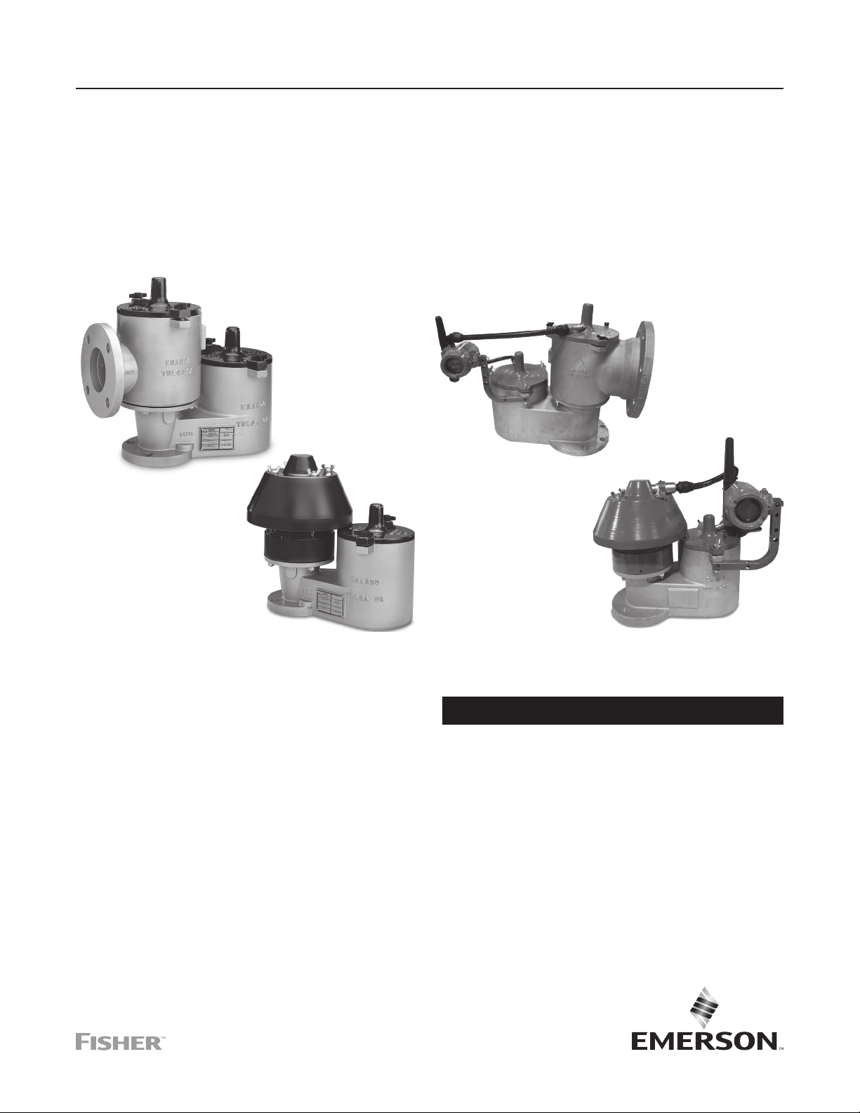
Enardo ES-850 and Enardo ES-950 Series
Enhanced Sealing Enardo ES-850 and
Enardo ES-950 Series Pressure/Vacuum
Relief Valve
P1854
MODEL ENARDO ES-850
P1854
MODEL ENARDO ES-950 MODEL ENARDO ES-950
Figure 1. Enardo ES-850 and Enardo ES-950 Series
Pressure/Vacuum Relief Valve
Table of Contents
Introduction ........................................................................... 2
Specifications .......................................................................2
Product Identification and Marking ....................................... 5
Principle of Operation ........................................................... 5
Installation ............................................................................8
Maintenance ....................................................................... 11
Adjustments ........................................................................ 14
Valve Repair ....................................................................... 16
MODEL ENARDO ES-850
Figure 2. Enardo ES-850 and Enardo ES-950 Series
with Smart Wireless option
WARNING
▲
Failure to follow these instructions or to
properly install and maintain this equipment
could result in an explosion, re and/or
chemical contamination causing property
damage and personal injury or death.
Fisher™ pressure/vacuum relief valve
must be installed, operated and maintained
in accordance with federal, state and
local codes, rules and regulations,
and Emerson Process Management
Regulator Technologies Tulsa, LLC
(Emerson) instructions. These units are not
designed or intended for use in mobile, high
vibration or high acceleration applications.
Outside North America Only
Page 2

Enardo ES-850 and Enardo ES-950 Series
Specications
The Specications section on this page provides specications for the Enardo ES-850 and Enardo ES-950 Series pressure/
vacuum relief valve. Specication is stamped on the nameplate attached to the relief valve. Refer to Product Identication and
Marking section for the nameplate details.
Available Construction
See Figures 3 and 4
Inlet Connection Sizes
2 through 12 in. / 50 through 300 mm
Pressure Ranges
(1)(2)
For sizes up to 6 in. / 150 mm
0.5 to 32 oz./sq. in.
1.0 to 55 in. w.c.
2.15 to 138 mbar
22 to 1406 mm w.c.
For sizes 8 in. / 200 mm and larger
0.5 to 24 oz./sq.in.
1.0 to 41.5 in. w.c.
2.15 to 103 mbar
22 to 1055 mm w.c.
Vacuum Pressure Ranges
(1)(2)
Vacuum Pressure Ranges
For sizes 8 in. / 200 mm and larger
0.4 to 24 oz./sq. in.
1.0 to 41.5 in. w.c.
1.72 to 103 mbar
17.6 to 1055 mm w.c.
Construction Materials
Housing: Aluminum, Stainless steel or Carbon steel
Seat / Pallet: 316 Stainless steel
Pallet Seal: Nitrile (NBR), Fluorinated Ethylene
(3)
Propylene (FEP), Fluorocarbon (FKM) or
Fluorosilicone (FVMQ)
Hardware: Zinc-plated Carbon steel or Stainless steel
Weights: Zinc-plated Carbon steel, Stainless steel
or Lead
Gaskets: Nitrile (NBR), FEP, Fluorocarbon (FKM) or
Fluorosilicone (FVMQ)
(1)(2)
(continued)
(3)
For sizes up to 6 in. / 150 mm
0.4 to 32 oz./sq. in.
1.0 to 55 in. w.c.
1.72 to 138 mbar
17.6 to 1406 mm w.c.
1. The pressure limits in this Instruction Manual and any applicable standard or code limitation should not be exceeded.
2. Pressure or vacuum setting has an increment of 0.5 oz./sq.in., 0.5 in. w.c. or 2.2 mbar.
3. 8, 10 and 12 in. / 200, 250 and 300 mm sizes limited to a maximum pressure relief setting of 16 oz./sq.in. / 69 mbar when a vacuum relief setting of 0.4 oz./sq. in. / 1.72 mbar is used.
Failure to correct trouble could result in a
hazardous condition. Call a qualied service
person to service the unit. Installation,
operation and maintenance procedures
performed by unqualied person may result
in improper adjustment and unsafe operation.
Either condition may result in equipment
damage or personal injury. Only a qualied
person shall install or service the pressure/
vacuum relief valve.
Introduction
Scope of the Manual
This Instruction Manual provides instructions for installation,
maintenance and parts ordering information for the
Enardo ES-850 and Enardo ES-950 Series pressure/vacuum
relief valve (PVRV).
Product Description
Enardo ES-850 and Enardo ES-950 Series
The Enardo ES-850 and Enardo ES-950 Series pressure/
vacuum relief valves provide protection against positive or
vacuum overpressure and prevent air intake and evaporative
losses of product while helping to contain odorous and
potentially explosive vapors.
The Enardo ES-850 Series provides pressure and vacuum relief
in applications that require hazardous vapors to be piped away
rather than released into the atmosphere.
The Enardo ES-950 Series valve provides pressure and
vacuum relief for normal venting requirements while maintaining
a safe internal working pressure to prevent the routine expulsion
of waste gas to the atmosphere.
• Model Enardo ES-850: Pressure/Vacuum Relief Valve —
Pipe-Away
• Model Enardo ES-851: Top Mount Pressure or Side
Mount Vacuum Relief Valve — Pipe-Away
• Model Enardo ES-950: Pressure/Vacuum Relief Valve —
Vent-to-Atmosphere
• Model Enardo ES-951: Pressure Relief Valve —
Vent-to-Atmosphere
• Model Enardo ES-952: Top Mount Vacuum Relief
Valve — End-of-Line
• Model Enardo ES-953: Side Mount Vacuum Relief Valve
Outside North America Only
2
Page 3
Enardo ES-850 and Enardo ES-950 Series
Model - Inlet Size x Outlet Size - Housing Material Pallet and Seat Material Pallet Seal Material Body/Seat/Lid Seal Material -
Enardo ES-850 2 to 12 in. 3 to 14 in. 1 = Aluminum
Pressure Units Pressure Setting / Vacuum Units Vacuum Setting - Weight Material - Options
z = oz./sq.in.
n = in. w.c.
mm = mm w.c.
mb = mbar
0.5 to 32.0 oz./sq.in.
0.86 to 55.0 in. w.c.
22 to 1406 mm w.c.
2.2 to 138 mbar
MODEL ENARDO ES-850 PRESSURE/VACUUM RELIEF VALVE MODEL NUMBER
4 = 316SST
5 = Carbon Steel
z = oz./sq.in.
n = in. w.c.
mm = mm w.c.
mb = mbar
2 = 316SST 1 = FEP
0.5 to 32.0 oz./sq.in.
0.86 to 55.0 in. w.c.
22 to 1406 mm w.c.
2.2 to 138 mbar
C = CS ZP
S = SST
L = Lead
2 = Nitrile (NBR)
3 = Fluorocarbon (FKM)
4 = Fluorosilicone (FVMQ)
0 = No Options
F = Flat Face Flange (standard for Alumunim)
R = Raised Face Flange (standard for CS, SS)
X = Epoxy Coating
W1 = Wireless Pressure and Vacuum Monitoring
W2 = Wireless Pressure Monitoring Only
W3 = Wireless Vacuum Monitoring Only
W4 = Wired Pressure and Vacuum Monitoring
W5 = Wired Pressure Monitoring Only
W6 = Wired Vacuum Monitoring Only
1 = PTFE Body and FEP
Seat/Lid
2 = Nitrile (NBR)
3 = Fluorocarbon (FKM)
4 = Fluorosilicone (FVMQ)
Model - Inlet Size - Housing Material Pallet and Seat Material Pallet Seal Material Body/Seat/Lid Seal Material
Enardo ES-950 2 to 12 in. 1 = Aluminum
Pressure Units Pressure Setting / Vacuum Units Vacuum Setting - Weight Material - Options
z = oz./sq.in.
n = in. w.c.
mm = mm w.c.
mb = mbar
0.5 to 32.0 oz./sq.in.
0.86 to 55.0 in. w.c.
22 to 1406 mm w.c.
2.2 to 138 mbar
4 = 316SST
5 = Carbon Steel
z = oz./sq.in.
n = in. w.c.
mm = mm w.c.
mb = mbar
MODEL ENARDO ES-950 PRESSURE/VACUUM RELIEF VALVE MODEL NUMBER
Figure 3. Pressure/Vacuum Relief Valve Model Number
2 = 316SST 1 = FEP
0.5 to 32.0 oz./sq.in.
0.86 to 55.0 in. w.c.
22 to 1406 mm w.c.
2.2 to 138 mbar
2 = Nitrile (NBR)
3 = Fluorocarbon (FKM)
4 = Fluorosilicone (FVMQ)
C = CS ZP
S = SST
L = Lead
1 = PTFE Body and FEP Seat/Lid
2 = Nitrile (NBR)
3 = Fluorocarbon (FKM)
4 = Fluorosilicone (FVMQ)
0 = No Options
F = Flat Face Flange (standard for Alumunim)
R = Raised Face Flange (standard for CS, SS)
X = Epoxy Coating
W1 = Wireless Pressure and Vacuum Monitoring
W2 = Wireless Pressure Monitoring Only
W3 = Wireless Vacuum Monitoring Only
W4 = Wired Pressure and Vacuum Monitoring
W5 = Wired Pressure Monitoring Only
W6 = Wired Vacuum Monitoring Only
-
Outside North America Only
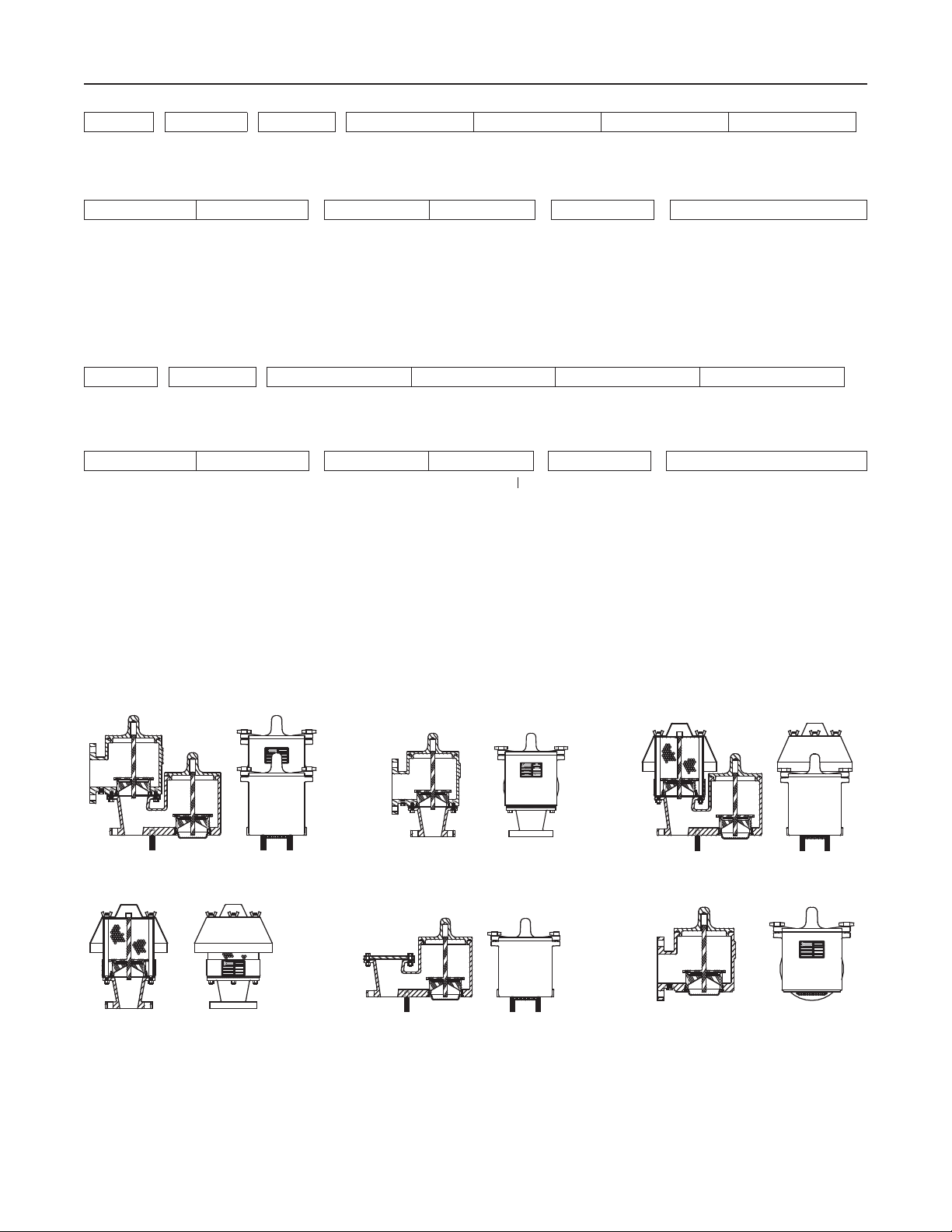
MODEL ENARDO ES-850 MODEL ENARDO ES-851 MODEL ENARDO ES-950
MODEL ENARDO ES-951 MODEL ENARDO ES-952 MODEL ENARDO ES-953
Figure 4. Enardo ES-850 and Enardo ES-950 Series Pressure/Vacuum Relief Valve Available Models
3
Page 4
Enardo ES-850 and Enardo ES-950 Series
Table 1. Model Enardo ES-850 Weights
INLET CONNECTION OUTLET CONNECTION
In. mm In. mm Lb kg Lb kg Lb kg Lb kg
2 50 3 80 29 13 80 36 0.9 0.3 0.5 0.2
3 80 3 80 31 14 85 39 0.9 0.3 0.5 0.2
3 80 4 100 33 15 90 41 0.9 0.3 0.5 0.2
4 100 6 150 57 26 144 65 2.3 1.0 1.3 0.6
6 150 6 150 62 28 155 70 2.3 1.0 1.3 0.6
6 150 8 200 70 32 178 81 2.3 1.0 1.3 0.6
8 200 10 250 161 73 485 220 7.8 3.5 4.5 2.0
10 250 10 250 166 75 503 228 7.8 3.5 4.5 2.0
10 250 12 300 172 78 525 238 7.8 3.5 4.5 2.0
12 300 12 300 175 79 532 241 7.8 3.5 4.5 2.0
12 300 14 350 208 94 622 282 7.8 3.5 4.5 2.0
1. Unit weights indicate Net Weight of valve in pounds and kilograms at standard set pressure (0.5 oz/sq. in. pressure – 0.5 oz/sq. in. vacuum). It does not include shipping crate or box.
2. Multiply the relief setting by the value shown to determine the weight of the calibration weights used to achieve the desired relief setting.
3. Values shown for calibration weights are for reference purposes only. They are not intended to be used for determination of valve relief setting.
WEIGHT
(ALUMINUM)
WEIGHT
(STAINLESS STEEL OR
CARBON STEEL)
Table 2. Model Enardo ES-950 Weights
INLET CONNECTION
In. mm Lb kg Lb kg Lb kg Lb kg
2 50 21 10 54 24 0.9 0.3 0.5 0.2
3 80 23 10 58 26 0.9 0.3 0.5 0.2
4 100 41 19 110 50 2.3 1.0 1.3 0.6
6 150 45 20 123 56 2.3 1.0 1.3 0.6
8 200 123 56 362 164 7.8 3.5 4.5 2.0
10 250 129 59 383 174 7.8 3.5 4.5 2.0
12 300 144 65 405 184 7.8 3.5 4.5 2.0
1. Unit weights indicate Net Weight of valve in pounds and kilograms at standard set pressure (0.5 oz/sq. in. pressure – 0.5 oz/sq. in. vacuum). It does not include shipping crate or box.
2. Multiply the relief setting by the value shown to determine the weight of the calibration weights used to achieve the desired relief setting.
3. Values shown for calibration weights are for reference purposes only. They are not intended to be used for determination of valve relief setting.
WEIGHT
(ALUMINUM)
WEIGHT
(STAINLESS STEEL OR
CARBON STEEL)
(1)
WEIGHT OF CALIBRATION WEIGHTS REQUIRED TO
ACHIEVE DESIRED RELIEF SETTING
Weight per oz/sq. in. Weight per in. w. c.
(1)
WEIGHT OF CALIBRATION WEIGHTS REQUIRED TO ACHIEVE
Weight per oz/sq. in. Weight per in. w. c.
DESIRED RELIEF SETTING
(2)(3)
(2)(3)
Smart Wireless Monitoring Option
WARNING
▲
The surface resistivity of the antenna
assembly when the optional transmitter
is installed is greater than 1 GΩ. To avoid
electrostatic charge build up, it must not be
rubbed or cleaned with solvents or dry cloth.
The Smart Wireless Monitoring Option is available
with PVRV Models Enardo ES-850 (Pipe-away) and
Enardo ES-950 (Vent-to-atmosphere). This option allows the
remote sensing and “OPEN/CLOSED” value transmission
of the open or closed status of the pressure vent, the
vacuum vent or both. Use Option Code WP for pressure vent
monitoring, Option Code WV for vacuum vent monitoring
or WPV for the monitoring of both at the end of the model
string. Knowing whether a PVRV is open or closed can
enable immediate response to prevent problems related to
safety, emissions and quality of the tank contents.
4
The following are a few specic examples of how this added
visibility can help prevent problems:
Example #1 – Redundant PVRV’s
Redundant PVRV’s are commonly used for added safety. If
the primary PVRV fails closed or partially-closed, then the
backup PVRV automatically takes over. This is achieved by
establishing a pressure set point that is slightly higher for
the backup device. In this way, if the primary PVRV fails, the
tank remains protected. But redundancy is lost and should
be addressed as soon as possible. But how will you know
if this has occurred? Monitoring the open/closed position
of the backup PVRV can provide quick identication of this
issue, for either the pressure or vacuum side. Under normal
conditions, the backup PVRV remains closed. If the backup
PVRV is open, this points to either the primary PVRV not
functioning as expected or a separate pressure control
problem in the tank system that is causing both PVRV’s to
be open. Ideally, the wireless monitoring of both primary and
backup devices is preferred in order to gain the most insight.
Outside North America Only
Page 5
Enardo ES-850 and Enardo ES-950 Series
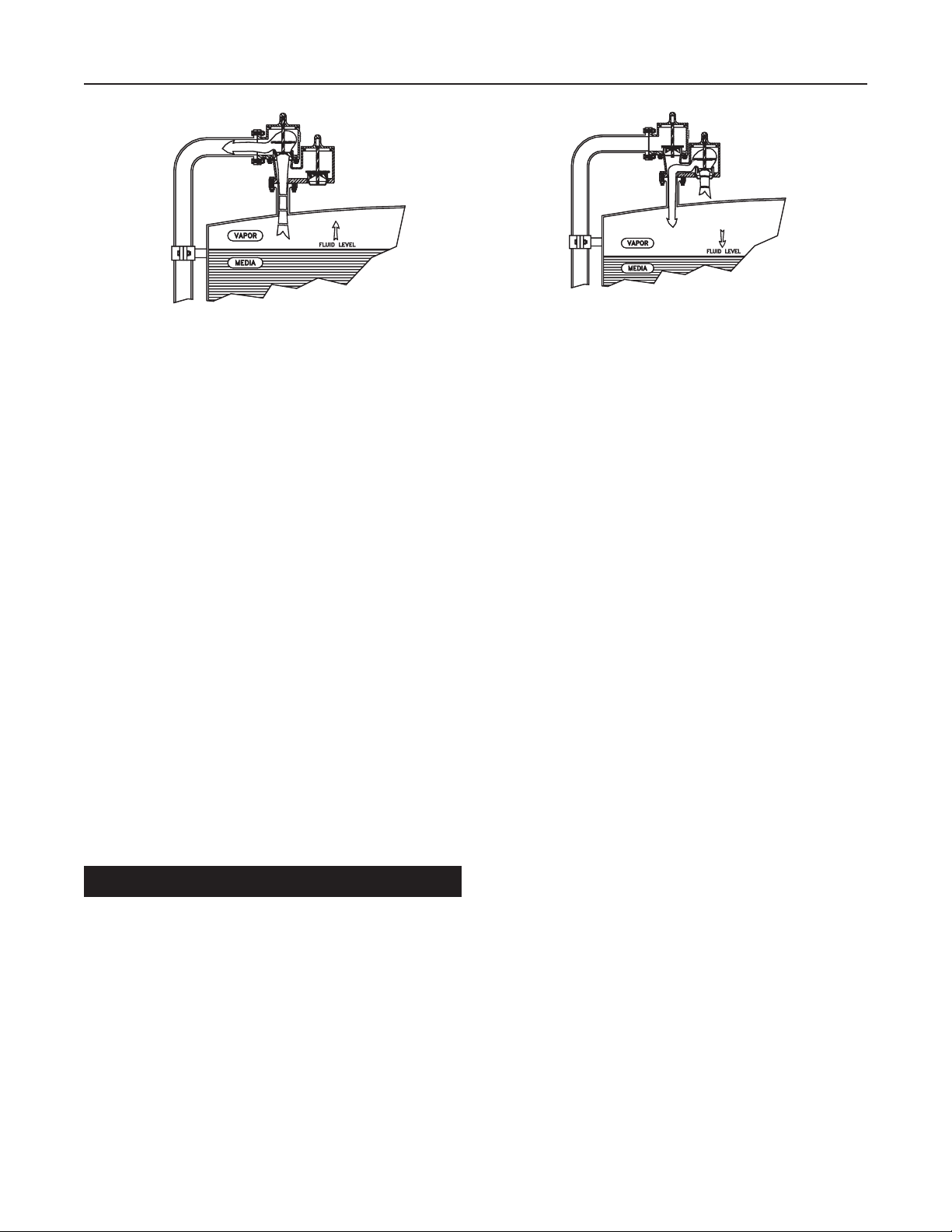
PRESSURE FLOW
Figure 5. Pressure and Vacuum Flow
Further troubleshooting can then be performed and the
problem can be detected and addressed.
Example #2 – Tank Blanketing
Tank blanketing is sometimes used in order to inert the vapor
space in a tank for added safety. A tank blanketing regulator
controls the inow of nitrogen or another blanketing gas
by responding to a low pressure set point. In this scenario,
a PVRV (vacuum side) generally acts as a backup to the
blanketing regulator. If the blanketing system fails for some
reason, the PVRV automatically takes over, as its set point is
slightly higher than that of the regulator. But once again, how
is one to know that this has occurred? A wireless-monitored
PVRV would indicate that the vacuum side is open. Under
normal operation, it should be closed.
Example #3 – Emergency Vent
A storage tank’s emergency vent should remain closed,
except in abnormal conditions. If an emergency vent is also
remotely monitored, and found to be open, then there may
be a pressure control issue somewhere in the system. In this
scenario, the PVRV should also be open. If it is not, it could
be part of the issue. Again, a wireless-monitored PVRV can
readily provide this information.
Product Identication and Marking
CAUTION
△
VACUUM FLOW
Hazardous Locations
Fisher™ pressure/vacuum relief valves are available with
outer housings of carbon steel, stainless steel or aluminum,
as indicated in Figure 5.
Nameplate
A nameplate is attached to the valve and contains the
following information:
• Model Number – Ex. VALVE, Enardo ES-950-4-1211
• Conn. Flange Size and Rating – Ex. 4 in.
• Serial Number
• Tag Number (Optional)
• Year – Ex. 08
Principle of Operation
Enardo ES-850 and Enardo ES-950 Series
The Enardo ES-850 and Enardo ES-950 Series pressure/
vacuum relief valves maintain a tight seal until system
pressure or vacuum exceeds the set pressure of the valve.
Set pressure is determined by stacking a series of weights
onto the valve pallet unless the pressure and vacuum set
points have been specied for the minimum settings. When
overpressure occurs, the weighted pallet lifts, breaking the
seal between the seat and pallet. This allows vapors to pass
through the valve orice and relieve pressure buildup. The
valve reseals upon relief and remains sealed.
Outside North America Only
As part of the legacy Model Enardo 850/
Enardo 950 ATEX certication, an
ignition risk analysis was performed.
Grounding of the unit is not deemed to be
necessary because all conducting parts
of the equipment are arranged such that
a dangerous potential dierence cannot
exist between them. However, grounding or
bonding allowances can be made at user
request if internal, local or national codes or
standards require.
It is important to know that relieving vapors near the set
pressure in a continuous manner may cause the pallet to
utter or oscillate inside the valve chamber. This is common
to products of this type. Operating the valve with utter or
oscillation may cause premature valve damage or wear over
time. Fisher pressure/vacuum relief valve ow charts and
sizing program results designate the “utter zone” to assist
with correct valve sizing. Contact your local Sales Oce with
any questions or additional assistance.
5
Page 6

Enardo ES-850 and Enardo ES-950 Series
LID AND UPPER
GUIDE
OUTLET FLANGE
VALVE PALLET
LID O-RING
PRESSURE CHAMBER
LID AND UPPER
GUIDE
VALVE SEAT
DRAIN PLUG
BODY ATTACHMENT
GASKET
GUIDE BUSHING
VENT ROD
VALVE PALLET
WEATHER
HOOD
VACUUM CHAMBER
VALVE PALLET STEM
VALVE PALLET SEAL
SEAT O-RING
INLET FLANGE
INSTALLATION STUD
MODEL ENARDO ES-850 PIPE-AWAY PRESSURE/VACUUM RELIEF VALVE
UPPER GUIDE
PRESSURE CHAMBER
(ATMOSPHERE)
LID AND UPPER
GUIDE
Outside North America Only
VACUUM CHAMBER
VALVE SEAT
VALVE PALLET STEM
VALVE PALLET SEAL
INLET FLANGE
VACUUM SCREEN
VACUUM SEAT RETAINER
MODEL ENARDO ES-950 VENT-TO-ATMOSPHERE PRESSURE/VACUUM RELIEF VALVE
Figure 6. Models Enardo ES-850 and Enardo ES-950 Pressure/Vacuum Relief Valve Assembly
6
Page 7

Enardo ES-850 and Enardo ES-950 Series
WIRELESS LID
WIRELESS STEM
SENSOR
TRANSMITTER
WIRELESS LID
SENSOR
WIRELESS
STEM
Figure 7. Model Enardo ES-850 with Smart Wireless Option
CONDUIT
CONDUIT
WIRELESS HOOD
WIRELESS STEM
VENT ROD
SENSOR
BRACKET
SET SCREW
SLEEVE
TRANSMITTER
WIRELESS LID
SENSOR
WIRELESS
STEM
Figure 8. Model Enardo ES-950 with Smart Wireless Option
CONDUIT
CONDUIT
Outside North America Only
7
Page 8

Enardo ES-850 and Enardo ES-950 Series
Installation
Enardo ES-850 and Enardo ES-950 Series
WARNING
▲
Take all necessary precautions and safety
measures when lifting valves into place
to prevent unbalanced load situations.
Do not install calibration weights or pallet
assemblies prior to mounting and installation
of valve. Special care must be taken during
installation to prevent damage to the seat
sealing surface.
Wear protective gloves and clothing
to prevent skin contact when handling
lead weights. Wear eye protection. Avoid
breathing dust/fumes/mist/vapors/spray.
Do not eat, drink or smoke while using the
product. Avoid release to the environment.
Wash hands with soap and water after
handling. Keep away from excessive heat
and open flames.
If lead weights need to be disposed of, follow
all local, regional and national regulatory
requirements for the safe and proper
disposal of lead.
2. Remove valve pallets from the unit. Separate the
protective cardboard coverings from the pallet stems
and seals. Gently clean the seal with a suitable solvent
and lint free, nonabrasive cloth to remove any dirt/
particles and achieve good seal tightness. Be careful not
to damage the pallet seal surface.
REMOVE CARDBOARD FROM PALLET STEMS
All product congurations use similar
packing methods.
CARDBOARD
Note
Make sure line is free of hazardous vapors
before installing or servicing the valve.
Product material of construction can include
aluminum, carbon steel and stainless steel.
Care should be taken to avoid mechanical
impacts that could result in a spark.
1. Loosen fasteners on top of the valve and remove the lid,
hood or guide.
CARDBOARDS
REMOVE CARDBOARD FROM PALLET STEMS
Outside North America Only
3. Reinsert uncovered valve pallets back into the unit.
Make sure that the lower stem is being guided by the
saber guides before lowering the pallet onto the seat
to avoid hitting the seat sealing edge with an o-set
pallet . If the pallet appears to be o-center to the
valve chamber, or if there is diculty positioning the
lid or guide, carefully inspect the pallet to ensure it is
inserted properly.
8
Page 9

Enardo ES-850 and Enardo ES-950 Series
4. Remove any protective ange covers.
Note
For more details on using weights
to adjust the pallet setting, read the
Adjustments section.
CAUTION
△
Use care when installing weights and
securing lids to avoid getting pinched.
5. Reinstall pressure and/or vacuum pallet assemblies into
their respective openings. Install the setting weights
(if required) by engaging the hole in the weight on the
appropriate pallet assembly stem.
5.1. The weights are marked with their pressure
equivalents and are shipped outside of the valve
chamber. Verify that the appropriate weights are
being installed to provide the specied pressure
and/or vacuum setting. Refer to the nameplate data
to verify the specied factory settings.
Note
Make sure that the pallet assembly stem
positively engages the stem guide hole in the
hood or cover. Each pallet assembly must be
free to move upwards, with the pallet stem
travelling into the stem guide.
CAUTION
△
Use care when installing weights and
securing lids to avoid getting pinched.
6. Install the covers and/or hood.
7. Re-use existing wing nuts or nuts and tighten to secure
covers/hoods in position.
8. Attach the valve to the appropriate mating ange using
appropriate ange gasket which is compatible with
process conditions (customer provided). To ensure
proper function, install the valve to a level surface,
not greater than 1° o horizontal so the pallet will
move vertically. Valves that are tilted during usage
may suer premature damage or wear, and may have
more leakage.
For proper bolt torquing of the valve connecting ange to the
piping, please refer to Tables 3 to 5.
5.2. To adjust valve settings higher than minimum,
use the weights to increase the pressure setting.
Weights are packed separately within the unit
shipping package and are labelled “PRESSURE”
and/or “VACUUM”. If weights are shipped with the
unit, they should be installed onto the pallets in the
valve chamber in which they are labelled. Gently
slide the weights onto the pallet stem and down on
top of the valve pallet.
For 10 in. / 250 mm FEP pallets make sure to
put the PTFE (Teon
before adding the weights.
®
) spacer on top of the pallet
Smart Wireless Monitoring
WARNING
▲
Do not thread wireless sensor too far into
lid. Sensor may contact pallet stem and
prevent valve from opening properly. This
condition may result in equipment damage or
personal injury.
Units with Smart Wireless are shipped as self-contained
and already connected. The only connection required is
installation of the transmitter battery (shipped separately)
which is intrinsically safe and does not require a
hot-work permit.
1. Install valves with the Smart Wireless monitoring option
in a similar manner to the standard PVRVs with a few
differences. Remove any cardboard or other packaging
from the inner chambers. Remove the lid(s) and/
or hood to allow insertion of the appropriate weights
during installation.
2. Remove any lid with the sensing equipment threaded
into it as a single unit. The sensor should remain
engaged with the lid during this process. Position all
Outside North America Only
Teon® is a mark owned by E.I. du Pont de Nemours and Co.
9
Page 10

Enardo ES-850 and Enardo ES-950 Series
Table 3. Torque Specifications - Raised Face Flange, Steel Only
NOMINAL PIPE DIAMETER NUMBER OF BOLTS BOLT DIAMETER, IN. TORQUE, FT-LBS
2 4 0.63 35
3 4 0.63 60
4 8 0.63 43
6 8 0.75 80
8 8 0.75 109
10 12 0.88 101
12 12 0.88 135
14 12 1.00 168
Assumptions: Use of SAE grade 5 bolts or studs or stronger. No lubricant. Compressed mineral ber material or similar.
Notes: If lubricant is used on bolts, apply torque reduction factor listed in Table 5. For best results, hardened steel washers should be used on all cast ange bolted connections.
Table 4. Torque Specifications - Flat Face Flange, Steel or Aluminum
NOMINAL PIPE DIAMETER NUMBER OF BOLTS BOLT DIAMETER, IN. TORQUE, FT-LBS
2 4 0.63 32
3 4 0.63 47
4 8 0.63 32
6 8 0.75 49
8 8 0.75 68
10 12 0.88 69
12 12 0.88 98
14 12 1.00 138
Assumptions: Use of SAE grade 5 bolts or studs or stronger. No lubricant. Elastomer <70 Durometer Shore A.
Notes: Flat faced anges should never be mated to a raised face ange for installation. If lubricant is used on bolts, apply torque reduction factor listed in Table 5. For best results,
hardened steel washers should be used on all cast ange bolted connections.
Table 5. Torque Reduction Factors per Lubricant
DESCRIPTION COEFFICIENT OF FRICTION MULTIPLY TORQUE VALUE IN TABLE BY
Machine Oil f = 0.15 0.75
API SA2 Grease f = 0.12 0.60
Nickel-based Lubricant f = 0.11 0.55
Copper-based Lubricant f = 0.10 0.50
Heavy-Duty Lubricating Paste f = 0.06 0.30
Outside North America Only
10
Page 11

Enardo ES-850 and Enardo ES-950 Series
sensors within 0.100 in. of the pallet stem. Maintain
this critical distance. If the sensor location within a lid is
altered, re-test the unit to ensure proper functioning of
the sensor and transmitter. If this is the case, re-apply
thread sealant to mitigate any leakage of the sensor/
lid interface.
Figure 9. Model Enardo ES-850, Installation of Weights
3. For the Model Enardo ES-950 PVRVs containing hoods,
the sensor is located at a proper distance away from
the stem by using a sleeve, bracket and set screw. The
sensor is held within the sleeve using two jam nuts.
Fasten the sleeve to the hood using a bracket. Using
a set screw, mate the bracket and sleeve to ensure
that the sensor is in the proper location and cannot
be adjusted. When installing weights, lift the hood and
sensor/bracket/sleeve off the vent rods as one. Remove
the sensor/bracket/sleeve from the hood and install the
weights. Reverse the process to reassemble the hood
and sensor.
Figure 10. Model Enardo ES-950,
Installation of Weights (continued)
Maintenance
Enardo ES-850 and Enardo ES-950 Series
WARNING
▲
Wear protective gloves and clothing to prevent
skin contact when handling lead weights. Wear
eye protection. Avoid breathing dust/fumes/
mist/vapors/spray. Do not eat, drink or smoke
while using the product. Avoid release to the
environment. Wash hands with soap and water
after handling. Keep away from excessive heat
and open flames. Ensure that all proper safety
procedures and safeguards are followed when
working on units, especially if they are in the
elevated position.
Make sure line is free of hazardous vapors
before installing or servicing the valve.
Observe all applicable safety requirements.
Only qualied and trained personnel
shall perform maintenance functions in
hazardous locations.
Valves should be removed from the location
having a potentially explosive atmosphere
and taken to a safe location for repair
and maintenance.
Outside North America Only
Figure 10. Model Enardo ES-950, Installation of Weights
CAUTION
△
When removing and installing seats, ensure
to handle it with care to prevent damage
(scratches, nicks, etc.) to the sealing surface.
11
Page 12

Enardo ES-850 and Enardo ES-950 Series
For preventive maintenance of the Fisher™ pressure/
vacuum relief valve, refer to the following instructions.
1. Loosen the fasteners on top of the valve and remove
the lid, hood or guide.
3. Inspect the pallets for any damage or buildup that
may aect its sealing characteristics or its ability to
move properly inside the valve. Gently clean the seal
with a suitable solvent and lint free, nonabrasive
cloth to remove any dirt/particles and achieve good
seal tightness.
4. Clear away any buildup on the weights or on
the housing.
2. Remove any valve pallets and weights from the unit.
Keep in mind that these will be reinstalled, so keep track
of the chamber from which they were removed.
12
Outside North America Only
5. Inspect the valve seats installed in the unit. The sealing
surfaces should be smooth and free of nicks or buildup.
A good, clean seat sealing surface free from defects is
essential to achieving a tight seal. Check the guides for
anything that may keep the valve pallet from moving
properly inside the valve. If necessary, gently clean the
seats with a suitable solvent and nonabrasive cloth.
Page 13

Enardo ES-850 and Enardo ES-950 Series
6. If the valve has a lid, clean any buildup that may exist
in or around the guide hole located in the center of
the part.
9. Reinstall weights onto their appropriate valve pallets.
7. If the valve is tted with a screen of some type, clear
away any blockage that may impede proper ow.
8. Reinstall valve pallets and weights into their proper
chambers. Make sure the lower stem on the pallet
is centered into the valve seat. If the pallet appears
to be o-center to the valve chamber, or if there is
diculty positioning the lid or guide, the pallet may be
inserted improperly.
Spirolox® is a mark owned by Smalley Steel Ring Company.
Outside North America Only
10. Replace any lid, hood or guide that was previously
removed and fasten securely. When tightening down
lids, make sure the O-ring in each lid has full contact
with the sealing surface.
11. For seat removal, see Figure 6 for the valve
conguration drawings. The valve seats are installed in
machined bores in both the upper body (pressure) and
in the lower body (vacuum) and are tted with O-ring
seals. Remove the upper body seat by removing the
upper body casting (Model Enardo ES-850) or the Vent
Hood assembly (Model Enardo ES-950). Then remove
the seat from the bore. The lower seat (vacuum) is
retained by a Spirolox® retaining ring. Remove this ring
with a at-bladed screwdriver as shown above.
13
Page 14

Enardo ES-850 and Enardo ES-950 Series
PLACE RETROFIT STICKER NEXT TO VALVE NAMEPLATE.
Figure 11. Model Enardo 950 PVRV Retrofit Sticker Placement
Smart Wireless Monitoring Maintenace
Remove ring using a at-bladed screwdriver
12. For seat replacement, the seats are installed in the
reverse order of the removal. Make sure the bores are
clean and that the O-ring seals are not damaged. Use a
light lubricant when replacing the O-ring and seat.
Retrot Kits
The stainless steel seats, pallet assemblies and gaskets
used in the Enardo ES Series valves are completely
backwards compatible with Models Enardo 850/Enardo 950
valves already installed; even those with PPS pallets and
seats. Existing valves can be upgraded via readily available
retrot kits. Each kit contains one (1) Enardo ES Series
valve seat, one (1) seat O-ring, one (1) lid O-ring, one (1)
body gasket and one (1) pallet seal. For 8, 10 and 12 in.
valves that require FEP pallet seals, the retrot kit contains
a complete pallet assembly. For valves that have both
pressure and vacuum relief capabilities, two (2) retrot kits
are required to upgrade the entire valve. Note that the kits
are not specic to the venting function and can be used on
either the pressure or vacuum side of the valve.
Follow the instructions outlined in the Maintenance section of
this manual to replace the existing seats, gaskets and when
required, pallet assemblies. Once the upgrade is complete,
place the green retrot sticker that is included with each kit
next to the nameplate of the valve as shown in Figure 11.
The sticker provides conrmation that the valve has been
upgraded to the Enardo ES Series conguration.
1. Maintain Wireless Models Enardo ES-850 and Enardo ES-950
PVRVs in the same way as all standard Models
Enardo ES-850 and Enardo ES-950 PVRVs. Clean the
pallet and seat sealing surfaces, remove any buildup
of residues on the weights and ensure any screens are
not blocked.
2. Take certain precautions when cleaning the transmitter.
The surface resistivity of the antenna assembly when
the optional transmitter is installed is greater than 1 GΩ.
To avoid electrostatic charge build-up, it must not be
rubbed or cleaned with solvents or dry cloth.
Adjustments
The Fisher™ pressure/vacuum relief valves have wide range
of pressure and vacuum settings in units of ounces per
square inch (oz./sq.in.) or inches of water column (in. w.c.)
as indicated in the specication section of this instruction
manual. Standard Fisher valve pallets assemblies are
marked with a minimum equivalent pressure value in the
specied units. Installed alone has minimum settings of
1/2 oz./sq. in. or 1 in. w.c. The pallets are calibrated by the
seal support located on the bottom side of the pallet. The
pallet’s setting of 1/2 oz./sq.in. or 1 in. w.c. is etched into
the support. When a valve requires a setting higher than the
1/2 oz./sq.in. or 1 in. w.c. standard pallet setting, use weights
to increase the pallet’s setting up to the required setting.
The same seal support used with FEP seals on 8 in. /
200 mm and larger valves. In this case, the base calibration
of the pallet assembly can be determined by examining the
upper and lower guide stems. Pallet assemblies calibrated
to 1.0 in. w.c. or 25 mm w.c. will have stems fabricated using
solid bar stock. Pallet assemblies calibrated to 0.5 oz./sq.in.
or 2.2 mbar will have stems that have been fabricated using
tubing with plugged ends.
Outside North America Only
14
Page 15

Enardo ES-850 and Enardo ES-950 Series
Figure 12. Weights on Pallet
Table 6. Valve Maintenance
PART REPLACEMENT
Simple replacement. Provided with gasket repair kit
Pallet Seals
Pallet Assemblies
Body Gaskets Requires disassembly. Provided with gasket repair kit
Seats
along with other gaskets. The pallet seals are fragile and should
be handled carefully to avoid damage. They must never be folded
or creased. Never use abrasive cleaners on a pallet seal.
Drop-in replacement. Requires removal of lid.
Replace pallet seal as needed. For best results replace entire pallet assembly.
Again, care must be taken not to damage the seals.
Requires O-ring gasket to be replaced as well.
Use care when removing and installing seats to prevent damage
(scratches, nicks, etc.) to the sealing surface.
Use a light lubricant when replacing the O-ring and installing the seat.
Additional calibration weights are marked with their
equivalent pressure value and should be added as
necessary to achieve the specied setting.
Fisher™ weights also come in units of ounces per square
inch (oz./sq. in.) or inches of water column (in. w.c.). The
individual setting of each weight is either etched or imprinted
into the weight. Emerson oers several dierent sizes of
pressure/vacuum relief valves. To ensure that the right
weight is placed on the right pallet, take note that the weights
and pallets that go together will have the same outside
diameter. Standard Fisher weights allow the user to stack in
increments of 1/2 oz./sq. in. or 1/2 in. w.c.
Pressure/vacuum relief valve is shipped with prepackaged
weight kits to set the valve pressure properly. The package
labelled “pressure” is for the pallet in the pressure chamber,
while the package labelled “vacuum” is for the pallet in the
vacuum chamber. All weights in these packages should be
installed. If one or neither of these packages is included with
your order, then they are not needed. For 8 in. / 200 mm
and larger valves that use FEP seals, a PTFE spacer is
included and must be installed on top of the pallet before any
calibration weights are added. The spacer is not used if no
additional calibration weights are needed.
If the pressure and vacuum weights are mixed together, sort
and reorganize the weights.
When installing weights for the Fisher pressure/vacuum
relief valve, check the required settings on the tag attached
to the valve. Add weights to the pallet to achieve the required
setting. If the relief valve’s setting is 6 oz./sq. in., add weights
with the total setting of 5-1/2 oz./sq. in. to the valve since
the pallet’s setting alone is 1/2 oz./sq. in. Hence, the valve
pressure setting is the sum of the settings of the pallet and
the weights. The relief pressure or vacuum setting is equal
to the sum of the pallet assembly and individual calibration
weight equivalent pressure value.
Outside North America Only
15
Page 16

Enardo ES-850 and Enardo ES-950 Series
Valve Repair
WARNING
▲
Make sure line is free of hazardous vapors
before installing or servicing the valve.
Observe all applicable safety requirements.
Only qualied and trained personnel
shall perform maintenance functions in
hazardous locations.
All replacement parts must be provided
by Emerson.
Remove the valve from the tank before attempting any
repairs beyond pallet assembly and weight maintenance as
described on Maintenance section.
Most repairs will consist of replacing pallet seals, lid gaskets
and in some cases, the body gaskets. The seats are also
replaceable if the need arises. These repairs are relatively
simple and can normally be handled by plant maintenance
personnel using common hand tools.
Most valve maintenance can be performed by the customer
or by a valve repair facility. See Table 6 for the proper
maintenance of the relief valve parts.
In most cases, it is not necessary to return the valves to
the factory. If the valve needs to be tested and certied at
a specied pressure and/or vacuum, return it to the factory
or send it to a qualied valve repair facility that is capable
of performing the necessary tests in accordance with
API Bulletin 2521 recommendations.
Contact your local Sales Oce with any questions or
additional assistance needed for repairing your valve.
Webadmin.Regulators@emerson.com
Fisher.com
Emerson Automation Solutions
Americas
McKinney, Texas 75070 USA
T +1 800 558 5853
+1 972 548 3574
Tulsa, OK 74146 USA
T +1 918 662 6161
Europe
Bologna 40013, Italy
T +39 051 419 0611
Facebook.com/EmersonAutomationSolutions
LinkedIn.com/company/emerson-automation-solutions
Twitter.com/emr_automation
Asia Pacic
Singapore 128461, Singapore
T +65 6770 8337
Middle East and Africa
Dubai, United Arab Emirates
T +971 4 811 8100
D104632X012 © 2021 Emerson Process Management Regulator
Technologies, Inc. All rights reserved. 02/21.
The Emerson logo is a trademark and service mark of Emerson
Electric Co. All other marks are the property of their prospective owners.
Fisher™ is a mark owned by Fisher Controls International LLC, a business
of Emerson Automation Solutions.
The contents of this publication are presented for informational purposes
only, and while every eort has been made to ensure their accuracy,
they are not to be construed as warranties or guarantees, express or
implied, regarding the products or services described herein or their use
or applicability. All sales are governed by our terms and conditions, which
are available upon request. We reserve the right to modify or improve the
designs or specications of such products at any time without notice.
Emerson Process Management Regulator Technologies, Inc does not
assume responsibility for the selection, use or maintenance of any
product. Responsibility for proper selection, use and maintenance of any
Emerson Process Management Regulator Technologies, Inc. product
remains solely with the purchaser.
Outside North America Only
 Loading...