

Page 1

Mini Audio System
with Digital Tuner, CD Player
and Remote Control
OWNER’S MANUAL
ES1
Visit our web site at www.emersonradio.com
Page 2
BEFORE WE BEGIN
Thank you………………
for purchasing this Emerson Research audio product. The Emerson Research brand is your
assurance of quality, performance and value.
Our engineers have included many useful and convenient features in this product. Please be sure
to read this Owner’s Manual completely to make sure you are getting the maximum benefit from
each feature.
This product was manufactured using the highest quality components and standards of workmanship.
It was tested by Emerson Research inspectors and found to be in perfect working order before it left
our factory. However, there is always the chance that some problem may occur because of rough
handling during shipment to the retail store or to the final consumer.
If, after reading this Manual, you experience any problems with the operation of this product, please
refer to the instructions for obtaining service at the end of this Manual. Emerson Research and
Emerson Research retailers are committed to your satisfaction.
Once again, thanks for purchasing this Emerson Research audio product.
For future reference, record the serial number in the space provided.
Serial Number :
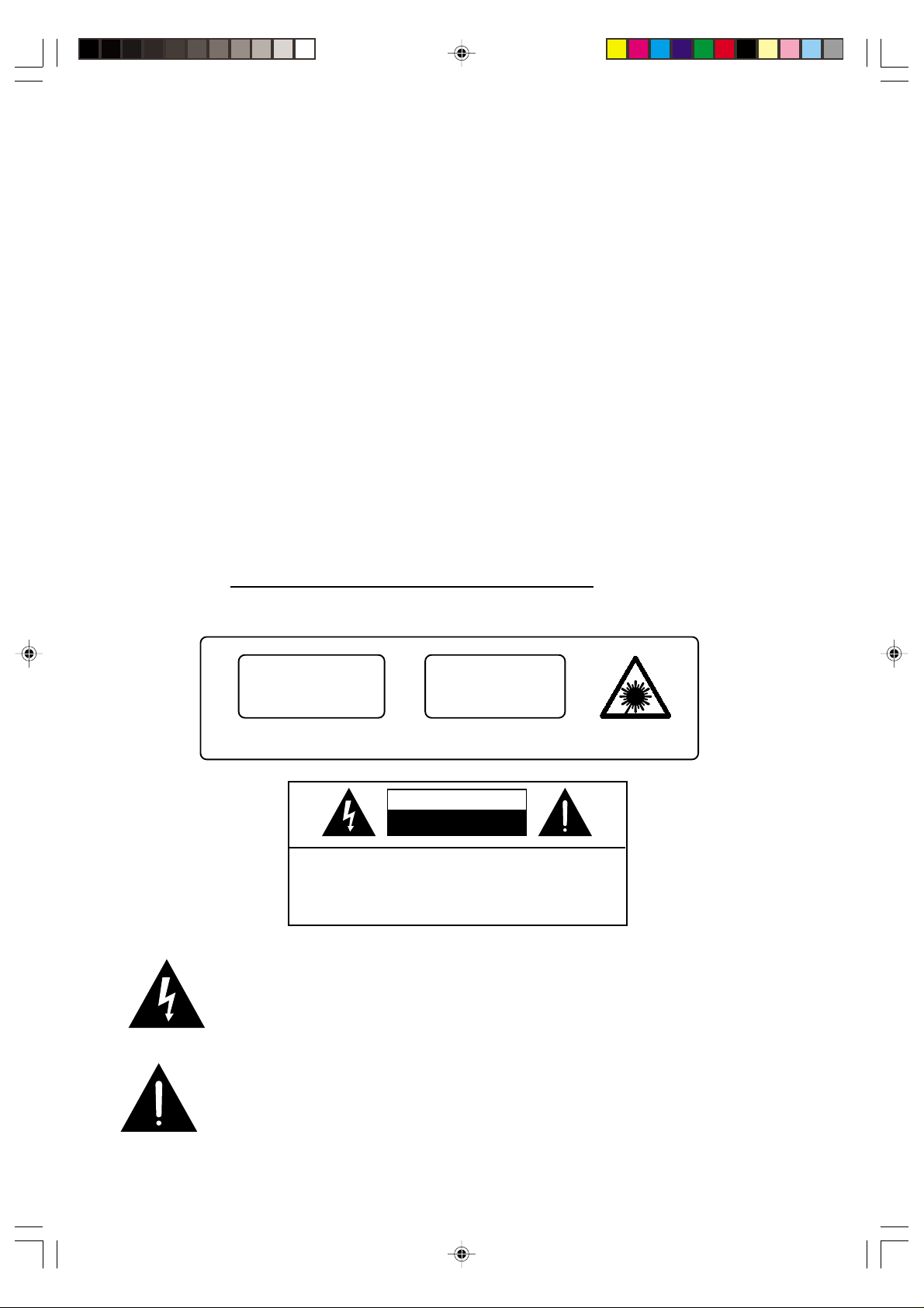
CLASS 1 LASER PRODUCT
CLASS 1 LASER PRODUCT
APPAREIL Á LASER DE CLASSE 1
PRODUCTO LASER DE CLASE 1
This product contains a low power Laser Device.
CAUTION
INVISIBLE LASER RADIATION
WHEN OPEN AND INTERLOCKS
DEFEATED.
AVOID EXPOSURE TO BEAM
CAUTION
RISK OF ELECTRIC SHOCK
DO NOT OPEN
CAUTION: TO REDUCE THE RISK OF ELECTRIC SHOCK,
DO NOT REMOVE COVER (OR BACK). NO USER
SERVICEABLE PARTS INSIDE. REFER SERVICING TO
QUALIFIED SERVICE PERSONNEL.
DANGEROUS VOLTAGE
Uninsulated Dangerous Voltage, that may be of sufficient magnitude to
constitute a risk of electric shock to persons is present within this product's
enclosure.
ATTENTION
The Owner's Manual contains important operating and maintenance
instructions.
For your safety, it is necessary to refer to the manual.
1
Page 3

IMPORTANT NOTES
• Avoid installing this unit in places exposed
to direct sunlight or close to heat radiating
appliances such as electric heaters, on top
of other stereo equipment tha radiates too
much heat, places lacking ventilation or
dusty areas, places subject to constant
vibration and/or humid or moist areas.
WARNING: TO PREVENT FIRE OR SHOCK HAZARD,
DO NOT EXPOSE THIS UNIT TO RAIN OR MOISTURE.
• Operate controls and switches as described
in the manual.
• Before turning on the power, make certain
that the connecting cords, if any, and power
cord are properly installed.
• When moving the set, be sure to first
disconnect the power cord and remove
cords connected to other equipment.
FCC INFORMATION
This equipment has been tested and found to comply with the limits for a Class B digital
device, pursuant to Part 15 of the FCC Rules. These limits are designed to provide reasonable
protection against harmful interference in a residential installation. This equipment generates,
uses, and can radiate radio frequency energy and, if not installed and used in accordance
with the instructions, may cause harmful interference to radio communications. However,
there is no guarantee that interference will not occur in a particular installation. If this
equipment does cause harmful interference to radio or television reception, which can be
determined by turning the equipment off and on, the user is encouraged to try to correct the
interference by one or more of the following measures:
• Reorient or relocate the receiving antenna.
• Increase the separation between the equipment and receiver.
• Connect the equipment into an outlet on a circuit different from that to which the
receiver is connected.
• Consult the dealer or an experienced radio/TV technician for help.
This device complies with Part 15 of the FCC Rules. Operation is subject to the following
two conditions:
(1) This device may not cause harmful interference, and
(2) This device must accept any interference received, including
interference that may cause undesired operation.
2
Page 4
PREPARATION FOR USE
UNPACKING AND SET-UP
• Carefully remove the unit from the carton and remove all packing material from the unit.
• Remove any labels or stickers which may be on the front or top of the set, but do not remove any
labels from the back or bottom.
• We suggest that you retain the original carton and packing materials in case it ever becomes
necessary to return your unit for service. This is the only sure way to protect the unit from damage
in transit.
• If you do dispose of the carton and packing materials, please do so properly.
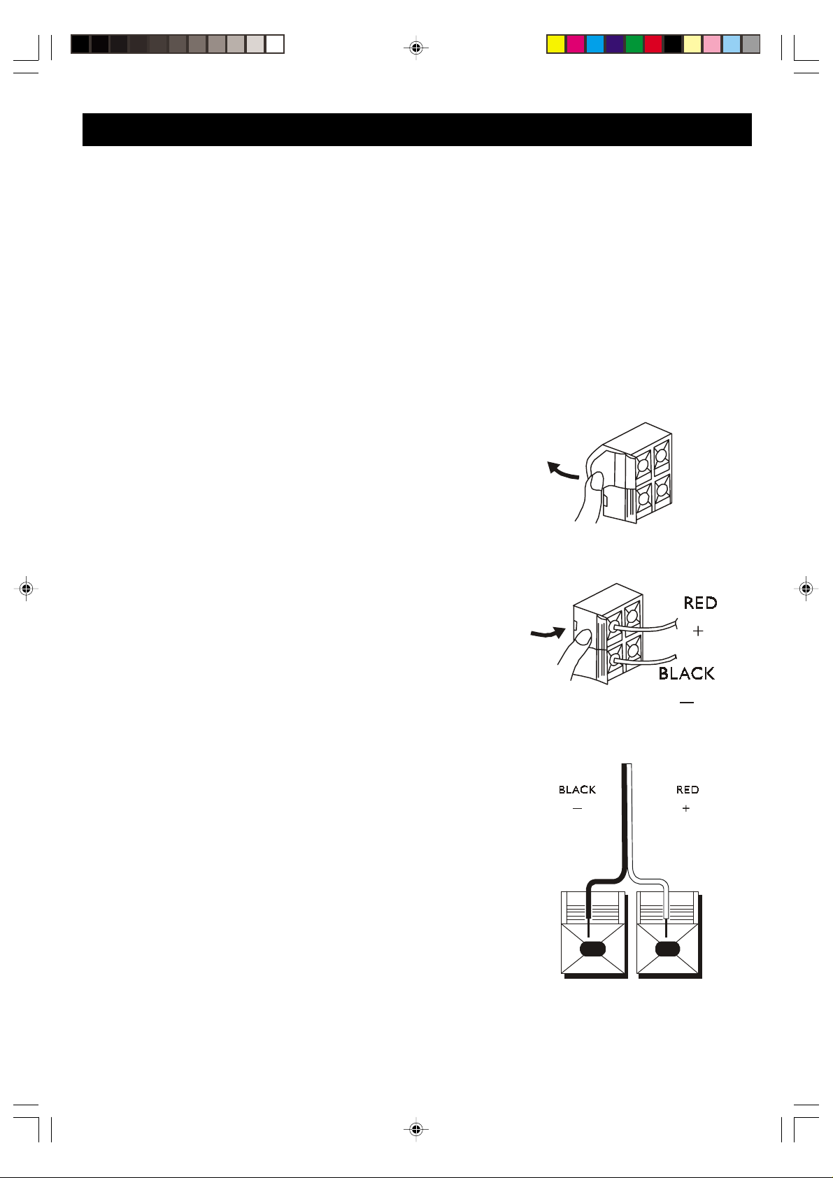
SPEAKER CONNECTION
The color-coded speaker cables must be connected to the
terminals on the back of the speaker cabinet and the back
of the main unit. Make both connections before you plug in
the unit.
T o insert wires into the terminals on the back of the main
unit:
1. Locate the bare ends of the wires and separate the
black wire from the red.
2. Lightly flip open the tab of the red (+) terminal, insert
the bare end of the red wire and snap the tab closed.
3. Repeat for the black (-) terminal and wire.
To insert wires into the terminals on the back of the
speaker:
1. Locate the bare ends of the wires and separate the
black wire from the red.
2. Press and hold down on the tab to open the red
terminal, then insert the red (+) wire.
3. Release to lock wire in terminal.
4. Use the same procedure to insert black (-) wire into
black terminal.
WARNING: Be sure to follow these instructions carefully. The system can be damaged if
speakers are improperly connected.
3
Page 5
POSITIONING THE SPEAKERS
The speakers may be positioned next to the main unit or separated as far as the wires will allow.
We recommend that you leave a gap of approximately 1/2” between the speakers and the main unit
so that vibration from the speaker does not cause the CD player to skip.
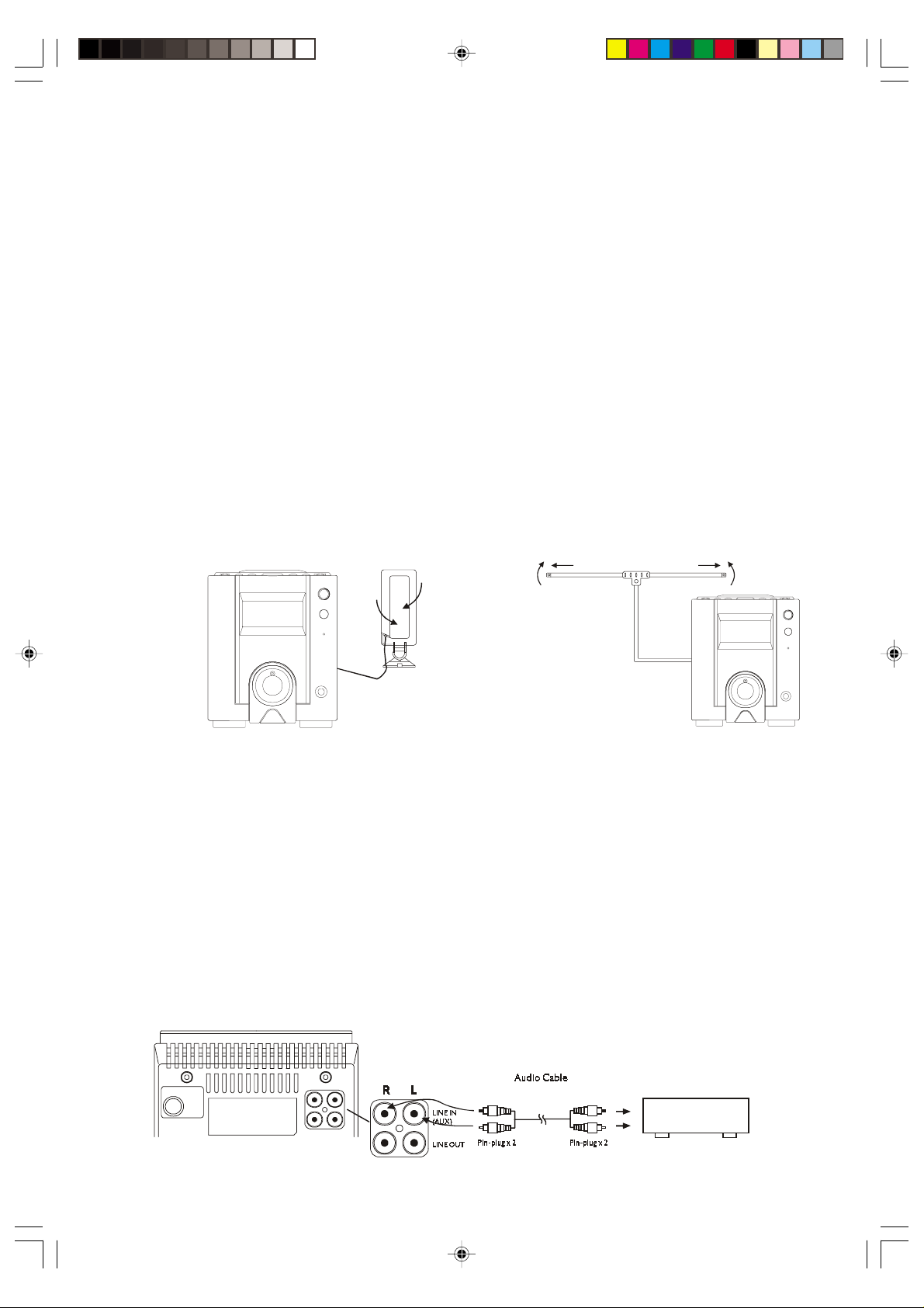
ANTENNA CONNECTION
The AM and FM antennas connect to the AM and FM terminals on the system’s back panel. They
must be hooked up in order to receive clear reception.
AM LOOP ANTENNA AND FM T-TYPE ANTENNA
Your system comes with an AM loop antenna with black wires and an FM T-type dipole antenna.
Connect the antennae to their respective terminals on the back of the unit the same way as the wire
connections from the speakers to the unit. Locate the bare ends of the wires, open the tab of the
terminal, insert the bare end of the wire and close the tab. Repeat for the other wires. After connecting
the antennas, extend them to their full length and adjust their positioning for better radio reception.
AM FM
CONNECTING AUXILIARY EQUIPMENT
This system includes auxiliary input and output jacks which allow you to connect a wide range of
external components to expand the capability of the system.
LINE IN (AUX)
Use the AUX IN jacks on the back of the unit to connect an auxiliary component, such as a cassette
deck, VCR, TV, camcorder or other compatible device. To connect an auxiliary component, connect
the left and right audio output jacks from the component to the left (L) and right (R) input jacks on
the back of the unit.
Note: Connection cables are not included.
(Not included)
External Audio Source
4
Page 6
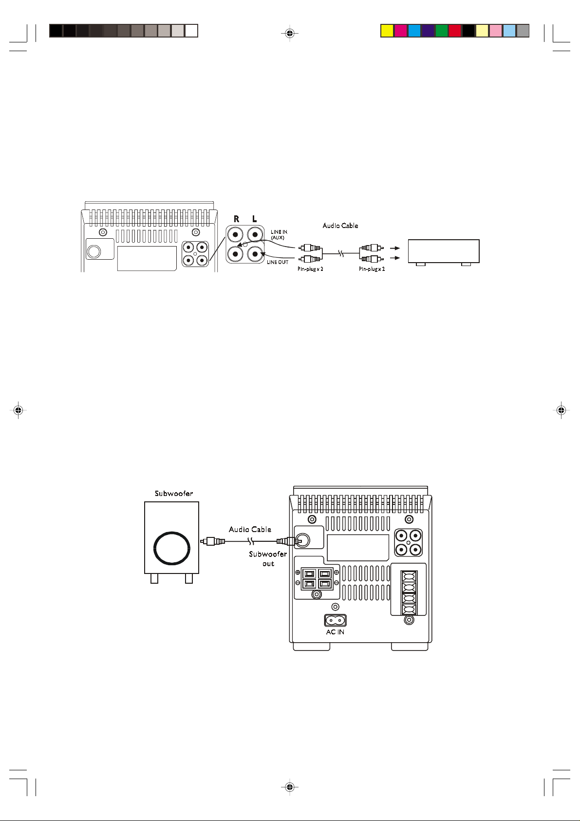
LINE OUT
g
To record from the Radio or CD player in this unit to an external recording device, connect the LINE
OUT jacks of this unit to the audio input, LINE INPUT, or RECORDING (REC) input jacks of the
external recording device, such as a cassette recorder or mini disc recorder. Be sure to refer to the
instructions for the external recording device, as well.
(Not included)
External Re co rd in
Device
SUBWOOFER (SUB) OUT
This jack allows you to connect a powered/active subwoofer speaker (not included) to this system
for increased bass response.
Note: The subwoofer must be the powered/active type with its own amplifier and its own AC power
cord. You cannot connect a passive subwoofer to the subwoofer output jack on this unit.
Connect the subwoofer out jack of this unit to the line in the jack of your subwoofer. The connection
cable is not included Be sure to refer to the instruction manual of your subwoofer, as well.
5
Page 7
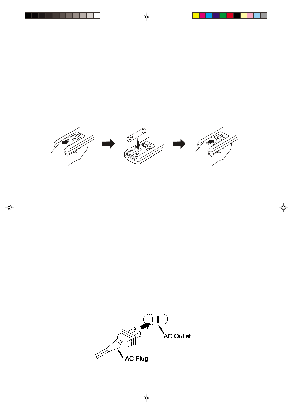
INSTALLING THE REMOTE CONTROL BATTERIES
1. Open the battery compartment cover of the remote control unit by sliding the cover downward,
as shown.
2. Insert two (2) ‘AA’ sized batteries, not included, into the battery compartment, following the
diagram inside the compartment. If the batteries are inserted incorrectly, the remote control
will not work.
3. Replace the battery compartment cover.
Note: Always use alkaline batteries for longest life and best performance.
CONNECTING THE POWER CORD
After you have connected the speakers, the AM and FM antennas and any external audio sources,
you are now ready to connect the unit to your AC power supply.
Unwind the AC cord to its full length and insert the smaller end into the AC socket on the back panel
of the main unit. Note that the AC socket and the small end of the AC cord have one rounded end
and one flat end. The cord can only fit into the AC socket one way. Do not try to force the plug into
the AC socket. If it does not enter the socket easily, turn the plug over and reinsert. Make sure that
the plug is inserted into the socket as far as it will go. A loose connection can result in intermittent
operation or a loss of power to the system.
Connect the AC plug to your 120V AC 60HZ polarized outlet. This unit has a polarized AC plug with
one blade wider than the other. This a safety feature for your protection. If the plug will not fit into
your outlet, do not try to defeat this safety feature by filing the wider blade to make it fit into your
outlet. If this plug does not fit your outlet, you probably have an outdated, non-polarized AC outlet.
You should have your outlet changed by a qualified, licensed electrician.
6
Page 8
CONTROLS AND THEIR FUNCTIONS
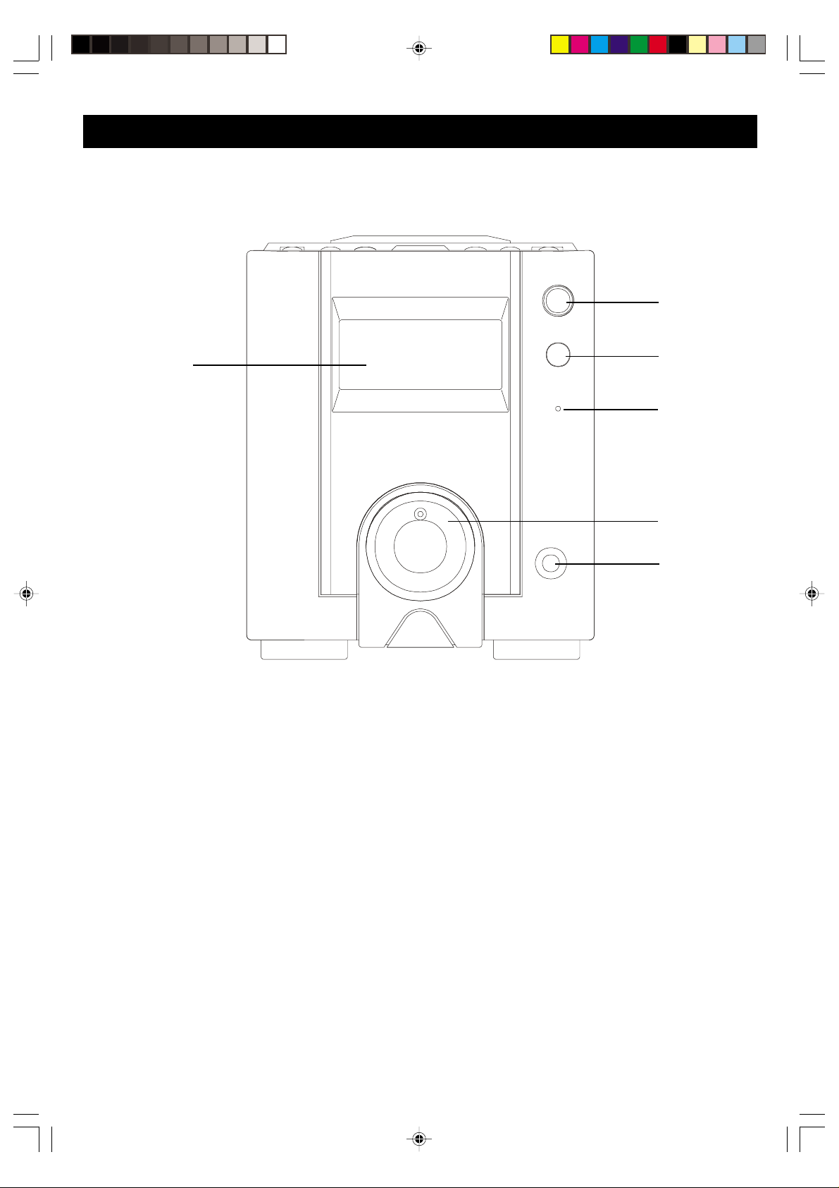
FRONT PANEL
3
1
1. MAIN DISPLAY
Displays CD, Radio and Clock/Timer
information.
4
5
2
6
5. STANDBY (INDICATOR)
This indicator lights up when the unit is in
standby.
2. VOLUME CONTROL
Rotate to increase or decrease the volume.
3. POWER
Press this button to turn the unit on and off.
4. REMOTE SENSOR
Senses infra-red signals from the remote
control.
6. PHONES (JACK)
You can plug a headphone set (not included)
into this jack for private listening. The speakers
will shut off automatically when headphones
are in use.
7
Page 9
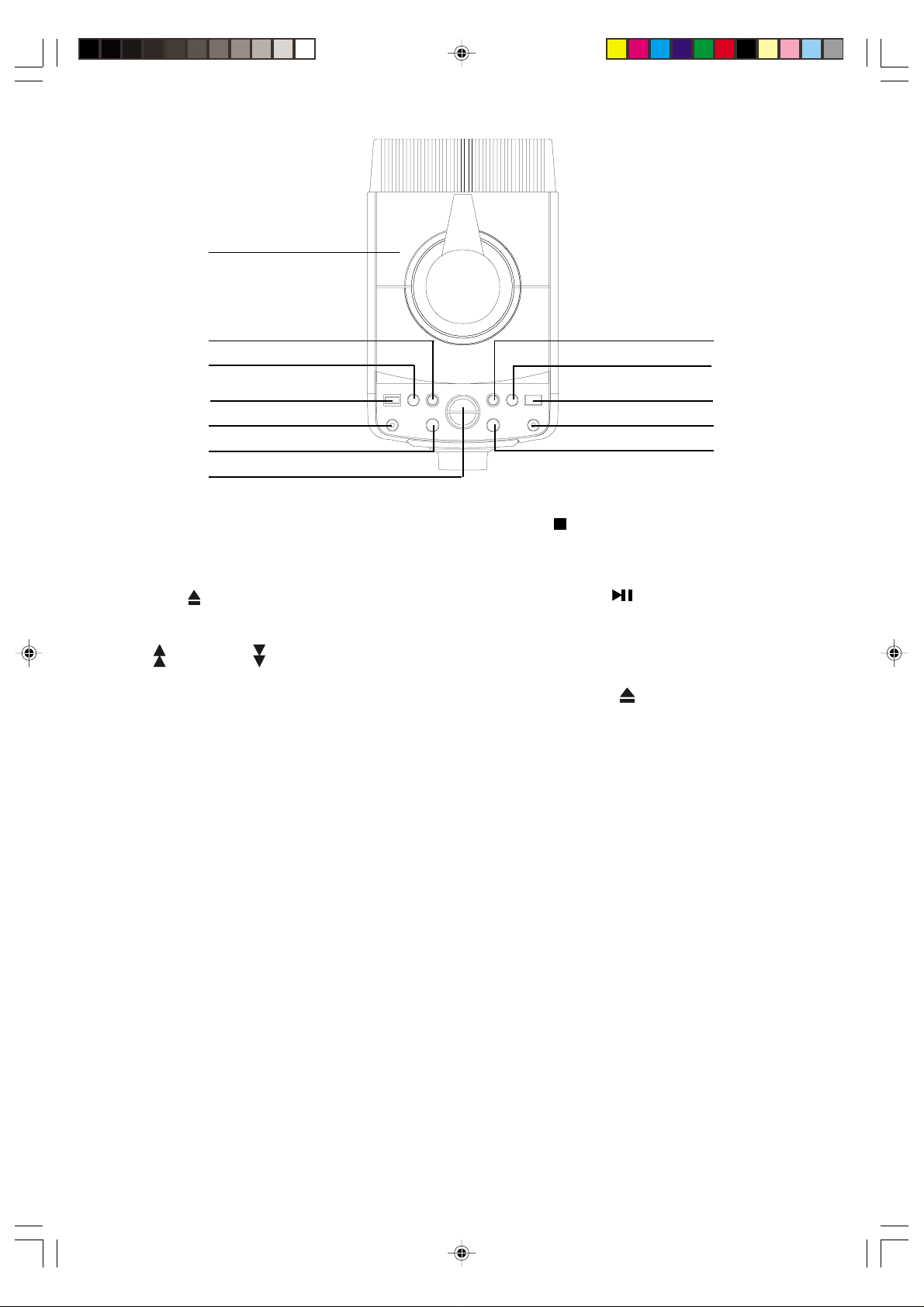
TOP PANEL
7
9
10
11
12
13
8
7. CD COMP ARTMENT DOOR
This door is motorized. Do not attempt to
open or close manually. Use the OPEN/
CLOSE
8. UP
In Radio Mode: Press to tune up or down to
find a station
In CD Mode: Press to skip tracks or start
High-Speed Music Search
In Clock Setting Mode: Press to adjust the
Time display.
9. TAPE/AUX
Press to select the device connected to the
auxiliary In/Out jacks.
10.SLEEP
Press to start Sleep-to-Music Timer operation.
button on the top panel.
/ DOWN BUTTONS
18
17
16
15
14
13.STOP
Press this button to stop CD playback.
14. PLAY/PAUSE
Press to begin CD playback and to pause
during playback.
15. OPEN/CLOSE
Press this button to open or close the
motorized CD door.
16. TIMER/SNOOZE
Press Timer button to enter the Timer On/
Off setting mode, to activate or deactivate
the Timer and to activate the Snooze feature.
17. CLOCK
Press to enter Clock setting mode or to switch
between Time and CD/Radio displays.
11. X-BASS
Press to switch the X-BASS feature ‘ON’ or
‘OFF’.
12. PRESET EQ
Press to adjust the sound for different types
of music, such as Pops, Rock, Classic, Jazz,
or Flat (EQ OFF).
18. TUNER/BAND
Press to select Tuner mode. Press again to
switch between AM and FM bands.
8
Page 10
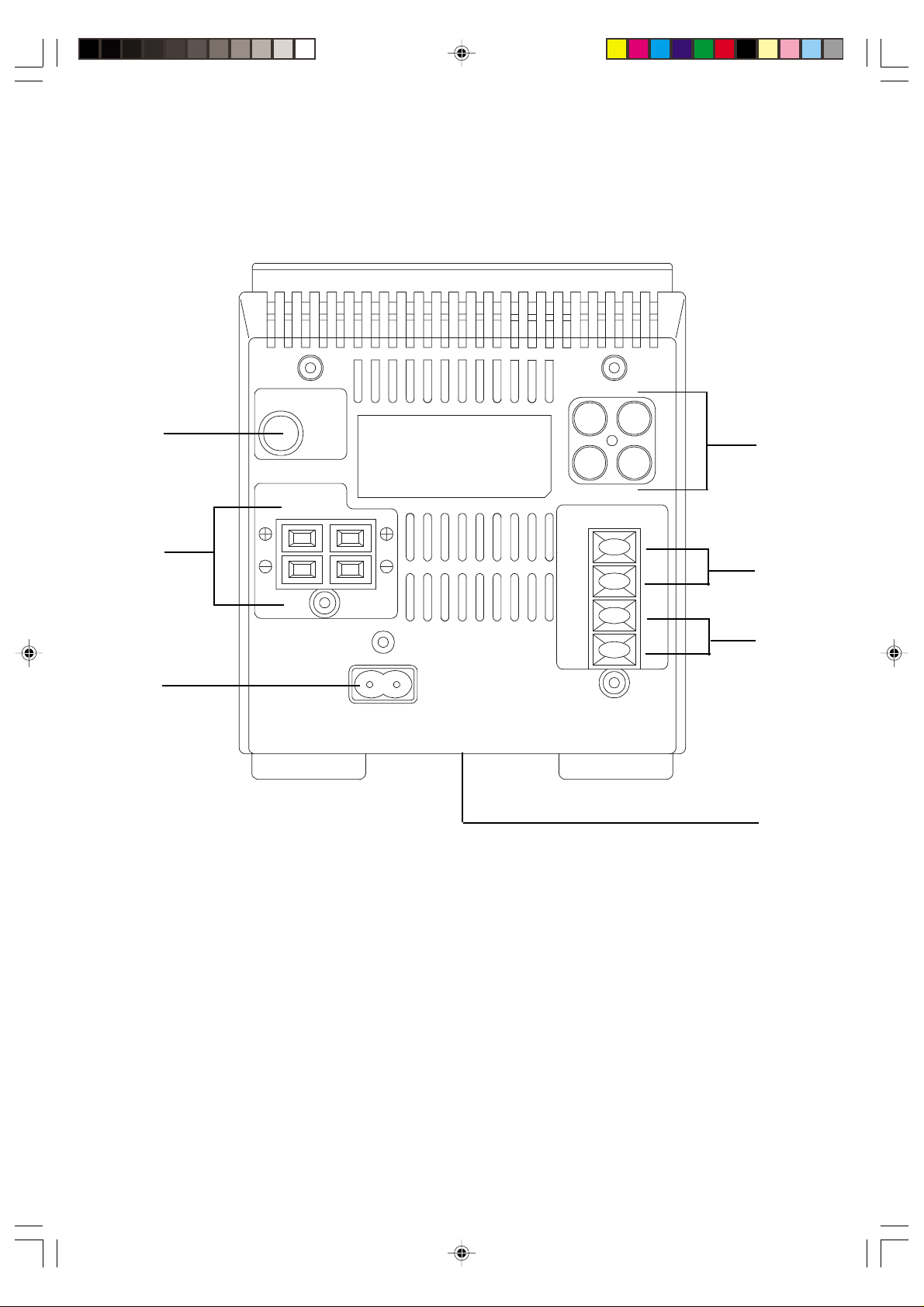
REAR PANEL
19
20
21
22
23
24
25
19. SUBWOOFER OUT Jack
For connection of an external powered
(active) subwoofer, not included.
20. SPEAKERS (TERMINALS).
21. AC IN (POWER SUPPLY).
22. LINE IN (AUX)/LINE OUT Jacks.
For connection of an external audio source
or recording device.
ANTENNA (TERMINALS)
23.
FM Ext: Connect the external FM antenna
to these terminals.
24.
AM Ext: Connect the external AM loop
antenna to these terminals.
25. RESET Button (Bottom of unit.)
“Refer to page 27 for further information.”
9
Page 11

GENERAL INDICATORS
1
9
AM PM
2
8
CD INDICATORS
5
12
3
DISPLAY INDICATORS
5
4
6
4
6
7
3
7
8
9
1. TIMER mode indicator.
2. Timer indicator (ON/OFF).
3. Bass indicator (X-BASS).
4. CLOCK indicator.
5. SLEEP indicator.
6. SNOOZE indicator.
7. Time display.
8. Preset EQ mode indicator
(POPS, ROCK, CLASSIC,
JAZZ, FLAT).
9. AM/PM indicators.
1. Playback indicator.
2. Pause indicator.
3. Function/Track number display.
4. Play time display.
5. Program mode indicator.
(MEMORY).
6. RANDOM play indicator.
7. REPEAT play indicator.
8. OVER indicator.
9. CD track index.
TUNER INDICATORS
3
4
1
5
2
2. Radio Frequency display,
channel space mode display.
3. MONO indicator.
4. STEREO indicator.
5. Preset memory indicator.
10
1. Band indicators.
Page 12

OPERATING INSTRUCTIONS
NOTE: INSTRUCTIONS FOR “USING THE REMOTE CONTROL” BEGIN ON PAGE 16.
SETTING THE CLOCK
When the system is connected to AC power for the first
time, the standby LED indicator on the front panel comes
on and the main display begins flashing “12:00 AM”. This is
your indication that the time on the display is incorrect and
needs to be set. To set the clock, proceed as follows:
1. Press and hold the CLOCK button on the top panel for
at least one second.
2. Adjust the hours on the display by pressing the UP
button. Each time you press the UP button, the display
CLOCK
will advance by one hour. If you hold the UP
the hours will continue to advance.
Note: Make sure you are setting the time to the correct hour
(AM or PM) by confirming that the correct AM or PM
indicator appears in the display.
3. Adjust the minutes by pressing the DOWN
Each time you press the DOWN
will advance by one minute. If you hold the DOWN
button, the minutes will continue to advance.
4. When the correct time appears on the display, press the
CLOCK button once more. The time display will stop
flashing and the clock will begin to run normally from
that point.
The time will always appear on the display when the power is switched off. To see the time while
you are listening to Radio or playing a CD, simply press the CLOCK button once. The display will
change from either Radio frequency or CD display to Clock display. To change back to Radio
frequency or CD display, press the CLOCK button once more.
button, the display
button,
button.
Note: If the unit is disconnected from the AC power supply or the AC power supply is interrupted for
any reason, the clock timer settings will be lost and it will be necessary to reset the clock
when power is restored.
11
Page 13

AUTO POWER ON
This system includes Auto Power On circuitry. Once the system is connected to your household
outlet you can turn the system ‘On’ by simply pressing the appropriate button for the function you
would like to hear. It is not necessary to press the Power button first and then press a function
button. For example, to turn the system ‘On’ to the tuner function you may simply press the Tuner/
Band button directly.
LISTENING TO THE RADIO
Note: Make sure that both the external AM loop antenna and the FM dipole antenna have been
properly connected to the antenna terminals on the back panel of this system. Refer to the instructions
on page 9 if necessary.
1. Press the Tuner/Band button to turn the system ‘On’ to the radio function. The Standby indicator
goes off, the main display turns on and displays an AM or FM radio frequency.
2. To select a different band if necessary, press the Tuner/Band button again. Each time you press
the Tuner/Band button while in the Tuner mode, the tuner switches between the AM and FM
bands.
3. Use the Up
• Manual Tuning – press the Up
appears in the display.
• Automatic Tuning – hold the Up
release the button. The tuner will search up or down for the next strong station and stop on that
station. Repeat this step until the frequency of your desired station appears in the display.
4. Adjust the Volume control to the desired level.
5. Adjust the tone quality by pressing the Preset EQ button on the top panel to select the appropriate
setting. The Preset EQ settings are: POPS>ROCK>CLASSIC>JAZZ>FLA T (EQ ‘Off’). The selected
setting appears in the display.
Note: These settings are a matter of personal taste.
For example, if you find that you enjoy all types of music with the preset EQ set to ‘POPS’,
feel free to leave the EQ in the ‘POPS’ setting all the time.
/Down buttons on the top panel to tune to your desired station as follows:
or Down button repeatedly until the frequency of your station
or Down button until the display begins to scan and then
12
Page 14

6. To enhance the bass response, especially at lower volume levels, press the X-BASS button on
the top panel. The X-BASS indicator appears in the display to confirm that the X-BASS circuit is
‘On’.
Note: If you are listening to loud rock music with heavy bass, the EQ set to ‘ROCK’, and the X-BASS
circuit ‘On’, you might experience some distortion from the speakers. If this occurs, lower the
volume or switch the X-BASS circuit ‘Off’.
7. When you are finished listening, press the Power button to turn the system ‘Off’. The main
display changes from radio frequency to time, the display lighting goes ‘Off’ and the standby
indicator comes ‘On’ again.
Presetting Your Favorite Stations
This system allows you to preset up to 20 of your favorite stations (any combination of FM and AM)
in the tuner memory for easy, one-touch recall at any time. The instructions for presetting stations
will be found in the Remote Control Operation section later in this manual.
SYSTEM MEMORY
The system memory remembers all of the settings you selected before the power was switched
‘Off’, and automatically returns to those settings (Function, Band, Station, Volume, EQ, and
X-BASS) when the system is switched ‘On’ again. Note: If the system is unplugged or the AC power
is interrupted, the system memory will be erased.
AUXILIARY SOURCE SELECTION
To listen to an auxiliary source which is connected to the Auxiliary Input jacks on the back panel of
this unit:
1. Press the Tape/Aux button on the top panel. The standby indicator goes ‘Off’, the main display
comes ‘On’, and AUX appears in the display.
2. Operate your auxiliary device according to its own instructions.
3. Adjust the Volume, Preset EQ, and X-BASS controls on this system to your desired settings.
4. When you are finished listening press the Power button to shut the system ‘Off’. Also shut off the
power on the auxiliary device as well.
T o record from the tuner or CD player in this system to an external recording device which is connected
to the Auxiliary Output jacks on the back panel of this unit, operate the tuner or CD player of this unit
as you would normally. Operate your external recording device according to its own instructions. If
your external recording device has recording volume level controls and recording level meters, be
sure to adjust them properly to prevent saturation and distorted recordings.
13
Page 15

PLAYING COMPACT DISCS
Normal Playback
1. Press the Power button to turn the system ‘On’.
2. Press the Open/Close
as the door opens.
3. Place your CD on the center spindle with the printed label side facing ‘up’.
4. Press the Open/Close
door by hand.) The display will show ‘CLOSE’ as the door closes. If the system was in the CD
mode the player will read the disc and display the total number of tracks and the total playing
time of the disc. If the system was in a different mode (Tuner or Tape/Aux) the display will show
the last mode selected.
5. Press the Play/Pause
the total number of tracks and total playing time, and then playback will begin on Track 1 and the
display will show the elapsed playing time.
6. After the last track has played the player stops and the display again shows the total number of
tracks and total playing time of the disc. If you are finished listening, press the Open/Close
button to open the door and remove your disc. Press Open/Close again to close the door,
then press the Power button to shut the system ‘Off’.
Pause Function
button to open the motorized CD door. The display will show ‘OPEN’
button again to close the motorized CD door. (Do not try to close the
button to begin playback. The display will briefly show ‘Cd’, then display
To pause during CD playback, press the Play/Pause
appears in the display and the time display flashes. The CD continues to spin but no sound is
heard. To release pause and resume playback, press the Play/Pause
pause
Stop Function
To stop playback before the disc ends, press the Stop
display again shows the total number of tracks and the total playing time on the disc.
Skip Track and High Speed Music Search Functions
Note: The Up and Down buttons are used for the Skip and Search functions.
To skip to a different track during playback press the Up
the desired track number appears on the display. Playback will begin on the track you selected.
indicator disappears and playback resumes at exactly the same point on the disc.
button again. The Pause indicator
button once more. The
button at any time. The disc stops and the
or Down button on the top panel until
14
Page 16

To start playback on a specific track, insert your disc in the player and wait until the display shows
the total tracks and playing time. Press the Up
appears on the display, and then press the Play/Pause
you selected.
To search rapidly forward or backward during playback to repeat or bypass a specific passage,
depress and hold the Up
as long as the Up
or Down button is released.
Notes:
1. The search function only operates in the playback or pause modes.
2. The volume is automatically reduced during high-speed music search operation.
Random, Repeat, and Programmed Playback
These three CD functions can only be operated with the handheld remote control. Please refer to
the Remote Control Operation instructions later in this manual.
or Down button is depressed. Normal playback will resume when the Up
or Down button. The player will search rapidly forward or backward
or Down button until the desired track number
button. Playback will begin on the track
15
Page 17

REMOTE CONTROL KEYS AND THEIR FUNCTIONS
20
19
1
18
16
3
2
4
6
5
8
7
1. Number Buttons (0-9, 10+)
Tuner - Selects Preset Stations.
CD - Direct track Selection.
2. CD RANDOM Button.
3. CD REPEAT Button.
4. Up
Tuner - Selects Desired Station.
CD - Skip Track and High-Speed Search.
Clock - Adjusts Time Display.
Timer - Adjusts Timer Settings.
5. CLOCK Button.
6. TIMER/SNOOZE Button.
7. PRESET EQ Button.
8. X-BASS Button.
/ , Down / Buttons.
17
15
14
13
12
11
10
9
9. VOLUME Up (+) / Down (-) Buttons.
10. Display DIMMER Button.
11. MUTE Button.
12. STEREO Button - Stereo (Auto)/Mono.
13. TUNER/BAND button.
14. CD Stop
15. CD Play/Pause
16. PROGRAM Button.
Tuner - Enters Stations in Preset Memories.
CD - Enters Tracks in CD Memory.
17. AUTO PRESET Button.
18. TAPE/AUX Button.
19. SLEEP Timer Button.
20. POWER (Standby) Button.
Button.
Button.
16
Page 18

USING THE REMOTE CONTROL
GENERAL CONTROLS
POWER
Press once to turn the system ‘ON’; press again to turn the system ‘OFF’.
Note:The ST ANDBY indicator will turn of f when the system is turned on; it will turn on when the system
is turned off.
0 – 9 BUTTONS
Tuner - Press to select a preset station.
CD - Press to select a specific CD Track.
10+ BUTTON
Press in conjunction with other number keys to directly access CD tracks or preset stations with numbers
higher than 9.
TUNER/BAND
Press once to activate the Tuner mode. Press again to switch between AM or FM bands.
AUTO PRESET
Press to automatically enter the 20 strongest stations (10 FM/ 10 AM) into the preset tuner memories.
AUX/TAPE
Press to select an audio source connected to the LINE IN (AUX) terminal.
CD PLAY/PAUSE
Press once to activate CD mode. Press again to begin CD playback. During playback, press to enter/
exit the pause mode.
REPEAT
Press once to repeat a single track or programmed play sequence; press again to repeat all tracks on
the disc.
RANDOM
Press to begin random playback. Press again to resume normal playback.
STOP
Press to stop playback.
SKIP/SEARCH
Press once to skip through tracks. Press and hold to search through current track.
/
17
Page 19

TUNING
Tuning Up
VOLUME (+ / -)
Use to adjust the level of sound output; + to increase the volume, - to lower the volume. The volume
knob on the front panel moves in response to these controls.
MUTE
Press once to shut off the sound from the speakers. Press again to restore the sound. The mute
indicator in the volume control flashes when the Mute function is activated.
X-BASS
Press to activate the X-BASS circuit and provide deeper bass response.
Press again to cancel X-BASS.
PRESET EQ
Press to select among Pops, Rock, Classic, Jazz or Flat (EQ Off) settings. The tone quality changes
according to the setting you select.
DIMMER
When the power is on, pressing this button dims the display. When the button is pressed again, the
display returns to its normal brightness.
/ Down – Press to start manual or auto tuning.
SLEEP
Press to activate Sleep Timer mode.
CD OPERATIONS USING THE REMOTE CONTROL
The following CD features and functions are operated by the Remote Control only.
DIRECT ACCESS PLAY
Pressing any of the track number buttons will start play from the beginning of the designated track
without having to press the Play/Pause
play.
1. Press the Stop
2. Enter the required track using the track number buttons:
• To select track numbers 1 through 9, press the track number button corresponding to the track
number.
• To select track number 10 or higher, first press the “10+” key on the remote control. “TRACK”
appears on the display. Then press the 2 keys corresponding to the desired track number.
(For example: 15=1 and 5)
• To skip to another track during playback, press the number of the desired track. The display
shows the selected track number and playback starts from the beginning of the selected track.
button to stop playback, if necessary.
button. This function cannot be used during programmed
18
Page 20

REPEAT PLAYBACK
Single track repeat:
Select the track you want to repeat and press the Repeat button once. “REPEAT 1” appears in the
display. Press the Play/Pause button, if necessary. The selected track will be repeated continuously.
All Tracks Repeat :
Press the Repeat button twice, or until “REPEA T ALL” appears in the display. Press the Play/Pause
button, if necessary. The entire disc will be repeated continuously.
To cancel Repeat Playback, press the Repeat button until the REPEAT indicator disappears.
PROGRAMMED PLA YBACK
Up to 20 tracks can be programmed to be played in any desired order.
Note: Programming is only possible when the CD is stopped. If the CD is playing, press the Stop
button first.
1. Press the Program button on remote handset to enter the programming mode. The MEMORY
indicator begins flashing and the display appears as follows:
Program memory # 1.
2. Use the number keys or the
Example: Track # 8. The display appears as follows:
3. Press the Program button to enter the selected track into the Program Memory.
The display appears as follows:
/ keys to select the first track you wish to program.
Program memory # 2.
4. Repeat Steps 2 and 3 to enter up to 20 tracks in the Program Memory.
19
Page 21

5. Press the Play/Pause button to begin programmed Playback. The MEMORY indicator stops
flashing and playback begins on the first track you selected. The CD index display will show which
tracks have been programmed and the current track indicator flashes.
If you press the Skip/Search
the next/previous track in the program memory.
When the last programmed track has played, the CD stops and the display shows the total tracks
and playing time of the disc. But the MEMORY indicator remains on and the program remains in the
memory. If you press the Play/Pause
To cancel the program from the Memory:
After the disc has stopped – press Stop
When the disc is playing – press Stop
display.
The program will also be cancelled from the Memory when the CD door is opened.
/ buttons during programmed playback, the player will skip to
button, the program will begin again.
button once.
button twice. The MEMORY indicator disappears from the
RANDOM PLAYBACK
Press the Random button to play all the tracks on a disc in random order. The RANDOM indicator
appears in the display. Press the Play/Pause
has played once, the player stops.
To cancel random playback, press the Random button until the RANDOM indicator disappears, or open
the CD door.
button to begin playback if necessary. After each track
TUNER OPERATIONS USING THE REMOTE CONTROL
The following tuner features and functions can be operated by the remote control:
MANUAL TUNING
Each time you press either the tuning Up or Down buttons on the remote control, the tuner
display moves up and down by one step (200 kHz). Repeatedly press either the tuning Up
Down
main display.
Use the manual tuning method when you want to tune in stations that are not strong enough to be
tuned by the automatic tuning method. The manual tuning method will allow you to tune to any
frequency on the AM and FM bands.
AUTOMATIC TUNING
Depress and hold either the tuning Up
display begins to scan up or down and then release the buttons. The tuner will automatically stop
on the next receivable station. Repeat this operation until the display indicates the exact frequency
of your desired station.
buttons on the remote control until the exact frequency of your desired station appears on
or tuning Down buttons on the remote control until the
or
20
Page 22

FM MODE SELECTOR (STEREO, AUTO/MONO BUTTON)
This control allows you to select between FM mono and FM stereo reception.
This system will automatically select the FM stereo mode when you tune to the FM band. When an
FM station is broadcasting in stereo, the STEREO indicator will appear in the display.
If you are listening a weak or distant FM station and the reception is noisy or intermittent, you may
be able to improve the reception by pressing the Stereo Auto/Mono button to select the mono
reception mode. The MONO indicator will appear in the display to confirm you are in the mono
reception mode. This should provide some improvement in reception on weak or distant stations.
As soon as you tune to a new FM station, the tuner will automatically switch back to the stereo
reception mode.
PRESETTING THE TUNER MEMORY
Y ou can store up to a maximum of 20 FM and AM stations in any combination in the tuner memories.
To store a station in memory, proceed as follows:
1. Press the Tuner/Band button to select the tuner mode.
2. Press the Tuner/Band button again to select between the AM or FM bands, if necessary.
3. Tune to the first station you wish to store in memory by
either the automatic or manual tuning methods.
(Example: FM 93.9 MHZ)
4. When the frequency of the desired station appears on
the display, press the Program button on the remote
control handset. The MEMORY indicator will begin flashing
in the display.
5. Press the Number 1 button on the remote handset to
select preset memory location 1.
6. Press the Program button again. This will enter your
desired station into preset Memory 1. Preset 1 will appear
in the display before the radio frequency and the
MEMORY indicator will stop flashing.
7. Repeat Steps 2 through 6, selecting a different preset number each time until you have stored
up to 20 AM/FM stations in any combination in the tuner memory.
Note: To select memory numbers above 9, you must press three keys as follows:
To Select Memory 10: Press the “10+”, “1”, and “0” keys in order.
To Select Memory 11: Press the “10+”, “1”, and “1” keys in order.
To Select Memory 12: Press the “10+”, “1”, and “2” keys in order, and so on.
21
Page 23

IMPORTANT:
After pressing the Program button for the first time, you must select the preset Memory number and
press the Program button again to store the station within ten seconds while the MEMORY indicator
is flashing in the display. If the MEMORY indicator stops flashing before you press the Program
button for the second time, the station will not be stored in the Memory. If this should occur, press
the Program button again so that the MEMORY indicator is flashing, then press your desired memory
location button and press the Program button again.
TO CHANGE A PRESET STATION
If you wish to change one of your previously memorized stations, simply enter a new station into the
memory location that you wish to change. When the new station is entered into a memory, the
station previously stored in that memory will be erased.
SELECTING A PRESET STATION
After you have stored up to 20 AM and FM stations in the preset tuner memories, you can select
any of the memorized stations quickly and easily as follows:
1. Press the Tuner/Band button to select the Tuner mode.
2. Press the Tuner/Band button again to select the desired band, if necessary.
3. Press the number key that corresponds to the desired station.
4. Press the 1 through 9 keys to select preset memories numbers 1 through 9.
5. To select preset memory 10, press the “10+”, “1” and “0” keys in order.
6. To select memory above 10, you must press three keys in sequence, the “10+” key, and then the
two keys which correspond to the memory number you wish to select.
For example: To select preset number 15, press “10+”, “1”, and “5” keys in order.
22
Page 24

AUTO PRESET TUNING
GENERAL COMMENTS ABOUT THE AUTO PRESET FEATURE
If you live in a major metropolitan area or in close proximity to a large city with many AM and FM
stations available, it is not recommended to use the Auto/Preset feature. This feature will cause the
Tuner to memorize the first 10 FM and AM stations it encounters and these will probably not be the
stations that you want to store in the Tuner memory.
However, if you live in a rural area with fewer AM and FM stations available, you can use the auto
preset feature to automatically enter 10 AM and 10 FM stations into the Tuner memory. Again, the
Tuner will memorize the first 10 FM and AM stations that are receivable in your area.
USING THE AUTO PRESET FEATURE
1. Press the Tuner/Band button on the main unit or remote control to select the tuner function,
Press again to change the Band if necessary.
2. Press the Auto Preset button on the remote control handset for at least two seconds. The Tuner
will begin searching the band for strong signals and it will automatically enter into the memories
the first 10 strong signals it encounters.
3. After the Tuner stops scanning, press the Tuner Band button once more to change bands and
then depress the Auto Preset button again for at least two seconds to automatically preset 10
stations on the remaining band.
SELECTING PRESET STATIONS
Press the appropriate number key on the remote control handset to select the desired preset Memory
number. Remember that to select preset memories numbered 10 through 20, you must press three
keys, the “10+” key, and the two keys which correspond to the desired track number.
For example: To select track number 15, press the “10+”, “1” and “5” keys in order.
23
Page 25

SETTING THE TIMER
This system includes a built-in timer that will automatically switch the power ‘On’ at whatever time
you select, play for the length of time you desire and then shut itself ‘Off’ automatically.
SETTING “On” TIME
Note: In order for the timer to operate correctly, the clock must also be set correctly. If you have not
yet set the clock, please refer to the instructions for setting the clock on Page 11 and set the clock
correctly before you begin setting the Timer.
You may set the Timer using either the controls on the top panel of the main unit or the keys on the
remote control handset.
1. Press the Timer/Snooze button on either the
main unit or the remote control handset to
begin setting the ‘On’ time. The TIMER
indicator appears in the display and the ON
indicator and Time display begin flashing.
2. Press the Up
adjust the display to the desired ‘On’ hour. Be sure to observe the AM/PM indicators to confirm
that you are setting the hour correctly for AM or PM.
3. Press the Down
to adjust the Time display to the desired ‘On’ minute.
4. When the desired ‘On’ time is flashing in the
display , press the Timer/Snooze button once
more. The ON indicator disappears and the
OFF indicator begins flashing in the display.
Use the Up
unit or the Hour/Minute buttons on the remote
control handset to set the display to the
desired ‘Off’ time.
5. When the desired ‘Off’ time is flashing in the display press the Timer/Snooze button on the main
unit or the remote handset once more. The OFF indicator stops flashing and the display returns
to the correct time of day. The TIMER indicator remains in the upper left-hand corner of the
display.
button on the top panel or the Hour button on the remote control handset to
button on the top panel or the Minute button on the remote control handset
/ Down buttons on the main
24
Page 26

6. At the selected ‘On’ time, the system will turn on automatically. It will play until it reaches the
‘Off’ time you selected and will then shut itself off. It will repeat this automatic on/off cycle every
day at the same time as long as the TIMER indicator appears in the display. To cancel the
automatic on/off timer, press the Timer/Snooze button on the main unit or on the remote control
until the TIMER indicator disappears from the display.
TIMER OPERATION
The Timer can be used to turn the unit ‘On’ to radio or to begin CD playback.
RADIO OPERATION BY TIMER
• After setting the Timer ‘On’ and Timer ‘Off’ times, as described above, press the Tuner/Band
button to turn the unit on to the Tuner mode. Tune to the station you wish to hear when the
system turns ‘On’ and adjust the volume, preset EQ, and X-BASS controls as desired.
• Press the power button to switch the unit back to the standby mode. The STANDBY indicator
comes on. At the pre-selected ‘On’ time, the system will turn on to the radio station you selected.
It will play until it reaches the selected ‘Off’ time and then shut off automatically.
CD OPERATION BY TIMER
• After setting the Timer ‘On’ and Timer ‘Off’, as described above, press the Power button to turn
the system on, insert a CD in the CD compartment, press the Play/Pause
unit to the CD mode and begin playback.
• Adjust the volume control, preset EQ , and X-BASS controls as desired, and then press the Stop
button to stop playback.
• Press the Power button to switch the unit back to the Standby mode.
At the pre-selected ‘On’ time, the unit will turn on and begin CD playback. At the selected Timer ‘Off’
time, playback will stop automatically and the system will return to the Standby mode.
SNOOZE OPERATION
After the unit switches ‘On’ automatically in either the radio or the CD modes, you may press the
Timer/Snooze button on the main unit or the remote control to activate the snooze function. The
radio or CD will stop for approximately 5 minutes and will then switch on again automatically.
button to switch the
Note: If the Snooze button is pressed when there is less than 5 minutes remaining before the Timer
‘Off’ time, the unit will not turn on again automatically. Instead, when the Timer ‘Off’ time is reached,
the unit will enter the Standby mode.
25
Page 27

SLEEP TIMER OPERATION
This unit incorporates a sleep timer which allows you to listen to radio or CD while you fall asleep
and then the system will shut off automatically. The Sleep timer can be set for as few as 10 minutes
or for as long as 2 hours (120 minutes) before shutting off automatically.
To operate the Sleep Timer, proceed as follows:
1. Select the desired mode, Tuner or CD, and adjust the volume, preset EQ, and X-BASS controls
as desired.
2. Press the Sleep button on the main unit or on the remote control handset. The SLEEP indicator
and the number 10 (minutes) appear in the display. This indicates that the unit will turn off
automatically after 10 minutes.
3. To increase the amount of time before auto turn-off, continue pressing the Sleep button. Each
time you press the Sleep button, the amount of sleep time will increase by 10 minutes, up to a
maximum of 2 hours (120 minutes). If the Sleep button is pushed again while 120 minutes
appears on the display, it will revert back to 10 minutes.
4. After 5 seconds, the Sleep time indication disappears and the display returns to either radio
frequency or CD Track/Time display. However, the SLEEP indicator remains in the display to
confirm that the unit is in the Sleep/Timer mode.
5. After the Sleep Timer counts down to zero, the unit shuts off automatically and returns to the
Standby mode.
To shut the unit off before the Sleep Timer counts down to “00”, press the Power button to return the
unit to the Standby mode. The SLEEP indicator disappears from the display.
26
Page 28
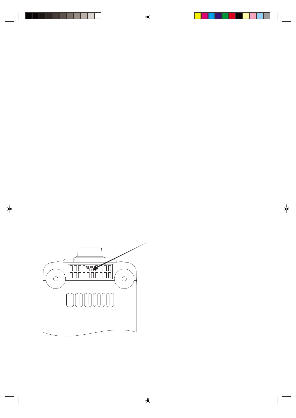
SYSTEM LOCK-UP / RESETTING THE SYSTEM COMPUTER
If the built in system computer is subjected to a sudden surge or 'spike' in the AC power supply the
computer may 'lock-up' and the unit will not respond to commands from any of the front panel
controls or the remote controller. If such a 'lock-up' occurs you must use the RESET button, located
on the inside bottom of the unit, to unlock the system computer.
Refer to the following illustration.
1.) Leave the unit connected to the AC outlet. The system computer cannot be reset if the AC
power cord is disconnected.
2.) If the power is 'On', press the POWER button to return the unit to the 'Standby' mode. The main
display goes off and the STANDBY indicator comes 'On'.
3.) Place the main unit on it's side to expose the bottom of the set.
4.) Use a wooden or plastic toothpick, or similar device (Do Not Use Any Metal Object) to press the
RESET button which is located inside the cabinet, as shown in the illustration.
Note: This procedure will clear the system computer lock-up, but it will also clear the preset tuner
memories, any CD program settings, clock and timer settings. It will be necessary to reprogram
the tuner memories, reset the clock, and reset the timer after you clear the system computer.
RESET button hole
(Press the button inside with a non-metal stick)
Bottom View
27
Page 29

CARE AND MAINTANENCE
There are no user serviceable parts inside the unit. Do not attempt any adjustments other than
those described in the manual. Refer all other problems to qualified service personnel.
COMPACT DISC CARE
• To remove a disc from its storage case, press down on the centre of the case and lift the disc
out, holding it carefully by the edges.
• Treat the disc carefully. Handle the disc only by its edges. Never allow your fingers to come in
contact with the shiny, unprinted side of the disc.
• Do not attach any tape, stickers, etc. to the disc label.
• Clean the disc periodically with a soft, lint-free, dry cloth. Never use detergents or abrasive
cleaners to clean the disc. If necessary, use a CD cleaning kit.
• If a disc skips or gets stuck on a section of the disc, it is probably dirty or damaged (scratched).
• When cleaning the disc, wipe in straight lines from the center of the disc to the outer edge of the
disc. Never wipe in circular motions.
CABINET CARE
If the cabinet becomes dusty, wipe it with a soft cloth. If the cabinet becomes smudged or dirty,
clean it with a soft, slightly dampened cloth. Never allow water or any liquid to get inside the cabinet.
Never use any abrasive cleaners or cleaning pads as these will damage the finish of your radio.
TO FIND THE LOCATION AND PHONE
NUMBER OF YOUR NEAREST SERVICE
SERVICE
CALL TOLL FREE: 1-800-695-0098
FOR ADDITIONAL SET-UP OR OPERATING ASSISTANCE
FOR CUSTOMER SERVICE,PLEASE WRITE TO:
CENTER PERMITTED TO PERFORM
WARRANTY...
PLEASE CALL:
1-800-898-9020
Emerson Radio Corp.
Consumer Affairs Dept.
1901 Diplomat Drive,
Farmers Branch, TX 75234.
28
Page 30

EMERSON RADIO CORP.
LIMITED WARRANTY
What does this warranty cover ? Any manufacturing defects in original material, including original parts and
workmanship, under normal use and conditions.
For how long? For a period of ninety (90) days from the date of original purchase in the U.S.
What will we do ? If you need service under this Warranty , and you provide us with the dated proof of purchase, we will
provide repair service at no charge for labor and parts at an authorized Depot Repair Facility, or replace the product in
our discretion.
How do you make your warranty claim ? If it becomes necessary to repair your unit, you can obtain the name and
mailing location of a Depot Repair Facility by dialing 1-800-695-0098. You should pack your unit in a well-padded
heavy corrugated box, enclose your check or money order payable to the Depot Repair Facility in the amount of $9.00 to
cover the return shipping and handling costs, and enclose a copy of your proof of purchase (warranty service will not be
provided without a dated proof of purchase). Finally, you should ship the unit prepaid via UPS or parcel post (insured).
What does your warranty not cover ? Your warranty does not cover the following :
· Damage from negligence, misuse, abuse, accident, or failure to follow operating instructions.
· Use of product in a commercial application or rentals.
· Changes or repairs by anyone other than an authorized Depot Repair Facility.
· Damage because your unit is improperly connected to the equipment of other manufacturers.
· Unit on which the serial number has been defaced, modified or removed.
· Damage to equipment not properly connected to the product.
· Cost incurred in shipping your unit to and from an authorized Depot Repair Facility.
· Ordinary adjustments which you can perform as outlined in the owner’s manual.
· Signal reception problems caused by external antenna or cable systems.
· Products purchased, used, serviced, or damaged outside of the United States.
· Damage to compact discs or cassettes.
What other limitations apply to your warranty ?
THIS WARRANTY IS NON-TRANSFERABLE AND APPLIES ONLY TO THE ORIGINAL PURCHASER AND
DOES NOT EXTEND TO SUBSEQUENT OWNERS OF THE PRODUCT. THIS WARRANTY IS VALID ONLY IN
THE UNITED STATES OF AMERICA. ANY APPLICABLE IMPLIED WARRANTIES, INCLUDING THE
WARRANTY OF MERCHANTABILITY, ARE LIMITED IN DURATION TO A PERIOD OF THE EXPRESSED
WARRANTY AS PROVIDED ABOVE BEGINNING WITH THE DATE OF ORIGINAL PURCHASE AT RETAIL
AND NO WARRANTIES, WHETHER EXPRESSED OR IMPLIED, SHALL APPLY TO THE PRODUCT
THEREAFTER. WE MAKE NO WARRANTY AS TO THE FITNESS OF THE PRODUCT FOR ANY PARTICULAR
PURPOSE OR USE.
THE EXTENT OF OUR LIABILITY UNDER THIS LIMITED WARRANTY IS THE REPAIR OR REPLACEMENT
PROVIDED ABOVE AND IN NO EVENT WILL OUR LIABILITY EXCEED THE PURCHASE PRICE PAID BY
THE PURCHASER OF THE PRODUCT . UNDER NO CIRCUMSTANCES WILL WE BE LIABLE FOR ANY LOSS,
DIRECT, INDIRECT, INCIDENTAL, SPECIAL, OR CONSEQUENTIAL DAMAGE ARISING OUT OF OR IN
CONNECTION WITH THE USE OF THIS PRODUCT.
How does state law apply to your warranty ?
THIS WARRANTY GIVES YOU SPECIFIC LEGAL RIGHTS, BUT YOU MAY ALSO HAVE OTHER RIGHTS
WHICH VARY FROM STATE TO STATE. SOME STATES DO NOT ALLOW LIMITATIONS ON IMPLIED
W ARRANTIES OR EXCLUSION OR LIMITA TION OF INCIDENT AL OR CONSEQUENTIAL DAMAGE, SO THESE
RESTRICTIONS MAY NOT APPLY TO YOU.
AU898F
29
Page 31

EMERSON
Part No.: 16-2799
010- 02
800.898.9020
Printed in China
 Loading...