

Page 1

Precision Cooling
For Business-Critical Continuity
Liebert Envirosource
User Manual - 1.5 to 10 Tons, 60Hz
™
Page 2

Page 3

TABLE OF CONTENTS
1.0 INTRODUCTION . . . . . . . . . . . . . . . . . . . . . . . . . . . . . . . . . . . . . . . . . . . . . . . . . . . . . . .1
2.0 SEQUENCE OF OPERATION . . . . . . . . . . . . . . . . . . . . . . . . . . . . . . . . . . . . . . . . . . . . . .2
3.0 S
4.0 I
YSTEM COMPONENTS . . . . . . . . . . . . . . . . . . . . . . . . . . . . . . . . . . . . . . . . . . . . . . . . . 3
NSTALLATION. . . . . . . . . . . . . . . . . . . . . . . . . . . . . . . . . . . . . . . . . . . . . . . . . . . . . . . .4
5.0 MAINTENANCE . . . . . . . . . . . . . . . . . . . . . . . . . . . . . . . . . . . . . . . . . . . . . . . . . . . . . . .5
FIGURES
Figure 1 General piping arrangement—Envirosource standby pump and cooling module with
Process Fluid Chiller 1-1/2 to 5 ton air cooled models . . . . . . . . . . . . . . . . . . . . . . . . . . . . . . . . 5
Figure 2 General piping arrangement—Envirosource standby pump and cooling module with
Process Fluid Chiller 8-10 ton air cooled models with electronic hot gas bypass . . . . . . . . . . . 6
Figure 3 Physical data. . . . . . . . . . . . . . . . . . . . . . . . . . . . . . . . . . . . . . . . . . . . . . . . . . . . . . . . . . . . . . . . . 7
Figure 4 Service clearances. . . . . . . . . . . . . . . . . . . . . . . . . . . . . . . . . . . . . . . . . . . . . . . . . . . . . . . . . . . . . 9
Figure 5 Equipment layout . . . . . . . . . . . . . . . . . . . . . . . . . . . . . . . . . . . . . . . . . . . . . . . . . . . . . . . . . . . . 10
Figure 6 Cabinet dimensions for Envirosource ENV05G and ENV10G. . . . . . . . . . . . . . . . . . . . . . . . . 11
Figure 7 Cabinet dimensions for Envirosource ENV20G . . . . . . . . . . . . . . . . . . . . . . . . . . . . . . . . . . . . 12
Figure 8 Electrical schematic . . . . . . . . . . . . . . . . . . . . . . . . . . . . . . . . . . . . . . . . . . . . . . . . . . . . . . . . . . 13
TABLES
Table 1 Model numbers for minimum application flow . . . . . . . . . . . . . . . . . . . . . . . . . . . . . . . . . . . . . . 1
Table 2 Time delay settings. . . . . . . . . . . . . . . . . . . . . . . . . . . . . . . . . . . . . . . . . . . . . . . . . . . . . . . . . . . . 2
Table 3 Connection sizes (NPT male) . . . . . . . . . . . . . . . . . . . . . . . . . . . . . . . . . . . . . . . . . . . . . . . . . . . . 8
Table 4 Electrical data, 60 Hz . . . . . . . . . . . . . . . . . . . . . . . . . . . . . . . . . . . . . . . . . . . . . . . . . . . . . . . . . . 8
Table 5 Technical data—Envirosource module, 60 Hz . . . . . . . . . . . . . . . . . . . . . . . . . . . . . . . . . . . . . . 8
i
Page 4

ii
Page 5

1.0 INTRODUCTION
The Envirosource Module is an accessory to the Process Chiller, for use on systems that circulate
water and/or glycol solutions that require an isolated loop from the emergency water source. With the
heat exchanger providing fluid separation, the Envirosource automatically switches to the emergency
water source on a high fluid temperature alarm. Additionally, the module automatically switches to
standby pump operation (with interlock to shut down the Process Chiller pump) on a loss of flow
alarm.
The Envirosource Module is available in 208/230/460V, single-phase and three-phase, 60 Hz configurations. This module is a pre-piped and wired assembly that is encased in an almond colored, powder
coated and baked cabinet. It consists of a copper brazed stainless steel heat exchanger, stainless steel
pump, copper piping, RCM4 alarm monitor, adjustable time delay relays, high temperature thermostat, cooling solenoid valve, check valve and flow switch. It also includes a manual ball valve and double-check back-flow preventer on the city water line.
The integral RCM4 alarm monitor has a local display of normal operation, standby pump and standby
cooling, “on” LED. Terminal strips are included for two optional alarms (customer supplied dry contacts) and for common alarm output (dry contacts, NC/NO/COM).
Table 1 Model numbers for minimum application flow
Model # Range (gpm)
ENV05G-_00 0.3 - 1.1
ENV10G-_00 3.7 - 13.3
ENV20G-_00 3.7 - 13.3
Introduction
The Process Chiller is modified with a bypass line to permit water to flow around the chiller’s pump
when the standby pump in the Envirosource Module is operating. This bypass line runs from the
pump suction line to the pump discharge line and includes a ball valve and check valve (see
Figures 1 and 2).
1
Page 6

2.0 SEQUENCE OF OPERATION
During normal operation, cold fluid flow from the chiller passes across the flow switch, through the
heat exchanger, through the pump bypass check valve, past the supply temperature sensor and out to
the load (see Figures 1 and 2). The standby cooling solenoid valve is closed (de-energized) and the
standby pump is off.
If the flow switch senses loss of flow, a time delay is initiated to prevent nuisance switchovers. After
the delay (see Table 2 below), the alarm panel indicates “standby pump on” and the common alarm
contacts close, while the standby pump is brought on to resume flow and the chiller pump is locked
out. This mode is locked in until the reset button is pressed.
Similarly, if the thermostat senses high fluid temperature, a time delay is initiated to prevent
nuisance switchovers. After the delay (see Table 2 below), the alarm panel indicates “standby cooling
on” and the common alarm contacts close, while the solenoid valve is energized to resume cooling.
This mode is locked in until the reset button is pressed.
Table 2 Time delay settings
Condition Default
Loss of Flow 10 0 90
High Water Temp. 180 0 480
Minimum Maximum
Sequence of Operation
Delay (seconds)
Note that during normal operation, the auto/manual switches (see Figure 8) are set to “auto”. The
switch can be set to “manual” to force switchovers to standby pump and/or standby cooling for troubleshooting or maintenance.
Note that the “remote shutdown” function (see 4.0 - Installation) prevents emergency switchover
operation regardless of the status of other controls.
2
Page 7

3.0 SYSTEM COMPONENTS
RCM4 Monitor is configured to activate an LED and an audible alarm. The common alarm output
contacts will close in response to a loss of flow or high supply fluid temperature. The silence/reset button silences the alarm. The button also resets the LEDs and alarm contacts if the unit has returned to
normal mode.
Thermostat monitors supply fluid temperature. The thermostat (switchover) setpoint is adjustable
from 40°F to 90°F (4°C to 32°C). The setpoint has a differential of 3.0° to 12.0°. The recommended setting is 3.0°.
NOTE
Some applications may require different setpoints and differentials. Consult your local Liebert
representative or the factory for assistance.
Flow Switch monitors supply flow. The flow switch setpoint is adjustable. See Table 1 for minimum
flow switch setpoint range.
Solenoid Valve is 24VAC, 2-way, pilot or direct operated, with brass body.
Manual Ball Valve is 1/4 turn, brass body for shutoff or trimming of emergency water source flow.
Back-Flow Preventer is of double-check design and is located at the emergency water source piping
connection point.
System Components
3
Page 8

4.0 INSTALLATION
Prepare the location(s) for the unit (see Figure 4). Allow adequate clearance for convenient maintenance. Anchor the unit to the floor or bolt it securely to the wall using appropriate anchors (supplied
by others).
WARNING
!
Failure to fasten unit securely to wall studs or structural members with appropriate
anchors (supplied by others) may result in product failure and personal injury.
Connect the unit piping to the chiller, load, emergency water supply and drain (or recirculator). Piping connections are labeled on the unit. Be sure to bleed all air out of the fluid system. Note that the
pressure limit of the Envirosource Module is 100 psig.
CAUTION
!
To prevent leaks within the Envirosource Module, the fluid pressure should not exceed
100 psig. For installations using an Envirosource above this rating, a pressure-reducing
valve (supplied by others) is required.
Connect unit to the required AC power source through a remote on/off switch (field supplied) as indicated on the unit nameplate. Electrical service shall conform to national and local electrical codes.
Refer to unit nameplate for full load amps (FLA), wire size amps (WSA) and overcurrent protection
device (OPD) requirements. Refer to Figure 8 when making connections.
Installation
Connect pump interlock to Process Chiller. Connect optional control wiring for remote shutdown,
remote indication of loss of flow, remote indication of high temperature and common alarm, as
required.
4
Page 9

5.0 MAINTENANCE
Periodic preventive maintenance should include a monthly manual switchover to ensure that the system operates properly.
Figure 1 General piping arrangement—Envirosource standby pump and cooling module with
Process Fluid Chiller 1-1/2 to 5 ton air cooled models
Maintenance
5
Page 10

Figure 2 General piping arrangement—Envirosource standby pump and cooling module with
Process Fluid Chiller 8-10 ton air cooled models with electronic hot gas bypass
Maintenance
6
Page 11

Figure 3 Physical data
City Water Supply
Supply from Chiller
To D r a in
Maintenance
Supply to Load
Supply from
Chiller
Heat Exchanger
Pump
ENV05G-_00 / ENV10G-_00
Supply to
Load
To Drain
City Water
Supply
Heat
Exchanger
Pump
ENV20G-_00
7
Page 12

Maintenance
Table 3 Technical data—Envirosource module, 60 Hz
Process Fluid Chiller PS018A PS024A PS036A PS048A PS060A PS096A PS120A
Model Number ENV05G ENV05G ENV10G ENV10G ENV10G ENV20G ENV20G
Circulating Fluid—Water
Flow Rate, gpm (l/s)
Pressure Drop, feet (kPa)
Emergency Fluid—Water
Flow Rate, gpm (l/s)
Pressure Drop, feet (kPa)
To prevent leaks within the Envirosource Module, the water pressure should not exceed 100 psig.
2.4
(.151)
13.6
(40.65)
3.6
(.227)
21
(62.77)
3.3
(.208)
24.9
(74.43)
4.9
(.312)
27.7
(82.80)
5.3
(.334)
11.7
(34.97)
8.0
(.502)
31.4
(93.85)
7.9
(.498)
18.6
(55.60)
11.9
(.751)
51.1
(152.74)
10.2
(.644)
30.7
(91.76)
15.3
(.965)
74.4
(222.38)
16.0
(1.009)
14.2
(42.44)
24.0
(1.51)
65.1
(194.58)
20.0
(1.262)
23.7
(70.84)
30.0
(1.89)
73.7
(220.29)
Table 4 Connection sizes (NPT male)
Model ENV05G ENV10G ENV20G
Supply from Chiller 3/4" 1" 1-1/4"
From Emergency Water Supply 1/2" 3/4" 1"
To Drain or Recirculator 1/2" 3/4" 1"
Supply to Load 3/4" 1" 1-1/4"
Table 5 Electrical data, 60 Hz
ENV05G ENV10G ENV20G
Electrical
Requirements
FLA 7.6 3.5 1.6 8.8 4.6 2.1 -- 10.6 4.8
WSA 9.9 4.4 2.0 11.0 5.8 2.6 -- 13.6 6.0
OPD 15.0 15.0 15.0 15.0 15.0 15.0 -- 15.0 15.0
*Electrical data based on standard pump selection for 40% E.G.
208/230 460 208/230 460 208/230 460
1 Ph 3 Ph 3 Ph 1 Ph 3 Ph 3 Ph 1 Ph 3 Ph 3 Ph
8
Page 13

Figure 4 Service clearances
Maintenance
Shaded areas indicate
recommended clearance
for component access
and removal.
ENV05G / ENV10G / ENV20G
9
Page 14
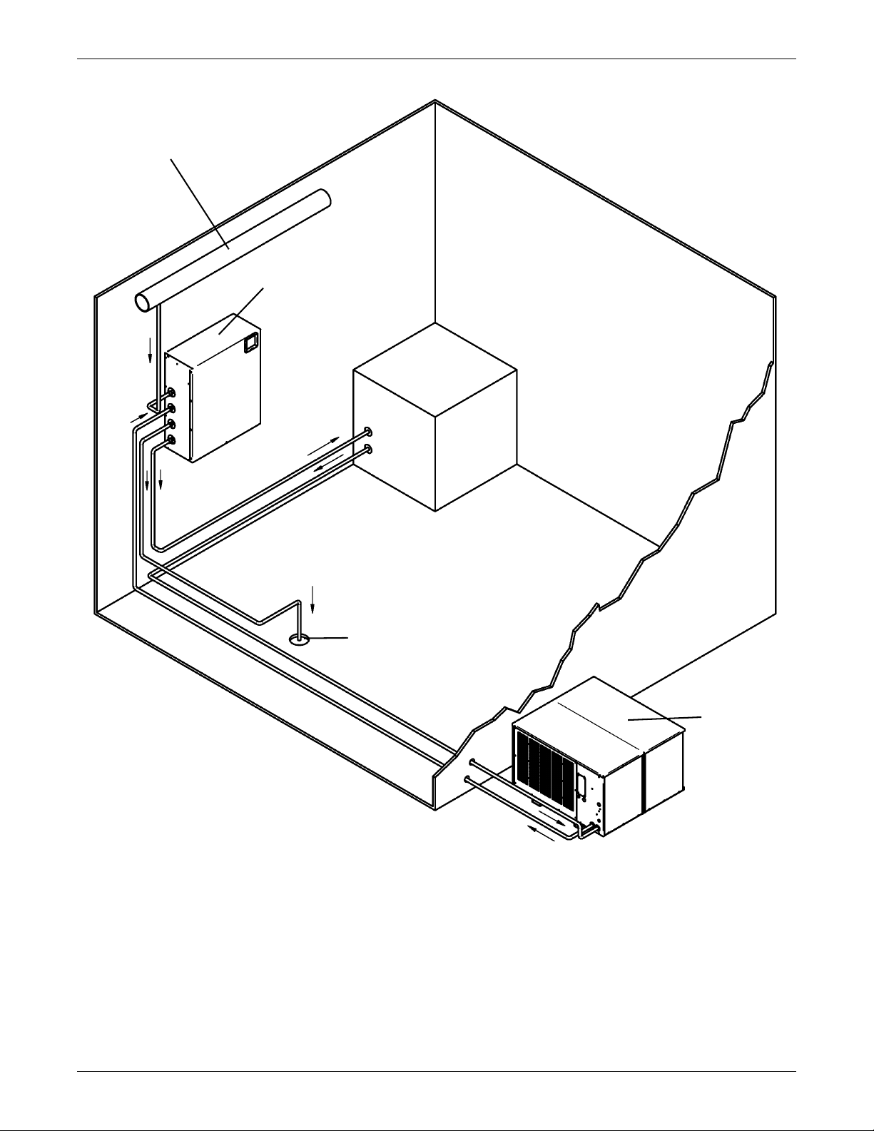
Figure 5 Equipment layout
City Water
Maintenance
Envirosource
(ENV05G or ENV10G)
Load
Outdoor (Glycol) Application
Drain
Process
Chiller
10
Page 15
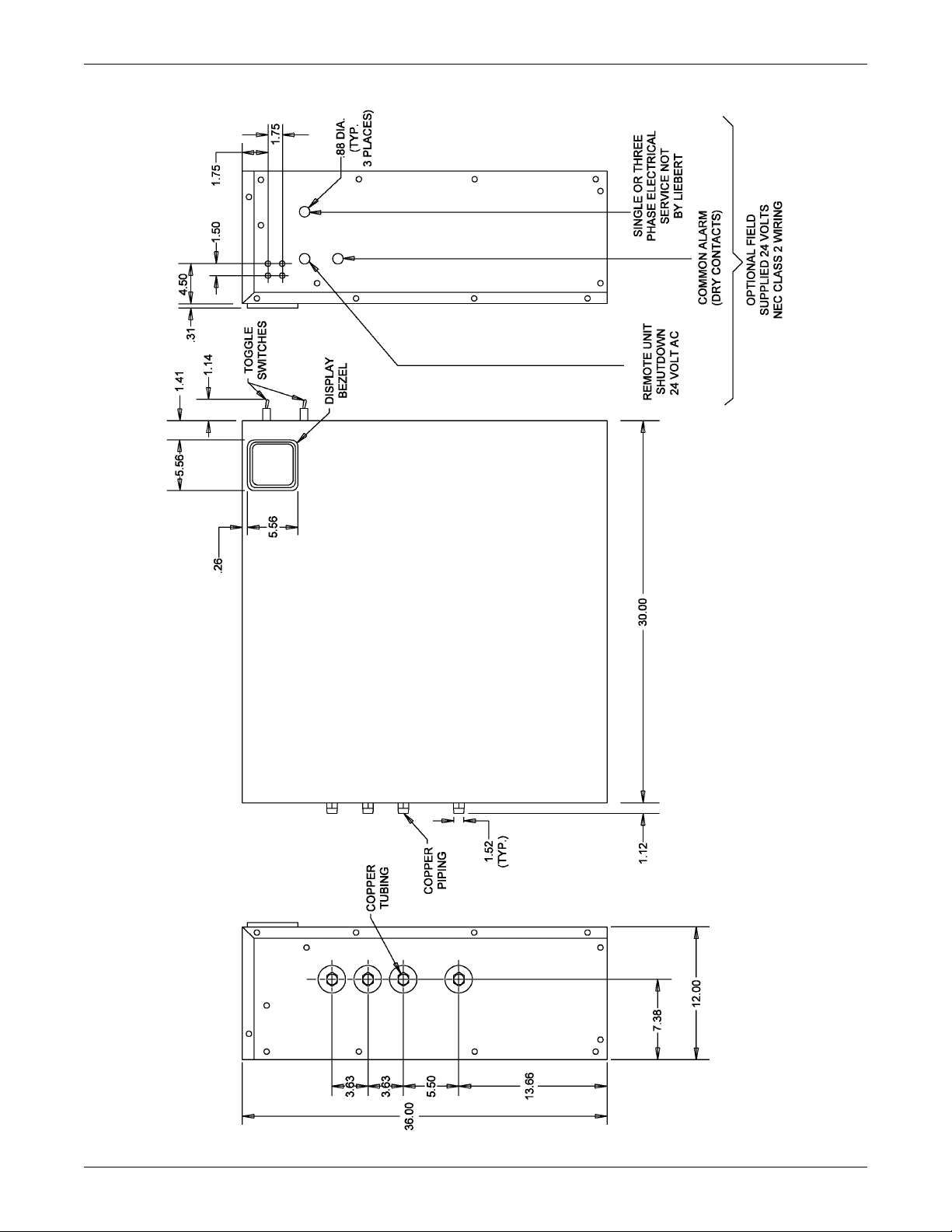
Figure 6 Cabinet dimensions for Envirosource ENV05G and ENV10G
Maintenance
11
Page 16

Figure 7 Cabinet dimensions for Envirosource ENV20G
Maintenance
12
Page 17

Figure 8 Electrical schematic
Maintenance
13
Page 18

Maintenance
14
Page 19

Page 20

Ensuring The High Availability
0f Mission-Critical Data And Applications.
Emerson Network Power, the global leader in enabling business-critical
continuity, ensures network resiliency and adaptability through
a family of technologies—including Liebert power and cooling
technologies—that protect and support business-critical systems.
Liebert solutions employ an adaptive architecture that responds
to changes in criticality, density and capacity. Enterprises benefit
from greater IT system availability, operational flexibility and
reduced capital equipment and operating costs.
While every precaution has been taken to ensure the accuracy
and completeness of this literature, Liebert Corporation assumes no
responsibility and disclaims all liability for damages resulting from use of
this information or for any errors or omissions.
© 2006 Liebert Corporation
All rights reserved throughout the world. Specifications subject to change
without notice.
® Liebert and the Liebert logo are registered trademarks of Liebert
Corporation. All names referred to are trademarks
or registered trademarks of their respective owners.
Technical Support / Service
Web Site
www.liebert.com
Monitoring
800-222-5877
monitoring@emersonnetworkpower.com
Outside the US: 614-841-6755
Single-Phase UPS
800-222-5877
upstech@emersonnetworkpower.com
Outside the US: 614-841-6755
Three-Phase UPS
800-543-2378
powertech@emersonnetworkpower.com
Environmental Systems
800-543-2778
Outside the United States
614-888-0246
Locations
United States
1050 Dearborn Drive
P.O. Box 29186
Columbus, OH 43229
Europe
Via Leonardo Da Vinci 8
Zona Industriale Tognana
35028 Piove Di Sacco (PD) Italy
+39 049 9719 111
Fax: +39 049 5841 257
Asia
7/F, Dah Sing Financial Centre
108 Gloucester Road, Wanchai
Hong Kong
852 2572220
Fax: 852 28029250
SL-15700_REV1_08-06
Emerson Network Power.
™
The global leader in enabling Business-Critical Continuity
AC Power Systems
Connectivity
DC Power Systems
Business-Critical Continuity, Emerson Network Power and the Emerson Network Power logo are trademarks and service marks of Emerson Electric Co.
©2006 Emerson Electric Co.
Embedded Computing
Embedded Power Power Switching & Control
Integrated Cabinet Solutions
.
Precision Cooling
EmersonNetworkPower.com
ServicesOutside Plant
Site Monitoring
Surge Protection
 Loading...