

Page 1
Instruction Manual
D103585X012
February 2021
EN-DFA Series
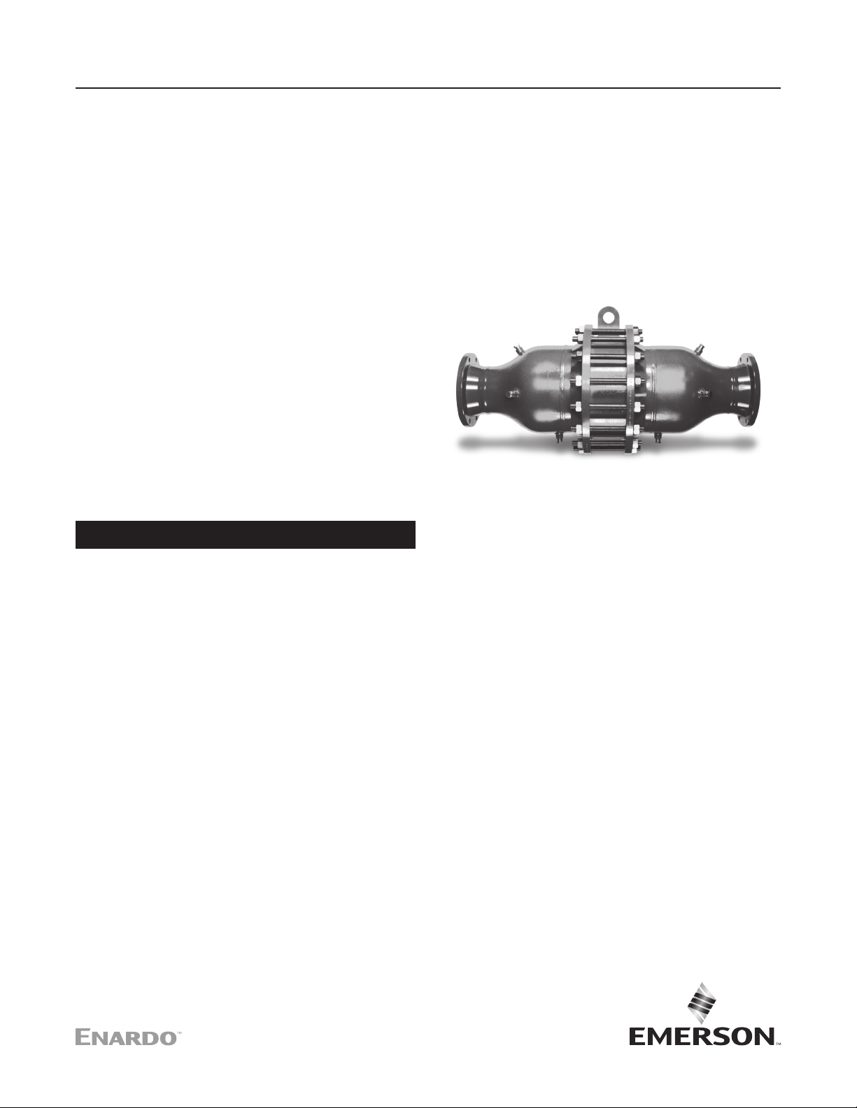
EN-DFA Series Detonation Flame Arrestor
(EN ISO 16852 Certied)
Table of Contents
Introduction .................................................................. 1
Product Description .................................................... 2
Specifications .............................................................. 2
Principle of Operation .................................................. 3
Factors Affecting Flame Arrestor Performance ............ 5
Installation ................................................................... 8
Maintenance .............................................................. 10
Recommended Spare Parts ...................................... 12
Parts Ordering ........................................................... 12
Figure 1. Typical EN-DFA Series Detonation Flame Arrestor
WARNING
▲
Failure to follow these instructions or
to properly install and maintain this
equipment could result in an explosion,
re and/or chemical contamination
causing property damage and personal
injury or death.
Enardo™ detonation ame arrestor must
be installed, operated and maintained
in accordance with federal, state and
local codes, rules and regulations
and Emerson Process Management
Regulator Technologies Tulsa,
(Emerson) LLC instructions.
Failure to correct trouble could result in
a hazardous condition. Call a qualied
service person to service the unit.
Installation, operation and maintenance
procedures performed by unqualied
person may result in improper adjustment
and unsafe operation. Either condition may
result in equipment damage or personal
injury. Only a qualied person must install
or service the detonation ame arrestor.
Introduction
Scope of the Manual
This Instruction Manual provides instructions for
installation, startup, maintenance and parts ordering
information for the EN-DFA Series detonation
ame arrestor.
Flame Arrestor Classication
The ame arrestors within the scope of this
document have been tested and certied as unstable
detonation ame arrestors and are therefore suitable
for deagrations, stable detonations and unstable
detonations, as dened by EN ISO 16852:2016,
propagating along pipe into connecting pipework.
This is the highest performance rating available for a
detonation arrestor and it exceeds the performance
rating of an arrestor certied for stable detonations and
deagrations only.
Detonation ame arrestors may be used for open and
closed pipe work on the unprotected (“hot”) side.
North America Only
Page 2
EN-DFA Series
Specications
The Specications table lists the specications for the detonation ame arrestors. The following information
is stamped on the nameplate attached to the arrestor: model number, ange size and rating, maximum initial
operating pressure, ISO reference number (International Standard), ISO type examination certicate, notied
body number, gas group, date of manufacture and serial number; other identication and customer tag number
are optional.
Available Constructions
See Table 1 and Figure 3
Operational Temperature (To)
-4 to 140°F / -20 to 60°C
(1)
Gas Group
IIA and IIB3
Flange Sizes and Rating
2 to 12 in. / 50 to 300 mm
Temperature Rating of Metal Reinforced Graphite
850°F / 450°C
Burning Time Rating
Less than 1 minute
CL150 RF and CL150 FF (standard)
Other connection ange sizes and ratings available
upon request
Housing Size
4 to 26 in. / 100 to 660 mm
Maximum Experimental Safe Gap (MESG)
Housing Material
Carbon steel, 304 Stainless steel,
316 Stainless steel and Hastelloy
Element Material
304 Stainless steel, 316 Stainless steel
and Hastelloy
®
See Table 4
EN Number (European Standard)
Maximum Initial Operating Pressure
EN ISO 16852:2016
See Table 5
1. The pressure/temperature limits in this Instruction Manual and any applicable standard or code limitation should not be exceeded.
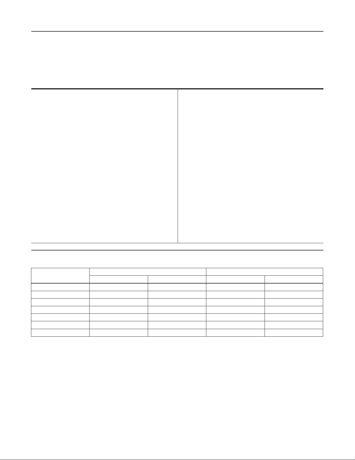
Table 1. EN-DFA Series Detonation Flame Arrestor Available Construction (ATEX Approved)
MODEL
EN-DFA-0402 2 50 4 101
EN-DFA-0603 3 75 6.6 168
EN-DFA-0804 4 100 10 254
EN-DFA-1206 6 150 14 356
EN-DFA-1608 8 200 18 457
EN-DFA-2010 10 250 22 559
EN-DFA-2412 12 300 26 660
In. mm In. mm
FLANGE SIZE HOUSING SIZE
(1)
®
North America Only
Product Description
The EN-DFA Series detonation ame arrestor represents
the best value in ame arrestor protection. The
detonation ame arrestor provides protection against
ame propagation in piping systems that are manifolded
or have long run-up distances. These are typically
used for extended pipe length or multiple pipe bend
congurations to stop high pressures and ame velocities
with detonations and overdriven detonations. It also
stops conned and unconned, low and high pressure
Hastelloy® is a mark owned by Haynes International, Inc.
2
deagrations. The design is unique in the ability to
provide large ame channels which requires less frequent
maintenance and greater ease in cleaning when service
is required, translating to less down time. EN-DFA Series
detonation ame arrestors are bi-directional and proven
to stop an ignited ammable vapor mixture approaching
from either direction that can be travelling at subsonic
or supersonic velocities. The patented element oers
maximum ow to pressure drop characteristics enhancing
the value of the ame arrestor in any system.
Page 3
EN-DFA Series
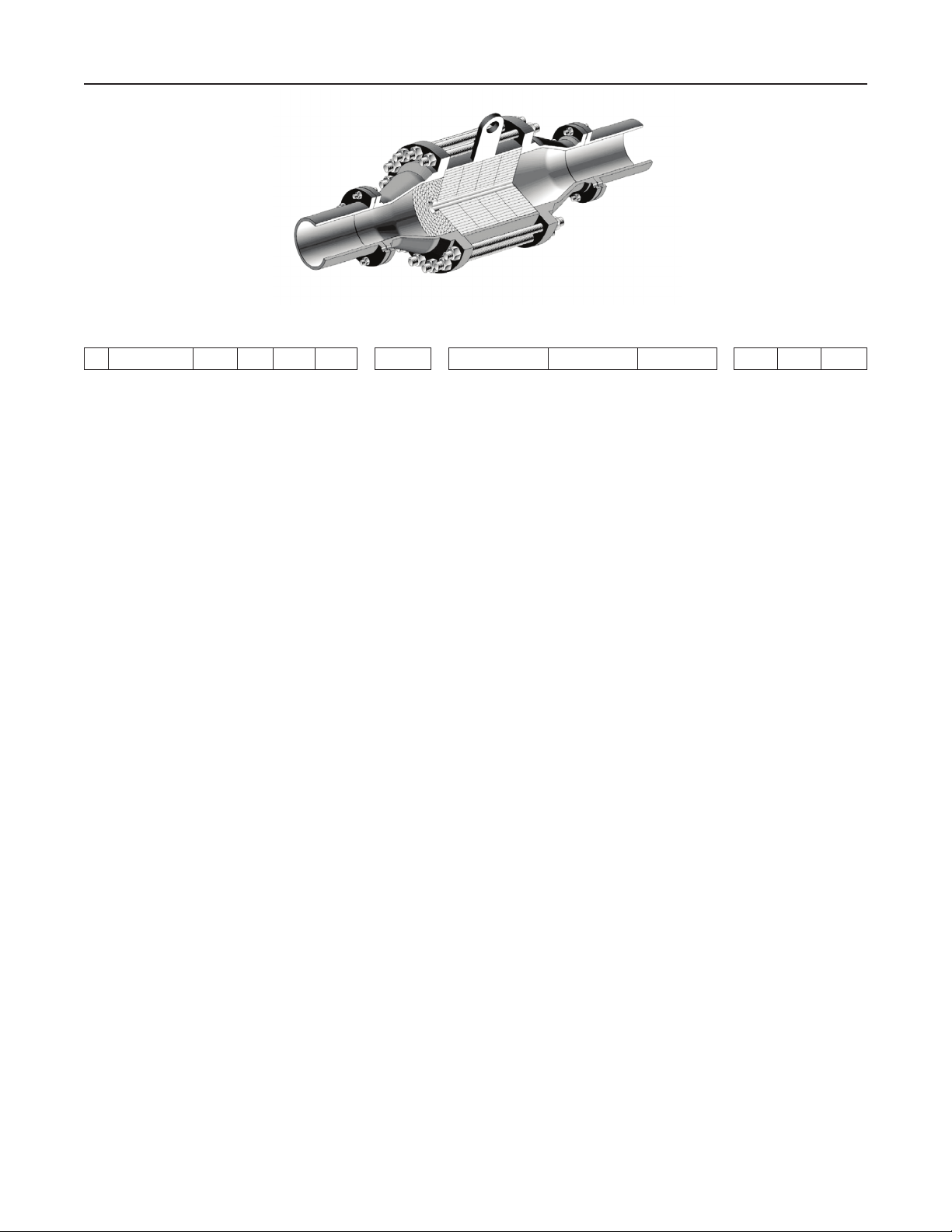
Figure 2. Cut-away view of EN-DFA Series Detonation Flame Arrestor
EN DFA / - -
Detonation
Flame
Arrestor
(Concentric)
Housing
Size
04 = 4 in.
through
26 = 26 in.
Connection
Size
02 = 2 in.
through
12 = 12 in.
IEC
Gas
Group
IIA (D)
IIB3 (C)
Housing
Material
C = Carbon Steel
4 = 304 SST
6 = 316 SST
H = Hastelloy
®
Element
Material
4 = 304 SST
6 = 316 SST
H = Hastelloy
Connection
F = Flat face
®
R = Raised
Type
ange
face
ange
Options
1 = Drain Plug
2 = Pressure Tap
3 = Temperature Probe
Tap (standard)
4 = Miscellaneous
5 = Protective coating
6 = Special feature
Figure 3. EN-DFA Series Detonation Flame Arrestor Available Constructions and Model Numbering System
The EN-DFA Series is designed with anged connections,
and the arrestor provides the option of the removal of the
ame cell element for easy cleaning and replacement
without disconnecting of the pipe connection.
Principle of Operation
Detonation ame arrestor prevents ame propagation
as it enters the exposed side of the unit to the
protected side by absorbing and dissipating heat
using spiral wound crimped ribbon ame cells.
This detonation ame arrestor utilizes a patented
element assembly that dampens the high velocities
and pressures associated with deagrations and
detonations while quenching the ame front. These
cells allow maximum ow with maximum protection.
Detonation ame arrestor has the heat capacity
and structural design to withstand all the dynamic
conditions of ame propagation and still stop the
ame. Detonation ame arrestor is used when the
ame can be in any of the detonation states.
Limits for Use
The operational temperature, T0, shall be limited
as follows:
-4°F ≤ T0 ≤ 140°F / -20°C ≤ T0 ≤ 60°C
The operation pressure, p0, shall be limited as follows:
See Table 5
Hastelloy® C is a mark owned by Haynes International, Inc.
Flame arrestor use shall be limited to gas-air mixtures
with an Maximum Experimental Safe Gap (MESG)
equal to or greater than that tested.
Additional Protection Measures: Flame arrestors
may be used with additional protection measures.
The overall safety of the combined installation shall
be accessed, taking account of any hazardous area
classication (zones) and the likelihood of additional
ignition sources.
Factors Aecting Flame
Arrestor Performance
Gas Group
The type of gas in the system determines its gas
grouping and therefore predetermines the type of
arrestor element required. The element must be
designed to accommodate the specic gas group that
could possibly ignite and propagate in the system.
The more explosive gases require the ame cell to
absorb the heat more quickly and eciently. The
International Electrotechnical Commission (IEC)
groups gases and vapors into Groups IIA through IIC
categories depending on a number of factors including
the MESG of the gas.
North America Only
3
Page 4
EN-DFA Series
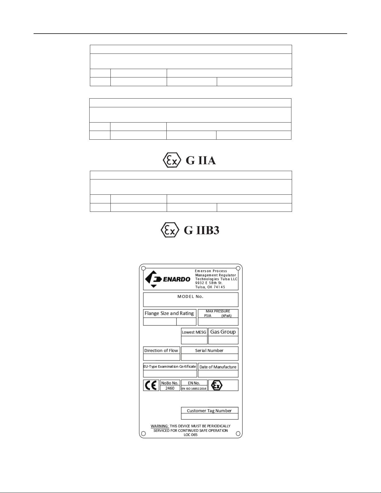
Flame Arrestors have installation and application limits
Type designation in accordance with EN ISO 16852:2016
DET 2 L
WARNING LABEL OF EN-DFA-0402/IIA THROUGH EN-DFA-1206/IIA (SEE TABLE 2)
Flame Arrestors have installation and application limits
Type designation in accordance with EN ISO 16852:2016
DET 2 L
WARNING LABEL OF EN-DFA-1608/IIA THROUGH EN-DFA-2412/IIA (SEE TABLE 2)
Flame Arrestors have installation and application limits
Type designation in accordance with EN ISO 16852:2016
DET 2 L
WARNING LABEL OF EN-DFA-0402/IIB3 THROUGH EN-DFA-2412/IIB3 (SEE TABLE 2)
/D = n/a
u
Ex. G IIA T
/D = n/a
u
Ex. G IIA T
/D = n/a
u
Ex. G IIB3 T
WARNING
BC: b; t
o
= 1 min
BT
= 60°C Po = 122.3 kPa (absolute)
WARNING
BC: b; t
o
= 1 min
BT
= 60°C Po = 116.3 kPa (absolute)
WARNING
BC: b; t
o
= 1 min
BT
= 60°C Po = 118.3 kPa (absolute)
HAZARDOUS LOCATIONS
Figure 4. Product Identification and Marking
North America Only
Figure 5. Marking Plate
4
Page 5

EN-DFA Series
Table 2. Warning Label Information
INFORMATION DESCRIPTION
DET Indicates product is a Detonation Flame Arrestor
2 Tested for unstable detonation without restriction
/D = n/a The ratio of pipe length (between the potential ignition source and the ame arrestor) and pipe diameter. It indicates unlimited
L
u
BC: b Indicates the ame arrestor is for short-time burning not to exceed 1 minute
Ex. G IIA Indicates the arrestor is rated for use in Explosion Group IIA vapors
Ex. G IIB3 Indicates the arrestor is rated for use in Explosion Group IIB3 vapors
T
o
P
o
MARKING PLATE FIELD MARKING
MODEL No. Per order, ex. EN-DFA-1206/IIA-C4R-2
Flange Size and Rating Per order, ex. 3 in CL150
Max Pressure (P
Lowest MESG Appropriate value from Table 4
Gas Group IIA or IIB3, per order
Direction of Flow Bi-directional. If product ordered with (1) temperature sensor, ow arrow will be added to unit
Serial Number
EU-Type Examination Certicate
Date of Manufacture
Customer Tag Number
) Appropriate value from Table 5
o
Indicates maximum operational temperature of ame arrestor
Indicates maximum operational pressure of ame arrestor
Table 3. Marking Plate Information
Per order
Based on unit ordered
Date of manufacture
Based on customer request
Table 4. Maximum Experimental Safe Gap (MESG)
NATIONAL ELECTRIC CODE
(NEC)
Group D Group IIA > 0.035 > 0.90 Propane
Group C Group IIB3 ≥ 0.026 ≥ 0.65 Ethylene
Group B Group IIC < 0.020 < 0.50 Hydrogen
INTERNATIONAL
ELECTROTECHNICAL
COMMISSION (IEC)
Table 5. Maximum Initial Operating Pressure P
EXPLOSION GROUP
IIA 2 to 6 50 to 150 17.7 122.3
IIA 8 to 12 200 to 300 16.9 116.3
IIB3 2 to 12 50 to 300 17.2 118.3
CONNECTION SIZE P
In. mm psia kPa a
Maximum Experimental Safe Gap (MESG)
The MESG is the measurement of the maximum gap
between two equatorial anges on a metal sphere that
will prevent a ame from being transmitted from the
sphere to the surrounding ammable mixture. MESG
is dependent on gas composition. The stoichiometric
mixture (the ideal air/fuel ratio for the most ecient
combustion) is used to determine the minimum MESG
for a given gas.
MESG
In. mm
o
Maximum Initial Operating Pressure, p
TEST GAS LIST
O
0
Detonation ame arrestors tested at pTB (pressure
before ignition) are suitable for operational pressures
p0 ≤ pTB in the same or smaller pipe size when the
application is limited to mixtures with an MESG equal
to or greater than that tested. See Table 5 for maximum
initial operating pressure limits, p0. If p0 is exceeded
at the time of ignition, there is a risk of the ame
arrestor being unable to stop the ame front and ame
transmission through the ame arrestor is possible.
North America Only
5
Page 6

EN-DFA Series
Table 6. Temperature Sensor Safety Specifications
TECHNICAL DATA THERMOCOUPLE
Design Type Standard with thermowell Standard without thermowell
Model 185 03J1 Code 0185 thermocouple (IEC 584 Class 1) without thermowell
Manufacturer Emerson Rosemount Emerson Rosemount
EC-Type Approval Certificate
Temperature Sensor Design Type-K thermocouple Type-K thermocouple
Type of Ignition Protection
Protection Type (Connection Head)
Measuring Probe (Measuring Insert) 1/2 MPT or optional M24 x1.5. Intended for installation into thermowell. 1/2 MPT. Intended for installation without thermowell.
Connection Thread 1/2 MPT. Intended for installation into thermowell 1/2 MPT. Intended for installation without thermowell.
Transmitter Optional by customer request Optional by customer request
Intended Application In-line flame arrestors and detonation arrestors End-of-line flame arrestors. Free-vent style.
TECHNICAL DATA THERMOCOUPLE
Design Type Standard with thermowell Standard without thermowell
Model TC 10-2 (for additional Thermowell) TC10-H (threaded for direct insertion without thermowell)
Manufacturer WIKA WIKA
EC-Type Approval Certificate ATEX and IECEx certifications ATEX and IECEx certifications
Temperature Sensor Design Type-K thermocouple Type-K thermocouple
Type of Ignition Protection
Protection Type (Connection Head)
Measuring Probe (Measuring Insert)
Connection Thread 1/2 MPT or optional M24 x1.5. Intended for installation into thermowell. 1/2 MPT. Intended for installation without thermowell.
Transmitter Optional by customer request Optional by customer request
Intended Application In-line flame arrestors and detonation arrestors End-of-line flame arrestors. Free-vent style.
FM12ATEX0065X
ATEX: EN 60079-0:2012+A11:2013; EN 60079-1: 2014
II 2 G Ex d IIC T6...T1 Gb, T6(–50°C ≤ Ta ≤ + 40°C), T5...
T1 (–50°C ≤ Ta ≤ + 60°C)
Rosemount Aluminum
Explosion proof, 2-wire, 3-wire, 4-wire type A, 4-Wire type as specified
by customer
Intrinsically safe option is available
II 2 G Ex d IIC T6...T1 Gb, T6(–50°C ≤ Ta ≤ + 40°C), T5...
T1 (–50°C ≤ Ta ≤ + 60°C)
Explosion proof, 2-wire, 3-wire, 4-wire type A, 4-Wire type as specified
by customer.
Intrinsically safe option is available .
Spring loaded plate
Probe allows use of transmitter.
Length varies by flame arrestor size.
FM12ATEX0065X
ATEX: EN 60079-0:2012+A11:2013; EN 60079-1: 2014
II 2 G Ex d IIC T6...T1 Gb, T6(–50°C ≤ Ta ≤ + 40°C), T5...
T1 (–50°C ≤ Ta ≤ + 60°C)
Rosemount Aluminum
Explosion proof, 2-wire, 3-wire, 4-wire type A, 4-Wire type as specified
by customer
Intrinsically safe option is available
II 2 G Ex d IIC T6...T1 Gb, T6(–50°C ≤ Ta ≤ + 40°C), T5...
T1 (–50°C ≤ Ta ≤ + 60 °C)
Explosion proof, 2-wire, 3-wire, 4-wire type A, 4-Wire type as specified
by customer.
Intrinsically safe option is available.
Probe length varies by flame arrestor size.
Adjustable insertion length.
North America Only
Table 7. Torque Values for Raised Face Connection Flange (Steel Only)
NOMINAL PIPE DIAMETER NUMBER OF BOLTS
1 4 0.50 12.70 9 12.20
1-1/4 4 0.50 12.70 13 17.63
1-1/2 4 0.50 12.70 18 24.40
2 4 0.63 16.00 35 47.45
2-1/2 4 0.63 16.00 41 55.59
3 4 0.63 16.00 60 81.35
3-1/2 8 0.63 16.00 34 46.10
4 8 0.63 16.00 43 58.30
6 8 0.75 19.05 80 108.5
8 8 0.75 19.05 109 147.8
10 12 0.88 22.4 101 136.9
12 12 0.88 22.4 135 183.0
Assumptions: Use of SAE grade 5 bolts or studs or stronger
Notes: If lubricant is used on bolts, apply torque reduction factor listed in Lubricant Table. For best results hardened steel washers should be used on all cast flange bolted connections.
No lubricant
Compressed mineral fiber material or similar
6
BOLT DIAMETER TORQUE
In. mm Ft-lb N•m
Page 7

EN-DFA Series
Table 8. Torque Values for Flat Face Connection Flange (Steel Only)
NOMINAL PIPE DIAMETER NUMBER OF BOLTS
1 4 0.50 12.70 14 18.98
1-1/4 4 0.50 12.70 16 21.69
1-1/2 4 0.50 12.70 18 24.41
2 4 0.63 16.00 32 43.39
2-1/2 4 0.63 16.00 43 58.30
3 4 0.63 16.00 47 63.72
3-1/2 8 0.63 16.00 26 35.25
4 8 0.63 16.00 32 43.39
6 8 0.75 19.05 49 66.44
8 8 0.75 19.05 68 92.20
10 12 0.88 22.4 69 93.55
12 12 0.88 22.4 98 132.9
Assumptions: Use of SAE grade 5 bolts or studs or stronger
Notes: If lubricant is used on bolts, apply torque reduction factor listed in Lubricant Table. For best results hardened steel washers should be used on all cast flange bolted connections.
No lubricant
Elastomer < 70 Durometer Shore A
Table 9. Torque Correction Factors for Common Lubricants Applied on Connection Fasteners
DESCRIPTION COEFFICIENT OF FRICTION MULTIPLY TORQUE VALUE IN TABLE 8 BY
Machine Oil f = 0.15 0.75
API SA2 Grease f = 0.12 0.60
Nickel-based Lubricant f = 0.11 0.55
Copper-based Lubricant f = 0.10 0.50
Molydisulfide Based Lubricating Paste f = 0.06 0.30
BOLT DIAMETER TORQUE
In. mm Ft-lb N•m
Burn Time Rating
WARNING
▲
Temperature sensors must be used with
this product if there is a potential for
stabilized burning inside the arrestor.
Additional external safety equipment
is required to ensure appropriate
corrective measures are taken within
30 seconds to protect the system if an
abnormal temperature is detected. Never
disconnect or remove these devices in
active process systems.
All Model EN-DFA detonation ame arrestors are rated
for short time burning, tBT not to exceed one minute in
accordance with EN ISO 16852:2016. This burn time
was determined at atmospheric pressure. If there are
operating conditions which can lead to a stabilized
burning event, additional safety measures are
required. Depending on the operating conditions, the
devices shall be equipped with temperature sensors
on one or both sides of the ame arrestor element.
These temperature sensors are installed into the
system in such a way that they trigger the initiation of
measures for the elimination of the stabilized burning
(for example, emergency functions like switchingo the system, inerting or similar). These measures
must occur within half of the time for which the ame
arrestor is short-time burn proof (0.5 x t
). See Figure
BT
4 for warning labels showing burn rating, tBT. This
requires that measures must be able to be taken within
30 seconds.
Threaded instrumentation ports, with standard 3/4 NPT
threads, are integrated into each end section. Other
instrumentation port thread sizes can be requested.
If the user requests the addition of temperature
sensors by Emerson, they will either be installed and
shipped threaded into the appropriate instrumentation
ports in the ame arrestor end sections or shipped
separately with the ame arrestor. To install the
temperature sensors that have been shipped
separately, simply remove any protective packaging
from the temperature sensors and thread the
temperature sensors into the appropriate threaded
instrumentation ports on the ame arrestor end
sections making sure to follow temperature sensor
manufacturer’s instructions, particularly for wiring.
In the case where only one temperature sensor was
requested from Emerson, the ame arrestor will be
marked with a ow arrow to indicate ow direction
and the temperature sensor will be installed on the
downstream or unprotected (“hot”) side of the ame
arrestor. This is the side of the ame arrestor closest
to the source of ignition. If the temperature sensor is
shipped separately, the user shall be responsible for
North America Only
7
Page 8

EN-DFA Series
4
8
1
1
4
5
8
4
1
12
5
9
2
3
1 2
16
12
8
4
14
10
6
2
Figure 6. Flange Pattern Tightening Sequence
6
2
1
5
9
13
3
7
11
15
installing the temperature sensor in the appropriate
instrumentation port on the downstream or unprotected
(“hot”) side of the ame arrestor. Model EN-DFA
detonation ame arrestors are bi-directional, so if a
temperature sensor is not requested with the ame
arrestor, then no ow arrow will be installed on the unit,
and the end user shall be responsible for installation of
the temperature sensor on the unprotected (“hot”) side
of ame arrestor. This is the side of the ame arrestor
closest to the source of ignition.
A temperature rise of 20 K (36°F / 20°C) above the
ame arrestor maximum operating temperature or 20 K
(36°F / 20°C) above the process operating temperature,
whichever is lower but not to exceed 20 K (36°F / 20°C)
above the ame arrestor operating temperature, is the
recommended activation temperature for initiation of
measures against stabilized burning.
Note that a rise in temperature measured by
the temperature sensor can indicate to the user
deagration and/or detonation events have occurred
as well. This should be used as a trigger to investigate
what conditions have lead to ignition of ammable
vapors, to inspect the ame arrestor for damage, and
to initiate appropriate corrective actions relative to
process system and safety.
Temperature sensors installed by Emerson or installed
by the user shall follow the specications or Table 6.
Dierent temperature sensors may be installed by
the end user, however these must comply with the
safety specications in Table 6. The use of alternate
8
3
7
16
12
8
4
18
14
10
6
10
6
2
3
1
20
5
9
13
17
3
7
11
15
19
2
54
3
7
11
temperature sensors must include evidence of
equivalent response rates to the specied sensors in
Table 6, particularly as the EN-DFA Series is rated for
short time burning.
If tBT is exceeded during a short-time burning situation,
the ame arrestor safety cannot be assured.
If an elevated temperature has been detected by
the temperature sensor, whether due to ash back
or stabilized burn, the temperature sensor shall be
inspected for damage and replaced as necessary.
If the recorded temperature exceeds the design
temperature of the temperature sensor then the
measuring probe shall be replaced.
Pipe Length
Extended lengths of pipe allow the ame to advance
into more severe states of ame propagation such as
high pressure deagrations and detonations. Although
the detonation ame arrestor is not limited by pipe
length, using a minimum length is a preferred design
and installation practice.
Bends and/or Flow Obstructions
CAUTION
△
For maximum safety, avoid bends
and ow obstructions within 10 pipe
diameters but not less than 10 ft / 3 m
on the protected side of the detonation
ame arrestor.
North America Only
Page 9

EN-DFA Series
-LB / N•m)
(1)(2)
Table 10. Tightening Steps and Torque Values for Body Fasteners for Element Assembly
MODEL PATTERN
EN-DFA-402 1 5/8-11 Snug 10 / 14 35 / 47
EN-DFA-603 2 3/4-10 Snug 30 / 41 80 / 108
EN-DFA-804 2 3/4-10 Snug 50 / 68 100 / 135 160 / 217
EN-DFA-1206 3 7/8-9 Snug 50 / 68 100 / 135 175 / 237
EN-DFA-1608 4 1-8 Snug 50 / 68 120 / 163 200 / 271 285 / 386
EN-DFA-2010 5 1-1/8-8 Snug 50 / 68 120 / 163 200 / 271 310 / 420
EN-DFA-2412 5 1-1/4-8 Snug 75 / 102 150 / 203 280 / 380 400 / 542 535 / 725
1. Using machine oil as lubricant. See Bolt Lubrication section on page 12 and torque correction factors for other lubricants in Table 11.
2. Alloy steel element assembly fasteners are provided with a low friction polymer coating. No additional lubrication should be required. When stainless steel fasteners are provided,
lubrication is recommended to reduce tightening torque and to prevent potential galling.
3. See Figure 6.
DESCRIPTION COEFFICIENT OF FRICTION MULTIPLY TORQUE VALUE IN TABLE 7 BY
API SA2 Grease f = 0.12 0.80
Nickel-based Lubricant f = 0.11 0.73
Copper-based Lubricant f = 0.10 0.67
Molydisulde Based Lubricating Paste f = 0.06 0.40
(3)
BOLT SIZE
Table 11. Torque Correction Factors for Common Lubricant
Machine Oil f = 0.15 1.00
1 2 3 4 5 6
Bends in piping, pipe expansions and/or contractions,
valves, orice plates or ow obstructing devices of any
kind cause turbulent ow. Turbulent ow enhances
mixing of the combustible gases, greatly increasing
the combustion intensity. This can result in increased
ame speeds, higher ame temperatures and higher
ame front pressures than would occur in normal
ow conditions. Obstructions in protected side piping
can cause reective pressures that might inhibit the
eective performance of the EN-DFA Series under
certain conditions.
TIGHTENING STEPS AND TORQUE (FT
Standard compressed ber gaskets that will withstand
temperatures of 450°F / 232°C or higher are normally
used, but other materials of equal or higher temperature
capability may be used at the customer’s discretion.
Flow Direction
This EN-DFA Series is bi-directional and can be installed
either vertically or horizontally. Consideration should
be given to non-symmetrical assemblies that include
features such as clean-out ports, temperature sensors
or other devices that might have a preferred installation
direction to suit the needs of the customer. Compliance
Installation
with warning associated with temperature sensors is
essential. See Burning Time Rating section.
North America Only
WARNING
▲
Always make sure that the system is
at atmospheric pressure and there is
no ignitable gas that could ash when
either installing or maintaining the unit.
Connection
EN-DFA Series are normally provided with CL150 or
PN 16 raised or at faced anges. Other anges are
sometimes provided on special request. Make sure the
companion anges installed in adjacent piping match the
anges on the detonation ame arrestor.
For proper bolt torquing of the detonation arrestor to
the piping, please refer to Tables 7, 8 and 9.
Positioning
WARNING
▲
If the detonation ame arrestor is
equipped with a single factory installed
temperature sensor, the arrestor shall
be installed with the sensor on the
unprotected side of the arrestor, the side
nearest the potential source of ignition.
CAUTION
△
The detonation ame arrestor is
tted with lugs for lifting the element
assembly during servicing operations.
9
Page 10

EN-DFA Series
These lugs are not intended for lifting
the entire unit during installation.
Damage to the detonation ame arrestor
may result from improper lifting. The
unit should be lifted using appropriately
rated Nylon (PA) straps rigged on the
outside of the tension studs.
The arrestor should be positioned such that the entire
arrestor is accessible for removal. Models that have
drain plugs are designed for horizontal installation
and should be installed with the drain plugs aligned
at the bottom of the unit. Models that have pressure
taps are designed to allow pressure gauges to be
installed on both sides of the ame cell assembly
to determine blockage. The pressure taps should
be aligned at the top to allow easy viewing of the
gauges. Units that are equipped with optional internal
cleaning systems should be connected to a source of
cleaning media such as water, steam or other suitable
solvent. Observe recommended installation practice as
previously described.
Piping Expansions and Reductions
Adjacent to Detonation Flame Arrestor
WARNING
▲
a length of pipe at least 120 pipe diameters must be
installed between the detonation ame arrestor and
the expansion. A pipe diameter is considered as the
inside diameter of pipe having a nominal size equal to
the detonation ame arrestor’s connecting anges.
Maintenance
WARNING
▲
Isolate gas supply and bring system
to atmospheric pressure to prevent
ignitable gas from ashing while
performing maintenance.
CAUTION
△
The ame cells in the arrestor’s element
assembly are not retained once the
element assembly has been removed
from the arrestor. They can slide
out of the housing during handling.
It is recommended that the element
assembly only be removed after the
entire arrestor has been removed from
the piping system.
No instrument, tubing or other device
whatsoever shall circumvent the
detonation ame arrestor in such a
manner to allow a ame path to exist
around the ame element of the arrestor.
When instrumentation is installed in
such a manner that it creates a path
circumventing the ame element of an
arrestor, measures must be taken to
prevent passage of ame through the
instrumentation device and/or system.
Instrumentation must be capable of
withstanding the maximum and minimum
pressures and temperatures to which the
device may be exposed and at a minimum
be capable of withstanding a hydrostatic
pressure test of 350 psig / 24 bar.
For an in-line ame arrestor, the pipe diameter on
the protected (“cold”) side shall be no less than the
pipe diameter on the unprotected (“hot”) side. For
an in-line ame arrestor, the pipe diameter on the
unprotected (“hot) side shall be no greater than the
ame arrestor connection. When it is necessary to
increase the diameter of the piping on the downstream
side (unprotected) of the detonation ame arrestor,
Element Disassembly
1. Loosen all nuts on tension studs between conical
sections of the detonation ame arrestor.
CAUTION
△
Element assemblies are heavy and will
require the use of adequate equipment
and manpower to prevent injury.
2. Carefully force the two conical sections apart
while the nuts are still on the tension studs.
When the two ange faces have separated,
remove enough of the tension studs such that
the element assembly can be removed. Not all
studs are required to be removed to be able to
rotate the element assembly out of the housings.
It is possible for the elements to come out of the
housing once the end sections have been removed.
Inspecting and Cleaning the Flame Cells
1. Inspect ame cells for damage immediately
following a deagration, detonation and/or
stabilized burn.
North America Only
10
Page 11

EN-DFA Series
2. Carefully remove the element assembly from the
arrestor. Place the element assembly on a soft
surface such as plywood and push the ame cells
from the housing. It might be necessary to tilt the
housing to facilitate removal of the ame cells.
3. Note the order in which the ame cells were
removed. For Group IIA units, there are four 2 in. /
51 mm thick ame cells. For Group IIB3 units, the
outer two ame cells are 2 in. / 51 mm thick and
the two inner ame cells are 1 in. / 25 mm thick. A
screen of expanded metal is located between each
adjacent set of ame cells.
4. Inspect the ame cells and the screens visually
for any signs of corrosion or other damage and
inspect the ame cells with a calibrated pin gauge
to ensure maximum crimp size openings do not
exceed the following values for their respective
gas group:
• Explosion Group IIA – 0.051 in. / 1.295 mm
• Explosion Group IIB3 – 0.0216 in. / 0.549 mm
5. If any damage is noted or crimp openings exceed
maximum size allowable, the ame cells and/or
the screens must be replaced.
8. The cleaning interval should be governed by the
amount and type of particulate in the system to
which it is installed and must be determined by
the user. To determine the maintenance interval
the user should check the element in the rst few
months of operation to nd how quickly particulate
accumulates in the cells.
9. Thoroughly clean the gasket sealing faces being
careful not to damage the sealing surface. For
reassembly a new gasket must be used and
placed in the machined recess of each interior
ange on the two conical sections.
10. Replace the ame element assembly with a new
assembly or properly cleaned and inspected
existing unit.
11. Locate the ame cell assembly such that it seats
onto the gaskets.
12. Replace all tensioning studs and tighten the outer
nuts hand tight only.
13. Torque the bolts in sequence as shown in the
following instructions.
Torquing Instructions
Note
Under no circumstance shall any other
screens not provided by Emerson be used
in this assembly. Failure to use the correct
screens may lead to arrestor failure.
6. It is important to keep the element openings clean
to prevent loss of eciency in absorbing heat. The
element assembly should be removed and the
elements cleaned to prevent the openings from
becoming clogged with particulate matter or other
contaminants. Clean the element with a suitable
cleaning media (solvent, soap, water or steam)
then blow dry using compressed air. Special care
should be taken not to damage or dent the cell
openings as this would hamper the eectiveness
of the unit. Arrestor elements shall not be cleaned
by rodding with wire or other hard objects to
remove blockages, as this practice could damage
the elements and seriously impair the arrestor’s
performance. If the arrestor element cannot be
cleaned satisfactorily, it must be replaced.
7. For best cleaning results, a high pressure sprayer
with spray wand should be used (1500 to 3000 psig /
103 to 207 bar) to clean the entire element surface.
The spray nozzle should be held perpendicular to
the surface being cleaned to maximize spray media
penetration into the element. Alternately spray each
side of the element surface until clean.
CAUTION
△
Excessive or uneven torque can cause
permanent damage to gaskets
and housing.
Tools/Supplies Required
• Hand operated conventional torque wrench or
power assisted torque wrench appropriate for the
specied torque.
• Socket wrenches of the proper size to t the hex
nuts being tightened.
• Lubricant for fasteners, as appropriate.
• Brush suitable for applying lubricant to the studs.
• Wiping rags necessary for the clean up of
excessive lubricant.
Procedure
1. Use studs and nuts that are free of visible
contamination and corrosion.
2. Apply lubricant to the threads of the stud protruding
outboard of the interior anges and to the face of the
hex nuts which will contact the ange for stainless
steel fasteners. Alloy steel fasteners have a polymer
coating and do not require additional lubrication.
North America Only
11
Page 12

EN-DFA Series
3. Assemble the nuts to the studs such that the
amount of thread extending outboard beyond the
nut is approximately equal on both ends.
4. Tighten the nuts to the torque values shown in
Table 10 following the designated sequence,
repeating he sequence as shown. Flange pattern
tightening sequences are shown in Figure 6.
Bolt Lubrication
Lubrication will aect required torque of clean
fasteners in good condition more than any other factor.
In fact, 90% of applied torque goes to overcome
friction while only 10% actually stretches the bolt.
Table 10 assumes that only factory polymer coating is
used for alloy steel fasteners and machine oil is used
for stainless steel fasteners as a lubricant. Table 9
shows a list of several common lubricants and their
eect on torque required to stretch bolts to 50% of
their yield strength. Most are available from local
bearing distributors.
Recommended Spare Parts
The crimp openings in Enardo™ detonation ame
arrestors are relatively large and are therefore quite
easy to clean. Plugging will normally be limited to the
ame cell and screen that are installed at the inlet side
of the arrestor’s element assembly. If plugging should
occur, the plugged ame cell(s) and screen(s) can be
cleaned as detailed above, reinstalled and used again,
provided there is no damage and not plugged to an
extent that cleaning is not eective. For installations
with dirty process conditions where frequent
maintenance is necessary, it is recommended that the
user purchase a spare element assembly and several
spare element gaskets. The spare element assembly
can be installed immediately and the dirty assembly
can then be cleaned and be stored as a spare for the
next maintenance interval.
Note
Element gaskets must be replaced each
time the cell assembly is loosened and
removed. Gasket must be made from
high temperature graphite material. It is
recommended that replacement gaskets
be ordered from Emerson.
Parts Ordering
When corresponding with your local Sales Oce
about this equipment, always reference the equipment
serial number and model number stamped on
the nameplate.
Webadmin.Regulators@emerson.com
Enardo.com
Emerson Automation Solutions
Americas
McKinney, Texas 75070 USA
T +1 800 558 5853
+1 972 548 3574
Tulsa, OK 74146 USA
T +1 918 662 6161
Europe
Bologna 40013, Italy
T +39 051 419 0611
Facebook.com/EmersonAutomationSolutions
LinkedIn.com/company/emerson-automation-solutions
Twitter.com/emr_automation
Asia Pacic
Singapore 128461, Singapore
T +65 6777 8211
Middle East and Africa
Dubai, United Arab Emirates
T +971 4 811 8100
D103585X012 © 2014, 2021 Emerson Process Management Regulator
Technologies, Inc. All rights reserved. 02/21.
The Emerson logo is a trademark and service mark of Emerson
Electric Co. All other marks are the property of their prospective owners.
Enardo™ is a mark owned by Regulator Technologies Tulsa, LLC, a
business of Emerson Automation Solutions.
The contents of this publication are presented for informational purposes
only, and while every eort has been made to ensure their accuracy,
they are not to be construed as warranties or guarantees, express or
implied, regarding the products or services described herein or their use
or applicability. We reserve the right to modify or improve the designs or
specications of such products at any time without notice.
Emerson Process Management Regulator Technologies
Tulsa, LLC does not assume responsibility for the selection, use or
maintenance of any product. Responsibility for proper selection, use
and maintenance of any Emerson Process Management Regulator
Technologies Tulsa, LLC product remains solely with the purchaser.
North America Only
 Loading...