

Page 1

Installation Manual
308014EN, Edition 4
May 2013
Tank Gauging System
www.rosemount-tg.com
Page 2

Page 3

Installation manual
Fourth edition
Copyright
© May 2013
Rosemount Tank Radar AB
www.rosemount-tg.com
Page 4

Copyright © May 2013
Rosemount Tank Radar AB
The contents, descriptions and specifications within this manual is
subject to change without notice. Rosemount Tank Radar AB accepts no
responsibility for any errors that may appear in this manual.
Trademarks
Rosemount, and the Rosemount logotype are trademarks of
Rosemount Inc.
TankRadar is a trademark of Rosemount Tank Radar AB.
HART is a trademark of HART Communication Foundation
Modbus is a trademark of Modicon.
Pentium is a trademark of Intel Corporation.
Windows NT is a trademark of Microsoft Corporation.
Viton is a trademark of Du Pont Performance Elastomers.
Spare Parts
Any substitution of non-recognized spare parts may jeopardize safety.
Repair, e.g. substitution of components etc, may also jeopardize safety
and is under no circumstances allowed.
Rosemount Tank Radar AB will not take any responsibility for faults,
accidents, etc caused by non-recognized spare parts or any repair which
is not made by Rosemount Tank Radar AB.
EU Conformity
The EC declaration of conformity for all applicable European directives
for this product can be found on the Rosemount Tank Gauging website
at www.rosemount-tg.com. A hard copy may be obtained by contacting
our local sales representative.
Specific FCC Requirements (USA only)
Rosemount TankRadar REX generates and uses radio frequency
energy. If it is not installed and used properly, that is, in strict accordance
with the manufacturer´s instructions, it may violate FCC regulations on
radio frequency emission.
Rosemount TankRadar REX has been FCC certified under test
conditions which assume a metallic tank. Installation on a non-metallic
tank is not certified, and is not allowed.
The FCC certificate for Rosemount TankRadar REX requires that the
tank is closed as far as emitted radio energy is concerned. Tanks with
open manholes, external-floating-roof tanks without still pipes etc. are
not covered by the certificate.
www.rosemount-tg.com
Page 5

Installation Manual
308014EN, Edition 4
May 2013
Rosemount TankRadar REX
Table of Contents
Contents
Recovery of Packing Material . . . . . . . . . . . . . . . . . . . . . . . . . . . . TOC-6
Recovery of Products . . . . . . . . . . . . . . . . . . . . . . . . . . . . . . . . . . . TOC-7
1. INTRODUCTION . . . . . . . . . . . . . . . . . . . . . . . . . . . . . . . . 1-1
1.1 MANUAL OVERVIEW . . . . . . . . . . . . . . . . . . . . . . . . . . . . . . . . . . . . . .1-4
2. SAFETY . . . . . . . . . . . . . . . . . . . . . . . . . . . . . . . . . . . . . 2-1
2.1 INTRINSIC SAFETY . . . . . . . . . . . . . . . . . . . . . . . . . . . . . . . . . . . . . . .2-1
2.2 EXPLOSION PROOF . . . . . . . . . . . . . . . . . . . . . . . . . . . . . . . . . . . . . .2-2
2.3 EUROPEAN ATEX DIRECTIVE INFORMATION . . . . . . . . . . . . . . . . .2-3
2.3.1 Radar Unit . . . . . . . . . . . . . . . . . . . . . . . . . . . . . . . . . . . .2-3
2.3.2 Radar Tank Gauge . . . . . . . . . . . . . . . . . . . . . . . . . . . . . .2-4
2.3.3 Transmitter Interface Card (TIC) . . . . . . . . . . . . . . . . . . . . 2-5
2.3.4 Temperature Multiplexer Card (TMC) . . . . . . . . . . . . . . . .2-6
2.3.5 Data Acquisition Unit . . . . . . . . . . . . . . . . . . . . . . . . . . . .2-7
2.3.6 Remote Display Unit 40 (RDU 40) . . . . . . . . . . . . . . . . . .2-8
3. DESCRIPTION OF 3900 REX . . . . . . . . . . . . . . . . . . . . . . 3-1
3.1 TRANSMITTER HEAD RTG 3900 REX . . . . . . . . . . . . . . . . . . . . . . . .3-1
3.1.1 Transmitter Head Electronics . . . . . . . . . . . . . . . . . . . . . .3-2
3.1.2 Analog Processing Card - APC . . . . . . . . . . . . . . . . . . . .3-3
3.1.3 Transmitter Interface Card - TIC . . . . . . . . . . . . . . . . . . . .3-3
3.1.4 Temperature Multiplexer Card - TMC . . . . . . . . . . . . . . . .3-3
3.1.5 Relay Output Card - ROC . . . . . . . . . . . . . . . . . . . . . . . . .3-3
3.1.6 Field Communication Card - FCC . . . . . . . . . . . . . . . . . .3-3
3.1.7 Metrological Seal . . . . . . . . . . . . . . . . . . . . . . . . . . . . . . .3-4
3.2 ANTENNA TYPES . . . . . . . . . . . . . . . . . . . . . . . . . . . . . . . . . . . . . . . .3-5
4. THE DATA ACQUISITION UNIT . . . . . . . . . . . . . . . . . . . . . 4-1
4.1 LOCAL READOUT DISPLAY . . . . . . . . . . . . . . . . . . . . . . . . . . . . . . . .4-1
4.2 WRITE ENABLE/INHIBIT SWITCH . . . . . . . . . . . . . . . . . . . . . . . . . . .4-2
4.3 CONNECTING THE DATA ACQUISITION UNIT, DAU 2100 . . . . . . . .4-3
4.3.1 Power Supply . . . . . . . . . . . . . . . . . . . . . . . . . . . . . . . . . .4-3
4.3.2 Temperature Sensors . . . . . . . . . . . . . . . . . . . . . . . . . . . .4-3
4.3.3 Selecting the temperature range . . . . . . . . . . . . . . . . . . .4-4
TOC-1
Page 6

Installation Manual
Rosemount TankRadar REX
Table of Contents
308014EN, Edition 4
May 2013
5. THE REMOTE DISPLAY UNIT RDU40. . . . . . . . . . . . . . . . 5-1
5.1 INSTALLATION . . . . . . . . . . . . . . . . . . . . . . . . . . . . . . . . . . . . . . . . . .5-2
5.2 TWO RDU 40 CONNECTED TO THE SAME REX . . . . . . . . . . . . . . .5-4
5.2.1 Data items . . . . . . . . . . . . . . . . . . . . . . . . . . . . . . . . . . . .5-4
6. THE FIELD COMMUNICATION UNIT . . . . . . . . . . . . . . . . . . 6-1
6.1 FCU ENCLOSURE . . . . . . . . . . . . . . . . . . . . . . . . . . . . . . . . . . . . . . . .6-1
6.2 COMMUNICATION PORTS . . . . . . . . . . . . . . . . . . . . . . . . . . . . . . . . .6-2
6.2.1 RS232 communication . . . . . . . . . . . . . . . . . . . . . . . . . . .6-2
6.2.2 RS 485 communication . . . . . . . . . . . . . . . . . . . . . . . . . .6-3
6.3 WRITE INHIBIT/ENABLE SWITCH . . . . . . . . . . . . . . . . . . . . . . . . . . .6-3
6.4 CONNECTING THE FIELD COMMUNICATION UNIT, FCU 2160 . . .6-4
6.4.1 Power Supply . . . . . . . . . . . . . . . . . . . . . . . . . . . . . . . . . .6-4
6.4.2 Connection to a PC . . . . . . . . . . . . . . . . . . . . . . . . . . . . .6-4
6.5 REDUNDANCY . . . . . . . . . . . . . . . . . . . . . . . . . . . . . . . . . . . . . . . . . . .6-5
7. BUS MODEMS. . . . . . . . . . . . . . . . . . . . . . . . . . . . . . . . . 7-1
7.1 FIELD BUS MODEM 2180 . . . . . . . . . . . . . . . . . . . . . . . . . . . . . . . . . .7-2
7.1.1 DIN Rail Mounting . . . . . . . . . . . . . . . . . . . . . . . . . . . . . .7-2
7.1.2 Power Supply . . . . . . . . . . . . . . . . . . . . . . . . . . . . . . . . . .7-3
7.1.3 TRL/2 Bus . . . . . . . . . . . . . . . . . . . . . . . . . . . . . . . . . . . . .7-3
7.1.4 RS 232 Communication . . . . . . . . . . . . . . . . . . . . . . . . . .7-4
7.1.5 USB Communication . . . . . . . . . . . . . . . . . . . . . . . . . . . .7-4
7.1.6 USB Driver Installation . . . . . . . . . . . . . . . . . . . . . . . . . . .7-5
7.1.7 Operation . . . . . . . . . . . . . . . . . . . . . . . . . . . . . . . . . . . . . 7-7
7.1.8 Communicating with TankMaster™ . . . . . . . . . . . . . . . . .7-7
7.1.9 USB Interface . . . . . . . . . . . . . . . . . . . . . . . . . . . . . . . . . .7-8
7.1.10 RS 232 Interface . . . . . . . . . . . . . . . . . . . . . . . . . . . . . . . .7-8
7.1.11 Specifications . . . . . . . . . . . . . . . . . . . . . . . . . . . . . . . . . .7-9
7.2 ENRAF BUS MODEM, EBM . . . . . . . . . . . . . . . . . . . . . . . . . . . . . . . .7-10
7.2.1 Connecting the Enraf Bus Modem . . . . . . . . . . . . . . . . . 7-11
7.2.2 Configuration . . . . . . . . . . . . . . . . . . . . . . . . . . . . . . . . . 7-11
8. JUNCTION BOXES . . . . . . . . . . . . . . . . . . . . . . . . . . . . . . 8-1
8.1 INTEGRATED JUNCTION BOX, JBI . . . . . . . . . . . . . . . . . . . . . . . . . .8-1
8.1.1 Explosion Approval . . . . . . . . . . . . . . . . . . . . . . . . . . . . . . 8-1
8.1.2 Design . . . . . . . . . . . . . . . . . . . . . . . . . . . . . . . . . . . . . . .8-2
8.1.3 Cable Inlets - RTG 3900 . . . . . . . . . . . . . . . . . . . . . . . . . . 8-2
TOC-2
Page 7

Installation Manual
308014EN, Edition 4
May 2013
8.2 JUNCTION BOXES FOR INTRINSICALLY SAFE AND
EEX E ENVIRONMENTS . . . . . . . . . . . . . . . . . . . . . . . . . . . . . . . . . . .8-3
8.2.1 JB 140-11 for EEx i environments . . . . . . . . . . . . . . . . . .8-3
8.2.2 JB 140-15 for EEx e environments . . . . . . . . . . . . . . . . . . 8-3
8.2.3 Junction Boxes with Conduit Outlets . . . . . . . . . . . . . . . .8-4
8.3 CONNECTION OF TEMPERATURE SENSORS . . . . . . . . . . . . . . . . .8-5
8.3.1 Junction Box JBT . . . . . . . . . . . . . . . . . . . . . . . . . . . . . . .8-5
8.3.2 Junction Box JB 36/42 . . . . . . . . . . . . . . . . . . . . . . . . . . . 8-6
Rosemount TankRadar REX
Table of Contents
9. CONNECTION TO COMPUTER NETWORKS. . . . . . . . . . . . . 9-1
9.1 CONNECT TO THE FCU FOR QUICK UPDATES . . . . . . . . . . . . . . . .9-1
9.2 CONNECT TO TANKMASTER FOR INVENTORY DATA . . . . . . . . . .9-1
10. MECHANICAL INSTALLATION. . . . . . . . . . . . . . . . . . . . . 10-1
10.1 MOUNTING A HORN ANTENNA GAUGE . . . . . . . . . . . . . . . . . . . . .10-1
10.1.1 Installation Requirements . . . . . . . . . . . . . . . . . . . . . . . .10-1
10.1.2 Free Space Requirements . . . . . . . . . . . . . . . . . . . . . . .10-2
10.1.3 Dimensions . . . . . . . . . . . . . . . . . . . . . . . . . . . . . . . . . . . 10-3
10.1.4 Installation on the tank . . . . . . . . . . . . . . . . . . . . . . . . . .10-4
10.2 MOUNTING THE PARABOLIC ANTENNA GAUGE . . . . . . . . . . . . .10-6
10.2.1 Inclination . . . . . . . . . . . . . . . . . . . . . . . . . . . . . . . . . . . .10-6
10.2.2 Free Space Requirements . . . . . . . . . . . . . . . . . . . . . . .10-9
10.2.3 Socket Requirements . . . . . . . . . . . . . . . . . . . . . . . . . .10-10
10.2.4 Recommended Installation . . . . . . . . . . . . . . . . . . . . . .10-10
10.2.5 Mounting the Flange Ball model T30 . . . . . . . . . . . . . . 10-11
10.2.6 Mounting the Flange Ball model T38-W . . . . . . . . . . . .10-12
10.2.7 Mounting the Antenna . . . . . . . . . . . . . . . . . . . . . . . . .10-14
10.3 MOUNTING A STILL PIPE GAUGE . . . . . . . . . . . . . . . . . . . . . . . . .10-20
10.3.1 Introduction . . . . . . . . . . . . . . . . . . . . . . . . . . . . . . . . . . 10-20
10.3.2 Still Pipe Requirements . . . . . . . . . . . . . . . . . . . . . . . .10-21
10.3.3 Flange Requirements . . . . . . . . . . . . . . . . . . . . . . . . . .10-21
10.3.4 Recommended Installation . . . . . . . . . . . . . . . . . . . . . .10-22
10.3.5 Free space requirements - RTG 3950 Fixed Version . .10-23
10.3.6 Installation of the 3950 Fixed Version on the tank . . . .10-24
10.3.7 Free space requirements - RTG 3950 Inclined Version 10-28
10.3.8 Installation of the RTG 3950 Inclined Version . . . . . . .10-30
10.4 MOUNTING A LPG/LNG GAUGE . . . . . . . . . . . . . . . . . . . . . . . . . .10-38
10.4.1 Temperature and Pressure Measurement. . . . . . . . . . .10-38
10.4.2 Still Pipe. . . . . . . . . . . . . . . . . . . . . . . . . . . . . . . . . . . . .10-38
10.4.3 Reference Pin and Reflector . . . . . . . . . . . . . . . . . . . .10-40
10.4.4 Extension Pipe for Minimum Distance. . . . . . . . . . . . . .10-42
10.4.5 Installation on the tank. . . . . . . . . . . . . . . . . . . . . . . . . .10-43
TOC-3
Page 8

Installation Manual
Rosemount TankRadar REX
Table of Contents
308014EN, Edition 4
May 2013
11. ELECTRICAL INSTALLATION OF THE REX GAUGES. . . . . 11-1
11.1 CABLING FOR POWER SUPPLY . . . . . . . . . . . . . . . . . . . . . . . . . . .11-1
11.2 CABLING FOR TRL/2 BUS . . . . . . . . . . . . . . . . . . . . . . . . . . . . . . . .11-3
11.3 RECOMMENDED CABLES . . . . . . . . . . . . . . . . . . . . . . . . . . . . . . . .11-3
11.4 GROUNDING . . . . . . . . . . . . . . . . . . . . . . . . . . . . . . . . . . . . . . . . . . .11-3
11.5 CONNECTING THE RADAR TANK GAUGE 3900 . . . . . . . . . . . . . .11-4
11.5.1 Cable Outputs . . . . . . . . . . . . . . . . . . . . . . . . . . . . . . . . . 11-6
11.5.2 Wiring . . . . . . . . . . . . . . . . . . . . . . . . . . . . . . . . . . . . . . .11-7
11.5.3 Options . . . . . . . . . . . . . . . . . . . . . . . . . . . . . . . . . . . . . . 11-9
11.5.4 Power . . . . . . . . . . . . . . . . . . . . . . . . . . . . . . . . . . . . . .11-13
11.5.5 TRL/2 Bus . . . . . . . . . . . . . . . . . . . . . . . . . . . . . . . . . . . 11-14
11.5.6 Relays . . . . . . . . . . . . . . . . . . . . . . . . . . . . . . . . . . . . . . 11-15
11.5.7 Analog Output . . . . . . . . . . . . . . . . . . . . . . . . . . . . . . . . 11-17
11.5.8 Temperature Sensors . . . . . . . . . . . . . . . . . . . . . . . . . .11-18
11.5.9 Analog Inputs . . . . . . . . . . . . . . . . . . . . . . . . . . . . . . . . 11-20
11.5.10 HART Slaves . . . . . . . . . . . . . . . . . . . . . . . . . . . . . . . . 11-21
11.5.11 DAU/RDU 40 . . . . . . . . . . . . . . . . . . . . . . . . . . . . . . . . 11-22
12. SENSOR INSTALLATION. . . . . . . . . . . . . . . . . . . . . . . . . 12-1
12.1 TEMPERATURE SENSORS . . . . . . . . . . . . . . . . . . . . . . . . . . . . . . .12-1
12.2 WATER LEVEL SENSOR . . . . . . . . . . . . . . . . . . . . . . . . . . . . . . . . . .12-5
12.2.1 Mechanical Installation . . . . . . . . . . . . . . . . . . . . . . . . . .12-5
12.2.2 Configuration . . . . . . . . . . . . . . . . . . . . . . . . . . . . . . . . .12-6
13. LIST OF DRAWINGS. . . . . . . . . . . . . . . . . . . . . . . . . . . . 13-1
13.1 MECHANICAL INSTALLATION DRAWINGS TANKRADAR REX . . .13-1
13.2 ELECTRICAL INSTALLATION . . . . . . . . . . . . . . . . . . . . . . . . . . . . . .13-2
13.3 FIELD BUS MODEM, FBM 2180 . . . . . . . . . . . . . . . . . . . . . . . . . . . .13-2
13.4 FIELD COMMUNICATION UNIT, FCU 2160 . . . . . . . . . . . . . . . . . . .13-3
13.5 DATA ACQUISITION UNIT, SDAU 2100 . . . . . . . . . . . . . . . . . . . . . .13-3
13.6 REMOTE DISPLAY UNIT, RDU 40 . . . . . . . . . . . . . . . . . . . . . . . . . .13-3
13.7 JUNCTION BOXES - JB . . . . . . . . . . . . . . . . . . . . . . . . . . . . . . . . . . .13-4
13.8 TEMPERATURE / WLS SENSORS . . . . . . . . . . . . . . . . . . . . . . . . . .13-4
TOC-4
Page 9

Installation Manual
308014EN, Edition 4
May 2013
Rosemount TankRadar REX
Table of Contents
14. TECHNICAL DATA . . . . . . . . . . . . . . . . . . . . . . . . . . . . . 14-1
14.1 RTG 3900 . . . . . . . . . . . . . . . . . . . . . . . . . . . . . . . . . . . . . . . . . . . . . .14-1
14.1.1 Analog Inputs . . . . . . . . . . . . . . . . . . . . . . . . . . . . . . . . .14-2
14.1.2 Relays . . . . . . . . . . . . . . . . . . . . . . . . . . . . . . . . . . . . . . .14-3
14.1.3 Analog Output . . . . . . . . . . . . . . . . . . . . . . . . . . . . . . . . .14-3
14.1.4 External Display . . . . . . . . . . . . . . . . . . . . . . . . . . . . . . .14-3
14.1.5 Temperature Inputs . . . . . . . . . . . . . . . . . . . . . . . . . . . . 14-3
14.2 RTG 3920 . . . . . . . . . . . . . . . . . . . . . . . . . . . . . . . . . . . . . . . . . . . . . .14-4
14.3 RTG 3930 . . . . . . . . . . . . . . . . . . . . . . . . . . . . . . . . . . . . . . . . . . . . . .14-5
14.4 RTG 3950 . . . . . . . . . . . . . . . . . . . . . . . . . . . . . . . . . . . . . . . . . . . . . .14-6
14.5 RTG 3960 . . . . . . . . . . . . . . . . . . . . . . . . . . . . . . . . . . . . . . . . . . . . . .14-7
14.6 DATA ACQUISITION UNIT, DAU 2100 . . . . . . . . . . . . . . . . . . . . . . .14-8
14.7 REMOTE DISPLAY UNIT, RDU 40 . . . . . . . . . . . . . . . . . . . . . . . . . .14-9
14.8 FIELD COMMUNICATION UNIT, FCU 2160 . . . . . . . . . . . . . . . . . .14-10
14.9 FIELD BUS MODEM, FBM 2180 . . . . . . . . . . . . . . . . . . . . . . . . . . .14-10
14.10 ENRAF BUS MODEM, EBM . . . . . . . . . . . . . . . . . . . . . . . . . . . . . . .14-10
INDEX . . . . . . . . . . . . . . . . . . . . . . . . . . . . . . . . . . . . . . . .INDEX-1
TOC-5
Page 10

Rosemount TankRadar REX
Table of Contents
Recovery of Packing Material
Rosemount Tank Radar AB is fully certified according to ISO 14000
environmental standards. By recycling the plywood boxes material used
for shipping our products you can contribute to take care of the
environment.
Reuse
Experience has shown that NEFAB ExPak packaging can be used 4-5
times.
Recycling
After careful disassembly the plywood sides may be reused. Metal waste
may be converted.
Energy recovery
Installation Manual
308014EN, Edition 4
May 2013
Products which have served their time may be divided into wood and
metal components and the wood can be used as fuel in sufficient ovens.
Due to its low moisture content (approximately 7%) this fuel has a higher
calorific value than ordinary wood fuel (moisture content approximately
20%).
When burning interior plywood the nitrogen in the adhesives may
increase emissions of nitrogen oxides to the air 3-4 times more than
when burning bark and splinter.
Note! Landfill is not a recycling option and should be avoided.
TOC-6
Page 11

Installation Manual
308014EN, Edition 4
May 2013
Recovery of Products
The label below is put on Rosemount Tank Gauging products as a
recommendation to customers if scrapping is considered.
Recycling or disposal should be done following instructions for correct
separation of materials when breaking up the units.
Rosemount TankRadar REX
Table of Contents
label_180.eps
TOC-7
Page 12

Rosemount TankRadar REX
Table of Contents
Installation Manual
308014EN, Edition 4
May 2013
TOC-8
Page 13

Installation
308014EN, Edition 4
May 2013
1. Introduction
The Rosemount TankRadar REX System is a monitoring and control
system for tank level gauging. The system can interface various sensors,
such as temperature and pressure sensors, for complete inventory
control.
There is a distributed intelligence in the various units of the system. The
units continuously collect and process information. When a request for
information is received an immediate response is sent with updated
information. The units communicate with each other on a field bus, the
TRL/2 Bus.
No part of the equipment is in actual contact with the product in the tank
and the antenna is the only part of the gauge that is exposed to the tank
atmosphere. The Radar Tank Gauge sends microwaves towards the
surface of the product in the tank. The level is calculated based on the
echo from the surface.
Rosemount Tank Radar REX
Chapter 1 Introduction
TankRadar REX can measure the level of almost any product, including
bitumen, crude oil, refined products, aggressive chemicals, LPG and
LNG, etc. Using a suitable Tank Connection Unit, the TankRadar REX
System can gauge any type of tank.
1-1
Page 14
Rosemount Tank Radar REX
Chapter 1 Introduction
Installation Manual
308014EN, Edition 4
May 2013
Plant Host
Computer
To Other
FCUs
NonHazardous
Area
Hazardous
Area
LPG/LNG
Gauge
RTG
RS-232C
FBM
To Other
Tanks
DAU
TankMaster
WinOpi
V
a
l
u
e
E
n
t
ry
V
Le
al
Ta
ue
vel
nk1
H
i
Lim
Au
Te
to
mp
A
L
vg
o L
1
8.
im
0
A
00
u
Pre
t
o
H
ssu
H
Li
2
r
e
.
m
00
1
0
20.0
A
L
u
L L
t
o
20.0
i
m
0
8
0
0
.0
2
1
.0
.000
D
L
el
eve
ay
l
0
.0
Hy
st
Tem
0
p
A
v
g
0
.20
Pr
0
es
0
sur
e
5
.0
0
L
ea
k L
im
0
it
.5
0
.2
En
0
0
ter
Ena
Ca
b
l
e
nc
el
N
ew
Ta
nk
TRL/2 Group Bus
FCU
TRL/2 Field Bus
Still Pipe
Gauge
RTG
Report
Printer
FCU
TRL/2 Field Bus
DAU
Parabolic Antenna Gauge
FBM
Alarm Log
Printer
To Portable
Service PC
RTG
Control
Room
Level
Group
Level
DAU
Field
Level
Temperature
Sensors
Temperature
Sensors
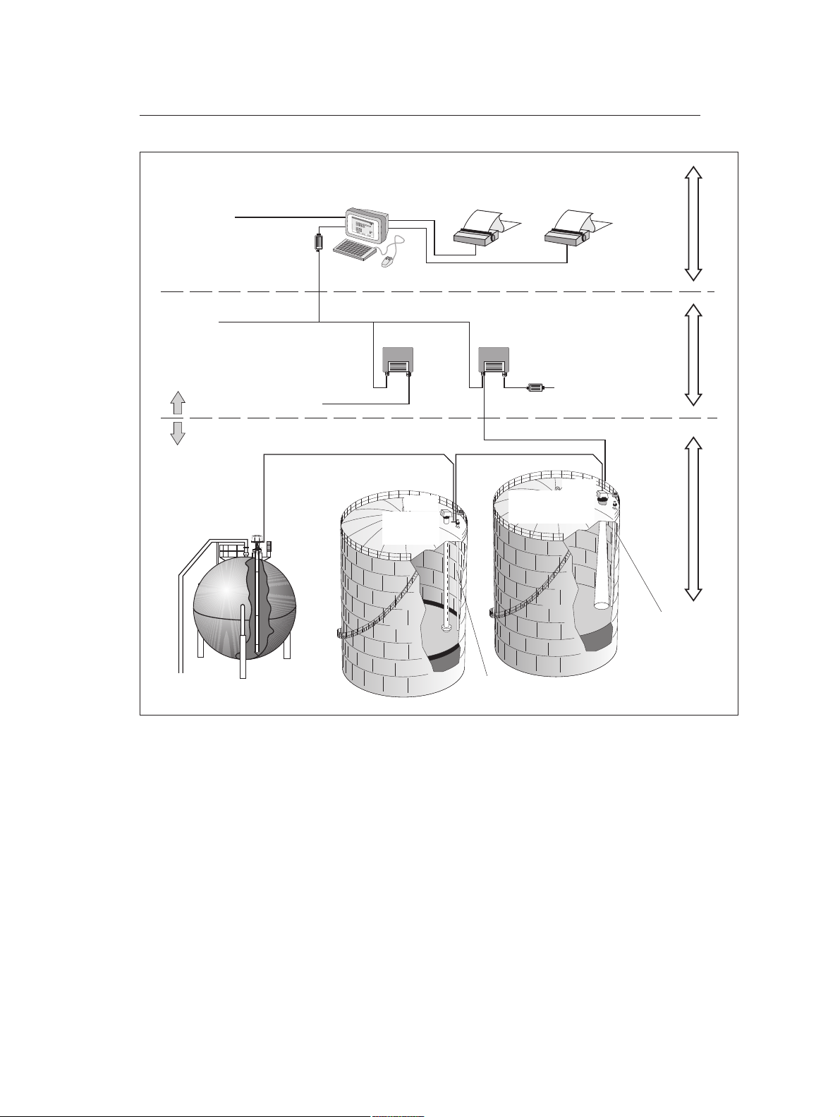
Figure 1-1. General configuration of a TankRadar REX sys-
tem.
All the measured data is presented to the operator by the TankMaster
WinOpi, which in its complete version contains inventory functions. A
plant host computer can be connected for further processing of data.
All Rosemount Tank Gauging supplied parts for tank top mounting weigh
less than 25 kg (55 lb.) (except for pressure flange etc. for the LPG/LNG
Gauge). This makes it possible for one man to carry the various
TankRadar parts to the tank top for installation.
Please read the Technical Description for a more detailed description of
the Rosemount TankRadar REX system.
REX_System_General.eps
1-2
Page 15

Installation
308014EN, Edition 4
May 2013
The basic parts of the Rosemount TankRadar REX System are:
• The Radar Tank Gauge, RTG, is an intelligent explosion pro-
• The Data Acquisition Unit, DAU, is used for measuring tempera-
• The Field Communication Unit, FCU, acts as a gateway and
• The Field Bus Modem, FBM, is a converter between RS-232C
Rosemount Tank Radar REX
Chapter 1 Introduction
tected instrument for measuring the level of a product inside a
tank. Four different Tank Connection Units can be attached in
order to satisfy a variety of different applications.
The RTG 3900 is equipped with auxiliary inputs such as temperature sensor inputs and analog inputs. The RTG 3900 also features
two relay outputs.
ture and can, as an option, be equipped with a Local Readout Display (LCD) for presentation of measured values.
data concentrator between the Group Bus and the Field Bus. Each
FCU can have a total of 32 RTGs and 32 DAUs connected to it.
and the TRL/2 Bus. It is used for connecting a PC with TankMaster to the TRL/2 Bus.
• The TankMaster WinOpi is the operator´s interface for the REX
system. The WinOpi is used for setting up a REX system with
alarm handling, batch reports, automatic report handling, historical
data sampling and inventory calculations.
• The TankMaster WinSetup is a software for configuration, calibration and service of a REX System.
1-3
Page 16

Rosemount Tank Radar REX
Chapter 1 Introduction
1.1 Manual Overview
This manual provides information about mechanical and electrical
installation of Rosemount TankRadar REX equipment. It covers the
TankRadar REX 3900 series of transmitters, and also provides
instructions for TRL/2 Data Acquisition Units, Field Communication Units
and Field Bus Modems.
Chapter 1 provides an overview of the
Rosemount TankRadar REX radar gauging system.
Chapter 2 gives a brief description of safety concepts and
European ATEX Directive information.
Chapter 3 describes the 3900 transmitter head and the cor-
responding antennas.
Chapter 4 describes the Data Acquisition Unit in the
TankRadar REX system.
Installation Manual
308014EN, Edition 4
May 2013
Chapter 5 describes the Display Unit RDU 40.
Chapter 6 describes the Field Communication Unit (FCU).
Chapter 7 describes Bus Modems used for communication
between a workstation and a TankRadar REX level gauging
system.
Chapter 8 describes various types of Junction Boxes that
can be used to connect different system units.
Chapter 9 provides information on how to connect a
TankRadar REX system to a host computer system.
Chapter 10 describes how to assemble the various gauge
types and how to mount them on a tank.
Chapter 11 describes electrical installation of the
TankRadar REX gauge system.
Chapter 12 describes installation of sub-supplier equipment
used in the TankRadar REX system.
Chapter 13 provides a list of installation drawings.
Chapter 14 provides technical data for the different REX
units.
1-4
Page 17

Installation Manual
308014EN, Edition 4
May 2013
2. Safety
Rosemount TankRadar REX equipment is often used in areas where
flammable materials are handled and where an explosive atmosphere
may be present. To protect both the plant and the personnel, precautions
must be taken to ensure that this atmosphere cannot be ignited. These
areas are called hazardous areas and equipment within these areas
must be explosion protected.
A number of different explosion protection techniques have been
developed over the years. Intrinsic safety and explosion proof (or flame
proof) safety are two techniques.
2.1 Intrinsic Safety
Intrinsic safety, IS, is based on the principle of restricting electrical
energy available in hazardous-area circuits such that any sparks or hot
surfaces, that may occur as a result of electrical faults in components,
are unable to cause ignition. Intrinsic safety is the only technique
accepted for Zone 0 hazardous areas. It is also safe for personnel and
allows equipment to be maintained without the need for a gas-free
certificate.
Rosemount Tank Radar REX
Chapter 2 Safety
For example, temperature measurement with the DAU is intrinsically
safe.
The basic principles of intrinsic safety are:
• All flammable materials are grouped according to the energy
needed to ignite them.
• Equipment located in hazardous areas are classified according to
the maximum surface temperature that it can produce and this
must be safe with the flammable gases that may be present.
• Hazardous areas are classified according to the probability that an
explosive atmosphere is present, and this dictates whether or not
a particular explosion protection technique may be used.
Note! For trouble shooting and repair work of components in or in connection
to intrinsically safe equipment, strict observance of the following rules is
necessary:
- Disconnect the power supply to the Radar Tank Gauge.
- Use a certified battery operated instrument only.
- Use Rosemount TankRadar REX original spare parts only.
Replacement with non-original spare parts may jeopardize the intrinsic
safety.
2-1
Page 18

Installation Manual
Rosemount Tank Radar REX
Chapter 2 Safety
308014EN, Edition 4
2.2 Explosion Proof
Explosion proof enclosures can be used when an explosion can be
allowed inside the enclosure as long as it does not spread to the outside.
The enclosure must be strong enough to withstand the pressure and
must have narrow gaps to allow the pressure to escape without igniting
the atmosphere outside of the equipment.
Note! Any substitution to non-recognized parts may impair safety.
The explosion-proof (flame-proof) enclosure of the Transmitter Head
must not be opened while the unit is powered.
May 2013
2-2
Page 19
Installation Manual
308014EN, Edition 4
May 2013
2.3 European ATEX Directive Information
2.3.1 Radar Unit
The REX Radar Unit has been certified to comply with Directive 94/9/EC
of the European Parliament and the Council as published in the Official
Journal of the European Communities No. L 100/1.
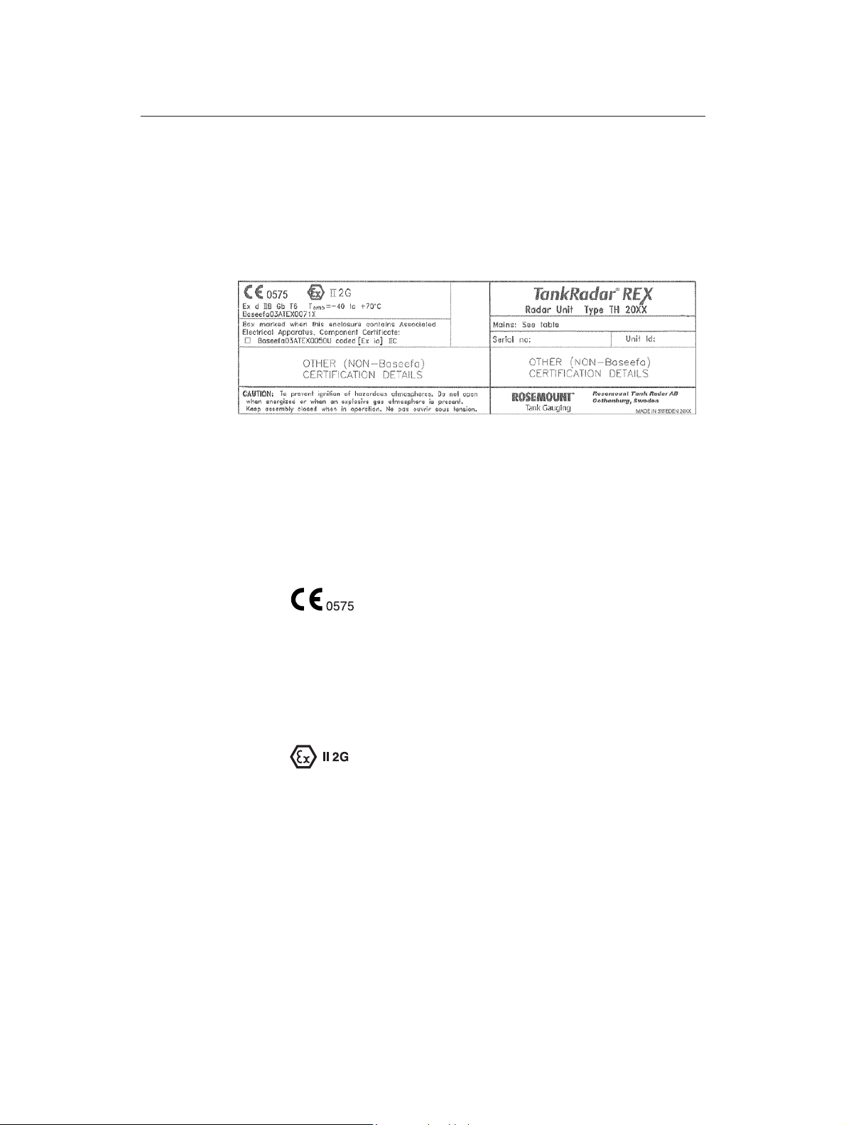
Figure 2-1. Certification label ATEX for the 2015 Radar Unit (used in
3900 series radar tank gauges).
Rosemount Tank Radar REX
Chapter 2 Safety
The following information is provided as part of the label of the radar unit:
• Name and address of the manufacturer
(Rosemount Tank Radar AB).
• CE Conformity Marking
• Complete model number
• The serial number of the device
• Year of construction
• Marking for explosion protection:
• Ex d IIB Gb T6 (-40 °C Ta +70 °C)
• Baseefa(2001) ATEX certificate number: Baseefa03ATEX0071X
Special Conditions for Safe Use (X):
• The Type TH2015-2019 Radar Units are not to be mounted
directly on to a tank.
• For replacement purposes the cover fastening screws are to be of
minimum grade A4-80 stainless steel.
• The permanently attached cables are to be suitably terminated
and protected against impact.
2-3
Page 20
Rosemount Tank Radar REX
Chapter 2 Safety
2.3.2 Radar Tank Gauge
The 3900 Radar Tank Gauge (type TH2015-2019 Radar Unit with
antenna certified for Zone 0) has been certified to comply with Directive
94/9/EC of the European Parliament and the Council as published in the
Official Journal of the European Communities No. L 100/1.
The 3900 series of Radar Tank Gauges is intended to be mounted
directly on tank.
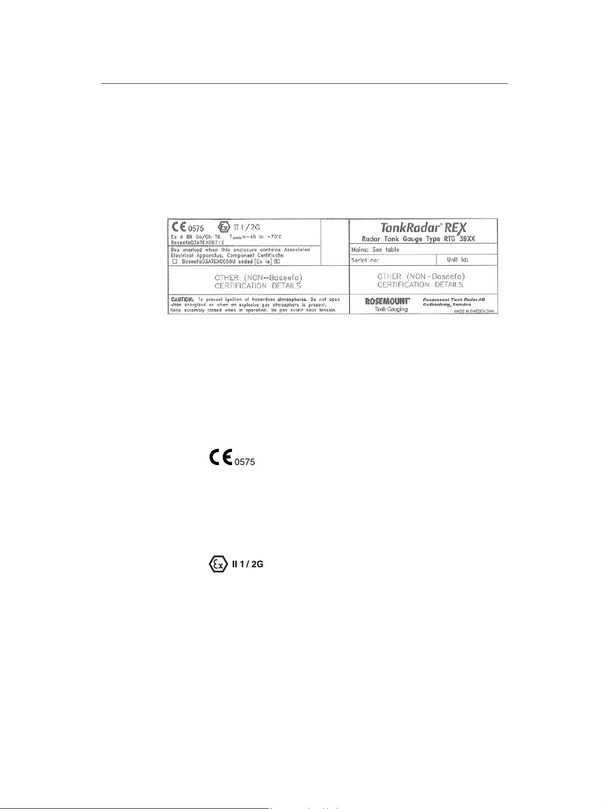
Figure 2-2. Certification label ATEX for the 3900 Series Radar Tank
Installation Manual
308014EN, Edition 4
May 2013
Gauge.
The following information is provided as part of the label of the radar tank
gauge:
• Name and address of the manufacturer
(Rosemount Tank Radar AB).
• CE Conformity Marking
• Complete model number
• The serial number of the device
• Year of construction
• Marking for explosion protection:
• Ex d IIB Ga/Gb T6 (-40 °C Ta +70 °C)
• Baseefa(2001) ATEX certificate number: Baseefa03ATEX0071X
Special Conditions for Safe Use (X):
• For replacement purposes the cover fastening screws are to be of
minimum grade A4-80 stainless steel.
2-4
• The permanently attached cables are to be suitably terminated
and protected against impact.
Page 21

Installation Manual
308014EN, Edition 4
May 2013
2.3.3 Transmitter Interface Card (TIC)
Figure 2-3. Certification label for the Transmitter Interface Card (TIC).
The Transmitter Interface Card (TIC) is mounted within the flameproof
enclosure. It is required for intrinsically safe inputs such as 4-20 mA
current loops and local display unit.
The following information is provided as part of the label of the TIC:
Rosemount Tank Radar REX
Chapter 2 Safety
• Name and address of the manufacturer
(Rosemount Tank Radar AB)
• CE Conformity Marking:
• Year of construction
• Marking for explosion protection:
• [Ex ia] IIC (Ga) (-40 °C Ta +85 °C)
• Baseefa(2001) ATEX EC-Type Examination Certificate number:
Baseefa03ATEX0050U
Schedule of Limitations
• The Transmitter Interface Card must be housed within an enclosure which provides a degree of protection of at least IP20.
• The 0V connections must be interconnected and connected to an
I.S. earth point in accordance with EN60079-14 12.2.4., when the
component is installed within an assembly.
• The arrangements for the connections to non-hazardous area and
hazardous area external circuits must comply with the requirements of Clause 6.3 of EN 50020:2002.
Note! For electrical (I.S.) parameters refer to the appended EC-Type
Examination Certificate Baseefa03ATEX0050U.
2-5
Page 22
Rosemount Tank Radar REX
Chapter 2 Safety
2.3.4 Temperature Multiplexer Card (TMC)
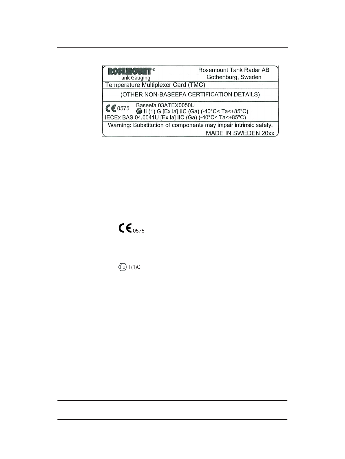
Figure 2-4. Certification label for the Temperature Multiplexer Card
The Temperature Multiplexer Card (TMC) is mounted within the
flameproof enclosure. It is used for connecting up to 6 temperature
sensors to the REX 3900 gauge.
The following information is provided as part of the label of the TMC:
Installation Manual
308014EN, Edition 4
May 2013
(TMC).
• Name and address of the manufacturer
(Rosemount Tank Radar AB)
• CE Conformity Marking:
• Year of construction
• Marking for explosion protection:
• [Ex ia] IIC (Ga) (-40 °C Ta +85 °C)
• Baseefa(2001) ATEX EC-Type Examination number:
Baseefa03ATEX0050U
Schedule of Limitations
• The Temperature Multiplexer Card must be housed within an
enclosure which provides a degree of protection of at least IP20.
• The 0V connections must be interconnected and connected to an
I.S. earth point in accordance with EN60079-14 12.2.4., when the
component is installed within an assembly.
• The arrangements for the connections to non-hazardous area and
hazardous area external circuits must comply with the requirements of Clause 6.3 of EN 50020:2002.
Note! For electrical (I.S.) parameters refer to the appended EC-Type
Examination Certificate Baseefa03ATEX0050U.
2-6
Page 23
Installation Manual
308014EN, Edition 4
May 2013
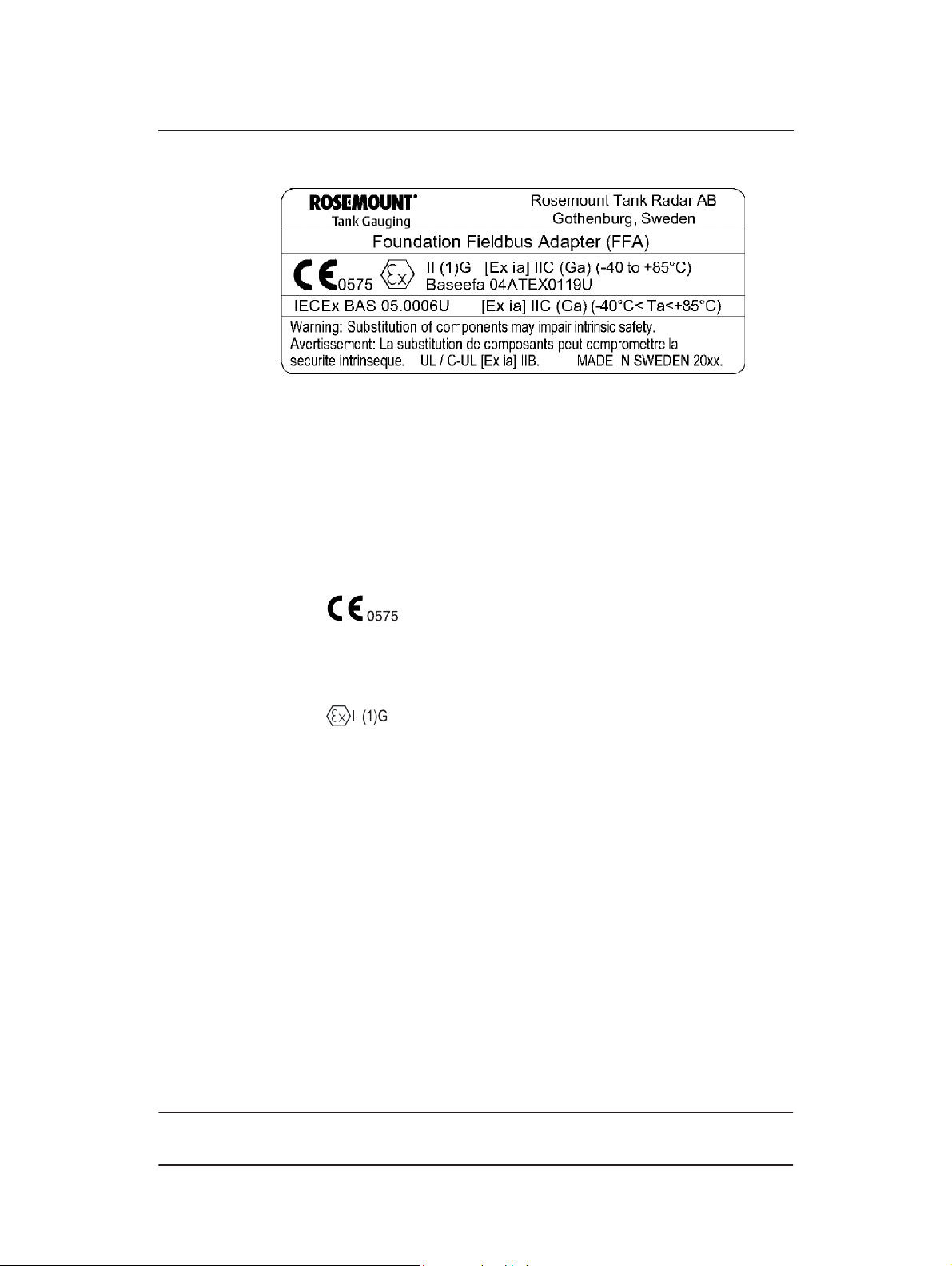
2.3.5 FF Adaptor Card (FFA)
Figure 2-5. Certification label for the FF Adaptor Card (FFA).
The FF Adaptor card (FFA) is mounted within the flameproof enclosure.
It is, in conjunction with a Fieldbus Communication Board
(BAS01ATEX1385U), used to interface to an intrinsically safe Fieldbus.
The following information is provided as part of the label of the FFA:
• Name and address of the manufacturer
Rosemount Tank Radar REX
Chapter 2 Safety
(Rosemount Tank Radar AB)
• CE Conformity Marking:
• Year of construction
• Marking for explosion protection:
• [Ex ia] IIC (Ga) (-40 °C Ta +85 °C)
• Baseefa(2001) ATEX EC-Type Examination Certificate number:
Baseefa04ATEX0119U
Schedule of Limitations
• The FF Adaptor Card must be housed within an enclosure which
provides a degree of protection of at least IP20. If the FF Adaptor
Card is mounted within a hazardous area it must be installed
within an appropriately certified flameproof enclosure.
• The arrangements for the connections to non-hazardous area and
hazardous area external circuits must comply with the requirements of Clause 6.3 of EN 50020:2002.
• The FF Adaptor Card is considered to be suitable for use within
EEx d apparatus with an Ambient Temperature range of
(-40 °C Ta +85 °C).
Note! For electrical (I.S.) parameters refer to the appended EC-Type
Examination Certificate Baseefa04ATEX0119U.
2-7
Page 24
Rosemount Tank Radar REX
Chapter 2 Safety
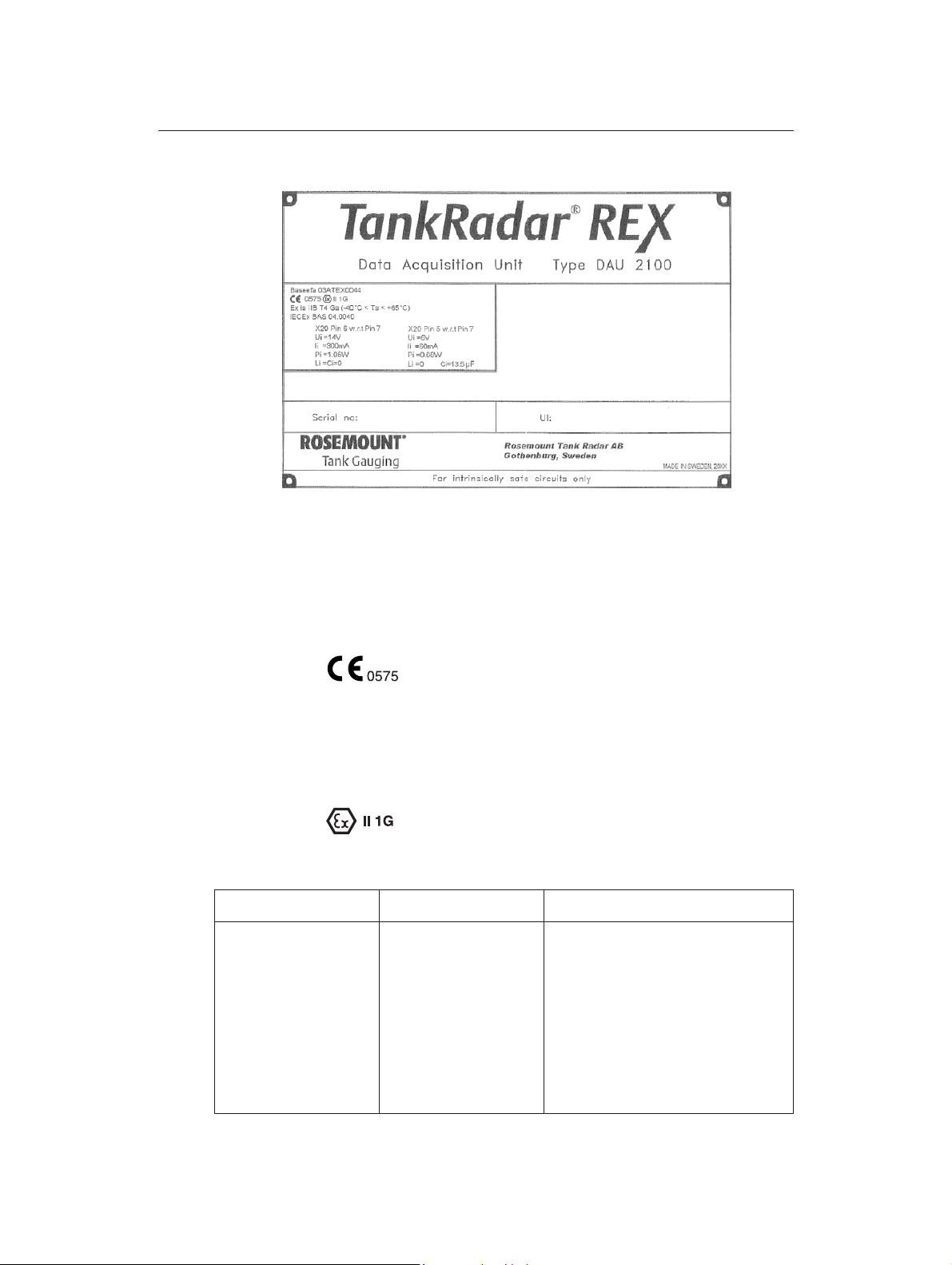
2.3.6 Data Acquisition Unit (DAU)
Figure 2-6. Certification label ATEX for the Data Acquisition Unit.
Installation Manual
308014EN, Edition 4
May 2013
The following information is provided as part of the label of the Data
Acquisition Unit (DAU):
• Name and address of the manufacturer
(Rosemount Tank Radar AB)
• CE Conformity Marking
• Complete model number
• The serial number of the device
• Year of construction
• Marking for explosion protection:
• Ex ia IIB T4 Ga (-40 °C Ta +65 °C)
X20 Pin 6 w.r.t Pin 7 X20 Pin 5 w.r.t Pin 7 X21 (For connection of up to 14 RTDs)
Ui=14 V
Ii=334 mA
Pi=1.17 W
Li=Ci=0
Ui=6 V
Ii=60 mA
Pi=0.08 W
Li=Ci=0
U0=6 V
I0=394 mA
P0=1.25 W
Ui=1.2 V
Ii=10 mA
Pi=0.02 W
Li=0
Ci=13.5 F
2-8
• Baseefa(2001) ATEX EC-Type Examination Certificate number:
Baseefa03ATEX0044
Page 25
Installation Manual
308014EN, Edition 4
May 2013
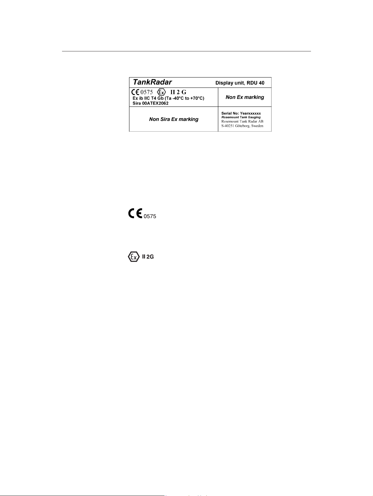
2.3.7 Remote Display Unit 40 (RDU 40)
Figure 2-7. Approval label for the Remote Display Unit RDU40.
The following information is provided as part of the label of the Remote
Display Unit 40 (RDU 40):
• Name and address of the manufacturer
• CE Conformity Marking:
Rosemount Tank Radar REX
Chapter 2 Safety
(Rosemount Tank Radar AB).
• Year of construction
• Marking for explosion protection:
• Ex ib IIC T4 Gb (-40 °C Ta +70 °C)
• Sira ATEX certificate number: Sira 00 ATEX 2062
The following instructions apply to equipment covered by certificate
number Sira 00ATEX2062:
1 The equipment may be used with flammable gases and vapours
with apparatus groups IIC, IIB and IIA and with temperature
classes T1, T2, T3 and T4.
2 The equipment is only certified for use in ambient temperatures in
the range -40 °C to +70 °C and should not be used outside this
range.
3 Installation shall be carried out in accordance with the applicable
code of practice.
4 Repair of this equipment shall be carried out in accordance with
the applicable code of practice.
5 Certification marking as detailed in drawing number 9150 074-
980.
2-9
Page 26

Rosemount Tank Radar REX
Chapter 2 Safety
Installation Manual
308014EN, Edition 4
May 2013
2-10
Page 27
Installation Manual
308014EN, Edition 4
May 2013
3. Description of 3900 REX
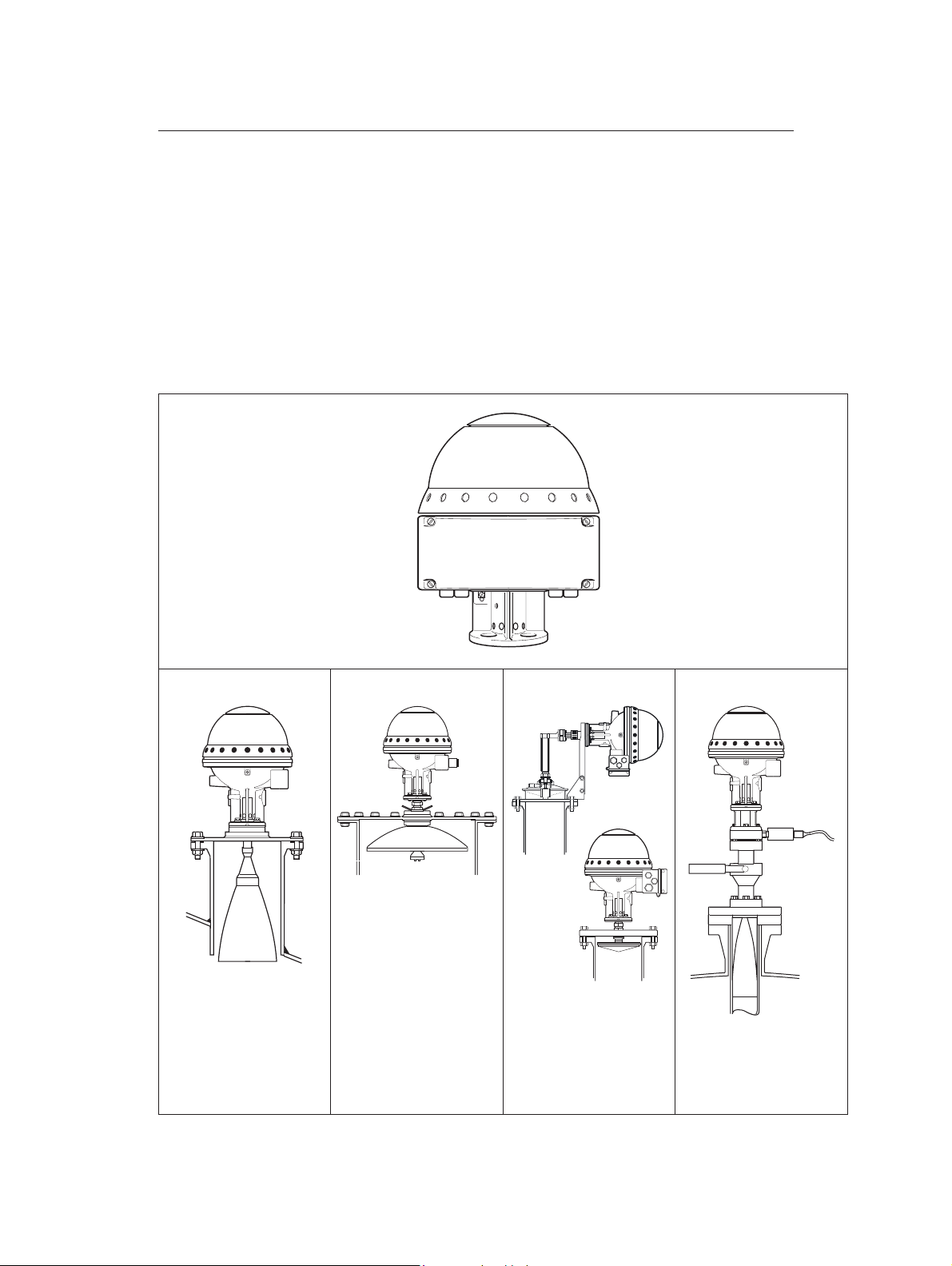
3.1 Transmitter Head RTG 3900 REX
Depending on the type of tank connection unit that the transmitter head
is mounted on, there are four types of Radar Tank Gauges. The
transmitter head contains all the electronics for signal processing,
communication and connection of external sensors. The RTG 3900
transmitter head is used on all the gauge types 3920 - 3960.
Rosemount Tank Radar REX
Chapter 3 Description of 3900 REX
RTG 3920 RTG 3930 RTG 3950 RTG 3960
The Horn Antenna
Gauge for fixed roof
installation without still
pipe.
The Parabolic
Antenna Gauge for
demanding environments without still pipe.
The Still Pipe Gauge
for measuring in still
pipes.
The LPG/LNG Gauge
for liquid gas, LPG and
LNG.
3900_TH.eps
Figure 3-1. The RTG 3900 gauge can use different antennas.
3-1
Page 28
Rosemount Tank Radar REX
Chapter 3 Description of 3900 REX
3.1.1 Transmitter Head Electronics
The electronics is mounted in an exchangable unit in the explosion proof
Transmitter Head. A high measurement accuracy is achieved by using
digital reference circuitry, and by controlling the internal temperature by
an internal heater.
The 3900 transmitter head can be used on all types of TRL/2 antennas.
A metrological seal is available to prevent unauthorized changes of
database settings.
Some of the electronic cards shown below are optional and may not be
installed in your transmitter.
Installation Manual
308014EN, Edition 4
May 2013
Transmitter Rectifier Card
3
1
2
4
1. X12. Intrinsically safe connec-
2. X11. Non-intrinsically safe con-
3. Electronic unit.
4. Ground connection.
Field Communication Card
Signal Processing Card
Analog Processing Card
Transmitter Interface Card
Temperature Multiplexing
Motherboard
tion for auxiliary inputs such as
Slave DAU/RDU, temperature
sensors and analog inputs.
nection for power, communication and relays.
REX3900_TH_Electronics.eps
3-2
Figure 3-2. RTG 3900 transmitter head electronics.
Page 29

Installation Manual
308014EN, Edition 4
May 2013
3.1.2 Analog Processing Card - APC
The APC is used for filtering and multiplexing of analog input signals. By
keeping the analog circuitry on a separate card a high Signal to Noise
Ratio is achieved.
3.1.3 Transmitter Interface Card - TIC
The Transmitter Interface Card (TIC) is required for intrinsically safe
auxiliary inputs. The TIC includes:
• Two supply zener barriers and two return zener barriers for 4-20
• One supply zener barrier for a Slave Data Acquisition Unit or a
• Signal/supply connection for optional Temperature Multiplexer
Rosemount Tank Radar REX
Chapter 3 Description of 3900 REX
mA current loops.
Remote Display Unit.
Card (TMC).
3.1.4 Temperature Multiplexer Card - TMC
The Temperature Multiplexer Card (TMC) is used to connect up to 6
temperature sensors. Both spot and average sensors are supported.
3.1.5 Relay Output Card - ROC
The Relay Output Card (ROC) contains two relays. It allows controlling
external devices such as valves, pumps, heating coils, overfill protection
according to TÜV etc.
3.1.6 Field Communication Card - FCC
The Field Communication Card (FCC) handles communication with
external devices. There are different versions of the FCC card allowing
you to use various types of communication protocols and even emulate
other types of gauges.
3-3
Page 30
Rosemount Tank Radar REX
Chapter 3 Description of 3900 REX
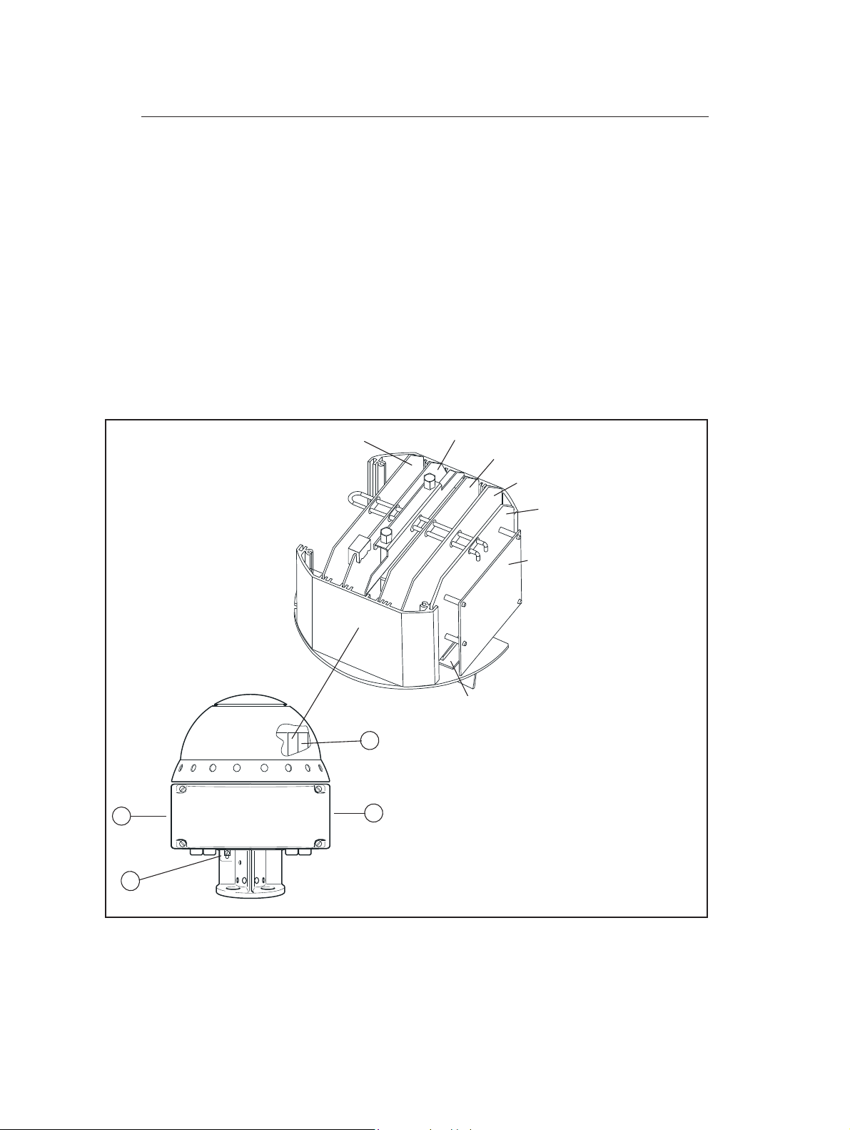
3.1.7 Metrological Seal
A switch on the FCC board can be used to prevent unauthorized
changes in the RTG database. The switch can be sealed in the writeinhibit position by using a special plastic cover.
Internal switch
Metrological Seal
Installation Manual
308014EN, Edition 4
May 2013
TH_Top.eps
Figure 3-3. RTG 3900 transmitter head with metrological seal.
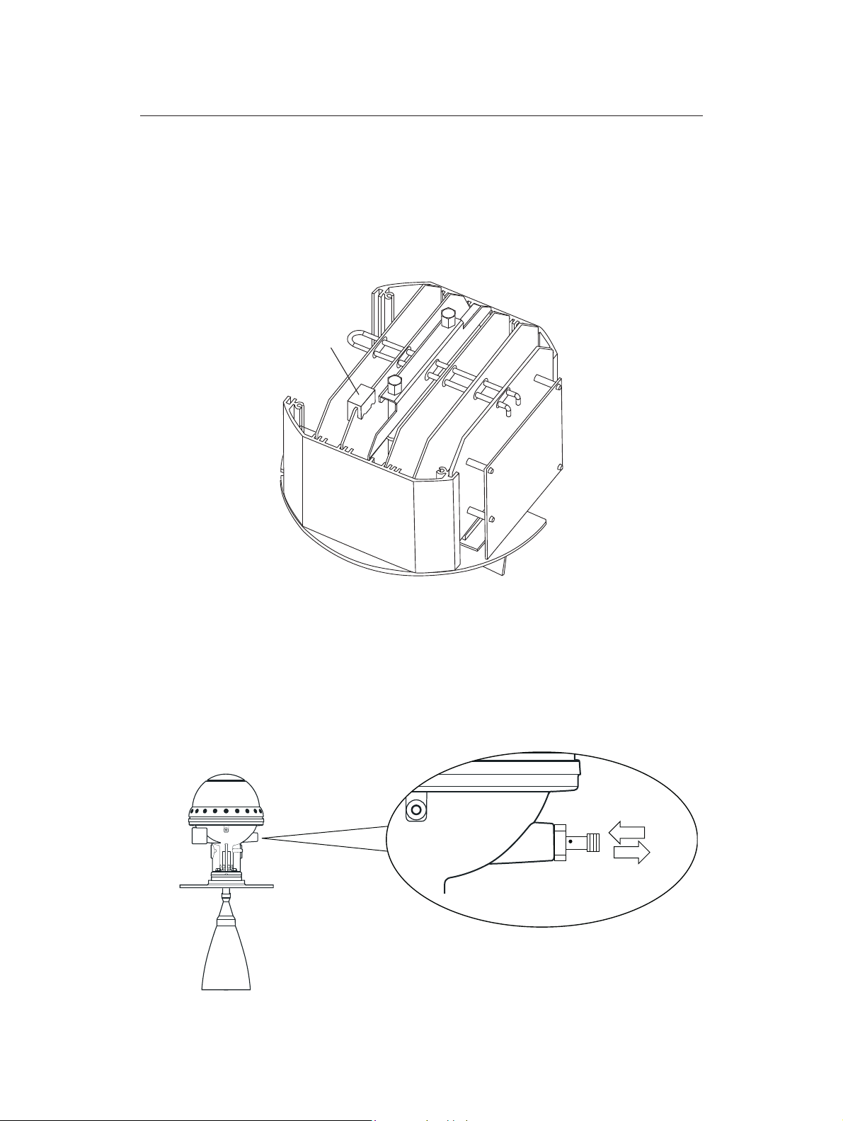
External switch
REX can also be equipped with an external metrological seal. It consists
of a rod which is connected to a write protection switch inside the
transmitter head. The rod can be sealed.
Write enable
Write inhibit
WriteProtect.eps
3-4
Figure 3-4. RTG 3900 transmitter head with metrological seal.
Page 31

Installation Manual
308014EN, Edition 4
May 2013
3.2 Antenna Types
Rosemount Tank Radar REX
Chapter 3 Description of 3900 REX
Weather
Protection
Hood
Transmitter
Head
Tank Nozzle
Min. 8"
Horn
Antenna
Figure 3-5. The RTG 3920 Horn Antenna Gauge
Weather
Protection
Hood
Transmitter
Head
0.75 m
Parabolic
Reflector
Figure 3-6. The RTG 3930 Parabolic
Antenna Gauge
0.44 m
Antenna Feeder
The Horn Antenna Gauge,
RTG 3920
The Horn Antenna Gauge is
designed for an 8” antenna to be
used in small size openings on tanks
with fixed roofs.
The RTG 3920 is designed for measurement of a variety of oil products
and chemicals. However, for bitumen/asphalt and similar products the
Parabolic antenna is recommended.
The Parabolic Antenna Gauge,
RTG 3930
The Parabolic Antenna Gauge measures level of all types of liquids, from
light products to bitumen/asphalt.
The gauge is designed for mounting
on tanks with fixed roofs and has
custody transfer accuracy.
The design of the parabolic antenna
provides extreme tolerance against
sticky and condensing products. The
narrow beam of this antenna makes
it very suitable in narrow tanks with
internal structures.
3-5
Page 32

Rosemount Tank Radar REX
Chapter 3 Description of 3900 REX
Waveguide
Unit
0.5 m
Figure 3-7. The RTG 3950 Still Pipe Gauge
0.59 m
Antenna
Weather
Protection
Hood
Installation Manual
308014EN, Edition 4
May 2013
The Still Pipe Gauge, RTG 3950
The Still Pipe Gauge is used on tanks
with still pipes and with all products
suited for still pipes.
The gauge uses a low-loss radar
propagation mode which virtually
eliminates the influence of the still
pipe condition. Measurement is
made with highest accuracy even
when the pipe is old, rusty and covered with deposits.
0.7 m
The Still Pipe Gauge fits 5”, 6", 8",
10" and 12" pipes. It can be mounted
on an existing still pipe and there is
no need to take the tank out of operation during installation.
There are two versions of RTG 3950:
fixed and inclined. The inclined version has a hinged hatch, enabling full
pipe size product sampling or verification hand-dips.
0.3 m
Transmitter
Head
Housing
1.0 m
Lower Flange
6" Existing
pressure vessel
flange
Figure 3-8. The RTG 3960 LPG/LNG
Antenna Gauge
Weather
Protection
Hood
Pressure
Transducer
Valve
Pipe Cone
4" or Ø 100 mm
Still Pipe
The LPG/LNG Gauge, RTG 3960
The RTG 3960 is designed for level
measurements in LPG and LNG
tanks. A 4” still pipe is used as a
wave guide for the measurement and
prevents a wavy or boiling surface
from disturbing the measurement.
Radar signals are transmitted inside
the pipe towards the surface.
The pressure sealing is a quarts window approved for use in pressure
vessels. As standard the gauge is
also equipped with a fire-proof block
valve and a vapor space pressure
sensor.
The LPG/LNG Gauge is available in
two versions, a 150 PSI version and
a 300 PSI version.
The reference pin function enables
verification of measurement without
opening the tank. By setting the
gauge into “test mode” the measured
distances are compared with the
actual distances.
3-6
Page 33

Installation Manual
308014EN, Edition 4
May 2013
Chapter 4 The Data Acquisition Unit
4. The Data Acquisition Unit
The Data Acquisition Unit (DAU) is a complement to the Radar Tank
Gauge (RTG) to interface various sensors for temperature
measurement.
The DAU is intrinsically safe and is connected to the RTG on the same
tank. It receives its power supply from and communicates via the
Transmitter Interface Card (TIC) in the RTG.
LCD display for
local readout
0.28 m (11”)
Rosemount Tank Radar REX
0.23 m (9”)
Figure 4-1. The Slave Data Acquisition Unit.
4.1 Local Readout Display
The DAU can as an option be equipped with a Local Readout Display
showing the product level as well as the parameters measured by the
DAU itself.
Cable glands (not for US market)
SDAU_2100.eps
4-1
Page 34

Rosemount Tank Radar REX
Chapter 4 The Data Acquisition Unit
4.2 Write Enable/Inhibit Switch
The DAU is equipped with a switch that can be used to prevent
unauthorized changes in the database (EEPROM).
In order to enable programming of the EEPROM, the S1 switch must be
set in the position, towards the block terminals. The switch can be locked
and sealed in the write inhibit position using a wire through the clevis
pins.
WRITE INHIBIT SWITCH S1
Installation Manual
308014EN, Edition 4
May 2013
DAU
Figure 4-2. The write enable/inhibit switch.
DAU_WriteInhibit.eps
4-2
Page 35

Installation Manual
308014EN, Edition 4
May 2013
Rosemount Tank Radar REX
Chapter 4 The Data Acquisition Unit
4.3 Connecting the Data Acquisition Unit, DAU 2100
Instructions for connection of the Data Acquisition Unit is given on the
inside of its cover.
4.3.1 Power Supply
The Data Acquisition Unit receives its power via the local line from the
associated Radar Tank Gauge. If the distance between the Transmitter
Head and the Data Acquisition Unit is longer than 2.0 m, a junction box
must be used to connect an extension cable. This extension cable must
not be longer than 50 m. For safety reasons the ends of the unused
wires must be properly insulated and terminated. The junction box can
either be customer supplied or supplied by Rosemount Tank Gauging as
an option, see chapter 8.
4.3.2 Temperature Sensors
Under the lid of the Data Acquisition Unit there are instructions printed as
to how to connect the sensors and transducers.
Connect
temperature
sensors.
DAU_Tempsens_Connect.eps
Connect Reference
Resistor to terminals
43, 44 and 45.
Figure 4-3. The X21 terminal for temperature sensor connec-
tions.
Either Pt 100 (spot element) or Cu 100 (averaging sensor) temperature
sensors can be used. If the sensors are connected with common return
wires then jumpers must be connected in the Data Acquisition Unit
terminals.
Intrinsically safe connection of the temperature sensors, the RTDs, is
made with n + 2 wires for an n-element spot or averaging sensor. There
are spot elements with three wires for each element. The DAUs can
connect up to 14 RTDs (Resistance Temperature Detectors) on the X21
terminal on the motherboard.
4-3
Page 36

Rosemount Tank Radar REX
Chapter 4 The Data Acquisition Unit
4.3.3 Selecting the temperature range
A DAU can be configured for one of three different temperature ranges
by means of a multiplexer. The multiplexer for the RTDs has two different
amplification factors which are jumper selected. It is also possible to
provide an offset to the measured signal by adding a current to it.
Installation Manual
308014EN, Edition 4
May 2013
X1 - OPEN
X2 - OPEN
X3 - CLOSED
Figure 4-4. Selecting the temperature range.
The amplification is selected on the X1 and X2 sockets and the offset is
selected on the X3 according to table 11.3. The standard setting is from 50°C to +125°C. The database setting of the temperature range in the
TankMaster WinSetup must correspond to the setting of the jumpers.
Temperature Range
Pt 100
-50 to +125 °C OPEN OPEN CLOSED
-50 to +300 °C CLOSED CLOSED CLOSED
-200 to +150 °C CLOSED CLOSED OPEN
X1 X2 X3
Table 4-1. Temperature range settings.
A high precision reference resistor must be connected to the X21
terminal to positions 43, 44 and 45. Depending on the temperature range
stated in the Required System Information form, one out of three
different reference resistors is chosen and connected. See Figure 4-3
and the spare parts list in Rosemount TankRadar REX Service Manual.
DAU_TempRange.eps
4-4
Page 37

Installation Manual
308014EN, Edition 4
May 2013
Rosemount Tank Radar REX
Chapter 5 The Remote Display Unit
5. The Remote Display Unit RDU40
The Remote Display Unit 40 (RDU 40) is a robust display unit for outdoor
use in hazardous areas. If there are less than six temperature elements
per tank, the RDU 40 is the most cost-effective solution for field display.
In this case the temperature elements can be connected directly to the
TankRadar gauge (RTG). The display functions are software controlled
by the connected TankRadar gauge.
The RDU 40 is connected by a 3-wire cable up to 100 m (330 ft) from the
RTG. Up to two units can be connected to one TankRadar Rex gauge. It
displays calculated data, such as level, average temperature, volume,
signal strength, etc. The data can be displayed in lists or as single
values. The operator can set up a user-defined window where the most
useful information is presented. This window will be shown as the default
view. The RDU 40 can view up to six spot temperature elements
connected to a TankRadar Rex gauge.
See chapter 11.5.11 for more information on how to connect the RDU40
to the REX transmitter. See also the Display Unit RDU40 User´s Guide
for instructions on how to use the RDU40.
Level
.
2 x M20 M25
RDU40.eps, RDU40_REX.eps
LCD display 128 x 64 pixels
Level
.
Figure 5-1. RDU 40 connected to the REX gauge.
5-1
Page 38

Rosemount Tank Radar REX
Chapter 5 The Remote Display Unit
5.1 Installation
Unscrew and remove all six screws on the RDU40 cover. Remove the
cover and take care of the locking device for the weather protection
hatch.
The RDU 40 shall be connected to the TankRadar REX junction box for
cable connections.
Installation Manual
308014EN, Edition 4
May 2013
RDU40_install_master_slave.eps
Figure 5-2. Installation of RDU 40 master and slave
Any of the three cable glands may be used to take the cable into the
RDU40:
2xM20 - Cable diameter: 7 mm - 14 mm
1xM25 - Cable diameter: 9 mm - 18 mm.
External adapters 1/2 NPT and 3/4 NPT are optional.
Connect the RDU 40 to the X12 terminal in the REX junction box as
illustrated in Figure 5-2.
5-2
Page 39

Installation Manual
308014EN, Edition 4
May 2013
In order to allow proper operation and to fulfil EMC requirements, the
cable between the RDU 40 and the REX junction box should meet the
following requirements:
• Shielded cable. Minimum 3 wires. The shield shall be circular connected inside the cable gland of the RDU 40 and connected to
ground in the REX junction box.
• All wires must have at least 0.25 mm individual insulation.
• Maximum total length of 100 m, both master and slave included.
• Minimum AWG 20 or 0.5 mm² for each wire.
The RDU 40-chassi shall be grounded locally to the tank. Use minimum
4 mm² or AWG 11 wire. Additional protective ground connection to the
power distribution central or the REX junction box is not recommended
except where required according to national code of practice. A ground
loop with circulating current may occur.
Note! It is not possible to use an RDU40 and a SDAU simultaneously.
Rosemount Tank Radar REX
Chapter 5 The Remote Display Unit
If a cable with two shields is used, one shield shall be connected to
ground in the REX junction box and the other shall be circular connected
inside the cable gland of the RDU 40.
Figure 5-3. Back of RDU40.
Check the gasket and put the locking device for the weather protection
hatch in position when remounting the RDU-cover. Tighten all six screws
firmly.
Mount the RDU 40 with the four M4 screws. Distances between the
screws are 60 mm and 68 mm according to the drawing on the back of
the RDU 40.
See the RDU 40 User´s Guide, Ref. no. 308010E, for further
information on RDU 40 installation.
5-3
Page 40

Rosemount Tank Radar REX
Chapter 5 The Remote Display Unit
5.2 Two RDU 40 connected to the same REX
If two RDU 40 are connected to the same REX, one of them has to be
configured as “slave” while the other is “master”. The slave cannot be
configured or controlled individually but follows the master. Only the
LCD-contrast can be individually controlled on the slave RDU 40.
To make an RDU 40 work as a slave it is necessary to move the jumper
at the RDU 40 cover to position 2 (see Figure 5-2).
5.2.1 Data items
24 items are available, dependent of how the REX gauge is equipped:
• Level
• Ullage
• Level rate
Installation Manual
308014EN, Edition 4
May 2013
• Signal strength
• Volume
• Average temperature
• Temperature spot 1-6
• Analog input 1-2
• Vapour pressure
• Observed density
• Free water level
• Hart slave 1-3
• Relay 1-2
5-4
Page 41

Installation Manual
308014EN, Edition 4
May 2013
Rosemount Tank Radar REX
Chapter 6 The Field Communication
6. The Field Communication Unit
The Field Communication Unit (FCU) continuously polls data from the
Radar Tank Gauges and the Data Acquisition Units and stores it in a
buffer memory. The Field Communication Unit is the master on the Field
Bus but acts as a slave on the Group Bus.
Note! No explosion protection is provided, so the Field Communication Unit
must be installed in a non-hazardous area.
FCU_2160.eps
Ground
connection
Figure 6-1. The Field Communication Unit.
6.1 FCU Enclosure
As standard the Field Communication Unit is shipped in a weather
protected, wall-mounted box of the same type as the Data Acquisition
Unit. The Field Communication Unit is built on a Printed Circuit Board
and may be delivered as such for mounting within a customer supplied
enclosure.
Cable
outputs
6-1
Page 42

Rosemount Tank Radar REX
Chapter 6 The Field Communication Unit
6.2 Communication Ports
The Field Communication Unit has six connections for communication
interface boards, X1 to X6. The connections can be individually
configured as either Group Bus or Field Bus ports. There can be
maximum four Group Buses or four Field Buses at the same time.
Maximum configuration can be 2+4, 3+3 or 4+2 buses of each kind.
However, connections X5 and X6 are never configured as Field Bus
ports, while the X1 and X2 connections are never configured as Group
Bus ports.
As standard the Field Communication Unit is delivered with six FCM
interface boards for four Field Bus ports and two Group Bus ports.
The table below shows the maximum configurations of an extended
FCU:
Ports X1 X2 X3 X4 X5 X6
Installation Manual
308014EN, Edition 4
May 2013
Alternative 4+2
Alternative 3+3
Alternative 2+4
Table 6-1. Communication ports.
6.2.1 RS232 communication
There are two jumper connectors delivered with each unit. These can be
connected to the X5 and/or X6 for RS-232C Group Bus communication.
See Figure 6-2.
X4
X5
X6
FB FB FB FB GB GB
FB FB FB GB GB GB
FB FB GB GB GB GB
TRL/2 Bus
Interface boards,
FCM boards
X3
X2
X1
6-2
Jumper for
RS232C
FCU_BusPorts.eps
Figure 6-2. FCU Bus Ports
Page 43

Installation Manual
308014EN, Edition 4
May 2013
6.2.2 RS 485 communication
Each FCM interface board can be replaced with FCI interface boards for
RS-485 communication.
Note! The wire terminals 1 and 3 respectively 2 and 4 on FCM board connector
are parallel connected. See installation drawing.
Rosemount Tank Radar REX
Chapter 6 The Field Communication
6.3 Write Inhibit/Enable Switch
There is a write inhibit switch in the FCU that can be used to prevent
unauthorized changes in the FCU database. It can be locked in the write
inhibit position by securing a locking plate with a wire through the clevis
pins.
Write
enable
FCU_WriteEnableInhibit.eps
Write inhibit
Figure 6-3. Write inhibit/enable switch.
Reset switch
115 V
230 V
6-3
Page 44

Installation Manual
Rosemount Tank Radar REX
Chapter 6 The Field Communication Unit
308014EN, Edition 4
6.4 Connecting the Field Communication Unit, FCU 2160
6.4.1 Power Supply
There is a switch to select the supply voltage to either 115 V or 230 V.
Check that the switch is set in the right position before power is
connected. The switch is set to 230 V as standard.
If the switch is set to 115 V, mark the check-box on the nameplate: “Mark
box if re-wired for 115 VAC”:
May 2013
FCU_2160_Label.eps
Figure 6-4. FCU marking for 115 VAC.
Note! Do not turn the switch all the way around as it may damage the switch.
30
11
FCU_Power.eps
Figure 6-5. Selecting the FCU power supply voltage.
6.4.2 Connection to a PC
The FCU can be connected to the PC either directly via RS-232C or via a
Field Bus Modem (FBM) on the TRL/2 Group Bus.
6-4
The TRL/2 Bus requires a twisted and shielded pair with an area of min
0.50 mm2 (AWG 20 or similar). See chapter 11.2.
The RS-232C connection can be made with 3 wires from the PC to the
Field Communication Unit. The area must be at least 0.25 mm2 (AWG 24
or similar). The maximum length of the RS-232C connection is 30 m.
Page 45

Installation Manual
308014EN, Edition 4
May 2013
6.5 Redundancy
In order to reduce the risk of communication failure between the
TankMaster and the units connected to the TRL/2 fieldbus, two FCUs
can be connected to run in parallel to provide automatic redundancy. The
FCUs are connected with an extra cable allowing them to communicate.
The inactive FCU constantly checks if the connected FCU is active. If the
active FCU fails, it signals to the backup FCU to take over. Then the
backup FCU immediately switches to an active state. It is also possible
to use up to four TankMaster PC:s connected via different Group Buses.
FCU_redundant.eps
Rosemount Tank Radar REX
Chapter 6 The Field Communication
Redundant FCU:s.
Two FCU:s can be connected
in parallel. One of them is configured as the primary FCU and
the other as backup. The primary FCU is active. The
backup FCU listens to the communication on the Field Bus
and automatically takes over
the communication without any
action from the operator if the
primary FCU fails.
FCU_redundant_workstation.eps
Double FCU:s and
workstations.
With two FCU:s and two TankMaster workstations a complete redundancy from control
room to RTG is achieved.
6-5
Page 46

Rosemount Tank Radar REX
Chapter 6 The Field Communication Unit
Installation Manual
308014EN, Edition 4
May 2013
Local Area Network
FCU_redundant_FBM.eps
Redundant FCU:s, FBM:s and
workstations.
With two FBM:s safe communication between the TankMaster
workstation and the FCU is
achieved.
Several Group Buses.
An FCU can connect up to four
group buses. The buses can
have different masters like
TankMaster PC:s and DCS
units.
FCU_redundant_groupbus.eps
6-6
Page 47

Installation Manual
308014EN, Edition 4
May 2013
7. Bus Modems
Emerson Process Management/Rosemount Tank Gauging supplies two
types of modems (for technical details, please see chapter 14):
Field Bus Modem 2180: converts between USB or RS 232C and the
TRL/2 Bus. The TRL/2 protocol is used for communication with
Rosemount Tank Gauging equipment.
Rosemount Tank Radar REX
Chapter 7 Bus Modems
Figure 7-1. Field Bus Modem 2180
Enraf Bus Modem: converts between RS 232C and TRL/2 Bus or
RS 232C and Enraf GPU communication protocol.
Figure 7-2. Enraf Bus Modem
FBM2180_USB_Top_RosemounTG.eps
Modemb.eps
7-1
Page 48

Rosemount Tank Radar REX
Chapter 7 Bus Modems
7.1 Field Bus Modem 2180
7.1.1 DIN Rail Mounting
The FBM 2180 can be mounted on a DIN-rail 35 EN 50022. The
following is delivered with the FBM2180 kit:
• FBM 2180 TRL/2 Bus Modem
• Four screws
• Two DIN mounting clips
4 x
Installation Manual
308014EN, Edition 4
May 2013
1 Attach the two DIN rail
mounting clips to the back of
the FBM2180 by using the
four screws. There are four
holes drilled on the modem
housing to be used for the
clips.
20 mm
FBM2180_DIN_Rail.eps
FBM2180_DIN_Rail_Top.eps
15 mm 15 mm
2 Mount the FBM2180 on the
DIN rail and make sure that
the FBM2180 is securely
fastened.
7-2
Page 49

Installation Manual
308014EN, Edition 4
May 2013
7.1.2 Power Supply
Use adapter 90-264 V ac/9 V dc 1.5 A for RS232 communication.
DO NOT use external power supply when the modem is connected to
the USB port. The USB interface itself supports power to the FBM2180
modem.
Rosemount Tank Radar REX
Chapter 7 Bus Modems
FBM2180_Back.eps
7.1.3 TRL/2 Bus
Power supply (polarity independent)
(RS 232 communication only)
Figure 7-3. Power supply for RS232
Use single twisted preferably shielded pair cable. Individual shielding is
mandatory if parallel buses run in the same cable. Polarity independent.
Recommended wiring length:
Cable dimension Maximum Length
AWG 20 (0.50 mm2)
AWG 18 (0.75 mm2)
3000 m
4000 m
FBM2180_Back.eps
TRL/2 Bus
Figure 7-4. TRL/2 Bus terminal
7-3
Page 50

Rosemount Tank Radar REX
Chapter 7 Bus Modems
7.1.4 RS 232 Communication
The serial port on the FBM2180 fits to a standard M 9P Dsub connector.
Connect the modem to the COM port on the PC with a standard RS232
DTE-DCE cable (“straight” cable).
Installation Manual
308014EN, Edition 4
May 2013
RS 232 connector
FBM2180_Back / FBM2180_RS232_Top
RS 232 port
Figure 7-5. RS232 connection
7.1.5 USB Communication
For the USB port use cable type A>B. Do not use external power supply
when using the USB port. The USB interface itself supports power to the
FBM2180 modem.
USB connector
FBM2180_Back / FBM2180_USB_Top
7-4
USB port
Figure 7-6. USB connection
Page 51

Installation Manual
308014EN, Edition 4
May 2013
7.1.6 USB Driver Installation
The USB interface requires a Virtual COM Port driver. Rosemount
TankMaster version 4.F1 and higher fully supports Virtual COM Ports.
The driver is included on the Rosemount TankMaster CD version 4.F1
and higher.
To install the USB driver do the following:
1 Plug the USB cable into the FBM 2180 and to the USB port on the com-
puter. The Found New Hardware Wizard dialog for the FBM 2180 Serial
Converter will appear:
Rosemount Tank Radar REX
Chapter 7 Bus Modems
2 Follow the instructions on the screen for the FBM 2180 driver. The FBM
2180 drivers can be found on the installation CD for the Rosemount
TankMaster software. If you have the drivers on another location, choose
“Install from a list or specific location (Advanced)” and browse to the
folder where the drivers are located.
3 When the FBM 2180 driver installation is finished the Found New Hard-
ware Wizard dialog for the FBM 2180 Serial Port driver will appear:
Wizard_Welcome.TIF
Wizard_USB.TIF
7-5
Page 52

Rosemount Tank Radar REX
Chapter 7 Bus Modems
4 Follow the instructions on the screen for the FBM 2180 Serial Port driver.
5 If you are using Windows XP operating system, you will see the warnings
below appear during the USB driver installations:
Installation Manual
308014EN, Edition 4
May 2013
Wizard_Windows_XP / Wizard_Windows_XP_USB
6 Please click the Continue Anyway button. Our drivers are Microsoft
WHQL certified and work with the operating system.
7 Once the USB drivers are installed you are ready to use the FBM 2180.
7-6
Page 53

Installation Manual
308014EN, Edition 4
May 2013
7.1.7 Operation
Front Panel
The FBM 2180 front LEDs show information on power supply,
communication status and communication interface.
Rosemount Tank Radar REX
Chapter 7 Bus Modems
LEDs for external power
and communication
External power
RS232
USB
Gain
switch
Receive
Transmit
Termination
switch
Figure 7-7. FBM 2180 front panel
The Termination switch is used if there are extremely short cables
between the transmitter and the modem.
The Gain switch is set to Lo by default. This setting is sufficient in most
cases. The Hi Gain setting may be used if cable dimensions are
insufficient resulting in a heavily damped communication signal.
FBM2180_Front.eps
7.1.8 Communicating with TankMaster™
TankMaster WinSetup allows you to setup the communication between a
PC, Field Communication Unit (FCU) and field instruments in a
Rosemount Tank Gauging system. For each communication port that is
used on the PC a protocol channel has to be configured (see the
TankMaster WinSetup Reference Manual for more information on
communication protocol setup).
7-7
Page 54

Rosemount Tank Radar REX
Chapter 7 Bus Modems
7.1.9 USB Interface
The USB interface requires a Virtual COM Port driver. Virtual COM Ports
are supported by Rosemount TankMaster version 4.F1 or higher. See
“USB Driver Installation” on page 5. for more information.
In TankMaster™ WinSetup each FBM 2180 connected via a USB port is
displayed as a virtual COM port designated FBM 2180 Serial Port. For
each FBM 2180 a new Virtual COM Port is installed on the TankMaster
PC.
Virtual COM Port
for USB
communication
Installation Manual
308014EN, Edition 4
May 2013
Figure 7-8. Virtual COM port for USB interface
7.1.10 RS 232 Interface
For RS 232 communication simply connect to one of the COM ports on
the PC and select the corresponding port in the Master Protocol Channel
Configuration window:
COM Port
Figure 7-9. COM port configuration for RS232
TM_ProtocolConfig_FBM2180_b.TIF
MBMaster_ChannelConfig_COM1.TIF
7-8
Page 55

Installation Manual
308014EN, Edition 4
May 2013
7.1.11 Specifications
Rosemount Tank Radar REX
Chapter 7 Bus Modems
Explosion protection
Power supply (for RS-232)
Cable to Host PC
Field bus over voltage
protection
Field interface
Computer/Host interface
LED indicators
None
DC 7-12 V, max. 50 mA
RS-232: 3 m (10 ft)
USB: 3 m (10 ft)
Galvanic insulation, transient suppressors
TRL/2
RS-232 or USB
External power. Host connection TRL/2
transmit and receive
7-9
Page 56

Rosemount Tank Radar REX
Chapter 7 Bus Modems
7.2 Enraf Bus Modem, EBM
An Enraf Bus Modem (EBM) is used when configuring a Rex gauge for
Enraf emulation.
Entis / TankMaster
Installation Manual
308014EN, Edition 4
May 2013
Network
PLC
Enraf_Fieldbus_REX.eps
PC with WinSetup
software for
EBM
CIU
configuration of Rex
Rex gauge
Figure 7-10. A system where Enraf gauges have been replaced
by TankRadar Rex.
7-10
Page 57

Installation Manual
308014EN, Edition 4
May 2013
7.2.1 Connecting the Enraf Bus Modem
Rosemount Tank Radar REX
Chapter 7 Bus Modems
Field bus
connector
Modemb.eps
Modbus/Normal (Enraf) Switch
Modbus, left position
Enraf, right position
Figure 7-11. Connecting an Enraf Bus Modem (EBM).
7.2.2 Configuration
When an Enraf gauge is replaced with TankRadar Rex it is necessary to
configure the Rex gauge for emulation. Configuration is made with the
WinSetup software and requires an Enraf Bus Modem (EBM). How the
procedure is done depends on system type
System Type
Required Steps
(described below)
PC
connector
Baud rate Switch
2400, left position;
1200, right position most commonly used.
Optional Steps
(described below)
Standard System Step 1-2, 6-7 Step 3
Hybrid Step 1-4, 6-7
LPG Step 1-4, 6-7
Installation with
Step 1-2, 5-7 Step 3
Water Level Sensor
(WLS)
Table 7-2. Configuration procedure
7-11
Page 58

Installation Manual
Rosemount Tank Radar REX
Chapter 7 Bus Modems
Below follows a short configuration description. Details are described in
the Enraf Emulation Guideline (reference number 308013EN) and in
TankMaster WinSetup Reference Manual (reference number
303027EN).
Step 1 Connect the EBM.
Step 2 Configure the gauge in WinSetup.
Step 3 Install a tank in Winsetup: Required only for Hybrid / LPG systems
for which the analog inputs are used. However it is a good idea to
install a tank and associate a gauge to it, because then it is possible to benefit from the Open Tank View function.
Step 4 Configure the gauge by using the Hybrid Calculation window
(Hybrid
system) or LPG Setup window (LPG system) in Winsetup.
308014EN, Edition 4
May 2013
Step 5 Set holding registers for free water level measurements.
Step 6 Enter information into the Enraf Emulation window in WinSetup.
Set Enraf mode and move EBM switch from Modbus to Normal
(Enraf).
Step 7 Close Enraf Emulation window. The gauge now acts like an Enraf
instrument and the EBM can be disconnected. Connect the fieldbus to the CIU.
7-12
Page 59

Installation Manual
308014EN, Edition 4
May 2013
8. Junction Boxes
As optional equipment, a series of junction boxes can be delivered with
the TankRadar Rex system. They are used to connect the various
system units.
FCU
Rosemount Tank Radar REX
Chapter 8 Junction Boxes
Alternative connections
to DCS
system_JB
RTG with JBi
(section 8.1)
Temp.
Sensor
JB 36/42
(section 8.3)
JB
JB
Temp.
Sensor
DAU
RTG
JB
EEx e
(section 8.2)
Field
Bus
Modem
TankMaster PC
workstations in
network
Figure 8-1. Overview of the different junction boxes in a
TankRadar Rex system.
8.1 Integrated Junction Box, JBi
8.1.1 Explosion Approval
The integrated junction box is designed for increased safety classified
according to EEx e [ia] IIC T6. There is one EExe side for mains, bus
cables and relay outputs. The EExi side is for intrinsically safe
connections.
8-1
Page 60

Rosemount Tank Radar REX
Chapter 8 Junction Boxes
8.1.2 Design
• The box is sealed according to IP65.
• Temperature range is -40°C to +70°C (-40°F to +158°F).
8.1.3 Cable Inlets - RTG 3900
On the left-hand side (X12) there are two 1/2 in. and one 3/4 in. inlets.
There are 15 terminals for intrinsically safe cables to analog inputs, DAU
or Display Panel and up to 6 temperature sensors.
On the right-hand side (X11) there are two 3/4 in. and one 1/2 in. inlets.
The box has 8 terminals for power, communication signals and relay
outputs.
Installation Manual
308014EN, Edition 4
May 2013
JB_integrated
EEX i
Intrinsically safe side
Analog inputs
Temperature
sensors
DAU / RDU
Figure 8-2. RTG 3900 with Integrated Junction Box.
EEX e
Non-Intrinsically safe side
TRL/2 Bus
Analog outputs
Relay output
Power 230/115 VAC
8-2
Page 61

Installation Manual
308014EN, Edition 4
May 2013
Rosemount Tank Radar REX
Chapter 8 Junction Boxes
8.2 Junction Boxes for Intrinsically Safe and EEX e environments
JB 140-15
(EEX i)
JB_general_ed3
DAU / RDU
Cable
~ 2 m cable with
protective hose
~ 2 m cable
with
protective
hose
Figure 8-3. Intrinsically Safe and Explosion Proof Junction
Boxes.
JB 140-11
(EEX e)
5 x M25
TRL/2 Bus,
Analog
outputs,
Relay
output,
Power 230/
115 VAC
8.2.1 JB 140-15 for EEx i environments
JB 140-15 (EEx i) is used when a DAU or an RDU 40 is located more
than 2 m away from the RTG and should only be used for intrinsically
safe connections.
JB 140-15 has 15 terminals and has six openings for M25 glands,
suitable for 9-16 mm cable diameter.
8.2.2 JB 140-11 for EEx e environments
JB 140-11 (EEx e) is used to connect power and the TRL/2 Bus to the
RTG.
JB 140-11 contains 15 terminals and has five openings for M25 glands,
suitable for 9-16 mm cable diameter (see Fig. 8-3).
Note! JB140-15 is not approved for all markets.
8-3
Page 62

Rosemount Tank Radar REX
Chapter 8 Junction Boxes
8.2.3 Junction Boxes with Conduit Outlets
Installation Manual
308014EN, Edition 4
May 2013
GUA-L
EXP-FLEX
US_jb_2
Transmitter head
with 3/4 inch
female output
GUA-T
Rigid
conduit
pipes
Figure 8-4. Connection to rigid pipes via a junction box with
conduit outlets.
In the US wires from the transmitter head must be enclosed in a
protective steel braided hose.
Further connection to conduit pipes requires an explosion proof junction
box with L or T-shaped outlets, both variants available with 12 or 15-pin
terminal blocks for wiring.
The three-feet hose (EXP-FLEX), and junction boxes (GUA-L and GUAT) are optional, and can by request be supplied together with the
TankRadar Rex gauge.
Note! The junction box can be installed directly on the transmitter head by
using a suitable adapter with 3/4-inch male fitting facing the transmitter
head outputs.
8-4
Page 63

Installation Manual
308014EN, Edition 4
May 2013
8.3 Connection of Temperature Sensors
8.3.1 Junction Box JBT
The JBT has two openings for M25 glands suitable for 9-16 mm cables.
Temperature sensors are attached directly to the JBT as illustrated in
Fig. 8-5 and Fig. 8-6. Up to six temperature sensors can be connected
via the JBT to the REX gauge or to a Data Acquisition Unit (DAU).
Temperature Sensor Pt 100
(up to 6 sensors to a
TankRadar REX gauge)
Rosemount Tank Radar REX
Chapter 8 Junction Boxes
Level
6.767
m
Up to 6 sensors to a
TankRadar REX gauge
Figure 8-5. Direct connection of temperature sensors to JBT
and TankRadar REX with Remote Display Unit 40
(RDU40).
DAU
Connection to a DAU for up
to 14 temperature sensors
Temperature Sensor Pt 100
(up to 14 sensors)
JBT_RDU_REX.eps
JBT_DAU_REX.eps
Figure 8-6. Direct connection of temperature sensors to JBT
and TankRadar REX with DAU.
8-5
Page 64

Rosemount Tank Radar REX
Chapter 8 Junction Boxes
8.3.2 Junction Box JB 36/42
JB36 and JB42 are used for intrinsically safe connection of up to 14
temperature sensors to a Data Acquisition Unit (DAU). 12 sensors for JB
36 if 3-wire connection is used.
JB 36 and JB42 have three openings for M25 glands, suitable for 9-16
mm cable diameter.
Temperature sensors are connected to the JB 36/42 Junction Box and
the DAU via cable as illustrated in Fig. 8-7.
If the DAU is situated on the tank top, temperature sensors can be
connected directly to the DAU.
DAU
Installation Manual
308014EN, Edition 4
May 2013
Temperature Sensor
Pt 100 / Cu 90 (up to
14 sensors)
Connection to a
DAU for up to 14
temperature
sensors
Figure 8-7. Connection of temperature sensors to JB 36/42
via cable.
JB36_Temp
8-6
Page 65

Installation Manual
308014EN, Edition 4
May 2013
Chapter 9 Connection to Computer Networks
Rosemount Tank Radar REX
9. Connection to Computer Networks
A host computer can be connected either to a PC with TankMaster
Software or directly to the Field Communication Units (FCUs).
The Rosemount TankRadar REX system can be connected to all major
DCS systems, such as Foxboro, Honeywell, Rosemount and Yokogawa.
New interfaces can be developed on request. For a complete list of the
available interfaces, please contact Emerson Process Management/
Rosemount Tank Gauging or one of its representatives.
9.1 Connect to the FCU for Quick Updates
When a host computer is connected to one or several FCUs, measured
data such as level, average temperature, pressure, etc. can be
transferred to the host system. If the host system has inventory
functions, a connection directly to the FCUs is recommended.
9.2 Connect to TankMaster for Inventory Data
When a host computer is connected to the TankMaster, calculated data
such as volume, mass and density can be communicated in addition to
the measured data mentioned in chapter 9.1 above.
TRL/2 Group Bus
TRL2_Host.eps
TankMaster WinOpi
FBM
FCU
FCU
Figure 9-1. Connecting a host computer to the TankRadar REX
system.
Measured data:
Level, Temperature, Pressure, etc.
Calculated data:
Volume, Mass, Density, etc.
Measured data:
Level, Temperature, Pressure, etc.
9-1
Page 66

Rosemount Tank Radar REX
Chapter 9 Connection to Computer Networks
Installation Manual
308014EN, Edition 4
May 2013
9-2
Page 67

Installation Manual
308014EN, Edition 4
May 2013
Rosemount Tank Radar REX
Chapter 10 Mechanical Installation
10. Mechanical Installation
To achieve precise and trouble free measurement, it is very important to
mount the Radar Tank Gauge correctly on the tank.
Please note that if an ullage plug is required, it has to be installed
separately as there is no ullage plug on the Horn Antenna Gauge or the
Parabolic Antenna Gauge.
Note! Please see the installation drawings for more information. There is a list
of drawings in chapter 13.
10.1 Mounting a Horn Antenna Gauge
The Horn Antenna Gauge must be installed so that there are no pipes or
other obstacles that could prevent the radar beam to reach the bottom
unobstructed. Please refer also to the mechanical installation drawing for
more information on the installation requirements of the Horn Antenna
Gauge and requirements on service space.
10.1.1 Installation Requirements
Maximum height of socket is 330 mm.
Socket height
maximum 330 mm
Note!
Levels closer than
approximately 850 mm from the
flange, cannot be measured
with the highest accuracy.
3920_SocketReqmts.eps
Note!
For best performance the cone
should end below the socket
Figure 10-1. Installation requirements for Horn Antenna Gauge.
10-1
Page 68

Rosemount Tank Radar REX
Chapter 10 Mechanical Installation
10.1.2 Free Space Requirements
There are two flanges available for the Horn Antenna Gauge. One
inclines the gauge 4° and the other is horizontal. See installation drawing
for flange dimensions.
The radar beam is over 30° wide. If the wall intrudes into the 30° radar
beam when the transmitter is installed with a vertical antenna axis, the
radar beam has to be directed away from the wall by using the 4° flange.
This inclination is necessary to ensure maximum accuracy.
The horizontal flange can be used when the wall does not intrude into the
30° radar beam.
For special cases, where maximum accuracy is not required, the
horizontal flange can be used even when the wall intrudes into the radar
beam. In doubtful cases, please contact please contact Emerson
Process Management / Rosemount Tank Gauging or one of its
representatives for advice.
Installation Manual
308014EN, Edition 4
May 2013
3920_FreeSpace_small.eps
Tank wall
Antenna axis
30° radar beam
Vertical plumb line
Vertical plumb lineVertical plumb line Vertical plumb line
Antenna axis
30° radar beam
Tank wall
41
Figure 10-2. Free space requirements for RTG with Horn
antenna.
10-2
Page 69

Installation Manual
308014EN, Edition 4
May 2013
10.1.3 Dimensions
Rosemount Tank Radar REX
Chapter 10 Mechanical Installation
350 mm
400 mm
350 mm
3920_Dimensions.eps
177 mm
Figure 10-3. RTG 3920 dimensions.
10-3
Page 70

Installation Manual
Rosemount Tank Radar REX
Chapter 10 Mechanical Installation
10.1.4 Installation on the tank
Follow this Step by Step instruction when installing the Cone Antenna
Gauge.
Note! When determining the dimensions for conduits (if used), note that the
Horn Antenna Gauge may be inclined 4° towards the center of the tank.
See Figure 10-2. Use flexible conduits close to the Radar Tank Gauge.
308014EN, Edition 4
May 2013
1 Check that all parts and tools
are available before carrying
Cone_pict1.eps
W11W12
Horn and flange assembly
Gasket (Customer supplied)
Customer supplied
flange
Socket
Waveguide unit
M6 stop screw
"i"
ONLY
SAFE CIRCUITS
INTRINSICALLY
FOR
Transmitter head
them up to the tank top.
2 Carefully insert the horn and
flange assembly into the socket.
Tighten the flange onto the
socket by using customer supplied screws and nuts. Check
that the socket height is less
than 330 mm.
3 Mount the Waveguide Unit into
the base of the Transmitter
Head. On one end of the Waveguide Unit there are two screws
with washers fitted. Mount the
Waveguide Unit with this end
first into the base of the Trans-
Cone_pict2.eps
10-4
mitter Head. Enter the stop
screws and tighten them.
Page 71

Installation Manual
308014EN, Edition 4
May 2013
Cone_pict3.eps
Weather
Protection Hood
Transmitter head
Four M10 screws
and washers
Rosemount Tank Radar REX
Chapter 10 Mechanical Installation
4 Put the Transmitter Head onto
the flange. Fit and tighten the
four M10 screws with washers.
5 The Weather Protection Hood is
RTG3900_WeaProtMount.eps
tightened with a single screw at
the top of the transmitter head.
10-5
Page 72

Rosemount Tank Radar REX
Chapter 10 Mechanical Installation
10.2 Mounting the Parabolic Antenna Gauge
See also Mechancial Installation drawings 9150072-982, 9240003-944, 947 for further information.
10.2.1 Inclination
The inclination of the gauge should not exceed 1.5 ° towards the center
of the tank. For products with high condensation, like bitumen/asphalt
applications, the radar beam should be directed vertically without any
inclination.
The RTG 3930 is mounted on the tank nozzle by using the Flange Ball.
The Flange Ball is designed to make it easy to adjust the inclination of
the transmitter within the specified limits.
There are two versions of the Flange Ball: T30 and T38-W. Model T 38-
W is welded on the flange. Model T 30 is attached to the flange with a
nut. The Flange Ball must be mounted on the tank flange prior to
mounting the gauge on the tank nozzle.
Installation Manual
308014EN, Edition 4
May 2013
3930_FlangeReq_1.eps
Inclination - Flange Ball model T30
For Flange Ball model T30 the flange may lean a maximum of 4.5° away
from the tank wall, and a maximum of 2° towards the tank wall. It must
also be horizontal within ±3° along the tank wall, see Figure 10-4,
Figure 10-5 and Figure 10-6.
10-6
Figure 10-4. Maximum inclination of flange along the tank wall.
Page 73

Installation Manual
308014EN, Edition 4
May 2013
3930_FlangeReq_2.eps
Rosemount Tank Radar REX
Chapter 10 Mechanical Installation
3930_FlangeReq_3.eps
Figure 10-5. Maximum inclination of flange towards the tank
center.
Figure 10-6. Maximum inclination of flange towards the tank
wall.
10-7
Page 74

Rosemount Tank Radar REX
Chapter 10 Mechanical Installation
Inclination - Flange Ball model T38-W
Flange Ball T38-W can be welded at a maximum angle of 20° between
the flange and the Flange Ball surface.
60 mm
Inclination_T38W.eps
Figure 10-7. Maximum inclination with Flange Ball T38W.
Installation Manual
308014EN, Edition 4
May 2013
10-8
Page 75

Installation Manual
308014EN, Edition 4
May 2013
10.2.2 Free Space Requirements
The radar beam of the Parabolic Antenna Gauge is 10° wide. Obstacles
(construction bars, pipes larger than Ø 2", etc.) within the radar beam are
generally not accepted, as these can result in disturbing echoes.
However, in most cases, a smooth tank wall or heating coils will not have
any significant influence on the radar beam. For evaluation contact
Emerson Process Management / Rosemount Tank Gauging.
Rosemount Tank Radar REX
Chapter 10 Mechanical Installation
Antenna axis
3930_Freespace_requirements.eps
Free passage
Vertical plumb line
Figure 10-8. Free space requirements.
10-9
Page 76

Rosemount Tank Radar REX
t
Chapter 10 Mechanical Installation
10.2.3 Socket Requirements
When using a Ø 20" socket the height of the socket must not exceed 0.5
m. Sockets with larger diameter may be higher. In this case there must
be a free passage for the radar beam within a 5° angle from the edge of
the Parabolic Reflector to the bottom end of the socket.
Ø > 500 mm (20 inch)
Installation Manual
308014EN, Edition 4
May 2013
Mimimum 1.0 m to
product surface
3930_SocketRequirements.eps
Figure 10-9. Socket requirements.
Socket heigh
maximum 0.5
5° minimum5° minimum
Ø 441 mm
Vertical plumb line
Min. 0.8 m
10-10
10.2.4 Recommended Installation
The distance from the tank wall to the antenna axis should be at least
0.8 m. The distance from the flange to the product surface should not be
less than 1.0 m. For product levels within 1.0 m from the flange the
highest accuracy can not be maintained.
Page 77

Installation Manual
308014EN, Edition 4
May 2013
10.2.5 Mounting the Flange Ball model T30
10.1.eps
Recess
Rosemount Tank Radar REX
Chapter 10 Mechanical Installation
1 Use a flange which is 6 - 30
mm thick. Make sure that the
diameter of the hole is 96 mm.
Make a small recess at one
side of the flange hole.
10.2.eps
10.3.eps
Flange Ball
2 Put the O-ring on the flange
and insert the Flange Ball into
the flange hole. Make sure that
the pin on the side of the
Flange Ball fits into the corresponding recess on the flange.
Nut
3 Tighten the nut so that the
Flange Ball fits tightly to the
flange (torque 50 Nm).
10-11
Page 78

Rosemount Tank Radar REX
Chapter 10 Mechanical Installation
10.2.6 Mounting the Flange Ball model T38-W
The Flange Ball T38 is welded to the flange.
To mount the T38 do the following:
11.1b_116mm.eps
Installation Manual
308014EN, Edition 4
May 2013
1 Make sure that the diameter of
the hole is 116 ± 2 mm.
Protection plate
11.2.eps
Groove
Flange Ball
2 Let the protection plates
remain on the Flange Ball until
the welding is finished. These
plates protect the surface of
the Flange Ball from welding
sparks.
3 Make sure that the Flange Ball
is mounted in such a way that
the grove is directed upwards
when the flange is mounted on
the tank nozzle.
11.3_aa.eps
10-12
Page 79

Installation Manual
308014EN, Edition 4
May 2013
60 mm
Inclination_T38W.eps
Rosemount Tank Radar REX
Chapter 10 Mechanical Installation
4 If the tank flange is inclined,
make sure that the Flange Ball
is welded in such a way that
the Flange Ball is horizontal
when it is mounted on the tank.
The tank flange inclination
should be less than 20
degrees.
Protection plate
Protection plate
5 Remove the protection plates
when the Flange Ball is welded
to the flange.
11.4.eps
10-13
Page 80

Rosemount Tank Radar REX
Chapter 10 Mechanical Installation
10.2.7 Mounting the Antenna
Installation Manual
308014EN, Edition 4
May 2013
12.1.eps
M5x5
Parabolic reflector
Antenna feeder
1 Fit the Parabolic Reflector onto
the Antenna Feeder and mount
the five M5 screws.
2 Tighten the screws.
12.2.eps
2 O-rings
12.3.eps
3 Put the two O-rings in the
grooves on the upper surface
of the Flange Ball.
Flange Ball
Grooves
Flange
10-14
Page 81

Installation Manual
308014EN, Edition 4
May 2013
Rosemount Tank Radar REX
Chapter 10 Mechanical Installation
Flange
12.4.eps
Finger Nut
Antenna Feeder
Upper Nut
Nut
Tab Washer
Finger Nut
Washer Ball
Stop Washer
4 Turn the flange around and
insert the antenna feeder into
the flange hole. Mount the
washers and nuts.
5 Tighten the finger nut and the
12.5.eps
upper nut loosely.
6 Place the antenna and flange
assembly on the tank nozzle
and tighten the flange screws.
12.6.eps
10-15
Page 82

Rosemount Tank Radar REX
Chapter 10 Mechanical Installation
Installation Manual
308014EN, Edition 4
May 2013
12.7.eps
TRL/2 Adapter
3
1
0
0, 0,
1, 1,
,,
0
1
3
7 Place the TRL/2 adapter on top
of the antenna feeder.
8 Place the level on top of the
TRL/2 adapter and adjust the
antenna to an inclination of
1.5° towards the center of the
tank.
12.8.eps
Guide pins
Finger Nut
Note! Make sure the air bubble
touches, but doesn´t
overlap the 1.5° mark.
Tank center
Incline 1.5°
towards the
Plumb line
tank center
Parabola_Inclination.eps
10-16
Page 83

Installation Manual
308014EN, Edition 4
May 2013
Direct towards tank center
Rosemount Tank Radar REX
Chapter 10 Mechanical Installation
Guide pin
12.13.eps
TH_direction.eps
Antenna
Tank
Tank center
Guide pins
Guide pin
9 Rotate the antenna so the
guide pins on the TRL/2
adapter are directed towards
the center of the tank.
Tighten the finger nut.
12.1.eps
Stop screws
x2
Wave Guide Unit
10 Mount the Waveguide Unit into
the base of the Transmitter
Head. On one end of the
Waveguide Unit there are two
screws with washers. Mount
the Waveguide Unit with this
end into the base of the Transmitter Head.
Enter the stop screws and
tighten them.
10-17
Page 84

Rosemount Tank Radar REX
Chapter 10 Mechanical Installation
Installation Manual
308014EN, Edition 4
May 2013
11 Carefully mount the Transmit-
ter Head onto the TRL/2
adapter. Make sure that the
guide pins on the TRL/2
Guide pin
12.10.eps
x4
Guide pin
0, 0,
1, 1,
,,
adapter fits into the holes on
the base of the transmitter
head.
Tighten the 4 screws.
12 Remove the Weather Protec-
tion Hood and place the level
on top of the Transmitter Head
3
1
0
0
1
3
to check that the inclination of
the Gauge still is 1.5° towards
the tank center. If not, loosen
Finger Nut
12.11.eps
10-18
the finger nut and adjust the
transmitter.
Note: For bitumen tanks, the
gauge should be mounted with
0° inclination.
Page 85

Installation Manual
308014EN, Edition 4
May 2013
RTG3900_WeatherProtection.eps
Rosemount Tank Radar REX
Chapter 10 Mechanical Installation
13 Replace the Weather Protec-
tion Hood onto the Transmitter
Head.
12.12.eps
14 Tighten the finger nut firmly.
Tighten the upper nut and
secure by folding the tab
washer over the nut.
10-19
Page 86

Rosemount Tank Radar REX
Chapter 10 Mechanical Installation
10.3 Mounting a Still Pipe Gauge
10.3.1 Introduction
This instruction covers installation of the RTG 3950 Still-pipe array
antenna. It is available for pipe size 5, 6, 8, 10 and12 inch.
The RTG 3950 Still-pipe Array antenna is designed for still-pipe
mounting and can be mounted on existing still-pipes without taking the
tank out of operation.
There are two versions available in order to suit various demands for
easy installation and maintenance:
• The RTG 3950 Fixed version. This version has a flange for easy
mounting when there is no need for opening the tank.
• The RTG 3950 Inclined version has the transmitter head mounted
on a fixed stand. The hinged hatch allows the tank to be opened
by removing the Waveguide Connection. This version is suitable
when the tanks needs to be opened and cables are installed with
fixed conduits.
Installation Manual
308014EN, Edition 4
May 2013
See also installation drawings 9150070-941 and 9150070-943 for further
information.
10-20
Page 87

Installation Manual
308014EN, Edition 4
May 2013
10.3.2 Still Pipe Requirements
The RTG 3950 Still-pipe Array antenna fits 5", 6", 8", 10" and 12" flanges
and pipes. The adaption is accomplished by selecting a suitable Stillpipe Array antenna. The gauge has a meeting flange for sealing of the
tank.
The still pipe must be vertical within 0.5° (0.2 m over 20 m).
Table 10-1 shows the wide range of schedules and pipe inner diameters
that the Array antennas can be mounted in.
Rosemount Tank Radar REX
Chapter 10 Mechanical Installation
Antenna size (mm)
120.2 5" SCH10-SCH60 134.5 - 125.3
145.2 6" SCH10-SCH60 161.5 - 150.3
189 8" SCH20-SCH80 206.3 - 193.7
243 10" SCH10-SCH60 264.7 - 247.7
293.5 12" SCH 10-40-XS 314.7 - 298.5
Table 10-1. Antenna size and corresponding pipe inner diameter.
10.3.3 Flange Requirements
The RTG 3950 Still-pipe Array antenna fits flanges of sizes 5", 6", 8", 10"
and 12". The gauge has a meeting flange for sealing of the tank. The
flange must be horizontal within ±2°.
Pipe
Size Inner diameter (mm)
3940_FlangeRequirements.eps
Figure 10-10. The flange must be horizontal within ±2°.
10-21
Page 88

Rosemount Tank Radar REX
Chapter 10 Mechanical Installation
10.3.4 Recommended Installation
When constructing new tanks, an 8" still pipe or larger is recommended.
This is especially relevant in tanks with sticky, viscous products. Before
manufacturing a new still pipe, we recommend that you contact Emerson
Process Management / Rosemount Tank Gauging for advice.
For highest performance, the total area of the slots or holes in the still
pipe must not exceed the values shown in Table 10-2 below. The listed
values refer to the total area of the holes over the entire length of the
pipe, regardless of its length. In some cases it is possible to allow a
larger total area than stated in Table 10-2. When the limits are exceeded,
please contact Emerson Process Management / Rosemount Tank
Gauging for advice.
Installation Manual
308014EN, Edition 4
May 2013
Pipe Dimension
(inch)
Max Area of
Slots or Holes
2
(m
)
Table 10-2. Maximum area of the slots or holes.
5 6 8 10 12
0.1 0.1 0.4 0.80 1.2
10-22
Page 89

Installation Manual
308014EN, Edition 4
May 2013
10.3.5 Free space requirements - RTG 3950 Fixed Version
The gauge requires the following free space for mounting on a Still-pipe:
700 mm
Rosemount Tank Radar REX
Chapter 10 Mechanical Installation
620 mm
Min. 500 mm
Figure 10-11. Free space requirements for flange mounted REX
3950.
3950_Flange_FreeSpace.eps
10-23
Page 90

Installation Manual
Rosemount Tank Radar REX
Chapter 10 Mechanical Installation
10.3.6 Installation of the 3950 Fixed Version on the tank
Follow this instruction when mounting the RTG 3950 Still-pipe Array
antenna.
Note! If there is no flange on the still pipe a clamp flange must be mounted.
308014EN, Edition 4
May 2013
1 Insert the antenna feeder into
the flange hole.
Antenna
feeder
3950_Flange_Step1.eps
Nut
3950_Flange_Step2.eps
2 Tighten the nut.
10-24
Page 91

Installation Manual
308014EN, Edition 4
May 2013
3950_Flange_Step3.eps
Rosemount Tank Radar REX
Chapter 10 Mechanical Installation
3 Put the antenna and flange
assembly on the tank nozzle
and tighten the flange screws.
TRL/2 adapter
Antenna
feeder
3950_Flange_Step4.eps
Stop
screws x 2
Nut
4 Put the TRL/2 adapter on top of
the antenna feeder.
Note that there is a guide pin
inside the TRL/2 adapter that
fits the groove on the outside of
the antenna feeder.
Tighten the nut firmly.
5 Mount the Waveguide Unit into
the base of the Transmitter
Head. On one end of the Waveguide Unit there are two screws
with washers. Mount the Waveguide Unit with this end into the
base of the Transmitter Head.
Enter the stop screws and
tighten.
3950_Flange_Step5.eps
Waveguide
Unit
10-25
Page 92

Rosemount Tank Radar REX
Chapter 10 Mechanical Installation
Guide pins (x 2)
Installation Manual
308014EN, Edition 4
May 2013
6 Carefully mount the Transmit-
ter Head onto the TRL/2
adapter.
Make sure that the guide pins
on the TRL/2 adapter fits into
the holes on the base of the
transmitter head.
TRL/2
adapter
Tighten the 4 screws and nuts.
3950_Flange_Step6.eps
7 Replace the Weather Protection
Hood on the Transmitter Head.
3950_Flange_Step7.eps
10-26
Page 93

Installation Manual
39
0
Fl
S
8
308014EN, Edition 4
May 2013
.eps
tep
ange_
_
5
Rosemount Tank Radar REX
Chapter 10 Mechanical Installation
8 Connect the electrical cabling
and configure the gauge by
using the TankMaster WinSetup software (see TankMaster WinSetup Reference
Manual).
10-27
Page 94

Rosemount Tank Radar REX
Chapter 10 Mechanical Installation
10.3.7 Free space requirements - RTG 3950 Inclined Version
The gauge requires the following free space for mounting on a tank
nozzle:
510 mm
Installation Manual
308014EN, Edition 4
May 2013
590 mm
Min. 500 mm
3950_FreeSpace_inclined.eps
10-28
Figure 10-12. Free space requirements for REX 3950 with quick
opening hatch.
Page 95

Installation Manual
308014EN, Edition 4
May 2013
Rosemount Tank Radar REX
Chapter 10 Mechanical Installation
A
3950_FreeSpace_inclined_open.eps
Figure 10-13. Make sure that there is sufficient space to open the
cover.
Pipe
Size
5” 430
6” 448
8” 480
10” 518
12” 545
A (mm)
10-29
Page 96

Rosemount Tank Radar REX
3950
3
t
k
t
Chapter 10 Mechanical Installation
10.3.8 Installation of the RTG 3950 Inclined Version
Follow this instruction when mounting the Inclined version of the RTG
3950 Still-pipe Array antenna on a Still-pipe.
Installation Manual
308014EN, Edition 4
May 2013
1 Mount the cover on the nozzle
and tighten the flange screws.
Leave two holes free for mounting of the Stand Bracket. The
Stand can be placed on either
.eps
e
_gas
_cover_moun
_
Guide pin
side of the cover depending on
which side is most suitable for
the particular installation.
Leave two holes for
the Stand Bracket
2 Check that the guide pin is
mounted. The guide pin is used
to make sure that the antenna is
properly oriented towards the
transmitter head.
3950_3_LocationPin.eps
10-30
Page 97

Installation Manual
3950
3
t
t
3950
3
t
ti
ht
308014EN, Edition 4
May 2013
Rosemount Tank Radar REX
Chapter 10 Mechanical Installation
.eps
enna_moun
_an
_
Antenna
3 Mount the antenna on the lid.
4 Tighten the nut.
Nut
en.eps
g
enna_
_an
_
10-31
Page 98

Rosemount Tank Radar REX
Chapter 10 Mechanical Installation
Installation Manual
308014EN, Edition 4
May 2013
Hand Dip
Plate
3950_3_O-ring.eps
Locking screw
O-ring
5 Make sure that the O-ring is
properly seated all around the
cover and that it is pressed
down at the Hand Dip Plate.
6 Close the lid and tighten the
locking screw.
3950_3_lockingscrew.eps
Two screws
3950_3_bracket.eps
Stand Bracket
10-32
7 Place the Stand Bracket on the
desired side of the flange.
Attach the Stand bracket with
the two small screws. These
screws are used in order to
make sure that the Stand
Bracket is properly aligned to
the flange.
Page 99

Installation Manual
3950
3
b
k
t2
308014EN, Edition 4
May 2013
Rosemount Tank Radar REX
Chapter 10 Mechanical Installation
Flange Screws
.eps
e
rac
_
_
Stand
8 Insert the flange screws.
Tighten so the Stand Bracket is
firmly fixed.
Check that all flange screws are
firmly tightened.
9 Mount the Stand on the Stand
Bracket. Attach the screws
Screws x 4
Stand Bracket
3950_3_stand.eps
loosely so the Stand can be
slightly tilted (this makes it easier to mount the Waveguide
Connection, see step 12).
10-33
Page 100

Installation Manual
Rosemount Tank Radar REX
Chapter 10 Mechanical Installation
308014EN, Edition 4
May 2013
10 Mount the Transmitter Head on the Stand. Check that the guide pins on
the stand fits to the corresponding holes on the Transmitter Head.
Tighten the nuts so the Transmitter Head is firmly attached to the Stand.
Guide pins x 2 Nuts x 4
3950_3_TH_mount.eps
Waveguide unit
11 Put the Waveguide Unit into the
base of the Transmitter Head. It
can only be entered one way.
(Do not mount the two M6 stop
screws yet!).
10-34
3950_3_waveguideunit.eps
 Loading...