

Page 1

Instruction Manual
D100390X012
ED Valve
February 2020
Fisher
™
ED and EAD easy‐e
CL125 through CL600
Contents
Introduction 1.................................
Scope of Manual 1.............................
Description 2.................................
Specifications 2...............................
Educational Services 3.........................
Installation 3..................................
Maintenance 4.................................
Packing Lubrication 5..........................
Packing Maintenance 5.........................
Replacing Packing 6........................
Trim Maintenance 10..........................
Disassembly 10............................
Lapping Metal Seats 11.....................
Valve Plug Maintenance 12..................
Assembly 13..............................
Retrofit: Installing C‐seal Trim 13................
Replacement of Installed C‐seal Trim 15...........
Trim Removal (C‐seal Constructions) 15.......
Lapping Metal Seats (C‐seal Constructions) 19..
Remachining Metal Seats
(C‐seal Constructions) 19.................
Trim Replacement (C‐seal Constructions) 19...
ENVIRO‐SEALt Bellows Seal Bonnet 20...........
Replacing a Plain or Extension Bonnet with an
ENVIRO‐SEAL Bellows Seal Bonnet
(Stem/Bellows Assembly) 20..............
Replacement of an Installed ENVIRO‐SEAL
Bellows Seal Bonnet
(Stem/Bellows Assembly) 23..............
Purging the ENVIRO‐SEAL
Bellows Seal Bonnet 24...................
™
Valves
Figure 1. Fisher ED Valve with 667 Actuator
W1916‐2
Parts Ordering 24...............................
Parts Kits 25...................................
Parts List 29...................................
Introduction
Scope of Manual
This instruction manual includes installation, maintenance, and parts information for NPS 1 through 8 Fisher ED valves,
and NPS 1 through 6 EAD valves, through CL600 ratings. Refer to separate manuals for instructions covering the
actuator and accessories.
Do not install, operate, or maintain ED or EAD valves without being fully trained and qualified in valve, actuator, and
accessory installation, operation, and maintenance. To avoid personal injury or property damage, it is important to
carefully read, understand, and follow all the contents of this manual, including all safety cautions and warnings. If you
have any questions about these instructions, contact your Emerson sales office
www.Fisher.com
before proceeding.
Page 2

ED Valve
February 2020
Table 1. Specifications
Instruction Manual
D100390X012
End Connection Styles
Cast Iron Valves
Flanged: CL125 flat‐face or 250 raised‐face flanges per
ASME B16.1
Steel and Stainless Steel Valves
Flanged: CL150, 300, and 600 raised‐face or ring‐type
Optional: Class III‐‐For valves with graphite piston ring
and 3.4375 inch or larger port diameter; Class IV‐‐For
valves with multiple graphite piston rings and 4.375
inch or larger port diameter
C‐seal trim: High‐temperature, Class V.
See table 2
joint flanges per ASME B16.5
Screwed or Socket Welding: All available ASME B16.11
schedules that are consistent with CL600 per ASME
B16.34
Buttwelding: NPS 1 through 8
Schedules 40 or 80 consistent with ASME B16.25
Maximum Inlet Pressure
(1)
Cast Iron Valves
Flanged: Consistent with CL125B or 250B
pressure‐temperature ratings per ASME B16.1
Steel and Stainless Steel Valves
Flanged: Consistent with CL150, 300, and 600
(2)
pressure‐temperature ratings per ASME B16.34
Screwed or Welding: Consistent with CL600
pressure‐temperature ratings per ASME B16.34
Flow Characteristics
Standard Cages: J Linear, J quick opening, or
J equal percentage
Whisper Trimt and WhisperFlot Cages: Linear
Flow Directions
Linear, Quick Opening, or Equal Percentage Cage:
Normally down
Whisper Trim and WhisperFlo Cages: Always up
Approximate Weights
NPS 1 & 1‐1/4 valves: 14 kg (30 lb)
NPS 1‐1/2 valves: 20 kg (45 lb)
NPS 2 valves: 30 kg (67 lb)
NPS 2‐1/2 valves: 45 kg (100 lb)
Shutoff Classifications per ANSI/FCI 70‐2
and IEC 60534‐4
Standard: Class II
1. The pressure/temperature limits in this manual and any applicable standard or code limitation for valve should not be exceeded.
2. Certain bonnet bolting material selections may require a CL600 easy‐e valve assembly to be derated. Contact your Emerson sales office
NPS 3 valves: 57 kg (125 lb)
NPS 4 valves: 77 kg (170 lb)
NPS 6 valves: 159 kg (350 lb)
NPS 8 valves: 408 kg (900 lb)
.
Description
These single‐port valves have cage guiding, quick‐change trim, and balanced push‐down‐to‐close valve plug action.
Valve configurations are as follows:
ED‐‐Globe‐style valve (figure 1) with metal‐to‐metal seating for all general applications over a wide variety of pressure
drops and temperatures.
EAD‐‐Angle version of ED, used to facilitate piping or in applications where a self‐draining valve is required.
C‐seal trim is available for ED valves, CL150, 300, and 600, in NPS 2‐1/2, 3, 4, 6, and 8. C‐seal trim is available for EAD
valves, CL150, 300, and 600, in NPS 3, 4, and 6.
With C‐seal trim, a balanced valve can achieve high‐temperature, Class V shutoff. Because the C‐seal plug seal is
formed from metal (N07718 nickel alloy) rather than an elastomer, a valve equipped with the C‐seal trim can be
applied in processes with a fluid temperature of up to 593_C (1100_F), provided other material limits are not
exceeded.
Specifications
Typical specifications for these valves are shown in table 1.
2
Page 3

Instruction Manual
D100390X012
ED Valve
February 2020
Educational Services
For information on available courses for Fisher ED and EAD valves, as well as a variety of other products, contact:
Emerson Automation Solutions
Educational Services - Registration
Phone: 1-641-754-3771 or 1-800-338-8158
E-mail: education@emerson.com
emerson.com/fishervalvetraining
Installation
WARNING
Always wear protective gloves, clothing, and eyewear when performing any installation operations to avoid personal
injury.
Personal injury or equipment damage caused by sudden release of pressure may result if the valve assembly is installed
where service conditions could exceed the limits given in table 1 or on the appropriate nameplates. To avoid such injury or
damage, provide a relief valve for over‐pressure protection as required by government or accepted industry codes and
good engineering practices.
Check with your process or safety engineer for any additional measures that must be taken to protect against process
media.
If installing into an existing application, also refer to the WARNING at the beginning of the Maintenance section in this
instruction manual.
CAUTION
When ordered, the valve configuration and construction materials were selected to meet particular pressure, temperature,
pressure drop, and controlled fluid conditions. Responsibility for the safety of process media and compatibility of valve
materials with process media rests solely with the purchaser and end‐user. Since some body/trim material combinations
are limited in their pressure drop and temperature ranges, do not apply any other conditions to the valve without first
contacting your Emerson sales office
.
1. Before installing the valve, inspect the valve and associated equipment for any damage and any foreign material.
2. Make certain the valve body interior is clean, that pipelines are free of foreign material, and that the valve is
oriented so that pipeline flow is in the same direction as the arrow on the side of the valve.
3. The control valve assembly may be installed in any orientation unless limited by seismic criteria. However, the
normal method is with the actuator vertical above the valve. Other positions may result in uneven valve plug and
cage wear, and improper operation. With some valves, the actuator may also need to be supported when it is not
vertical. For more information, consult your Emerson sales office.
4. Use accepted piping and welding practices when installing the valve in the line. For flanged valves, use a suitable
gasket between the valve and pipeline flanges.
CAUTION
Depending on valve body materials used, post weld heat treating may be required. If so, damage to internal elastomeric
and plastic parts, as well as internal metal parts is possible. Shrink‐fit pieces and threaded connections may also loosen. In
3
Page 4
ED Valve
February 2020
Instruction Manual
D100390X012
general, if post weld heat treating is to be performed, all trim parts should be removed. Contact your Emerson sales office
for additional information.
5. With a leak‐off bonnet construction, remove the pipe plugs (keys 14 and 16, figure 18) to hook up the leak‐off
piping. If continuous operation is required during inspection or maintenance, install a three‐valve bypass around
the control valve assembly.
6. If the actuator and valve are shipped separately, refer to the actuator mounting procedure in the appropriate
actuator instruction manual.
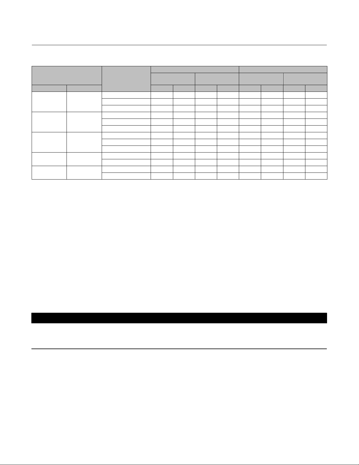
Table 2. Additional Shutoff Classification
Valve Valve Size, NPS Port Diameter, Inches Cage Style Leakage Class
ED
(CL150‐600)
2‐1/2 2.875
3 3.4375
3 2.875
4 2.875
4 4.375 Equal Percentage, Linear, Whisper I, Cavitrol III, 1 stage
6
8
5.375 Whisper III (A3, B3, D3, D3), Cavitrol III, 2 stage
7 Equal Percentage, Linear, Whisper I, Cavitrol III, 1 stage
7 Cavitrol III, 2 stage
8 Equal Percentage, Linear, Whisper I, Cavitrol III, 1 stage
Equal Percentage, Linear, Whisper I, Cavitrolt III, 1 stage
Cavitrol III, 2 stage
V (for port
diameters from
2.875
through 8‐inch with
optional C‐seal trim)
WARNING
Personal injury could result from packing leakage. Valve packing was tightened before shipment; however, the packing
might require some readjustment to meet specific service conditions. Check with your process or safety engineer for any
additional measures that must be taken to protect against process media.
Valves with ENVIRO‐SEAL live‐loaded packing or HIGH‐SEAL live‐loaded packing will not require this initial
re‐adjustment. See the Fisher instruction manuals, ENVIRO‐SEAL Packing System for Sliding‐Stem Valves or HIGH‐SEAL
Live‐Loaded Packing System (as appropriate), for packing instructions. If you wish to convert your present packing
arrangement to ENVIRO‐SEAL packing, refer to the retrofit kits listed in the Parts Kit sub‐section near the end of this
manual.
Maintenance
Valve parts are subject to normal wear and must be inspected and replaced as necessary. Inspection and maintenance
frequency depends on the severity of service conditions. This section includes instructions for packing lubrication,
packing maintenance, trim maintenance, and ENVIRO‐SEAL bellows seal bonnet replacement. All maintenance
operations may be performed with the valve in the line.
WARNING
Avoid personal injury or property damage from sudden release of process pressure or bursting of parts. Before performing
any maintenance operations:
D Do not remove the actuator from the valve while the valve is still pressurized.
D Always wear protective gloves, clothing, and eyewear when performing any maintenance operations to avoid personal
injury.
D Disconnect any operating lines providing air pressure, electric power, or a control signal to the actuator. Be sure the
actuator cannot suddenly open or close the valve.
4
Page 5

Instruction Manual
D100390X012
D Use bypass valves or completely shut off the process to isolate the valve from process pressure. Relieve process pressure
from both sides of the valve. Drain the process media from both sides of the valve.
D Vent the pneumatic actuator loading pressure and relieve any actuator spring precompression.
D Use lock‐out procedures to be sure that the above measures stay in effect while you work on the equipment.
D The valve packing box may contain process fluids that are pressurized, even when the valve has been removed from the
pipeline. Process fluids may spray out under pressure when removing the packing hardware or packing rings, or when
loosening the packing box pipe plug.
D Check with your process or safety engineer for any additional measures that must be taken to protect against process
media.
Note
Whenever a gasket seal is disturbed by removing or shifting gasketed parts, install a new gasket during reassembly. This ensures a
good gasket seal because the used gasket may not seal properly.
ED Valve
February 2020
Packing Lubrication
Note
ENVIRO‐SEAL or HIGH‐SEAL packing does not require lubrication.
WARNING
To avoid personal injury or property damage resulting from fire or explosion, do not lubricate packing used in oxygen
service or in processes with temperatures over 260_C (500_F).
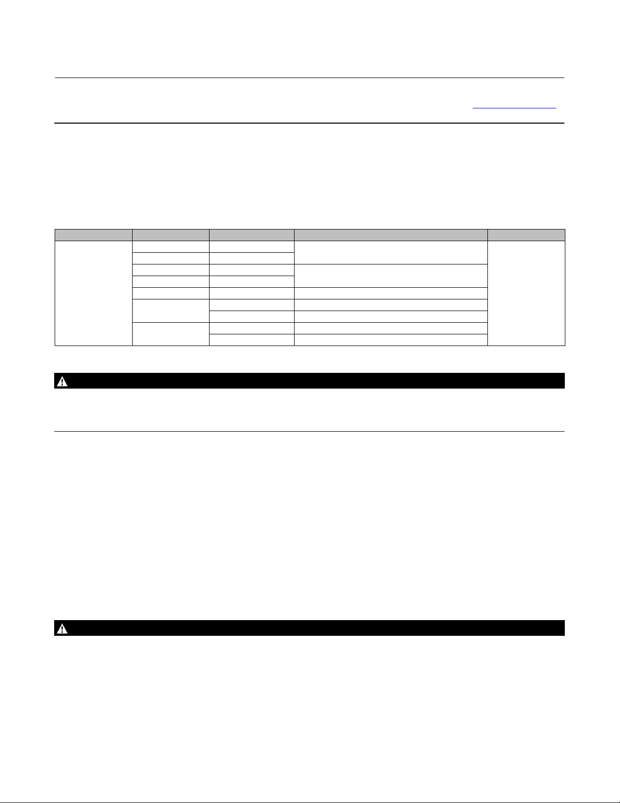
If a lubricator or lubricator/isolating valve (figure 2) is provided for PTFE/composition or other packings that require
lubrication, it will be installed in place of the pipe plug (key 14, figure 18). Use a good quality silicon‐based lubricant.
Do not lubricate packing used in oxygen service or in processes with temperatures over 260_C (500_F). To operate the
lubricator, simply turn the cap screw clockwise to force the lubricant into the packing box. The lubricator/isolating
valve operates the same way except open the isolating valve before turning the cap screw and then close the isolating
valve after lubrication is completed.
Packing Maintenance
Note
For valves with ENVIRO‐SEAL packing, see the Fisher instruction manual, ENVIRO‐SEAL Packing System for Sliding‐Stem Valves,
D101642X012
For valves with HIGH‐SEAL packing, see the Fisher instruction manual, HIGH‐SEAL Live‐Loaded Packing System, D101453X012
packing instructions.
, for packing instructions.
, for
Key numbers refer to figure 3 for PTFE V‐ring packing and to figure 4 for PTFE/composition packing, unless otherwise
indicated.
5
Page 6
ED Valve
February 2020
Figure 2. Lubricator and Lubricator/Isolating Valve (optional)
LUBRICATOR
10A9421‐A
AJ5428‐D
A0832‐2
LUBRICATOR/ISOLATING VALVE
Instruction Manual
D100390X012
For spring‐loaded single PTFE V‐ring packing, the spring (key 8, figure 3) maintains a sealing force on the packing. If
leakage is noted around the packing follower (key 13, figure 3), check to be sure the shoulder on the packing follower
is touching the bonnet. If the shoulder is not touching the bonnet, tighten the packing flange nuts (key 5, figure 18)
until the shoulder is against the bonnet. If leakage cannot be stopped in this manner, proceed to the Replacing
Packing procedure.
If there is undesirable packing leakage with other than spring‐loaded packing, first try to limit the leakage and
establish a stem seal by tightening the packing flange nuts.
If the packing is relatively new and tight on the stem, and if tightening the packing flange nuts does not stop the
leakage, the valve stem may be worn or nicked so that a seal cannot be made. The surface finish of a new valve stem is
critical for making a good packing seal. If the leakage comes from the outside diameter of the packing, the leakage
may be caused by nicks or scratches around the packing box wall. If performing any of the following procedures,
inspect the valve stem and packing box wall for nicks and scratches.
Replacing Packing
WARNING
Refer to the WARNING at the beginning of the Maintenance section in this instruction manual.
1. Isolate the control valve from the line pressure, release pressure from both sides of the valve body, and drain the
process media from both sides of the valve. If using a power actuator, also shut off all pressure lines to the power
actuator, and release all pressure from the actuator. Use lock‐out procedures to be sure that the above measures
stay in effect while you work on the equipment.
2. Disconnect the operating lines from the actuator and any leak‐off piping from the bonnet. Disconnect the stem
connector, then remove the actuator from the valve by unscrewing the yoke locknut (key 15, figure 18) or the hex
nuts (key 26, figure 18).
6
Page 7
Instruction Manual
(1
3)
(2)
D100390X012
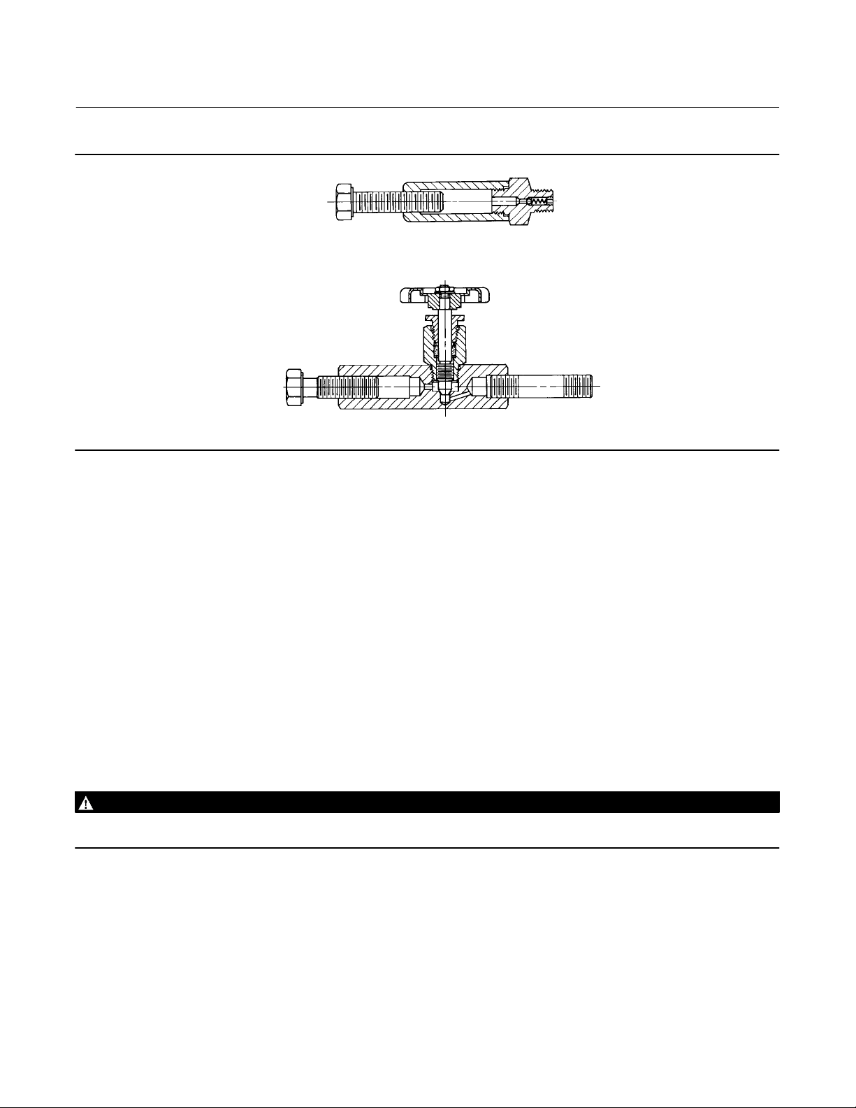
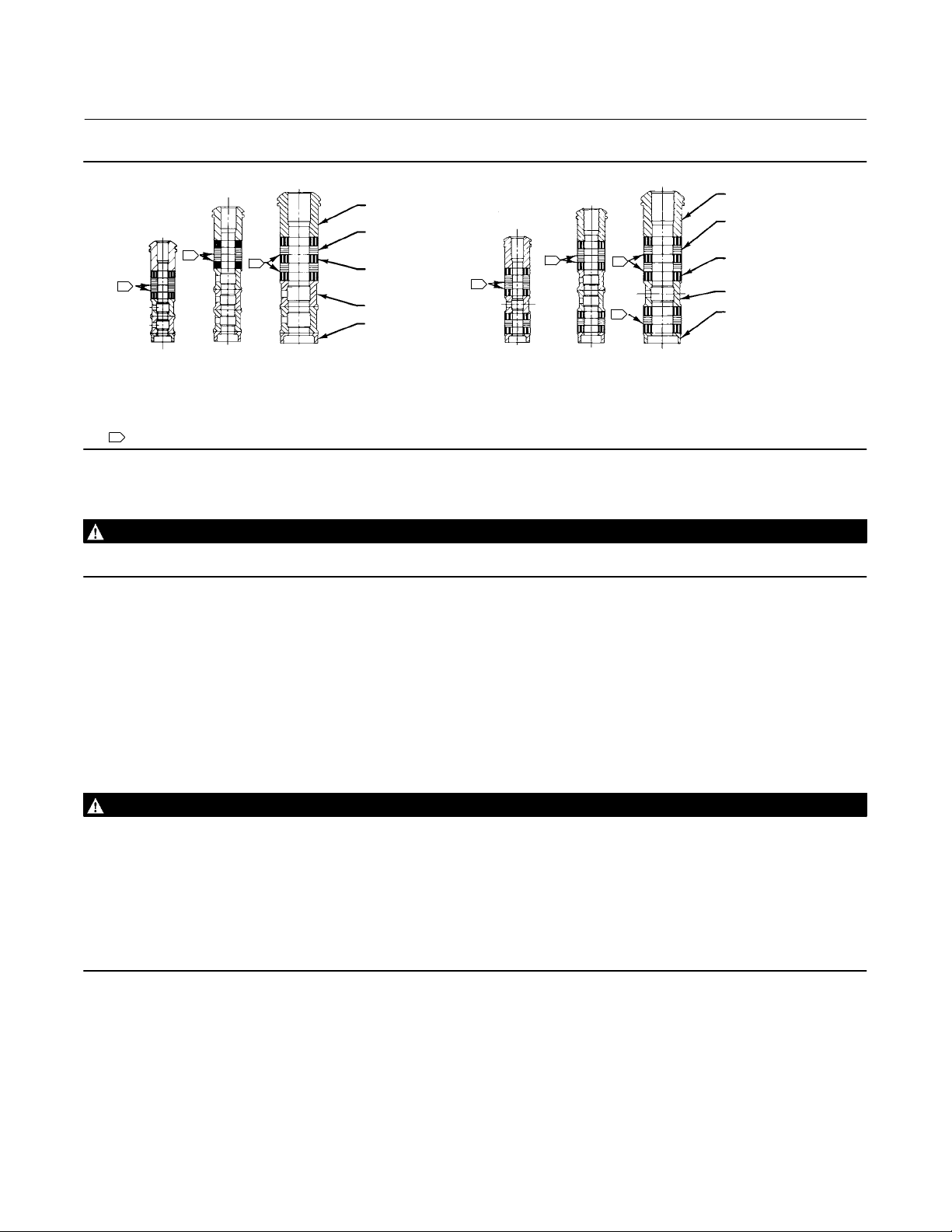
Figure 3. PTFE V‐Ring Packing Arrangements for Plain or Extension Bonnets
UPPER WIPER
(KEY 12)
PACKING
FOLLOWER
(KEY 13)
WASHER
(KEY 10)
SPRING
(KEY 8)
PACKING BOX
RING (KEY 11)
FOR 316 OR 17‐4PH SST
METAL PACKING BOX PARTS
12A7837‐A
12A8187-C 12A7814-C 12A7839-A
ASSEMBLY 1
(POSITIVE
PRESSURES)
ASSEMBLY 2
(VACUUM)
ASSEMBLY 3
(POSITIVE
PRESSURES
& VACUUM)
ASSEMBLY 1
(POSITIVE
PRESSURES)
9.5 mm (3/8 INCH) STEM 12.7 mm (1/2 INCH) STEM 19.1, 25.4, OR 31.8 mm
NOTES:
1
AND LOWER WIPER ARE PART OF PACKING SET (KEY 6).
2 REQ'D FOR DOUBLE ARRANGEMENTS, EXCEPT LOWER WIPER.
C0783
MALE ADAPTOR, PACKING RING, FEMALE ADAPTOR,
FEMALE
ADAPTOR
PACKING RING
MALE
ADAPTOR
LOWER WIPER
1
1
1
SINGLE ARRANGEMENTS
ASSEMBLY 2
(VACUUM)
ASSEMBLY 3
(POSITIVE
PRESSURES
& VACUUM)
DOUBLE ARRANGEMENTS
1
FEMALE
1
ADAPTOR
PACKING RING
1
MALE
ADAPTOR
1
LOWER
WIPER
1
FOR ALL OTHER METAL PACKING
ASSEMBLY 1
(POSITIVE
PRESSURES)
ASSEMBLY 2
(VACUUM)
(3/4, 1, OR 1‐1/4 INCH) STEM
BOX PART MATERIALS
ASSEMBLY 3
(POSITIVE
PRESSURES
& VACUUM)
UPPER WIPER
(KEY 12)
PACKING
FOLLOWER
(KEY 13)
SPACER (KEY 8)
PACKING BOX
RING (KEY 11)
UPPER WIPER
(KEY 12)
PACKING
FOLLOWER (KEY 13)
MALE
ADAPTOR
PACKING RING (KEY 7)
FEMALE
ADAPTOR
LANTERN
RING
(KEY 8)
1
PACKING BOX
RING (KEY 11)
LOWER
WIPER
ED Valve
February 2020
1
1
1
1
Table 3. Body‐to‐Bonnet Bolt Torque Guidelines
Valve Size, NPS Bolt Torques
ED EAD
NSm LbfSft NSm LbfSft
SA193‐B7 SA193‐B8M
1‐1/4 or less 1 129 95 64 47
1‐1/2, 1‐1/2 x 1, 2, or 2 x 1 2 or 2 x 1 96 71 45 33
2‐1/2 or 2‐1/2 x 1‐1/2 3 or 3 x 1‐1/2 129 95 64 47
3, 3 x 2, or 3 x 2‐1/2 4 or 4 x 2 169 125 88 65
4, 4 x 2‐1/2, or 4 x 3 6 or 6 x 2‐1/2 271 200 156 115
6 ‐ ‐ ‐ 549 405 366 270
8 ‐ ‐ ‐ 746 550 529 390
1. Determined from laboratory tests.
2. SA193‐B8M annealed.
3. For other materials, contact your Emerson sales office
for torque values.
,
7
Page 8

ED Valve
February 2020
Instruction Manual
D100390X012
3. Loosen the packing flange nuts (key 5, figure 18) so that the packing is not tight on the valve stem. Remove any
travel indicator parts and stem locknuts from the valve stem threads.
WARNING
To avoid personal injury or property damage caused by uncontrolled movement of the bonnet, loosen the bonnet by
following the instructions in the next step. Do not remove a stuck bonnet by pulling on it with equipment that can stretch
or store energy in any other manner. The sudden release of stored energy can cause uncontrolled movement of the bonnet.
Note
The following step also provides additional assurance that the valve body fluid pressure has been relieved.
CAUTION
Avoid damaging the seating surface caused by the valve plug and stem assembly dropping from the bonnet (key 1, figure
18) after being lifted part way out. When lifting the bonnet, temporarily install a valve stem locknut on the valve stem. This
locknut will prevent the valve plug and stem assembly from dropping out of the bonnet.
If the cage starts to lift with the bonnet, tap it with a plastic mallet, or other soft material, to be sure it stays in the valve.
4. Hex nuts (key 16, figure 19, 20, or 21) or cap screws (not shown) attach the bonnet (key 1, figure 18) to the valve
body (key 1, figure 19, 20, or 21). Loosen these nuts or cap screws approximately 3 mm (1/8 inch). Then loosen the
body‐to‐bonnet gasketed joint by either rocking the bonnet or prying between the bonnet and valve. Work the
prying tool around the bonnet until the bonnet loosens. If no fluid leaks from the joint, remove the nuts or cap
screws completely and carefully lift the bonnet off the valve.
5. Remove the locknut and separate the valve plug and stem from the bonnet. Set the parts on a protective surface to
prevent damage to gasket or seating surfaces.
6. Remove the bonnet gasket (key 10, figure 19, 20, or 21) and cover the opening in the valve to protect the gasket
surface and prevent foreign material from getting into the valve body cavity.
7. Remove the packing flange nuts, packing flange, upper wiper, and packing follower (keys 5, 3, 12, and 13, figure
18). Carefully push out all the remaining packing parts from the valve side of the bonnet using a rounded rod or
other tool that will not scratch the packing box wall. Clean the packing box and the metal packing parts.
8. Inspect the valve stem threads and packing box surfaces for any sharp edges which might cut the packing.
Scratches or burrs could cause packing box leakage or damage to the new packing. If the surface condition cannot
be improved by light sanding, replace the damaged parts by following the appropriate steps in the Trim
Maintenance procedure.
9. Remove the cover protecting the valve body cavity and install a new bonnet gasket (key 10, figure 19 through 21),
making sure the gasket seating surfaces are clean and smooth. Place the valve plug and stem into the valve body,
making sure it is properly centered on the seat ring. Then slide the bonnet over the stem and onto the stud bolts
(key 16, figure 19, 20, or 21) or onto the valve body cavity if cap screws (not shown) will be used instead.
8
Page 9
Instruction Manual
D100390X012
ED Valve
February 2020
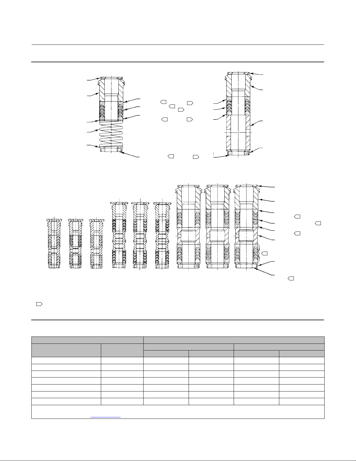
Figure 4. PTFE/Composition Packing Arrangements for Plain or Extension Bonnets
UPPER WIPER
(KEY 12)
PACKING
FOLLOWER (KEY 13)
PACKING RING (KEY 7)
LANTERN RING
(KEY 8)
PACKING BOX
RING (KEY 11)
9.5 mm
(3/8‐INCH)
12A8088‐A
12A7815‐A
12A8173‐A
A5904
STEM
Note
Proper performance of the bolting procedures in step 10 compresses the spiral wound gasket (key 12, figure 19 or 20) or load ring
(key 26, figure 21) enough to both load and seal the seat ring gasket (key 13, figure 19, 20, or 21). It also compresses the outer
edge of the bonnet gasket (key 10, figure 19 through 21) enough to seal the body‐to‐bonnet joint.
12.7 mm
(1/2‐INCH)
STEM
19.1, 25.4, & 31.8 mm
(3/4, 1 & 1‐1/4 INCH)
STEM
TYPICAL (DOUBLE) ARRANGEMENT
The bolting procedures in step 10 include‐‐but are not limited to‐‐ensuring that bolting threads are clean, and evenly tightening
the cap screws, or the nuts onto the studs, in a crisscross pattern. Tightening one cap screw or nut may loosen an adjacent cap
screw or nut. Repeat the crisscross tightening pattern several times until each cap screw or nut is tight and the body‐to‐bonnet
seal is made.
10. Install bolting, using accepted bolting procedures during tightening, so that the body‐to‐bonnet joint will
withstand test pressures and application service conditions. Use the bolt torques in table 3 as guidelines.
11. Install new packing and the metal packing box parts according to the appropriate arrangement in figure 3, 4, or 5.
Place a smooth‐edged pipe over the valve stem and gently tap each soft packing part into the packing box.
12. Slide the packing follower, upper wiper, and packing flange (keys 13, 12, and 3, figure 18) into position. Lubricate
the packing flange studs (key 4, figure 18) and the faces of the packing flange nuts (key 5, figure 18). Install the
packing flange nuts.
13. For spring‐loaded PTFE V‐ring packing, tighten the packing flange nuts until the shoulder on the packing follower
(key 13, figure 18) contacts the bonnet.
For graphite packing, tighten the packing flange nuts to the maximum recommended torque shown in table 4.
Then, loosen the packing flange nuts, and retighten them to the recommended minimum torque shown in table 4.
For other packing types, tighten the packing flange nuts alternately in small equal increments until one of the nuts
reaches the minimum recommended torque shown in table 4. Then, tighten the remaining flange nut until the
packing flange is level and at a 90‐degree angle to the valve stem.
For ENVIRO‐SEAL or HIGH‐SEAL live‐loaded packing, refer to the note at the beginning of Packing Maintenance.
14. Mount the actuator on the valve assembly and reconnect the actuator and valve stem according to the procedure
in the appropriate actuator instruction manual.
9
Page 10
ED Valve
February 2020
Instruction Manual
D100390X012
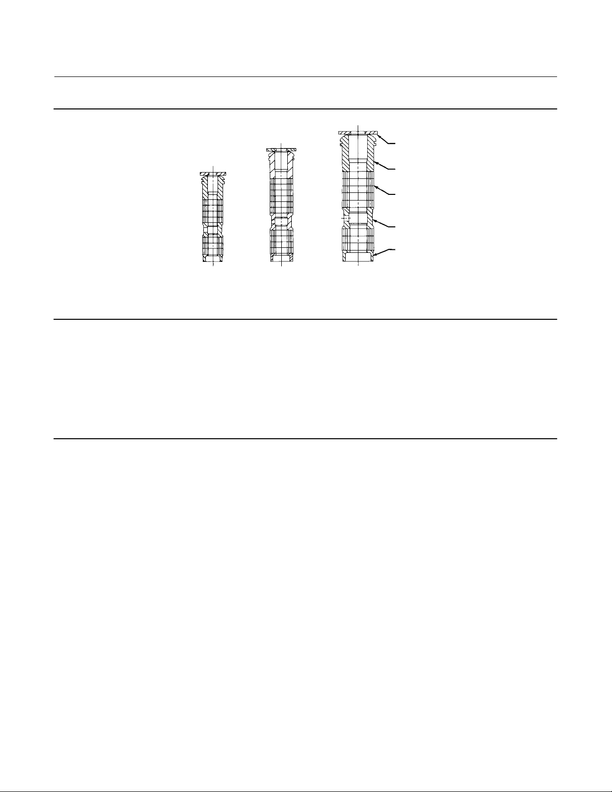
Figure 5. Graphite Ribbon/Filament Packing for Plain or Extension Bonnets
PACKING
FOLLOWER (KEY 13)
GRAPHITE RIBBON
1
1
14A3411‐C 13A9775‐E 13A9776‐D
9.5 mm
B2350
(3/8‐INCH)
NOTES:
1
STEM
(1/2‐INCH)
0.102 mm (0.004 INCH) THICK SACRIFICIAL ZINC WASHERS; USE ONLY ONE BELOW EACH GRAPHITE RIBBON RING.
1
12.7 mm
STEM
19.1, 25.4, OR 31.8 mm
(3/4, 1, OR 1‐1/4 INCH)
STEM
SINGLE ARRANGEMENTS DOUBLE ARRANGEMENTS
PACKING RING (KEY 7)
GRAPHITE FILAMENT
PACKING RING
(KEY 7)
LANTERN RING (KEY 8)
PACKING BOX
RING (KEY 11)
1
1
14A2153‐D 14A1849‐E 14A1780‐D
9.5 mm
(3/8‐INCH)
STEM
Trim Maintenance
WARNING
Observe the warning at the start of the Maintenance section.
12.7 mm
(1/2‐INCH)
STEM
1
1
19.1, 25.4, OR 31.8 mm
(3/4, 1, OR 1‐1/4 INCH)
STEM
PACKING
FOLLOWER (KEY 13)
GRAPHITE RIBBON
PACKING RING (KEY 7)
GRAPHITE FILAMENT
PACKING RING (KEY 7)
LANTERN RING (KEY 8)
PACKING BOX
RING (KEY 11)
For C‐seal construction, see the appropriate C‐seal sections in this instruction manual.
Except where indicated, key numbers in this section are referenced in figure 19 for standard NPS 1 through 6
constructions, figure 20 for Whisper Trim III cage detail, figure 21 for the NPS 8 ED valve, and figures 22 and 23 for
WhisperFlo trim. Some valve plug constructions require three piston rings (key 6).
Disassembly
1. Remove the actuator and the bonnet according to steps 1 through 5 of the Replacing Packing procedure in the
Maintenance section.
WARNING
Avoid personal injury or property damage from valve or packing leakage.
The graphite piston rings in an ED or EAD valve are brittle and in two pieces. Use care to avoid damage to the piston rings
caused by dropping or rough handling.
Any damage to the gasket sealing surfaces could cause the valve to leak. The surface finish of the valve stem (key 7) is
critical for making a good packing seal. The inside surface of the cage or cage/baffle assembly (key 3), or cage retainer (key
31), is critical for smooth operation of the valve plug and for making a seal with the piston rings (key 6). The seating
surfaces of the valve plug (key 2) and seat ring (key 9) are critical for proper shutoff. Protect these parts accordingly while
disassembling the trim.
2. Remove the packing flange nuts, packing flange, upper wiper, and packing follower (keys 5, 3, 12, and 13, figure
18). Carefully push out all the remaining packing parts from the valve side of the bonnet using a rounded rod or
other tool that will not scratch the packing box wall. Clean the packing box and the metal packing parts.
3. Inspect the valve stem threads and packing box surfaces for any sharp edges which might cut the packing.
Scratches or burrs could cause packing box leakage or damage to the new packing. If the surface condition cannot
be improved by light sanding, replace the damaged parts.
10
Page 11
Instruction Manual
D100390X012
ED Valve
February 2020
Table 4. Recommended Torque for Packing Flange Nuts
GRAPHITE TYPE PACKING PTFE TYPE PACKING
VALVE STEM DIAMETER
mm Inches NSm LbfSin NSm LbfSin NSm LbfSin NSm LbfSin
9.5 3/8
12.7 1/2
19.1 3/4
25.4 1
31.8 1‐1/4
PRESSURE RATING
CL125, 150 3 27 5 40 1 13 2 19
CL250, 300 4 36 6 53 2 17 3 26
CL600 6 49 8 73 3 23 4 35
CL125, 150 5 44 8 66 2 21 4 31
CL250, 300 7 59 10 88 3 28 5 42
CL600 9 81 14 122 4 39 7 58
CL125, 150 11 99 17 149 5 47 8 70
CL250, 300 15 133 23 199 7 64 11 95
CL600 21 182 31 274 10 87 15 131
CL300 26 226 38 339 12 108 18 162
CL600 35 310 53 466 17 149 25 223
CL300 36 318 54 477 17 152 26 228
CL600 49 437 74 655 24 209 36 314
Minimum
Torque
Maximum
Torque
Minimum
Torque
Maximum
Torque
4. Remove the load ring (key 26) from an NPS 8 ED valve, or the cage adaptor (key 4) from any restricted‐trim valve
through NPS 4, and wrap it for protection.
5. On an NPS 6 ED valve with a Whisper Trim III cage or WhisperFlo trim, remove the bonnet spacer (key 32) and
bonnet gasket (key 10) on top of the spacer. Then on any construction with a cage retainer (key 31), remove the
cage retainer and its associated gaskets. A Whisper Trim III and WhisperFlo cage retainer has two 3/8 inch‐16 UNC
tappings in which screws or bolts can be installed for lifting.
6. Remove the cage or cage/baffle assembly (key 3) and the associated gaskets (keys 10, 11, and 12), and shim (key
51 for the ED valve, key 27 for the EAD valve). If the cage is stuck in the valve, use a rubber mallet to strike the
exposed portion of the cage at several points around its circumference.
7. Remove the seat ring or liner (key 9), seat ring gasket (key 13), and the seat ring adaptor (key 5) and adaptor gasket
(key 14) where used in a restricted‐trim seat ring construction.
8. Inspect parts for wear or damage which would prevent proper operation of the valve. Replace or repair trim parts
according to the following procedure for Lapping Metal Seats or other valve plug maintenance procedures as
appropriate.
Lapping Metal Seats
CAUTION
To avoid damaging the ENVIRO‐SEAL bellows seal bonnet assembly, do not attempt to lap the metal seating surfaces. The
design of the assembly prevents rotation of the stem and any forced lapping rotation will damage internal components of
the ENVIRO‐SEAL Bellows Seal bonnet.
With metal‐seat constructions, seating surfaces of the valve plug and seat ring or liner (keys 2 and 9, figure 19, 20, or
21) can be lapped for improved shutoff. (Deep nicks should be machined out rather than ground out.) Use a good
quality lapping compound of a mixture of 280 to 600‐grit. Apply compound to the bottom of the valve plug.
Assemble the valve to the extent that the cage and the cage retainer and bonnet spacer (if used) are in place and the
bonnet is bolted to the valve. A simple handle can be made from a piece of strap iron locked to the valve plug stem
with nuts. Rotate the handle alternately in each direction to lap the seats. After lapping, remove the bonnet and clean
the seat surfaces. Completely assemble as described in the Assembly portion of the Trim Maintenance procedure and
test the valve for shutoff. Repeat the lapping procedure if leakage is still excessive.
11
Page 12

ED Valve
February 2020
Instruction Manual
D100390X012
Valve Plug Maintenance
Except where indicated, key numbers in this section are referenced in figure 19 for standard NPS 1 through 6
constructions, figure 20 for Whisper Trim III detail, figure 21 for the NPS 8 ED valve, and figures 22 and 23 for
WhisperFlo trim. Some valve plug constructions require three piston rings (key 6).
CAUTION
To avoid the piston ring (key 6) not sealing properly, be careful not to scratch the surfaces of the ring groove in the valve
plug or any of the surfaces of the replacement ring.
1. With the valve plug (key 2) removed according to the Disassembly portion of the Trim Maintenance procedure,
proceed as appropriate:
For the carbon‐filled PTFE piston ring, The ring is split in one place. If there is visible damage, spread the ring slightly
and remove it from the groove in the valve plug.
To install a carbon‐filled PTFE piston ring, Spread the ring apart slightly at the split and install it over the stem and
into the groove in the valve plug. The open side must face along the stem, depending on flow directions, as shown
in view A of figure 19.
For the graphite piston ring, The ring can be easily removed since it is in two pieces. A new graphite piston ring is
furnished as a complete ring. Use a vise with smooth or taped jaws to break this replacement ring into halves. Place
the new ring in the vise so that the jaws will compress the ring into an oval. Slowly compress the ring until it snaps
on both sides. If one side snaps first, do not try to tear or cut the other side. Instead, keep compressing the ring until
the other side snaps. Be sure to match the broken ends when installing the ring in the valve plug groove.
CAUTION
Never reuse an old stem or adaptor with a new valve plug. Using an old stem or adaptor with a new plug requires drilling a
new pin hole in the stem (or adaptor in case an ENVIRO‐SEAL bellows seal bonnet is being used). This drilling weakens the
stem or adaptor and may cause failure in service. However, a used valve plug may be reused with a new stem or adaptor.
Note
For plain bonnets and style 1 extension bonnets, the valve plug (key 2), valve stem (key 7), and pin (key 8) are available completely
assembled. Refer to the Key 2, 7, and 8 Valve Plug and Stem Assembly tables in the Parts List.
2. To replace the valve stem (key 7), drive out the pin (key 8). Unscrew the valve plug from the stem or adaptor.
3. To replace the adaptor (key 24, figure 18) on ENVIRO‐SEAL bellows seal bonnets, place the plug stem assembly and
valve plug in a soft‐jaw chuck or other type of vise so that the jaws grip a portion of the valve plug that is not a
seating surface. Drive out the pin (key 36, figure 18). Reverse the plug stem assembly and valve plug in the soft‐jaw
chuck or vise. Grip the flat areas on the valve stem just below the threads for the actuator/stem connection.
Unscrew the valve plug/adaptor assembly (key 24, figure 18) from the valve stem assembly (key 20, figure 18).
4. Screw the new stem or adaptor into the valve plug. Tighten to the torque value given in table 5. Refer to table 5 to
select the proper drill size. Drill through the stem or adaptor, using the hole in the valve plug as a guide. Remove
any chips or burrs and drive in a new pin to lock the assembly.
5. For ENVIRO‐SEAL bellows seal bonnets, grip the flats of the stem extending out of the top of the bellows shroud
with a soft‐jaw chuck or other type of vise. Screw the valve plug/adaptor assembly onto the valve stem. Tighten as
12
Page 13

Instruction Manual
D100390X012
ED Valve
February 2020
necessary to align the pin hole in the stem with one of the holes in the adaptor. Secure the adaptor to the stem with
a new pin.
Assembly
Except where indicated, key numbers are referenced in figure 19 for standard NPS 1 through 6 constructions, figure 20
for Whisper Trim III detail, figure 21 for the NPS 8 ED valve, and figures 22 and 23 for WhisperFlo trim.
Table 5. Valve Stem Connection Torque and Pin Replacement
VALVE STEM CONNECTION (VSC)
mm Inch NSm LbfSft
9.5
12.7
19.1
25.4
31.8
3/8
1/2
3/4
1
1‐1/4
40 to 47
81 to 115
237 to 339
420 to 481
827 to 908
1. With a restricted‐trim seat ring construction, install the adaptor gasket (key 14) and seat ring adaptor (key 5).
2. Install the seat ring gasket (key 13), seat ring or liner (key 9).
3. Install the cage or cage/baffle assembly (key 3). Any rotational orientation of the cage or assembly with respect to
the valve is acceptable. A Whisper Trim III cage designated by level A3, B3, or C3 may be installed with either end
up. The level D3 cage/baffle assembly, however, must be installed with the hole pattern end next to the seat ring. If
a cage retainer (key 31) is to be used, place it on top of the cage.
4. Slide the valve plug (key 2) and stem assembly, or valve plug and ENVIRO‐SEAL bellows seal assembly, into the cage
until the piston ring(s) is level with the top of the cage (key 3) or cage retainer (key 31).
5. Installing piston rings (key 6):
TORQUE,
MINIMUM TO MAXIMUM
175 to 250
310 to 355
610 to 670
25 to 35
60 to 85
DRILL SIZE, INCH
3/32
1/8
3/16
1/4
1/4
a. For valve plugs with a single piston ring: Make sure the piston ring is evenly engaged into the entrance chamfer
at the top of the cage or cage retainer ring. Carefully press the piston ring into the cage or cage retainer ring.
b. For valve plugs with multiple piston rings: As each piston ring is slid into the cage, make sure the ring is evenly
engaged in the entrance chamfer at the top of the cage or cage retainer. Also, make sure to offset the fracture in
the rings to minimize leakage. Carefully press each piston ring into the cage or cage retainer ring.
6. Place the gaskets (keys 12, 11 or 14 if used, and 10) and the shim (key 27 or 51) if used, on top of the cage or cage
retainer. If there is a cage adaptor (key 4) or a bonnet spacer (key 32), set it on the cage or cage retainer gaskets and
place another flat sheet gasket (key 10) on top of the adaptor or spacer. If there is only a cage retainer, place
another flat sheet gasket on the retainer.
7. With an NPS 8 ED valve, install the load ring (key 26).
8. Mount the bonnet on the valve and complete assembly according to steps 10 through 14 of the Replacing Packing
procedure. Be sure to observe the note prior to step 10.
Retrofit: Installing C‐seal Trim
Note
Additional actuator thrust is required for a valve with C‐seal trim. When installing C‐seal trim in an existing valve, contact your
Emerson sales office
Assemble the new valve plug/retainer assembly (with C‐seal plug seal) using the following instructions:
for assistance in determining new actuator thrust requirements.
13
Page 14

ED Valve
February 2020
Instruction Manual
D100390X012
CAUTION
To avoid leakage when the valve is returned to service, use appropriate methods and materials to protect all sealing
surfaces of the new trim parts while assembling the individual parts and during installation in the valve body.
1. Apply a suitable high‐temperature lubricant to the inside diameter of the C‐seal plug seal. Also, lubricate the
outside diameter of the valve plug where the C‐seal plug seal must be pressed into the proper sealing position
(figure 6).
2. Orient the C‐seal plug seal for correct sealing action based on the process fluid flow direction through the valve.
D The open interior of the C‐seal plug seal must face up in a valve with flow‐up construction (figure 6).
D The open interior of the C‐seal plug seal must face down in a valve with flow‐down construction (figure 6).
Figure 6. Fisher ED with C‐seal Trim
FLOW DOWN
VIEW A
FLOW UP
3
6
6
37B1045‐A
Note
An installation tool must be used to properly position the C‐seal plug seal on the valve plug. A tool is available as a Fisher spare part
or a tool could be manufactured following the dimensions given in figure 7.
3. Place the C‐seal plug seal over the top of the valve plug and press the C‐seal plug seal onto the plug using the C‐seal
installation tool. Carefully press the C‐seal plug seal onto the plug until the installation tool contacts the horizontal
reference surface of the valve plug (figure 8).
4. Apply a suitable high‐temperature lubricant to the threads on the plug. Then, place the C‐seal retainer onto the
plug and tighten the retainer using an appropriate tool such as a strap wrench.
37B1397‐A
CAVITROL III 2‐STAGE
14
Page 15

Instruction Manual
D100390X012
ED Valve
February 2020
5. Using an appropriate tool such as a center punch, stake the threads on top of the plug in one place (figure 9) to
secure the C‐seal retainer.
6. Install the new plug/retainer assembly with C‐seal plug seal on the new stem following the appropriate instructions
in the Trim Replacement section of this manual.
7. Install piston rings by following instructions in the Trim Replacement section of this manual.
8. Remove the existing valve actuator and bonnet following the appropriate instructions in the Replacing Packing
section of this manual.
CAUTION
Do not remove the existing valve stem from the valve plug unless you are planning to replace the valve stem.
Never reuse an old valve stem with a new plug or reinstall a valve stem after it has been removed. Replacing a valve stem
requires drilling a new pin hole in the stem. This drilling weakens the stem and may cause failure in service. However, a
used valve plug may be reused with a new valve stem.
9. Remove the existing valve stem and plug, cage, and seat ring from the valve body following the appropriate
instructions in the Trim Removal section of this manual.
10. Replace all gaskets according to appropriate instructions in the Trim Replacement section of this manual.
11. Install the new seat ring, cage, valve plug/retainer assembly, and stem into the valve body and completely
reassemble the valve package following the appropriate instructions in the Trim Replacement section of this
manual.
CAUTION
To avoid excessive leakage and seat erosion, the valve plug must be initially seated with sufficient force to overcome the
resistance of the C‐seal plug seal and contact the seat ring. You can correctly seat the valve plug by applying the full
actuator load. This force will adequately drive the valve plug to the seat ring, thus giving the C‐seal plug seal a
predetermined permanent set. Once this is done, the plug/retainer assembly, the cage, and the seat ring become a
matched set.
With full actuator force applied and the valve plug fully seated, align the actuator travel indicator scale with the lower
end of valve travel. Refer to the appropriate actuator instruction manual for information on this procedure.
Replacement of Installed C‐seal Trim
Trim Removal (C‐seal Constructions)
1. Remove the valve actuator and bonnet following the appropriate instructions in the Replacing Packing section of
this manual.
CAUTION
To avoid leakage when the valve is returned to service, use appropriate methods and materials to protect all sealing
surfaces of the trim parts during maintenance.
Use caution when removing piston ring(s) and C‐seal plug seal to avoid scratching any sealing surface.
15
Page 16

ED Valve
February 2020
Instruction Manual
D100390X012
FOR VALVE
PLUGS
FITTING
PORT SIZE
(Inches)
2.875 82.55
3.4375 101.6
3.625 104.394
4.375 125.984
5.375 142.748
7 184.15
8 209.55
A B C D E F G H
52.324 ‐
52.578
58.674 ‐
58.928
65.024 ‐
65.278
83.439 ‐
83.693
100.076 ‐
100.33
141.376 ‐
141.630
166.776 ‐
167.030
4.978 ‐ 5.029 3.708 ‐ 3.759 41.148
4.978 ‐ 5.029 3.708 ‐ 3.759 50.8
4.978 ‐ 5.029 3.708 ‐ 3.759 50.8
4.978 ‐ 5.029 3.708 ‐ 3.759 50.8
4.978 ‐ 5.029 3.708 ‐ 3.759 45.974
4.978 ‐ 5.029 3.708 ‐ 3.759 60.198
4.978 ‐ 5.029 3.708 ‐ 3.759 55.88
FOR VALVE
PLUGS
FITTING
PORT SIZE
(Inches)
2.875 3.25 2.060 ‐ 2.070 0.196 ‐ 0.198 0.146 ‐ 0.148 1.62 2.074 ‐ 2.078 2.170 ‐ 2.190 2.791 ‐ 2.797 24B9816X012
3.4375 4.00 2.310 ‐ 2.320 0.196 ‐ 0.198 0.146 ‐ 0.148 2.00 2.402 ‐ 2.406 2.498 ‐ 2.518 3.353 ‐ 3.359 24B5612X012
3.625 4.11 2.560 ‐ 2.570 0.196 ‐ 0.198 0.146 ‐ 0.148 2.00 2.714 ‐ 2.718 2.810 ‐ 2.830 3.541 ‐ 3.547 24B3630X012
4.375 4.96 3.285 ‐ 3.295 0.196 ‐ 0.198 0.146 ‐ 0.148 2.00 3.439 ‐ 3.443 3.535 ‐ 3.555 4.291 ‐ 4.297 24B3635X012
5.375 5.62 3.940 ‐ 3.950 0.196 ‐ 0.198 0.146 ‐ 0.148 1.81 4.088 ‐ 4.092 4.184 ‐ 4.204 5.048 ‐ 5.054 23B9193X012
7 7.25 5.566 ‐ 5.576 0.196 ‐ 0.198 0.146 ‐ 0.148 2.37 5.714 ‐ 5.718 5.810 ‐ 5.830 6.674 ‐ 6.680 23B9180X012
8 8.25 6.566 ‐ 6.576 0.196 ‐ 0.198 0.146 ‐ 0.148 2.20 6.714 ‐ 6.718 6.810 ‐ 6.830 7.674 ‐ 7.680 24B9856X012
A B C D E F G H
DIMENSIONS, mm
(See Drawing Below)
DIMENSIONS, INCHES
(See Drawing Below)
52.680 ‐
52.781
61.011 ‐
61.112
68.936 ‐
69.037
87.351 ‐
87.452
103.835 ‐
103.937
145.136 ‐
145.237
170.536 ‐
170.637
55.118 ‐
55.626
63.449 ‐
63.957
71.374 ‐
71.882
89.789 ‐
90.297
106.274 ‐
106.782
147.574 ‐
148.082
172.974 ‐
173.482
Part Number
(To Order
A Tool)
70.891 ‐ 71.044 24B9816X012
85.166 ‐ 85.319 24B5612X012
89.941 ‐ 90.094 24B3630X012
108.991 ‐ 109.144 24B3635X012
128.219 ‐ 128.372 23B9193X012
169.520 ‐ 169.672 23B9180X012
194.920 ‐ 195.072 24B9856X012
Part Number
(To Order
A Tool)
Figure 7. C‐seal Plug Seal Installation Tool
45° X 1.524 (0.06)
8° ‐ 9°
C
D
mm (inch)
A6777
∅A
∅B
∅F
∅G
∅H
E
45° X 0.508 (0.02)
BREAK SHARP
CORNER
45° X 0.254 (0.01)
MAX
16
Page 17

Instruction Manual
D100390X012
Figure 8. Installing the C‐seal Plug Seal Using the Installation Tool
INSTALLATION
TOOL
C‐seal
METAL
PLUG
SEAL
ED Valve
February 2020
VALVE
PLUG
NOTE:
PRESS INSTALLATION TOOL OVER VALVE PLUG
UNTIL THE TOOL CONTACTS THE HORIZONTAL
REFERENCE SURFACE OF THE VALVE PLUG.
A6778
Figure 9. Stake the Threads of the C‐seal Retainer
DEFORM THREAD TO
STAKE C‐seal RETAINER
PISTON
RING
RETAINER
C‐seal
METAL
PLUG
SEAL
A6779
HORIZONTAL
REFERENCE
SURFACE
FLOW DOWN
VALVE
PLUG
FLOW DOWN
CAUTION
Do not remove the valve stem from the plug/retainer assembly unless you are planning to replace the valve stem.
Never reuse an old valve stem with a new plug or reinstall a valve stem after it has been removed. Replacing a valve stem
requires drilling a new pin hole in the stem. This drilling weakens the stem and may cause failure in service. However, a
used valve plug may be reused with a new valve stem.
17
Page 18

ED Valve
Instruction Manual
February 2020
Figure 10. Lower (Valve Plug to Seat Ring) and Upper (C‐seal Plug Seal to Cage) Seating Surfaces
RETAINER
CAGE
PLUG
C‐seal METAL
PLUG SEAL
VALVE PLUG
1
CAGE
SEAT
RING
D100390X012
A6780
NOTE:
1
UPPER SEATING SURFACE IS THE AREA OF CONTACT BETWEEN THE C‐seal METAL PLUG SEAL AND THE CAGE.
UPPER SEATING SURFACE
Figure 11. Example of Machining the Lower (Valve Plug to Seat Ring)
and Upper (C‐seal Plug Seal to Cage) Seating Surfaces
C‐seal
RETAINER
PLUG
0.254 (0.010)
(4)
NOTE:
MUST EQUAL
A6781 / IL
REMOVAL OF 0.254 mm (0.010 inch) FROM THE VALVE PLUG
1
REMOVAL OF 0.254 mm (0.010 inch) FROM THE SEAT RING
PLUS
2
3
REMOVAL OF 0.508 mm (0.020 inch) FROM THE
UPPER SEATING SURFACE IN THE CAGE
4. THESE VALUES ARE FOR EXAMPLE ONLY. REMOVE ONLY THE
MINIMUM AMOUNT OF MATERIAL REQUIRED TO REFURBISH THE SEATS.
1
LOWER SEATING SURFACE
UPPER SEATING SURFACE
(4)
0.508 (0.020)
MACHINING OF THE UPPER
SEATING SURFACE MUST
EQUAL THE TOTAL MACHINING OF
THE LOWER SEATING SURFACE
(PLUG PLUS SEAT RING). IF NOT, THE
RETAINER MAY STRIKE THE UPPER
SEATING SURFACE BEFORE THE
VALVE PLUG PROPERLY SEATS ON
THE LOWER SEATING SURFACE.
CAGE
SEAT
RING
LOWER SEATING SURFACE
(4)
0.254 (0.010)
2
3
mm (inch)
2. Remove the plug/retainer assembly (with C‐seal plug seal), cage, and seat ring from the valve body following the
appropriate instructions in the Trim Removal section of this manual.
3. Locate the staked thread on top of the valve plug (figure 9). The staked thread secures the retainer. Use a drill with a
1/8 inch bit to drill out the staked area of the thread. Drill approximately 3 mm (1/8 inch) into the metal to remove
the staking.
4. Locate the break between sections of the piston ring(s). Using an appropriate tool such as a flat‐blade screwdriver,
carefully pry out the piston ring(s) from the groove(s) in the C‐seal retainer.
18
Page 19

Instruction Manual
D100390X012
ED Valve
February 2020
5. After removing the piston ring(s), locate the 1/4‐inch diameter hole in the groove. In a retainer with two piston ring
grooves, the hole will be found in the upper groove.
6. Select an appropriate tool such as a punch and place the tip of the tool into the hole with the body of the tool held
tangent to the outside diameter of the retainer. Strike the tool with a hammer to rotate the retainer and free it from
the valve plug. Remove the retainer from the plug.
7. Use an appropriate tool such as a flat‐blade screwdriver to pry the C‐seal plug seal off the plug. Use caution to avoid
scratches or other damage to the sealing surfaces where the C‐seal plug seal makes contact with the valve plug
(figure 10).
8. Inspect the lower seating surface where the valve plug contacts the seat ring for wear or damage which would
prevent proper operation of the valve. Also, inspect the upper seating surface inside the cage where the C‐seal plug
seal contacts the cage, and inspect the sealing surface where the C‐seal plug seal makes contact with the plug
(figure 10).
9. Replace or repair trim parts according to the following procedure for Lapping Metal Seats, Remachining Metal
Seats, or other valve plug maintenance procedures as appropriate.
Lapping Metal Seats (C‐seal Constructions)
Before installing a new C‐seal plug seal, lap the lower seating surface (valve plug to seat ring, figure 10) following
appropriate procedures in the Lapping Metal Seats section of this manual.
Remachining Metal Seats (C‐seal Constructions)
See figure 11. A valve plug with a C‐seal metal plug seal features two seating surfaces. One seating surface is found
where the valve plug contacts the seat ring. The second seating surface is found where the C‐seal plug seal contacts
the upper seating surface in the cage. If you machine the seats on the seat ring and/or plug, you must machine an
equal dimension from the seating area in the cage.
CAUTION
If metal is removed from the seat ring and plug and a corresponding amount is not removed from the cage seating area, the
C‐seal plug seal will be crushed as the valve closes and the C‐seal retainer will strike the seating area of the cage, preventing
the valve from closing.
Trim Replacement (C‐seal Constructions)
1. Apply a suitable high‐temperature lubricant to the inside diameter of the C‐seal plug seal. Also, lubricate the
outside diameter of the valve plug where the C‐seal plug seal must be pressed into the proper sealing position
(figure 6).
2. Orient the C‐seal plug seal for correct sealing action based on the process fluid flow direction through the valve.
D The open interior of the C‐seal plug seal must face up in a valve with flow‐up construction (figure 6).
D The open interior of the C‐seal plug seal must face down in a valve with flow‐down construction (figure 6).
Note
An installation tool must be used to properly position the C‐seal plug seal on the valve plug. A tool is available as a Fisher spare part
or a tool could be manufactured following the dimensions given in figure 7.
3. Place the C‐seal plug seal over the top of the valve plug and press it onto the plug using the installation tool.
Carefully press the C‐seal plug seal onto the plug until the installation tool contacts the horizontal reference surface
of the valve plug (figure 8).
19
Page 20

ED Valve
February 2020
Instruction Manual
D100390X012
4. Apply a suitable high‐temperature lubricant to the threads on the plug. Then, place the C‐seal retainer onto the
plug and tighten the retainer using an appropriate tool such as a strap wrench.
5. Using an appropriate tool such as a center punch, stake the threads on top of the plug in one place (figure 9) to
secure the C‐seal retainer.
6. Replace the piston ring(s) following instructions in the Trim Replacement section of this manual.
7. Return the seat ring, cage, plug/retainer assembly, and stem to the valve body and completely reassemble the valve
package following the appropriate instructions in the Trim Replacement section of this manual.
CAUTION
To avoid excessive leakage and seat erosion, the valve plug must be initially seated with sufficient force to overcome the
resistance of the C‐seal plug seal and contact the seat ring. You can correctly seat the valve plug by applying the full
actuator load. This force will adequately drive the valve plug to the seat ring, thus giving the C‐seal plug seal a
predetermined permanent set. Once this is done, the plug/retainer assembly, the cage, and the seat ring become a
matched set.
With full actuator force applied and the valve plug fully seated, align the actuator travel indicator scale with the lower
end of valve travel. Refer to the appropriate actuator instruction manual for information on this procedure.
ENVIRO‐SEAL Bellows Seal Bonnet
Replacing a Plain or Extension Bonnet with an ENVIRO‐SEAL Bellows Seal Bonnet
(Stem/Bellows Assembly)
1. Remove the actuator and bonnet according to steps 1 through 5 of the Replacing Packing procedure in the
Maintenance section.
2. Lift out the cage.
3. Remove and discard the existing bonnet gasket. Cover the valve body opening to protect sealing surfaces and to
prevent foreign material from entering the valve body cavity.
Note
The ENVIRO‐SEAL stem/bellows assembly for easy‐e valves is available only with a threaded and drilled plug/adaptor/stem
connection. The existing valve plug can be reused with the new stem/bellows assembly or a new plug can be installed.
4. Inspect the existing valve plug. If the plug is in good condition, it can be reused with the new ENVIRO‐SEAL
stem/bellows assembly. To remove the existing valve plug from the stem, first, place the existing plug stem
assembly in a soft‐jaw chuck or other type of vise so that the jaws grip a portion of the valve plug that is not a
seating surface. Drive out or drill out the pin (key 8).
5. Then, reverse the plug stem assembly in the soft‐jaw chuck or vise. Grip the valve stem in an appropriate place and
unscrew the existing plug from the valve stem.
CAUTION
When installing a valve plug on the ENVIRO‐SEAL stem/bellows assembly, the valve stem must not be rotated. Damage to
the bellows may result.
Do not grip the bellows shroud or other parts of the stem/bellows assembly. Grip only the flat areas on the stem where it
extends out of the top of the bellows shroud.
20
Page 21

Instruction Manual
D100390X012
Note
The ENVIRO‐SEAL stem/bellows assembly has a one‐piece stem.
ED Valve
February 2020
6. To attach the valve plug to the stem of the new ENVIRO‐SEAL stem/bellows assembly, it is necessary to first attach
the plug to the adaptor (key 24). Locate the adaptor. Notice that a hole has not been drilled in the threads where
the plug screws onto the adaptor. Secure the valve plug in a soft‐jaw chuck or other type of vise. Do not grip the
plug on any seating surface. Position the plug in the chuck or vise for easy threading of the adaptor. Thread the
adaptor into the valve plug and tighten to the appropriate torque value.
7. Select the proper size of drill bit and drill through the adaptor using the hole in the valve plug as a guide. Remove
any metal chips or burrs and drive in a new pin (key 8, figures 19, 20, and 21) to lock the plug/adaptor assembly
together.
8. Attach the plug/adaptor assembly to the ENVIRO‐SEAL stem/bellows assembly by first securing the stem/bellows
assembly in a soft‐jaw chuck or other type of vise so that the jaws of the chuck or vise grip the flats of the stem
extending out of the top of the bellows shroud. Screw the valve plug/adaptor assembly onto the valve stem.
Tighten the plug/adaptor assembly until it is snug. Then turn the plug/adaptor assembly to the next pin hole in the
valve stem. Drive in new pin (key 36, figure 18) to lock the assembly.
9. Inspect the seat ring (key 9). Replace, if necessary.
Table 6. Recommended Torque for ENVIRO‐SEAL Bellows Seal Bonnet Packing Flange Nuts
VALVE SIZE,
NPS
1/2 ‐ 2 1/2 2 22 4 33
3 ‐ 8 1 5 44 8 67
VALVE STEM
DIAMETER THROUGH
PACKING
MINIMUM TORQUE MAXIMUM TORQUE
NSm LbfSin NSm LbfSin
10. Place a new gasket (key 10) into the valve body in place of the bonnet gasket. Install the new stem/bellows
assembly with valve plug/adaptor by placing it into the valve body on top of the new bellows gasket.
11. Place a new gasket (key 22) over the stem/bellows assembly. Place the new ENVIRO‐SEAL bonnet over the
stem/bellows assembly.
Note
Stud(s) and nut(s) should be installed such that the manufacturer's trademark and material grade marking is visible, allowing easy
comparison to the materials selected and documented in the Emerson/Fisher serial card provided with this product.
WARNING
Personal injury or damage to equipment could occur if improper stud and nut materials or parts are used. Do not operate or
assemble this product with stud(s) and nut(s) that are not approved by Emerson/Fisher engineering and/or listed on the
serial card provided with this product. Use of unapproved materials and parts could lead to stresses exceeding the design
or code limits intended for this particular service. Install studs with the material grade and manufacturer's identification
mark visible. Contact your Emerson sales office
suspected.
immediately if a discrepancy between actual parts and approved parts is
12. Properly lubricate the bonnet stud bolts. Install and tighten the bonnet hex nuts to the proper torque.
13. Install the new packing and the metal packing box parts according to the appropriate arrangement in
figure 12 or 13.
21
Page 22

ED Valve
February 2020
Figure 12. PTFE Packing Arrangement for Use in ENVIRO‐SEAL Bellows Seal Bonnets
THRUST
RING (KEY 39)
SPRING
(KEY 8)
THRUST
12B4182-A
RING
(KEY 39)
9.5 mm
(3/8‐INCH) STEM
FOR S31600 (316 SST) PACKING
BOX PARTS
A5885 / IL
12B4185-A SHT 1
12.7 mm
(1/2‐INCH)
STEM
12B4182-A SHT 2 12B4185-A SHT 2
9.5 mm
(3/8‐INCH)
STEM
FOR ALL PACKING BOX MATERIALS
SINGLE ARRANGEMENTS
SPACER
(KEY 8)
12.7 mm
(1/2‐INCH)
STEM
EXCEPT S31600
Instruction Manual
UPPER WIPER
(KEY 12)
BUSHING
(KEY 13)
FEMALE ADAPTOR
PACKING RING
MALE ADAPTOR
SPACER (KEY 8)
SPACER (KEY 8)
D100390X012
PACKING SET
(KEY 6)
UPPER WIPER
(KEY 12)
BUSHING
(KEY 13)
FEMALE ADAPTOR
PACKING RING
MALE ADAPTOR
SPACER (KEY 8)
PACKING SET
(KEY 6)
A5886 / IL
12B4183-A
9.5 mm
(3/8‐INCH)
STEM
BUSHING
(KEY 13)
THRUST
RING
(KEY 39)
STEM, NPS 2 VALVES
18A0906-C
12.7 mm
(1/2‐INCH)
BUSHING
(KEY 13)
SPACER
(KEY 8)
18A5338-A
12.7 mm
(1/2‐INCH)
STEM, NPS 3 AND 4 VALVES
DOUBLE ARRANGEMENTS
14. Install the packing flange. Properly lubricate the packing flange stud bolts and the faces of the packing flange nuts.
For graphite packing, tighten the packing flange nuts to the maximum recommended torque shown in table 6.
Then, loosen the packing flange nuts, and retighten them to the recommended minimum torque shown in table 6.
For other packing types, tighten the packing flange nuts alternately in small equal increments until one of the nuts
reaches the minimum recommended torque shown in table 6. Then, tighten the remaining flange nut until the
packing flange is level and at a 90‐degree angle to the valve stem.
15. Install the travel indicator parts and stem locknuts; mount the actuator on the valve body according to the
procedure in the appropriate actuator instruction manual.
22
Page 23

Instruction Manual
D100390X012
ED Valve
February 2020
Replacement of an Installed ENVIRO‐SEAL Bellows Seal Bonnet (Stem/Bellows Assembly)
1. Remove the actuator and bonnet according to steps 1 through 5 of the Replacing Packing procedure of the
Maintenance section.
2. Lift out the cage. Remove and discard the existing bonnet gasket and bellows gasket. Cover the valve body opening
to protect sealing surfaces and to prevent foreign material from entering the valve body cavity.
Note
The ENVIRO‐SEAL stem/bellows assembly for easy‐e valves is available only with a threaded and pinned plug/adaptor/stem
connection. The existing valve plug can be reused with the new stem/bellows assembly or a new plug can be installed. If the
existing valve plug is reused, and the adaptor is in good condition, it may be reused also. However, never reuse an old adaptor with
a new valve plug. Using an old adaptor with a new valve plug requires drilling a new pin hole in the adaptor. This drilling weakens
the adaptor and may cause failure in service. However, a used valve plug may be reused with a new adaptor.
Figure 13. Double Graphite Ribbon/Filament Arrangements for Use in ENVIRO‐SEAL Bellows Seal Bonnets
BUSHING
(KEY 13)
1
GRAPHITE FILAMENT
PACKING RING (KEY 7)
GRAPHITE RIBBON
PACKING RING (KEY 7)
SPACER
(KEY 8)
1
A
12.7 mm
(1/2‐INCH)
STEM, NPS 3 AND 4
VALVES
A5887
1
1
1
12B4181-A 18A0909-D 12B6102-
1
NOTES:
1
0.102 mm (0.004 INCH) THICK SACRIFICIAL ZINC WASHERS;
USE ONLY ONE BELOW EACH GRAPHITE RIBBON RING.
9.5 mm
(3/8‐INCH)
STEM
12.7 mm
(1/2‐INCH)
STEM, NPS 2
VALVES
3. Inspect the existing valve plug and adaptor. If they are in good condition, they can be reused with the new
stem/bellows assembly and they do not need to be separated.
CAUTION
When removing/installing a valve plug on the ENVIRO‐SEAL stem/bellows assembly, the valve stem must not be rotated.
Damage to the bellows may result.
Do not grip the bellows shroud or other parts of the stem/bellows assembly. Grip only the flat areas on the stem where it
extends out of the top of the bellows shroud.
Note
The ENVIRO‐SEAL stem/bellows assembly has a one‐piece stem.
23
Page 24

ED Valve
February 2020
4. If the valve plug and adaptor are not in good condition and must be replaced, the valve plug/adaptor assembly
must first be removed from the stem/bellows assembly and then the valve plug removed from the adaptor. First,
place the stem/bellows assembly and valve plug in a soft‐jaw chuck or other type of vise so that the jaws grip a
portion of the valve plug that is not a seating surface. Drive out or drill out the pin (key 8, figure 19, 20, or 21). Drive
out the pin (key 36, figure 18).
5. Then, reverse the stem/bellows and plug/adaptor assembly in the soft‐jaw chuck or vise. Grip the flat areas on the
valve stem just below the threads for the actuator/stem connection. Unscrew the plug/adaptor assembly from the
stem/bellows assembly. Unscrew the valve plug from the adaptor.
6. To attach either the existing or a new valve plug to the stem of the new ENVIRO‐SEAL stem/bellows assembly, first
attach the plug to the adaptor (if the valve plug was removed from the adaptor) as follows:
a. Locate the adaptor. Notice that a hole has not been drilled in the new adaptor threads where the plug screws
onto the adaptor.
b. Secure the valve plug in a soft‐jaw chuck or other type of vise. Do not grip the plug on any seating surface.
Position the plug in the chuck or vise for easy threading of the adaptor.
c. Thread the adaptor into the valve plug and tighten to the appropriate torque value.
7. Complete the installation by following steps 7 through 15 of the ENVIRO‐SEAL Bellows Seal Bonnet installation
instructions given above.
Instruction Manual
D100390X012
Purging the ENVIRO‐SEAL Bellows Seal Bonnet
The ENVIRO‐SEAL bellows seal bonnet has been designed so that it can be purged or leak tested. Refer to figure 18 for
an illustration of an ENVIRO‐SEAL bellows seal bonnet. Perform the following steps for purging or leak testing.
1. Remove the two diametrically opposed pipe plugs (key 16).
2. Connect a purging fluid to one of the pipe plug connections.
3. Install appropriate piping or tubing in the other pipe plug connection to pipe away the purging fluid or to make a
connection to an analyzer for leak testing.
4. When purging or leak testing has been completed, remove the piping or tubing and reinstall the pipe plugs (key
16).
Parts Ordering
Each valve body‐bonnet assembly is assigned a serial number which can be found on the valve. This same number also
appears on the actuator nameplate when the valve is shipped from the factory as part of a control valve assembly.
Refer to the serial number when contacting your Emerson sales office
replacement parts, refer to the serial number and to the 11‐character part number for each part required from the
following Parts Kit or Parts List information.
WARNING
for technical assistance. When ordering
Use only genuine Fisher replacement parts. Components that are not supplied by Emerson Automation Solutions should
not, under any circumstances, be used in any Fisher valve, because they may void your warranty, might adversely affect the
performance of the valve, and could cause personal injury and property damage.
24
Page 25

Instruction Manual
D100390X012
Parts Kits
Note
Kits do not apply to N10276, N08020, or N04400 trims.
Gasket Kits
Gasket Kits (includes keys 10, 12, 13, and 51; plus 11, 14, and 20 on some restricted capacity valves)
Standard Trim Cage
DESCRIPTION
Full Capacity Valves Part Number Part Number
NPS 1 & 1‐1/4 (NPS 1 EAD)
NPS 1‐1/2 (NPS 2 EAD)
NPS 2
NPS 2‐1/2 (NPS 3 EAD)
NPS 3 (NPS 4 EAD)
NPS 4 (NPS 6 EAD)
NPS 6
NPS 8
Restricted Capacity Valves
NPS 1‐1/2 x 1 (NPS 2 x 1 EAD)
NPS 2 x 1
NPS 2‐1/2 x 1‐1/2 (NPS 3 x 1‐1/2 EAD)
NPS 3 x 2 (NPS 4 x 2 EAD)
NPS 4 x 2‐1/2 (NPS 6 x 2‐1/2 EAD)
Whisper Trim I Cage
Cavitrol III - 1 Stage Cage
-198 to 593_C (-325 to 1100_F) -198 to 593_C (-325 to 1100_F)
RGASKETX162
RGASKETX172
RGASKETX182
RGASKETX192
RGASKETX202
RGASKETX212
RGASKETX222
RGASKETX232
RGASKETX242
RGASKETX252
RGASKETX262
RGASKETX272
RGASKETX282
Cavitrol III - 2 Stage Cage
Whisper Trim III Cage
WhisperFlo Cage
RGASKETX422
RGASKETX432
RGASKETX442
RGASKETX452
RGASKETX462
RGASKETX472
RGASKETX482
10A3265X152
ED Valve
February 2020
- - -
- - -
- - -
- - -
- - -
Packing Kits
Standard Packing Repair Kits (Non Live‐Loaded)
REPAIR KIT MATERIAL
PTFE (Contains keys 6, 8, 10, 11, and 12) RPACKX00012 RPACKX00022 RPACKX00032 RPACKX00342 RPACKX00352
Double PTFE (Contains keys 6, 8, 11, and 12) RPACKX00042 RPACKX00052 RPACKX00062 RPACKX00362 RPACKX00372
PTFE/Composition (Contains keys 7, 8, 11, and 12) RPACKX00072 RPACKX00082 RPACKX00092 - - - - - -
Single Graphite Ribbon/Filament
(Contains keys 7 [ribbon ring], 7 [filament ring], 8, and 11)
Single Graphite Ribbon/Filament
(Contains keys 7 [ribbon ring], 7 [filament ring], and 11)
Single Graphite Ribbon/Filament
(Contains keys 7 [ribbon ring], 7 [filament ring])
Double Graphite Ribbon/Filament
(Contains keys 7 [ribbon ring], 7 [filament ring], 8, and 11)
STEM DIAMETER, mm (INCH)
YOKE BOSS DIAMETER, mm (INCH)
9.5 (3/8)
54 (2‐1/8)
RPACKX00102 RPACKX00112 RPACKX00122 - - - - - -
- - - - - - - - - RPACKX00532 RPACKX00542
RPACKX00132 RPACKX00142 RPACKX00152 - - - - - -
RPACKX00162 RPACKX00172 RPACKX00182 - - - - - -
12.7 (1/2)
71 (2‐13/16)
19.1 (3/4)
90 (3‐9/16)
Part Number
25.4 (1)
127 (5)
31.8 (1-1/4)
127 (5, 5H)
25
Page 26

ED Valve
February 2020
Instruction Manual
D100390X012
Figure 14. Typical HIGH‐SEAL Graphite ULF
Packing System
1. FIND NUMBER 219 NOT
REQUIRED WITH 9.5 mm (3/8
INCH) STEM
39B4153‐A
Figure 16. Typical ENVIRO‐SEAL Packing System with
Graphite ULF Packing
STUD
(KEY 200)
HEX NUT
(KEY 212)
PACKING
FLANGE
(KEY 201)
PACKING
RING
(KEY 209)
PACKING
RING
(KEY 210)
PACKING
BOX RING
(KEY 211)
39B4612/A
SPRING
PACK
ASSEMBLY
(KEY 217)
GUIDE
BUSHING
(KEY 207)
PACKING
WASHERS
(KEY 214)
GUIDE
BUSHING
(KEY 208)
Figure 15. Typical ENVIRO‐SEAL Packing System with
PTFE Packing
HEX NUT
(KEY 212)
PACKING
FLANGE
(KEY 201)
ANTI−
EXTRUSION
WASHERS
LOWER
WIPER
(KEY 218)
A6297‐1
STUD
(KEY 200)
SPRING
PACK
ASSEMBLY
(KEY 217)
LANTERN
RINGS
(KEY 216)
PACKING SET
(KEY 215)
PACKING
BOX RING
(KEY 211)
Figure 17. Typical ENVIRO‐SEAL Packing System with
Duplex Packing
200
212
201
215
216
207
209
211
A6722
213
217
207
207
214
207
26
Page 27

Instruction Manual
D100390X012
ED Valve
February 2020
ENVIRO‐SEAL Packing Retrofit Kits
Retrofit kits include parts to convert valves with existing standard bonnets to the ENVIRO‐SEAL packing box
construction. Refer to figure 15 for key numbers for PTFE packing, figure 16 for key numbers for Graphite ULF packing,
and figure 17 for key numbers for duplex packing. PTFE kits include keys 200, 201, 211, 212, 214, 215, 217, 218, tag,
and cable tie. Graphite ULF kits include keys 200, 201, 207, 208, 209, 210, 211, 212, 214, 216, 217, tag, and cable tie.
Duplex kits include keys 200, 201, 207, 209, 211, 212, 214, 215, 216, 217, tag, and cable tie.
Stems and packing box constructions that do not meet Fisher stem finish specifications, dimensional tolerances, and
design specifications, may adversely alter the performance of this packing kit.
For part numbers of individual components, refer to instruction manual ENVIRO‐SEAL Packing System for Sliding‐Stem
Valves, D101642X012
ENVIRO‐SEAL Packing Retrofit Kits
PACKING MATERIAL
Double PTFE RPACKXRT012 RPACKXRT022 RPACKXRT032 RPACKXRT042 RPACKXRT052
Graphite ULF RPACKXRT262 RPACKXRT272 RPACKXRT282 RPACKXRT292 RPACKXRT302
Duplex RPACKXRT212 RPACKXRT222 RPACKXRT232 RPACKXRT242 RPACKXRT252
.
9.5 (3/8)
54 (2‐1/8)
12.7 (1/2)
71 (2‐13/16)
STEM DIAMETER, mm (INCH)
YOKE BOSS DIAMETER, mm (INCH)
19.1 (3/4)
90 (3‐9/16)
Part Number
25.4 (1)
127 (5)
31.8 (1‐1/4)
127 (5, 5H)
ENVIRO‐SEAL Packing Repair Kits
Repair kits include parts to replace the ”soft” packing materials in valves that already have ENVIRO‐SEAL packing
arrangements installed or in valves that have been upgraded with ENVIRO‐SEAL retrofit kits. Refer to figure 15 for key
numbers for PTFE packing, figure 16 for key numbers for Graphite ULF packing, and figure 17 for key numbers for
duplex packing. PTFE repair kits include keys 214, 215, and 218. Graphite ULF repair kits include keys 207, 208, 209,
210, and 214. Duplex repair kits include keys 207, 209, 214, and 215.
Stems and packing box constructions that do not meet Fisher stem finish specifications, dimensional tolerances, and
design specifications, may adversely alter the performance of this packing kit.
For part numbers of individual components, refer to instruction manual ENVIRO‐SEAL Packing System for Sliding‐Stem
Valves, D101642X012
ENVIRO‐SEAL Packing Repair Kits
Double PTFE (contains keys 214, 215, & 218) RPACKX00192 RPACKX00202 RPACKX00212 RPACKX00222 RPACKX00232
Graphite ULF (contains keys 207, 208, 209, 210, and 214) RPACKX00592 RPACKX00602 RPACKX00612 RPACKX00622 RPACKX00632
Duplex (contains keys 207, 209, 214, and 215) RPACKX00292 RPACKX00302 RPACKX00312 RPACKX00322 RPACKX00332
.
PACKING MATERIAL
9.5 (3/8)
54 (2‐1/8)
STEM DIAMETER, mm (INCH)
YOKE BOSS DIAMETER, mm (INCH)
12.7 (1/2)
71 (2‐13/16)
19.1 (3/4)
90 (3‐9/16)
Part Number
25.4 (1)
127 (5)
31.8 (1‐1/4)
127 (5, 5H)
27
Page 28

ED Valve
February 2020
Instruction Manual
D100390X012
easy-e Low-e Bonnet Repair Kits
Kit consists of plain bonnet, Graphite / Inconel gasket set, ENVIRO-SEAL packing retro-fit kit, packing flange, packing
flange studs and nuts. New stem is not included.
Bonnet Material Packing Type Valve Size, NPS Stem Size Part Number
0.5-1.25 3/8” RLEPBNTX012
1.5 3/8” RLEPBNTX022
2 1/2” RLEPBNTX032
ENVIRO-SEAL PTFE
(1)
WCC
ENVIRO-SEAL Graphite ULF
ENVIRO-SEAL PTFE
(1)
SST
ENVIRO-SEAL Graphite ULF
WCC ENVIRO-SEAL Duplex
SST ENVIRO-SEAL Duplex
1. Compliant with NACE MR0175-2003 and prior, NACE MR0175 / ISO 15156 (all revisions), and NACE MR0103 (all revisions).
2.5 1/2” RLEPBNTX042
3 1/2” RLEPBNTX052
4 1/2” RLEPBNTX062
6 3/4” RLEPBNTX072
0.5-1.25 3/8” RLEPBNTX152
1.5 3/8” RLEPBNTX162
2 1/2” RLEPBNTX172
2.5 1/2” RLEPBNTX182
3 1/2” RLEPBNTX192
4 1/2” RLEPBNTX202
6 3/4” RLEPBNTX212
0.5-1.25 3/8” RLEPBNTX082
1.5 3/8” RLEPBNTX092
2 1/2” RLEPBNTX102
2.5 1/2” RLEPBNTX112
3 1/2” RLEPBNTX122
4 1/2” RLEPBNTX132
0.5-1.25 3/8” RLEPBNTX222
1.5 3/8” RLEPBNTX232
2 1/2” RLEPBNTX242
2.5 1/2” RLEPBNTX252
3 1/2” RLEPBNTX262
4 1/2” RLEPBNTX272
0.5-1.25 3/8” RLEPBNTX292
1.5 3/8” RLEPBNTX302
2 1/2” RLEPBNTX322
2.5 1/2” RLEPBNTX332
3 1/2” RLEPBNTX342
4 1/2” RLEPBNTX352
6 3/4” RLEPBNTX362
0.5-1.25 3/8” RLEPBNTX372
1.5 3/8” RLEPBNTX392
2 1/2” RLEPBNTX412
2.5 1/2” RLEPBNTX422
3 1/2” RLEPBNTX432
4 3/4” RLEPBNTX442
28
Page 29

Instruction Manual
D100390X012
ED Valve
February 2020
Parts List
Note
Contact your Emerson sales office
Bonnet (figure 18)
Key Description
1 Bonnet
If you need a bonnet and/or an ENVIRO‐SEAL
bellows seal bonnet as a replacement
part, order by valve size and stem
diameter, serial number, and desired material.
2 Extension Bonnet Baffle
3 Packing Flange
3 ENVIRO‐SEAL bellows seal packing flange
4 Packing Flange Stud
4 ENVIRO‐SEAL bellows seal stud bolt
5 Packing Flange Nut
5 ENVIRO‐SEAL bellows seal packing flange nut
6* Packing set
6* ENVIRO‐SEAL bellows seal packing set
7* Packing Ring
7* ENVIRO‐SEAL bellows seal packing ring (4 req'd)
7* ENVIRO‐SEAL bellows seal packing ring (4 req'd)
for part numbers.
Key Description
8 Spring
8 Lantern Ring
8 ENVIRO‐SEAL bellows seal spring
8 ENVIRO‐SEAL bellows seal spacer
10 Special Washer
11* Packing Box Ring
12* Upper Wiper
12* ENVIRO‐SEAL bellows seal upper wiper
13 Packing Follower
13* ENVIRO‐SEAL bellows seal bushing
13* ENVIRO‐SEAL bellows seal bushing/liner
14 Pipe Plug, for 1/4 NPT tapping in packing box
14 Lubricator
14 Lubricator/Isolating Valve
15 Yoke Locknut
15 ENVIRO‐SEAL bellows seal yoke locknut
16 Pipe Plug for 1/2 NPT tapped extension bonnets
16 ENVIRO‐SEAL bellows seal pipe plug
20* ENVIRO‐SEAL bellows seal stem/bellows assembly
22* ENVIRO‐SEAL bellows seal bonnet gasket
24 ENVIRO‐SEAL bellows seal adaptor
25 Cap Screw
26 Hex Nut
27 Pipe Nipple for lubricator/isolating valve
28 Warning Nameplate for ENVIRO‐SEAL bellows
29 Drive Screw for ENVIRO‐SEAL bellows
34 Lubricant, anti‐seize (not furnished with valve)
36* ENVIRO‐SEAL bellows seal pin
37 Warning Tag for ENVIRO‐SEAL bellows
38 Tie for ENVIRO‐SEAL bellows
39 ENVIRO‐SEAL bellows seal thrust ring
*Recommended spare parts
29
Page 30

ED Valve
February 2020
Instruction Manual
D100390X012
Key Description
Valve Body (figures 19‐24)
1 Valve Body
If you need a valve body as a replacement
part, order by valve size, serial number,
and desired material.
2* Valve Plug
3* Cage
4 Cage Adaptor
5 Seat Ring Adaptor
6* Piston Ring(s)
7* Valve Plug Stem
8* Pin
9* Seat Ring
9* EAD liner
10* Bonnet Gasket
11* Cage Gasket
12* Spiral Wound Gasket
13* Seat Ring Gasket
14* Adaptor Gasket
15 Cap Screw
15 Stud Bolt
16 Hex Nut
Key Description
17 Pipe Plug, for use in valves with drain tapping only
18 Flow Direction Arrow
19 Drive Screw
20* Adaptor Gasket
26 Load Ring
27* Shim
31* Whisper Trim III Cage Retainer for
Levels A3, B3 & C3 (NPS 6 ED only)
31* Whisper Trim III Cage Retainer & Baffle
Ass'y for Level D3 (NPS 6 ED only)
32 Whisper Trim III Bonnet Spacer
51* Shim
54 Wire
C‐seal Trim (figure 6)
2* Valve Plug/Retainer
3* Cage
6* Piston Ring
7* Valve Plug Stem
9* Seat Ring
64* C‐seal
30
*Recommended spare parts
Page 31

Instruction Manual
D100390X012
Figure 18. Typical Bonnets
E0201
ED Valve
February 2020
30A9425-A
DETAIL OF 127 mm (5‐INCH) YOKE
BOSS ACTUATOR BOLTING
PLAIN BONNET
42B3947-A
APPLY LUB
ENVIRO-SEAL
BELLOWS SEAL BONNET
CU3911-C
STYLE 1 OR 2
EXTENSION BONNET
31
Page 32

ED Valve
(7)
(1)(2)
(3)
(1)(2)
(3)
(1)(2)
(3)
(1)(4)
(1)(5)
(1)(2)
(3)
(2)
(3)
(1)(4)
(4)
(2)
(3)
(1)(2)
(3)
(5)
(6)
(1)(4)
February 2020
Gaskets and Shims Parts Kits
Standard Trim Cage
VALVE SIZE, NPS
ED EAD
1 or
1‐1/4
1 RGASKETX162
1‐1/2 2 RGASKETX172
1‐1/2 x
2 x 1 RGASKETX242
1
2 ‐ ‐ ‐ RGASKETX182
2 x 1 ‐ ‐ ‐ RGASKETX252
2‐1/2 3 RGASKETX192
2‐1/2 x
1‐1/2
3 x
1‐1/2
1. Set number good for both ED and EAD valve.
2. Kit includes key 10, 12, 13. 27 or 51
3. Kit includes key 10, qty 2; 12; 13; 51
4. Kit includes key 10, 11, 12, 13, 14, 27 or 51
5. Kit includes key 10 and 13
6. Kit includes key 10, qty 2; and 13
7. See table below for gasket descriptions
Whisper Trim I Cage
Cavitrol III - 1 Stage Cage
-198 to 593_C (-325 to 1100_F)
RGASKETX262
Instruction Manual
Cavitrol III - 2 Stage Cage
Whisper Trim III Cage
VALVE SIZE, NPS
WhisperFlo Cage
Part Number Part Number
RGASKETX422
RGASKETX432
ED EAD
3 4 RGASKETX202
3 x 2 4 x 2 RGASKETX272
- - - 4 6 RGASKETX212
4 x
RGASKETX442
2‐1/2
6 x
2‐1/2
- - - 6 ‐ ‐ ‐ RGASKETX222
RGASKETX452
8 ‐ ‐ ‐ RGASKETX232
- - -
Standard Trim Cage
Whisper Trim I Cage
Cavitrol III - 1 Stage Cage
-198 to 593_C (-325 to 1100_F)
RGASKETX282
Cavitrol III - 2 Stage Cage
D100390X012
Whisper Trim III Cage
WhisperFlo Cage
RGASKETX462
- - -
RGASKETX472
- - -
RGASKETX482
10A3265X152
Gasket Descriptions
MATERIAL
KEY NUMBER DESCRIPTION
-198_ to 593_C (-325_ to 1100_F)
10 Bonnet Gasket
11 Cage Gasket
13 Seat Ring or Liner Gasket
Graphite/S31600
14 or 20 Adapter Gasket
12 Spiral‐Wound Gasket N06600/Graphite
27 or 51 Shim S31600 (316 SST)
Actuator Groups (by Type Number)
Group 1
54 mm (2‐1/8 inches),
127 mm (5 inches) Yoke Boss
71 mm (2‐13/16 inches)
or 90 mm (3‐9/16 inches) Yoke Boss
585C 585C 585C
1B 657 1008
644 & 645 1008
655
657 & 667—76.2 mm (3 inches) travel
127 mm (5 inches) Yoke Boss
1008—71.4 mm (2‐13/16 inches) yoke boss 667
Group 100
Group 101
FGM
Group 403
90.5 mm (3‐9/16 inches) Yoke Boss
32
Page 33

Instruction Manual
D100390X012
ED Valve
February 2020
Figure 19. Standard NPS 1 through 6 Fisher ED and EAD Valves
FLOW DIRECTION
WHISPER TRIM
STD TRIM
CAVITROL TRIM
30A9542‐F
NOTE:
KEY 54 NOT SHOWN
40A9082‐E
FULL‐CAPACITY ED WITH
OPTIONAL DRAIN PLUG
VIEW A
40A9083‐F
DETAIL OF LINER‐STYLE EAD
SEAT‐RING STYLE EAD
WITH RESTRICTED TRIM
33
Page 34

ED Valve
February 2020
Figure 20. Whisper Trim III Detail with Optional Drain Plug
Instruction Manual
D100390X012
E1124
Figure 21. NPS 8 Fisher ED Valve with Graphite Piston Ring and Optional Drain Plug
40A3290‐D
34
47A3995‐A
SINGLE PISTON RING ASSEMBLY TYPICAL MULTIPLE PISTON RING ASSEMBLY
Page 35

Instruction Manual
D100390X012
Figure 22. Fisher ED Valve Assembly with WhisperFlo Cage and Optional Drain Plug
ED Valve
February 2020
E1125
35
Page 36

ED Valve
February 2020
Figure 23. NPS 8 Fisher ED Valve Assembly with WhisperFlo Cage and Optional Drain Plug
Instruction Manual
D100390X012
36
E1123
Page 37

Instruction Manual
D100390X012
Figure 24. Gasket Set Detail with Optional Drain Plug
ED Valve
February 2020
16A1943‐A
RESTRICTED‐TRIM DETAIL
30A9542‐F
FULL‐CAPACITY‐TRIM DETAIL
37
Page 38

ED Valve
February 2020
Instruction Manual
D100390X012
38
Page 39

Instruction Manual
D100390X012
ED Valve
February 2020
39
Page 40

ED Valve
February 2020
Instruction Manual
D100390X012
Neither Emerson, Emerson Automation Solutions, nor any of their affiliated entities assumes responsibility for the selection, use or maintenance
of any product. Responsibility for proper selection, use, and maintenance of any product remains solely with the purchaser and end user.
Fisher, ENVIRO-SEAL, Cavitrol, easy-e, WhisperFlo, and Whisper Trim are marks owned by one of the companies in the Emerson Automation Solutions
business unit of Emerson Electric Co. Emerson Automation Solutions, Emerson, and the Emerson logo are trademarks and service marks of Emerson Electric
Co. All other marks are the property of their respective owners.
The contents of this publication are presented for informational purposes only, and while every effort has been made to ensure their accuracy, they are not
to be construed as warranties or guarantees, express or implied, regarding the products or services described herein or their use or applicability. All sales are
governed by our terms and conditions, which are available upon request. We reserve the right to modify or improve the designs or specifications of such
products at any time without notice.
Emerson Automation Solutions
Marshalltown, Iowa 50158 USA
Sorocaba, 18087 Brazil
Cernay 68700 France
Dubai, United Arab Emirates
Singapore 128461 Singapore
www.Fisher.com
40
E 1973, 2020 Fisher Controls International LLC. All rights reserved.
 Loading...