

Page 1
Operating instruction
EC3-P33 Superheat Controller and
ECD-002 Keypad / Display Unit
Installation in non explosive environment
Emerson Climate Technologies GmbH www.emersonclimate.eu
Am Borsigturm 31 I 13507 Berlin I Germany Date: 04.05.2017 EC3-P33_OI_ML_R01_865919.docx
General information:
EC3-P33 is the superheat controller for systems with flammable refrigerants
(A2L/A3) and able to drive EMERSON Valves EX4-7-…FLR via M12 Conn ector
ECV05A.
Note: This document contains short form instructions for experienced users.
Warning:
• EC3-P33 has a potential ignition source and does not comply with ATEX
requirements. Installation only in non-explosive environment.
• EX4-7…FL R are currently released for R29 0 in term of compat ibility. The
other listed refrigerants are subject to qualification at later stage. No
warranty or product liability if EX4-7…FLR to be used with other
refrigerants stored in software of EC3-P33.
Safety instruc tions:
• Read operatin g instru ctions th oroughl y. Failu re to comp ly can result i n device
failure, system damage or personal injury.
• According to EN 13313 it is intended for use by persons having the
appropriate knowledge and skill.
• Ensure that the system is correctly labeled with applied refrigerant type and
a warning for ex p losion risk.
• Do not exceed the specified maximum ratings for temperature (max.+60°C),
voltage and current.
• Before installation or service disconnect all voltages from system and device.
• Do not operate system before all cable connections are completed.
• Entire electrical connections have to comp ly wit h l o cal regulati on s .
Note: The E C3-P33 series contains a VRLA battery = valve regulated rechargeable
lead-acid battery. The batte ry m ust NOT be dis posed of w ith othe r comme rcia l was te.
Instead, it is the use r’s re sponsi bility to pass it to a des igna te d co ll e ctio n po i nt fo r t he
safe recycling of batteries (harmonized directive 2012/19/EU). For further
information contact your local environmental recycling center.
Mounting position:
The EC3-P33 is designed to be mounted onto a standard DIN rail. Mounting position:
on vertical walls, with stepper motor connector on top side only.
Mounting of ECD-002:
• ECD-002 can be installed at any time also during operation.
• ECD-002 can be mounted in panels with
71x29 mm cutout.
• Push controller into panel cut-out.(1)
• Make sure that mounting lugs are flush with
outside of controller h ousing
• Insert Allen key into front panel holes and turn
clockwise. Mounting lugs will turn and gradually
move towards panel (2)
•
Turn Allen key until mounting lug barely touches
panel. Then move ot her mounting lug to the same
position (3)
• Tighten both sides very carefully until keypad is
secured. Do not over tighten as mounting lugs
will break easily.
Electrical Installation:
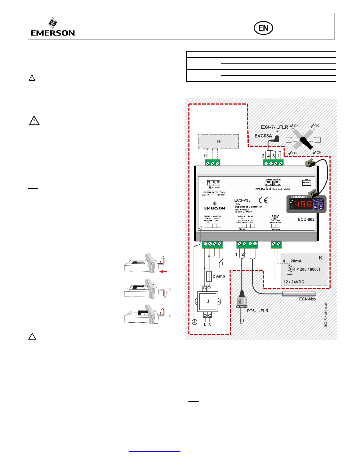
• Refer to the electrical wiring diagram for electrical connections.
• Do not apply voltage to the controller before completion of wiring.
• Ground the metal housing with a 6.3 mm spade connector.
• Keep controller and sensor wiring well separated from mains wiring.
Minimum recommended distance 30 mm!
• Ensure that cables are not mounted near sharp edges.
• Use a class II category transformer for 24 VAC power supply. Do not ground the
24 VAC lines. We recommend using individual transformers for EC3 controller(s)
and for 3
rd
party controllers t o avoid poss ible in terference or grounding problems
in the power supply.
• Connecting any EC3 inputs to mains voltage will permanen tly damage the EC3.
• The use of the relay is essential to protect the system in case of power failure if the
communications interface or the ECD-002 are not utilized.
• If the output relay is not utilized, the user must ensure appropriate safety pre-
cautions are in place to protect the system against damage caused by a power
failure.
• In order to provide system protection in the event of power loss, it is recommended
to change the battery annually.
Digital input status is dependent to operation of compressor/th ermostat
Commander
Operating condition
Digital input (I)
Compressor
Compressor starts
Closed / 24 V (Start)
Compressor stops
Open / 0 V (Stop)
Thermostat
Demand (compressor must be ON)
Closed / 24 V (Start)
No demand
Open / 0 V (Stop)
Wiring:
v
2: White wire 4: Black wire 3: Blue wire 1: Brown wire
G: Remote control panel, system controller
H: Alarm relay, dry contact. Relay coil is not energized at alarm or power off.
I: Digital input (0V/open = Stop; 24 V/closed = Start)
J: Transformer Class II, 24 VAC secondary / 25 VA
K: Third party controller (can use the analog output signal from EC3)
Preparation for Start-up:
• Vacuum the en tire refrigeration system
• Note: EX4-7-…FLR are d elivered at half op en position. Do not ch arge system
before closur e of valve.
• Apply suppl y voltage 24 V to EC3 while the dig ital input is 0 V (open). The valve
will be driven to close position.
• After closure of valve, start to charge the system with refrigerant.
• Start the system and check the superheat and operating conditions.
!
Non-explosiv
environment
Page 2

Operating instruction
EC3-P33 Superheat Controller and
ECD-002 Keypad / Display Unit
Installation in non explosive environment
Emerson Climate Technologies GmbH www.emersonclimate.eu
Am Borsigturm 31 I 13507 Berlin I Germany Date: 04.05.2017 EC3-P33_OI_ML_R01_865919.docx
ECD-002 display/keypad unit: (LE Ds and button functio ns)
Setup of main para meters u sing ECD-002:
(need to be checked/modified before start-up)
• Make sure that digi tal input is 0 V (open). Turn the power supply ON.
• Important: Three ma in pa r am et ers i.e. r efri g era n t t yp e (u0 ) , p ress u re s en sor t ype
(uP) and valve type (ut) can be set only when digital input is open (0 V) while the
power supply is ON (24 V). This feature i s for added safet y to p revent acc iden tal
damage of compressors and other system components.
• For easy sett ing of main parameters, fo llow the pictorial pr ocedure of “Quick
start-up” on the attached individual p a pe r.
• Once the main parameters have been selected/saved the EC3 is ready for
startup. All other parameters can be modified at any time during operation
or standby if it is necessary.
Procedure for parameters modification using ECD-002:
• The parameters can be accessed via the 4-button keypad. The configuration
parameters are protected by a numerical password. The default password is “12”.
To select the parameter configuration:
• Press the PRG button for more than 5 seconds. A flashing “0” i s displaye d
• Press or until “12” is displayed; (password)
• Press SEL to confirm password
• Press or to show the code of the param eter that has to b e changed;
• Press SEL to display the selected param eter value;
• Press or to increas e o r decrease the value;
• Press SEL to temporarily confirm the new value and display its code;
• Repeat the procedure from the beginning "press or to show..."
• To exit and save the new settings: P
ress PRG to confirm the new values and exit
the parameters modification procedure.
• To exit without modifying any parameters: Do not press any button for at least
60 seconds (TIME OUT).
Reset all parameters to factory setting:
• Make sure that digi tal input is 0 V (open).
• Press and together for more than 5 seconds. A fl a sh ing “ 0 ” i s di splayed.
• Press or until the passw o rd is displayed (Factory setting = 12).
If password was changed, select the new password.
• Press SEL to confirm password
“0” is displayed.
• Press SEL to reset all parameters to factory setting
• Press PRG to activat e the function and leave the special function mod e.
Control (valve) start-up behavior: (Parameter uu and u9)
EX4/5/6-…FLR ≤ 1.5 seconds
EX7-…FLR ≤ 3.2 seconds
Main parameters:
(must be checked and modified if necessary)
Code Parameter description and choices Min Max
Factory
setting
Field
setting
H5
Password
1
199
12 u0
System refrigerant
0 6 0
0 = R290; 1 = R32; 2 = R1234ze;
3 = R1234yf; 4 = R1270;
5 = R227; 6 = R600a
uP
Installed pressure sensor type
PT5-30L-FLR
ut
Installed valve type
0 3 1
0=EX4-…FLR; 1=EX5-…FLR;
2=EX6-…FLR; 3=EX7-…FLR
Optional paramete rs:
(recomm e n d ed factory setting fo r majority of app l i c at ions)
After selecting the parameters the EC3-P33 is fully functional without
keypad/display unit. ECD-002 may be removed or connected at any time.
Code Parameter description and choices Min Max
Factory
setting
Field
setting
uu
Start valve opening (%)
5
100
10 u9
Start opening duration (second)
1
120 5
uL
Low superheat alarm function
0 2 1
0 = disable (for flooded evaporator)
1 = enable aut o reset
2 = enable manual reset
Cut-out at 0.5K (if it maintains 1 min.); Cut-in immediately at 3K
u5
Superheat set-point (K)
If uL enabled (auto or manual)
If uL disabled
3
0.5
30
30
6
6
u2
MOP function
0 1 1
0 = disable
1 = enable
u3
MOP set-point (°C) saturation temper atur e
* * X
Factory setting is ac cording to selected refrigerant (u0):
+13°C for R290 +15 °C for R32
+15°C for R1234ze +15°C for R1234 yf
+13°C for R1270 +15°C for R227
+15°C for R600a
┌┘5
Units conversion (only for u3, u5, ┌┘1)
0 1 0
0 = °C, K, bar
1 = °F, R, psig
(Psig values are divided by 10. Example: Display 12.5 is 125 psig)
┌┘
1
Value to show
0 4 0
0 = Measuredsuperheat (K)
1 = Measured evaporating pressure, (bar);
2 = Valve opening (%)
3 = Measured coil-out temperature (°C)
4 = Calculated evaporating temperature (°C) from the pressure
u4
Superheat control mod e
0 1 0
0 = Standard,
1 = Slow
b1
Battery error management, when battery is
defective, see below
0 3 2
value
Alarm
display
Alarm relay Valve
Reset possibility after
recovery/replacement
0 - - Regulating
-
1
Ab - Regulating
-
2
Ab
Signalling
Fully close
Auto
3 Ab
(blinking)
Signalling
Fully close
Manual
When setting b1 to option 0 or 1, the user must ensure appropriate safety
precautions are in place to protect the system against damage c
aused by
a power failure.
!
Blinking: valve is closing
ON: valve is fully close
Blinking: valve is opening
ON: valve is fully open
ON: demand
OFF: no demand
ON: alarm
OFF: no alarm
Parameters setting/saving
Selecting/confirming
Next param eter/
value (higher)
Next param eter/
value (lower)
Prg&Sel (5 sec)
Manual reset f o r
blinking alarm codes
Sec.
uu
u9
%
EC3-X3 BA.cdr
Page 3
Operating instruction
EC3-P33 Superheat Controller and
ECD-002 Keypad / Display Unit
Installation in non explosive environment
Emerson Climate Technologies GmbH www.emersonclimate.eu
Am Borsigturm 31 I 13507 Berlin I Germany Date: 04.05.2017 EC3-P33_OI_ML_R01_865919.docx
Error/Alarm handling:
Alarm code Description
Related
parameter
Alarm
relay
Valve What to do?
Requires manual
reset after resolvin g
alarm
E0
Pressure
transmitter error
- Signalling Fully close Check wiring connection and measure the signal 4…20 mA No
E1
Temperature
sensor error
- Signalling Fully close Check wiring connection and measur e the resistance of sensor No
AΠ
EXV electrical
connection error
- Signalling - Check wiring connection and measure the resistance of winding No
AL
Low superheat
(<0,5K)
uL: 1
Signalling
Fully close
Check wiring connect ion and operation of valve
No
AL blinking
uL: 2
Signalling
Fully close
Yes
Ab
Battery error
b1: 1 - Regulating
Battery potentia lly does not have enough charge to close valve in
case of main power supply interruption. May occur temporarily with
new controllers or after lon g s torage but should disap pear when
battery is charged sufficiently. If Ab remains active even when
battery is c harged, battery may be defective and should be replaced.
(Replacement kit: 807790).
-
Ab
b1: 2 Signalling Fully close -
Ab blinking
b1: 3 Signalling Fully close Yes
Er
Data error display
- out of range
- - -
Data send to the display is out of range. Check temperature and
pressure sensor.
No
---
No data to display
- - -
Check Cable and plug connection between EC3-X33 and ECD-002.
No
Note: When multiple alarms occ ur , the highest prio r ity alarm is displ a yed until being cleared, then the next highest a l ar m is displayed until all alarms are cleared. Only then
will parameters be shown again.
Checking system ope rating conditions:
The data to be permanently shown on the display can be selected by the user
(parameter ┌┘1). It is possible to temporarily display other values. However this
function is not avail a bl e in an ala r m condition. The dis play wil l s how for one s econd
the numerical identifier of the data (see ┌┘1 parameter) and then the selected data.
After 5 minutes, the display will return to the value selected by parameter┌┘1.
Service / Troubleshooting:
Symptom Cause Action
Operating superheat is several degrees higher or lower
than set-point
Incorrect signal from pressure or
temperature sensors
1- Check the sensors
2- Make sure EC N -N6 0 temperature sensor is used
3- For optimum accuracy, please use: PT5-30L-FLR
4- Make sure the s ensor cables are not installed along with other
high voltage cables
Operating superhea t is too low i.e. compressor wet
running
1- Incorrect wiring of ECV05A
2- Defective sensors
1- Check the wiring
2- Check the sensor
Valve is not full y clo sed
1- The digital input is ON (24 V)
2- Wrong setting of paramet er ut.
1- Valve is shut off only when the digital input is turned off (0 V)
2- Check the set t ing of paramet er ut
Instable superheat (hunting)
Evaporator is designed to operate at
higher superheat
Increase th e superheat set-point
Valve opens when EC3 commands to close and vice versa
Wrong wiring between EC3-P33 and
valve
Correct the wiring
Superheat set-point is shifting after severa l m onths of
uninterrupted op eration or permanent jumper of 24 V
digital input
Stepper motor driven valves require
synchronization
Do not apply permanent 24V digital input. Interrupt digital input
once every week for 5 seconds if compressor never stops.
Technical data Dimensions [mm]:
Power supply
24 VAC ±10%; 50/60 Hz; 1 A
EC3-P3
3
Power consumption
25 VA max.
including EX4-7-…FLR.
Plug-in connector
Removable screw terminals wire size 0.14…1.5 mm2
Grounding
6.3 mm spade earth connector
Protection class
IP20 Connection to ECD-002
ECC-Nxx or CAT5 cable with RJ45 connectors
Digital Inputs
0/24VAC/DC for stop/start function
NTC input
EMERSON temperature sensor ECN-N60
4…20 mA Analog input EMERSON PT5-30L-FLR Pressure Tran smitter
4-20 mA Analog output
Deviation from input
signal
For connection to any 3rd party controller with
12/24 VDC power suppl y and appropria te burden
±8% max
ECD-002
Output alarm relay
SPDT contacts 24 VAC/DC, 2 Amp inductive load
Activated:
During normal operation (no alarm condition)
Deactivated:
During alarm condition or power supply is OFF
Stepper motor output for
EX4-7
Maximum cur r ent 0.8 A with nominal 24 VDC
operating voltage
Ambient temperature
range
0…+60°C
+1…+25°C (for best battery life t ime)
> 35°C battery life time < 2 years
Marking
Page 4

Betriebsanleitung
EC3-P33 Überhitzungsregler mit
ECD-002 Anzeige- / Einstelleinheit
Installation in nicht explosionsgefährdeter Umgebung
Emerson Climate Technologies GmbH www.emersonclimate.eu
Am Borsigturm 31 I 13507 Berlin I Germany Date: 04.03.2017 EC3-P33_OI_ML_R01_865919.docx
Beschreibung:
Der Überhitzungsregler EC3-X33 steuert in Anlagen mit flammbaren Kältemitteln
(A2L/A3) EMERSON EX4-7-…FLR Ventile mittels M12 Steckerverbindung
EVC05A.
Hinweis: Dieses Dok umen t enthält für erfahren e An wender eine Kurza nleitun g.
Warnung:
• EC3-P33 hat eine potentielle Zündquelle und entspricht nicht den ATEX
Bestimmungen. Installation nur in nicht explosionsgefährde ter Umgebung.
• EX4-7…FLR sind derzeit für das Kältemittel R290 zugelassen. Andere
aufgeführte Kältemittel unterliegen einer späteren Freigabe. Die Garantie
oder Produkthaftung werden ausgeschlossen, wenn EX4-7-…FLR Ventile
unter anderen Kä ltem itten in der Softw are von EXD-P33 gespeichert werden.
Sicherheitshinweise:
• Lesen Sie die Betriebsanleitung gründlich. Nichtbeachtung kann zum
Versagen oder zur Zerstörung des Gerätes und zu Verletzungen führen.
• Der Einbau darf gemäß EN 13313 nur von Fachkräften vorgenommen
werden.
• Die Anlage ist von außen gut sichtbar mit dem verwendeten Kältemittel und
einer Warnung vor erhöhtem Explosionsrisiko zu kennzeichnen.
• Die angegebenen Grenzwerte für Temperatur (max. +60°C), Strom und
Spannung nicht überschreiten.
• Vor Installation oder Wartung sind die Anlage und das Bauteil spannungsfrei
zu schalten.
• Das Ventil nicht betreiben, wenn der Kompressor nicht läuft.
• Für den gesamten elektrischen Anschluss sind die länderspezifischen
Vorschriften einzuh a lt en.
Hinweis: EC3-P33 R egler enth alten einen wieder au fladbaren Blei -Gel-Akku, der
nicht im normalen Haus- oder Gewerbemü ll entsorgt werden darf. Er muss gemäß
Batteriev erordnung dem hierfür vorgesehenen Entsor g u n g s s ystem zug e führt werden
(Umsetzung d er 2012/19/EU in n ationales Recht) . Weitere Informa tionen er halten
Sie beim für Ihre Stadt zuständigen Recyclinghof.
Einbauort:
EC3-P33 sind für die Montage auf Standard DIN-Schienen geeignet.
Montageposition: Auf senkrechten Flächen, mit dem Motoranschluss nach oben.
Dauerhafte Montage der Anzeigeeinheit ECD-002:
• ECD-002 kann jederzeit montiert werden, auch währ end dem Betrieb .
• Die Anzeigeeinheit ECD-002 wird in Frontplatt e n m it
einem Ausschnitt von 71x29 mm montiert.
• Anzeigeeinheit vors
ichtig mit eingefahrenen
Halterungen in den Frontplattenausschnitt ein
schieben
(1).
•
Beiliegenden Imbusschlüssel in die Löcher auf der
Frontseite einstecken und im Uhrzeigersinn drehen. Die
Halterungen treten aus dem Gehäuse herv
or und
bewegen sich in Richtung Frontplatte (2).
•
Imbusschraube drehen bis die erste Halterung die
Frontplatte leicht berührt. Dann zweite Halterung in
diese Position bringen (3).
• Beide Seit en g leichmäßig und nicht zu fest anziehen.
Hinweis: durch zu festes Anziehen können d ie
Halterungen abbrechen.
Elektrischer Anschluss:
• Den elektrischen Anschluss gem. Verdrahtungsschema durchführen!
• Versorgungsspann u ng ers t n ach kompletter Installat i on anl eg en!
• Gehäuse mit einem 6.3 mm Flachstecker erden!
• Signalleitungen und Leitungen mit Netzspannung in getrennten
Kabelschächten verlegen, Mindestabstand 30 mm!
• Kabel so verlegen, dass sie nicht an scharfen Kanten beschädigt werden.
• Für die 24 V Stromversorgung sind ausschli eßlich Transfor matoren der Klasse I I
zu verwenden. Die 24V L eitu ngen dür fen ni cht g ee rdet w e rden. Wir empf ehle n die
Verwendun g jeweils sepa rater EMERSON Transforma toren fü r EC3 Regler und
die Regler anderer Hersteller, weil unter Umständen über die Erdleitungen
Kurzschl üs s e e nts tehen können.
• Vor der Inbetriebnahme des EC3 müssen die Haupt-Parameter ein ges t ellt un d der
24 V-Digital eingang darf n icht am EC3 ang e s c hl ossen wer de n.
• Das Alarmrelais dient zum Schutz des Systems bei Stromausfall, wenn
Kommunikations-Schnittstelle oder ECD-002 nicht verwendet werden!
• Wird das Alarmrelais nicht verwendet, muss das System auf andere Weise vor
Schäden durch Stromausfall geschützt werden.
• Um das System vor Schäden durch Stromausfall zu schützen empfehlen wir einen
jährlichen Austausch des Akkus.
Funktion des Digitaleingangs bei Verdichter- oder Therm ost at-Betrieb:
Befehlsgeber
Betriebszustand
Digitaleingang
Verdichter
Verdichter startet
zu / 24 V (Start )
Verdichter stoppt
offen / 0 V (Stopp)
Thermostat
Anforderung (Verdichter Ein)
zu / 24 V (Start )
Keine Anforderung
offen / 0 V (Stopp)
Verdrahtung:
Kabelfarben: 2: Weiß 4: Schwarz 3: Blau 1: Braun
G: Schaltschrank, Anlagenregler
H: Alarmrelais, Wechsler. Inaktiv bei Alarm oder fehlender Stromversorgung
I: Digitaleingang (0V = Aus; 24 V = Ein)
J: Trafo Klasse II, 24 VAC Sekundär/ 25 VA
K: Anlagenregler (kann analoges Ausgangssignal von EC3 benutzen)
Vorbereitungen f ür Inbetriebnahme:
• Den gesamten Kältekreislauf vakuumieren.
• Hinweis: EX4-7-…FLR werden halbgeöffnet ausgeliefert. Den Kältekreislauf nur
bei geschlossenem Ventil mit Kältemittel füllen.
• Versorgungsspannung 24 V zu EC3 einschalten, der Digitaleingang bleibt bei 0 V.
Das Ventil wird zugefahren.
• Bei geschlossenem Ventil System mit Kältemittel füllen.
• System starten, Überhitzung und Betriebsbedingungen überprüfen.
!
Nicht explosions-
gefährdete Umgebung
Page 5

Betriebsanleitung
EC3-P33 Überhitzungsregler mit
ECD-002 Anzeige- / Einstelleinheit
Installation in nicht explosionsgefährdeter Umgebung
Emerson Climate Technologies GmbH www.emersonclimate.eu
Am Borsigturm 31 I 13507 Berlin I Germany Date: 04.03.2017 EC3-P33_OI_ML_R01_865919.docx
ECD-002 Anzeige einheit: (Funktion der LEDs und Tasten)
Einstellung der Ha upt-Parameter mit ECD-002
(vor der ersten Inbetriebnahme prüfen bzw. anpassen)
• Während am Digitaleingang 0 V anliegen Versorgungsspannung einschalten.
• Wichtig: Die drei Parameter Kältemi ttel ( u0), Dru cksen sor-Typ (uP) und Ventil-
Typ (ut) können nur eingestellt werden, wenn der Digitaleingang AUS (0 V) und
die Verso r g ungsspannung AN (24 V) ist. Diese Sicherheitsf u nktion verhind ert die
Beschädigung des Verdichters oder anderer S ystemkomponenten.
• Zu m einfachen Einstellen der Parameter gibt es ein e Schnellstart-Anleitung mit
Bildern (s. separate Seite).
• Nach Einst el l ung de r H a upt-Parameter und aktivieren des Digitaleingangs sind die
EC3-P33-Regler betri ebsbereit. Alle and eren Parameter können jederzeit, auch
während des Betriebs oder im Standby angepasst werden.
Parametereinstellung mit der Anzeigeeinheit ECD-002:
• Parameteränderungen sind mit der Gerätetastatur möglich. Die Konfigurations-
parameter s in d pa ss wort ges ch ü t zt. Das werk s s eit i g ei n ges t ellt e Pa ss wor t i s t “1 2 ” .
Zur Auswahl der Parametereinstellungen:
• PRG Taste län ger als 5 Sek. gedrü ckt halten, ein e blinkende "0" er scheint
• oder Taste drücken bis Passwort (Standardwert 12) angezeigt wird
• SEL drücken - Passwort wird bestätigt
• oder Taste drücken bis der gewünschte Parameter erscheint;
• SEL drücken - der aktuell eingestellte Wert wird angezeigt
• oder Taste drücken - der Wert wird vergrößert oder verkleinert
• SEL drücken - der eingestellt e Wert wird vorläufi g behalten, muss aber n och
gespeicher t werden. Die Parameterkennung wird wieder an gezeigt.
• Zur Änderung weiterer Parameter wird dieser Ablauf wiederholt:
• oder Taste drücken - nächste Param eterkenn ung a u s wählen.
• Parameter speichern und Konfigurationsmodus beenden: PRG Taste drücken
• Parameter nicht speichern und Konfigurationsmodus ohne Parameter-
änderung beenden: Mindestens 60s lang keine Taste drücken (Zeitsperre)
Parameter auf Werkseinstellung zurücksetzen:
• und Taste länger als 5 Sek. gedrückt halten bis blinkende "0" erscheint
• oder Taste drücken bis das Passwort (Standardwert 12) angezeigt wird
• SEL drücken - Passwort wird bestätigt, “0” wird angezei g t
• SEL drücken - alle Parameter werden auf Werkseinstellung zurückges etzt
• PRG drücken - die gewählte Funktion wird aktiviert und die Betriebsart Spezial-
funktionen verlassen
Startverhalten der Regelventile: (Parameter uu und u9)
EX4/5/6-…FLR ≤ 1,5 Sekunden
EX7-…FLR ≤ 3,2 Sekunden
Haupt-Parameter:
(müssen ggf. angepasst werden)
Code Beschreibung und Wahlmöglichkeiten Min Max Werk Kunde
H5
Passwort
1
199
12
u0
Kältemittel
0 6 0
0 = R290; 1 = R32; 2 = R1234ze;
3 = R1234yf; 4 = R1270;
5 = R227; 6 = R600a
uP
Installierter Drucktransmitter
PT5-30L-FLR
ut
Installier te s EMERS O N Re gelventil
0 3 1
0 = EX4-…FLR 1 = EX5-…FLR
2 = EX6-…FLR 3 = EX7-…FLR
Sonstige Parameter:
(Anpassung nur für spezielle Anwendungen)
EC3-P33 sind auch ohne Anzeigeeinheit ECD-002 betri ebsbereit, dies e kann auch
während des Betriebs ein- o der ausgesteckt werden.
Code Beschreibung und Wahlmöglichkeiten Min Max Werk Kunde
uu
Startöffnung des Regelventils (%)
5
100
10 u9
Startzeit für Ventilöffnung (Sekunden)
1
120 5
uL
Alarm bei zu niedriger Überhitzung
0 2 1
0 = deaktiviert (für überfluteten Verdampfer)
1 = automat. Rückstellung
2 = manueller Rückstellung
Alarm Ein bei 0.5K (wenn länger als 1 Minute unterschritten);
Alarm Aus bei 3K (ohne Zeitverzug)
u5
Überhitzungseinstellung (K)
wenn uL aktiviert (autom. oder manuell)
wenn uL deaktiviert
3
0.5
30
30
6
6
u2
MOP Funktion
0 1 1
0 = deaktiviert
1 = aktiviert
u3
MOP (°C) Sättigungstemperatur
* * X
Werkseinstellung abhängig vom gewählten Kältemittel (u0):
+13°C for R290 +15 °C for R32
+15°C for R1234ze +15°C for R1234 yf
+13°C for R1270 +15°C for R227
+15°C for R600a
┌┘5
Einheiten (nur für u3, u5, ┌┘1)
0 1 0
0 = °C, K, bar
1 = °F, R, psig
(Psig Werte geteilt durch 10. Bsp: Display 12.5 bedeutet 125 psig)
┌┘
1
Angezeigter Wert
0 4 0
0 = gemess. Überhitzung (K)
1 = gemessener Verdampfungsdruck (bar)
2 = Ventilöffnungsgrad (%)
3 = gemessene Sa uggas-Temperatur (°C)
4 = aus gemessenem Druck errechnete Verdampfu ngstemperatur (°C)
u4
Überhitzungsregelung (nach 01. 03 . 0 8)
0 = Standard,
1 = langsam
0 1 0
b1
Batterie-Fehlermanagement bei defekter
Batterie
0 3 2
Wert
Display-
Anzeige Alarmrelais Ventilzustand
Möglichkeit zur
Rückstellung nach
Erholung/Austausch
0 - - regelt
-
1
Ab - regelt
-
2
Ab
signalisierend
geschlossen
automatisch
3 Ab
(blinkt)
signalisierend
geschlossen
manuell
Wird das Alarmrelais nicht verwendet (b1 = 0 oder = 1), muss das
System auf andere Weise vor Schäden durch Stromausfall geschützt
werden
!
Sec.
uu
u9
%
EC3-X3 BA.cdr
Blinkt: Ventil schliesst
AN: Ventil ist geschlossen
Blinkt: Ventil öffnet
AN: Ventil ist offen
Parameter Ei ngabe/Speicherung
Nächster Parameter/Wert (höher)
AN: Anforderung
AUS
: keine
Anford.
AN: Alarm
AUS: kein
auswählen/bestätigen
Nächster Parameter/Wert (tiefer)
Manuelle Rückstellung für
alle blinkenden Alarme
(PRG & SEL) 5s drücken
Page 6

Betriebsanleitung
EC3-P33 Überhitzungsregler mit
ECD-002 Anzeige- / Einstelleinheit
Installation in nicht explosionsgefährdeter Umgebung
Emerson Climate Technologies GmbH www.emersonclimate.eu
Am Borsigturm 31 I 13507 Berlin I Germany Date: 04.03.2017 EC3-P33_OI_ML_R01_865919.docx
Alarmanzeigen und Fe hlerbehebung:
Alarm
Code
Fehler
Beschreibung
Abhängiger
Parameter
Alarm
Relais
Ventil-
zustand
Fehlerlösung
Man. Rückstellung
nach Fehlerbehebung
notwendig
E0
Drucktransmitter
Fehler
- signalisierend geschlossen Verdrahtung prüfen und 4…20 mA Signal mess en Nein
E1
Temperatursensor
Fehler
- signalisierend geschlossen Verdrahtung prüfen und Widerstand des Sensors messen Nein
AΠ
EXV Fehler elektr.
Anschluss
- signalisierend unbekannt Verdrahtung prüfen und Widerstand der Wicklung messen Nein
AL
Überhitzung zu
niedrig (<0,5K)
uL: 1
signalisierend
geschlossen
Verdrahtung prüfen und Funktionsprüfung des Ventils
durchführen
Nein
AL blinkt
uL: 2
signalisierend
geschlossen
Ja
Ab
Batteriefehler
b1: 1 - regelt
Batterieladung zu schwach für Schließen des Ventils bei
Stromausfall. Kann bei neuen Reglern oder langer Lagerzeit
auftreten und sollte nach ausreichender Aufladung der Batterie
verschwinden. Ansonsten defekte Batteri e er setzen
(Austauschkit Bestell-Nr. 807790).
-
Ab
b1: 2 signalisierend geschlossen -
Ab blinkt
b1: 3 signalisierend geschlossen Ja
Er
Daten außerhalb
Anzeigebereich
- - -
Display kann Daten nicht darstellen, Einstellwert der Parameter
verändern.
Nein
---
Keine Daten auf
dem Display
- - -
Kabel- und Steckerve r bin dungen zwis chen EC3-P33 und ECD002 prüfen
Nein
Hinweis: Bei mehreren Alarmen gl eichzeitig wi rd der Alarm mit der höchsten Priorität angezeigt, nach dessen Beseitigung wird d er n ächsthöhere angezeigt usw., bis alle
Alarme beseitigt sind. Danach werden wieder die Parameter angezeigt
Überprüfung der Be triebsbedingungen:
Die am Display permanent angezeigten Daten werden vom Anwender durch Parameter
┌┘1 bestimmt. Gleichz eitig können andere Daten vorübe rgehend am Dis play angezeigt werden,
sofern kein Alarm vorl ieg t. Das Displ ay zeig t nach Dr ücken vo n SEL z uers t für 1 Se kunde den Code für den jewe ilige n Wer t (s . Parame ter
┌┘1) und dann die Date n. Nac h 5 Minute n
werden wieder die permanenten Daten angezeigt.
Service / Fehlersuche:
Fehlerbeschreibung Ursache Aktion
Überhitzung ist einige Grad höher oder niedriger als der
Einstellwert
Fehlerhaftes Signa l von Druck- oder
Temperatursensoren
1- Sensoren überprüfen.
2- ECN-N60 als Temperatursen sor einsetzen.
3- EMERSON Drucktransmitter verw enden: PT5-30L-FLR
4- Sensorkabel nicht zusammen mit stromführenden Leitungen
verlegen.
Überhitzung ist zu niedrig, Verdichter läuft nass
1- Ventile falsch angeschlos sen
2- Defekter Sensor
1- Verdraht ung ü b e r prüfen.
2- Sensor überprüfen.
Ventil ist nicht vollständig geschlossen
1- Digitaleingang ist EIN (24 V)
2- Falsche Einstellung für Parameter ut
1- Ventil schließt nur, wenn der Digitaleing ang A US ist (0 V).
2- Einstellung für Parameter ut überprüfen.
Schwankende Überhitzung
Eingesetzter Verdampfer ist für
höhere Überhitzung ausgelegt
Einstellwert für Überhitzung Vergrößern.
Ventil öffnet, wenn EC3 Befehl zum Schließen gibt
und umgekehr t
Fehlerhafte Verdrahtung zwischen
EC3-P33 und Ventil
Verdrahtung gem. Verdrahtungsschema durchführen.
Überhitzungseinstellung verändert sich nach einigen
Monaten ununterbrochenen Betriebs oder bei Permanenter-
überbrücku ng des 24 V Digitaleingangs
Ventile mit Schrittmotor erfordern
Synchronisation
Am 24 V Digitaleingang nicht dauerhaft Spannung anlegen; wenn
Verdichter ununterbrochen läuft Digitaleingang einmal je Woche
für 5 Sekunden unterbrechen.
Technische Daten: Abmessungen [mm]:
Versorgungsspannung
24 VAC ±10%; 50/60 Hz; 1 A
EC3-P33
Leistungsaufnahme
25 VA max, inklusive EX4-7…FLR
Anschlüsse
Steckbare Schraubklemmen für Adern mit max.
0,14…1,5 mm2 Querschnitt
Erdungsanschluss
für 6.3 mm Flachstecker
Schutzklasse
IP20 Verbindung z u EC D -002
ECC-Nxx oder CAT5 Kabel mit RJ45 Anschlüssen
Digitaleingänge
0/24 VAC/DC zum Ein- bzw. Ausschalten
NTC Analogeingang
EMERSON Temperatur sensor ECN-N60
4-20 mA Analogeingang
EMERSON P T5-30L-FLR Drucktransmitter
4…20 mA Analogausgang
Abweichung vom
Eingangssignal
für externen Regler mit 12/24 VDC
Speisespannung & geeignetem internen Widerstand
± 8% max.
ECD-002
Ausgang Alarmrelais
Wechsler (geeignet für 24 VAC/DC),
Induktive Last: 2 A
Aktiviert:
Bei Normalb etrieb (kein Alarm zustand)
Inaktiviert:
im Alarmzustand oder bei ab g eschalteter Sp annung
Schrittmotorausgang für
EX4-7
Maximalstrom 0,8 A mit nominal 24 VDC
Betriebsspannung
Temperaturbereich
0…+60°C
+1…+25°C (für optimale Batterielebens d auer)
> 35°C Batter ielebensdauer < 2 Jahre
Kennzeichnung
Page 7

EC3-P33 Superheat Controller and ECD-002
Keypad / Display Unit
Emerson Climate Technologies GmbH www.emersonclimate.eu
Am Borsigturm 31 I 13507 Berlin I Germany Date: 04.03.2017 EC3-P33_OI_ML_R01_865919.docx
2
2a
2b
0 = R290 4 = R1270
1 = R32 5 = R227
2 = R123ze 6 = 600a
3 = R123yf
2
3 3a
3b
PT5-30L-FLR (R290)
3c
4
4a
4b
0 = EX4-…FLR
1 = EX5-…FLR
2 = EX6-…FLR
3 = EX7-…FLR
4c 4d
4e
Display of Data:
0
1
1a
1b
1c
1d
1e
EX7-…FLR
5 sec.
1-199
88
12x
EX4, EX5
EX6, EX7
EX8
Po => To
Ts
Vo (%)
Ts (°C)
To (°C)
SH = Ts - To (K)
100%
0%
Po (barg)
EC
3
X_
65
1
30
.c
d
r
R22
 Loading...