

Page 1

Operating instruction
• ECD-002 can be mounted in panels with 71x29
Turn Allen key until mounting lug barely touches
panel. Then move other mounting lug to the same
will break easily.
Commander
Operating condition
Digital input (I)
Compressor
Compressor starts
Closed / 24 V (Start)
Compressor stops
Open / 0 V (Stop)
Thermostat
Demand (compressor must be ON)
Closed / 24 V (Start)
No demand
Open / 0 V (Stop)
!
EC3-X32 Superheat Controller with TCP/IP
General information:
EC3-X32 is the superheat controller with TCP/IP connection for stepper motor driven
EMERSON Electrical Control Valves EX4...EX8 and FX5…FX9.
Safety ins tructions:
• Read operat ing i nstruct ions t horou ghly. Failu re to c omp ly can r esult in device
failure, system damage or personal injury.
• According to EN 13313 it is intended for use by persons having the
appropriate knowledge and skill.
• Do not exceed the specified maximum ratings for pressure, temperature,
voltage and current.
• Before installation or service disconnect all voltages from system and device.
• Do not operate system before all cable connections are completed.
• Entire elec t rical connections have to comply with local regulations.
Note: The EC3 -X32 series contains a VRLA battery = valve regulated rec ha rg eab le
lead-acid battery. The batter y mus t NOT be dis posed o f with o ther comme rcial waste .
Instead, it is the us er ’s r e sponsi bil ity to pass it to a des ig nate d col l ectio n po int f or the
safe recycling of batteries (harmonized directive 2012/19/EU). For further
information contac t your local environmenta l recycling center.
Mounting positio n:
The EC3-X32 is designed to be mounted onto a standard DIN rail. Mounting
position: on vertical walls, with stepper motor connector on top side only.
Mounting of ECD-002:
• ECD-002 can be installed at any time also during operation.
communication capability
Wiring:
mm cutout.
• Push controller in to panel cut-out.(1)
• Make sure that mounting lugs are flush with
outside of controller housing
• Insert Allen key into front panel holes and turn
clockwise. Mounti ng lugs will turn and graduall y
move towards panel (2)
•
position (3)
• Tighten both sides very carefully until keypad is
secured. Do not over ti ghten as mounting lugs
Electrical Installation:
• Refer to the electrical wiring diagram for electrical connections.
• Do not apply voltage to the controller before completi on of wiring.
• Ground the metal housing with a 6.3 mm spade connector.
• Keep controller and sensor wiring well separated from mains wiring. Minimum
recommended distance 30 mm.
• Use a class II category transformer for 24VAC power supply. Do not ground the
24VAC lin es. We recommend using individual transformers for EC3 con troller(s)
rd
and for 3
party contr ollers to avoi d pos sible in terferenc e or groun ding p roblems
in the pow er suppl y. Connecting any EC3 inputs to mains voltage will permanently
damage the EC3.
• The use of the relay is essential to protect the system in case of power failure if the
communications interface or the ECD-002 are not ut ilized.
• If the output relay is not utilized, the user must ensure appropriate safety pre-
cautions are in place to protect the system against damage caused by a power
failure.
• In order to provide system protection in the event of power loss, it is recommended
to change the battery annually.
Digital input status is dependent to operation of compressor/th ermostat
A: White wire B: Black wire C: Blue wire D: Brown wi r e
E: M12 Plug cable assembly EXV-Mxx for connection to EX4…EX8 and
FX5…FX9.
G: Remote control panel, system controller.
H: Alarm relay, dry contact. Relay coil is not energized at alarm or power off.
I: Digital input (0V/open = Stop; 24V/closed = Start)
J: Transformer Class II, 24VAC secondary / 25VA
K: Third party controller (can use the analog output signal from EC3)
O: Pump down relay, dry contact. Relay is energized during normal operation.
Preparation for Start -up:
• Vacuum the entire refrigeration system.
• Note: EMERSON Electrical Control Valves EX4…EX8 and FX5…FX9 are
delivered at half open position. Do not charge system b efore closure of v alve.
• Apply supply voltage 24V to EC3 while the digital input is 0V (open). The valve
will be driven to close position.
• After closure of valve, start to charge the system with refrigerant.
• Start the system and check the superheat and operating conditions.
Emerson Climate Technologies GmbH www.emersonclimate.eu
Am Borsigturm 31 I 13507 Berlin I Germany Date: 03.04.2017 EC3-X32_OI_ML_R13_865008.docx
Page 2

Operating instruction
Factory
setting
Field
setting
H5
Password
1
199
12 u0
System refrigerant
0
15 1
0 = R22 1 = R134a 2 = R50 7 3 = R40 4A 4 = R40 7C
12 = R449A 13 = R450A 14 = R513A 15 = R1234ze
uP
Installed pressure sensor type
0 3 0
0 = PT5-07x (for R22 / R134a / R507 / R404A / R407A / R407C /
3 = PT5-50x (for R744)
ut
Installed valve type
1
12 5
1 = EX4 2 = EX5 3 = EX6 4 = EX7
9 = FX7 10 = FX7.5 11 = FX8 12=FX9
uu
Start valve opening ( %)
0
100
50 u9
Start opening duration (second)
0
120 5
uL
Low superheat alarm function
0 2 1
0 = disable (for flooded eva porator)
Cut-out at 0.5K (if it maintains 1 min.); Cut-in immediately at 3K
u5
Superhea t set-point (K)
If uL disabled
0.5
30
6
u2
MOP function
0 1 1
0 = disable 1 = enable
u3
MOP set-point (°C) saturation temperature
* * **
**) Factory setting is according to selected refrigerant (u0):
refrigerant
┌┘5
Units conversion
0 1 0
0 = °C, K, bar 1 = °F, R, psig
(Psig values are divided by 10. Example: Display 12.5 is 125 psig)
1
Value to show
0 4 0
0 = Measured superheat (K) 1 = Measured evaporating pressure, (bar);
4 = Calculat ed evaporating temperature (°C) from the pressure
u4
Superheat control mode
0 2 0
0 = Standard, 1 = Slow, 2 = intermediate control
uH
High superheat alarm function
0 = disable, 1 = enable auto reset
1
uA
High superheat alarm setpoint
16
40
30
ud
High superheat alarm delay, min.
1
15 3
P2
Freeze protection cut -out, °C
-40
40 0
P3
Freeze protection cut -in , °C
-37
43 3
P4
Freeze protection alarm function
2 = enable manual r eset)
0 2 0
P5
Freeze protection alarm delay, sec.
5
199
30
P6
Pump-down function
(0 = disable, 1 = enable auto-reset)
0 1 0
P7
Pump-down cut-out, barg
-0,5
18
0.5 P8
Pump-down time del ay, sec.
0
199
30
P9
Low pressure alarm function
2 = enable manual reset)
0 2 0
PA
Low pressure alarm cut-out, barg
-0,8
17,7 0
Pb
Low pressure alarm delay, sec.
5
199 5
Pd
Low pressure alarm cut-in, barg
-0,5
18
0.3 L2
Output logic
0 3 1
0: Alarm = normal, pump down. = normal
3: Alarm = inverse, pump down. = inverse
Blinking: valve is closing
ON: valve is fully close
Blinking: valve is opening
ON: valve is fully open
ON: demand
ON: alarm
OFF: no alarm
Parameters setting/saving
Selecting/confirming
Next parameter/
Next parameter/
value (lower)
Prg&Sel (5 sec)
blinking alarm codes
EC3-X32 Superheat Controller with TCP/IP
ECD-002 displ ay/keypad unit: (LE Ds and button functions )
OFF: no demand
Blinking: pump
down
Manual reset for
Procedure for parameter modifi cation using ECD-002:
• Note: Some of the functions/parameters (manual control and TCP/IP
configuration) cannot be modified when using ECD-002 comparing to a set-up by
PC via TCP/IP.
• Warning:
All alarms are disabled during manual control. We do not recommend
unattended operation of system during manual control.
• The parameters can be accessed via the 4-button keypad. The configuration
parameters are protected by a numerical password. The default password is “12”.
To select the parameter configuration:
• Press the PRG button for more than 5 seconds, a flashing “0” is displayed
• Press or until “12” is displayed (password)
• Press SEL to confirm password
• Press or to show the code of the parameter that must be chan g ed;
• Press SEL to display the selected parameter value;
• Press or to increase or decrease the value;
• Press SEL to temporarily confirm the new value and display its code;
• Repeat the procedure from the beginning "press or to show..."
• To exit and save the new settings: Press PRG to confirm the new values and exit
the parameters modification procedure.
• To exit without modifying any parameters: Do not press any button for at least
60 seconds (TIME OUT).
Special Function s:
The Special F unctions can be act iv ated by:
• Press and together for more than 5 seconds, a flashing “0” is displayed.
• Press or until the password is displayed (default = “12”).
If password was changed, select the new password.
• Press SEL to confirm password
A “0” is displayed and the Special Function mode is activated.
• Press or to select the function. The number of special functions is dynamic
and controller dependent. See list below.
0: Reset controller to factory settings (this action is possible only when digital
input is 0V i.e . open).
1: Displays the current TCP/IP address.
2: Assign temporary 192.168.1.101 as TCP/IP address if EC3-X32 has different
Address.
• Press SEL to activate the function without leaving the special function mode.
• Press PRG to activate the functio n and leave the special function mode.
communication capability
value (higher)
Main parameters:
(must be checked and modified if necessary)
Code Parameter description and choices Min Max
5 = R410A 6 = R124 7 = R744 (subcritical application)
8 = R407A 9 = R 4 07F 10 = R32* 11 = R448A
R407F / R124 / R448A /R449A / R450A / R513A /
R1234ze)
1 = PT5-18x (for R410A/ R32)
2 = PT5-30x (for R410A / R744 / R32)
5 = EX8 6 = FX5 7 = FX6 8 = FX6.5
1 = enable auto reset 2 = enable manual reset
If uL enabled (auto or man ual)
+13°C - R22 +15°C - R134a +7°C - R507
+7°C - R404A +15°C - R407C +15°C - R410A
+50°C - R124 -5°C - R744 +10°C - R407A
+10°C - R407F +10°C - R32 +12°C - R448A
+12°C - R449A +19°C - R450A +13°C - R513A
+24°C - R1234ze
3
*) Min. and Max . setting values are dependent to select ed type of
┌┘
2 = Valve opening (%) 3 = Measured coil-out temperature (°C)
0 = disable, 1 = enable auto-reset,
(0 = disable, 1 = enable auto-reset,
30
6
1: Alarm = inverse, pump down. = normal
2: Alarm = normal, pump down. = inverse
Emerson Climate Technologies GmbH www.emersonclimate.eu
Am Borsigturm 31 I 13507 Berlin I Germany Date: 03.04.2017 EC3-X32_OI_ML_R13_865008.docx
Page 3

Operating instruction
Factory
setting
Field
setting
b1
Battery error management, when battery is
defective, see below
0 3 2
value
Alarm
display
Alarm relay
Valve
Reset possibility after
recovery/replacement
0 - - Regulating
-
1 Ab - Regulating
-
2 Ab
Signaling
Fully close
Auto
3 Ab
(blinking)
Signaling
Fully close
Manual
When setting b1 to option 0 or 1, the user must ensure appropriate safety
precautions are in p la ce to protect the system against damage c au sed by
a power failure.
uF
Control range valve %
5
100
100
Digital input
status
Alarm
condition
24V (ON)
NO
Activate
0V (OFF)
NO
Deactivate when pressure drops
below P7 and after elapsed time P8
0V or 24V
YES
Deactivate
!
Sec.
uu
u9
%
EC3-X3 BA.cdr
EC3-X32 Superheat Controller with TCP/IP
Code Parameter description and choices Min Max
*) Notes for R32: R32 is classified as low flamm able refrigera nt in Europe. EC3-
X32 is designed under consideration of European safety standards and directives for
none flammable refrigeran ts. Th e use of EC3-X32 with R32 is for systems/regions
which it does not require consideration of additional safety standards as for
flammable refrigerant.
After selecting the parameters the EC3-X32 is f ul ly func tional witho ut con n ec ted P C
or keypad/display unit ECD-002.
Control (valve) start-up behavio r: (Parameter uu and u9 )
communication capability
DHCP server from network/Router. Refer to the TCP/IP Controller-Readme file
if a specific port is required.
• It is possible to identify the dynamic TCP/IP address assigned by DHCP of the
Router or network, refer t o the TCP/IP Controller-Readme file.
• After a few moments, the default monitoring page should be displayed. If the
browser d oes no t open t he defa ult pa ge or displa y activ e data , the us er sho uld c heck
the Internet browser “Option” configuration. Refer to the TCP/IP Controller-
Readme file.
EX4/5/6 ≤ 1.5 seconds
EX7 ≤ 3.2 second s
EX8 ≤ 7.2 seconds
FX5-8 ≤ 7.3 seconds
FX9 ≤ 9.7 seconds
Pump down functio n: (if P6=1 and L2=1)
Pump down relay
Possibilities of connecting EC3-X32 to a network or PC:
• A TCP/IP Controller Readme file is available on the www.emersonclimate.eu
website to provide detailed information about TCP/IP Ethernet connectivity.
Please refer to this file if you need information beyond the contents of this
instruction sheet.
• Connect t he E C3-X32 using the optional ECC-Nxx cable assembly or a standard
CAT5 netw or k cabl e w ith RJ4 5 plug s as se mbl y to a ne two rk o r route r tha t e na ble s
the controller to receive a dynamic TCP/IP address or
• Connect the EC3-X32 to a computer using a crossover cab le plugged directly into
the Ethernet port. In this case, the TCP/IP address of the computer must be
manually modifi ed to be compatible with the default address of the controller.
Refer to the TCP/IP Controller-Readme file for more details.
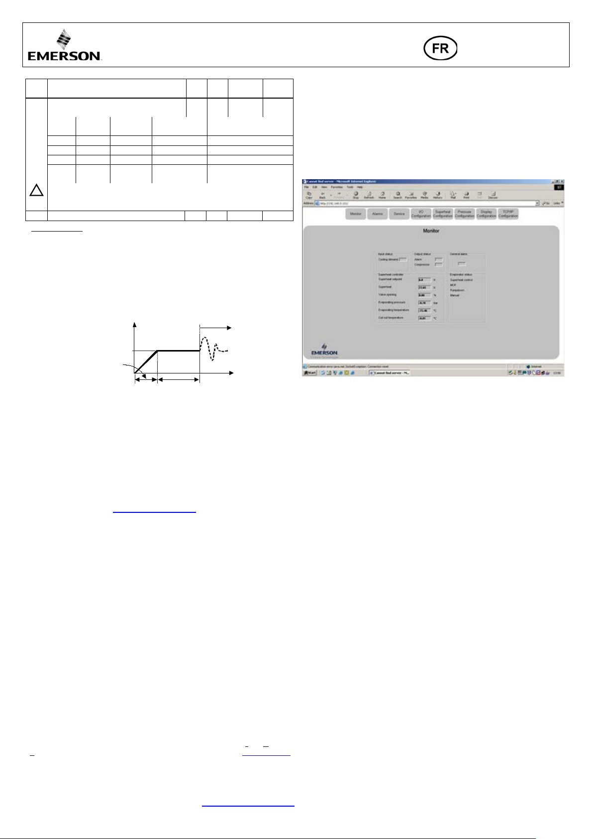
Setting and visualizing Data: WebPages
(recommended method)
• Make sure that digital input is 0V (open), turn the power supply ON.
• Four parameters i.e. refrigerant type (u0), pressure sensor type (uP), valve type (ut)
and control mode can be set only when digital input is open (0V) while the power
supply is ON (24V). This feature is for added safety to prevent accidental damage
of compressors and other system components. All other parameters can be
modified at any time.
• The EC3-X32 has a TCP/IP Ethernet communication interface enabling the
controller t o be di rec tly conn ect ed to a net work or a PC via th e stand ar d Ethern et
port. The EC3-X32 controller has embedded WebPages to enable the user to
visualize t he parameter lists using r eal text labels.
• To view WebPages on the PC, a standard Web Browser like Internet Explor e r® or
Mozilla Firefox and JRE Java Runtime Environment is needed. JRE can be
downloaded at no charge from the www.java.com website.
• Open the Internet browser program on the co m puter and, if EC3-X32 is connected
directly to PC with a crossover cable enter the default TCP/IP address of the
controller (192.168.1.101) into the address line, or the dynamic address from the
• The Monitoring and Alarm WebPages are read only and therefore it is not
necessary to enter a username or password. A username and password will be
requested upon the initi al re quest to any of the other WebPages. The factory default
settings are: Username: “EmersonID”, Password: “12”
• The default settings may be modified on the Display configuration page.
• Press the ta bs at the top of t he Mo nitor ing page with a le ft cl ick o f the mouse bu tton
to enter the respective Web page.
• The paramet ers will b e visualized in real text together with the program code as
defined in the parameter list below.
• After the parameters have been modified, the complete list of settings can be saved
to the memory of the computer a nd used later t o upload into a nother controller.
This can save a considerable amount of time when using multiple controllers and
over a period of time, a library can be created containing the parameter lists for
equipment for different applications.
• It is also possible to display live graphical data from the controller. Superheat,
evaporating pressure, coil-out temperature and evaporating temperature are
available on a 15 minutes rolli ng chart. R efer to the TCP/IP C ontroller-Readme
file for a complete des cription of th e features av ailable for the TC P/IP series o f
controllers.
Emerson Climate Technologies GmbH www.emersonclimate.eu
Am Borsigturm 31 I 13507 Berlin I Germany Date: 03.04.2017 EC3-X32_OI_ML_R13_865008.docx
Page 4

Pressure transmitter
error
Temperature sensor
error
EXV electrical
connection error
Ab
b1: 1
-
Regulating
Battery potentially does not have enough charge to close valve in
replaced. (Replacement kit: 807 790).
-
Ab
b1: 2
Signaling
Fully close
-
Pump down action
accomplished
AF
P4: 1
Signaling
Fully close
No
AF blinking
P4: 2
Signaling
Fully close
Yes
AL
uL: 1
Signaling
Fully close
No
AL
blinking
P9: 1
Signaling
Fully close
No
AP blinking
P9: 2
Signaling
Fully close
Yes
Data error display out of range
Data send to the display is out of range. Check temperature and
pressure sensor.
Check Cable and plug conn ection between EC3-X… and
ECD-002.
Operating superheat is several degrees higher or lower than
Incorrect signal from pressure or
1- Check the sensors.
high voltage c ables
Operating superheat is too low i.e. compressor wet runn ing
1- Incorrect wiring of ECVs
2- Defective sensors
1- Check the wiring
2- Check the sensor
Valve is not fully closed
1- The digital input is ON (24 V)
2- Wrong setting of parameter ut.
1- Valve is shut off only when the digital input is turned off (0 V).
2- Check the setting of parameter ut.
Instable superheat (hunting)
Evaporator is designed to operate at
higher superheat
Increase the superheat set-point.
Valve opens when EC3 comm ands to close and vice versa
Wrong wiring between EC3-X3...
and valve
Correct the wiring.
EX8 is not able to open at hi gh differential pressu r e
Wrong setting of para m eter ut
Check the parameter ut. (Larger valve requires higher torque and
higher current)
Superhea t set-point is shifting after several months of
digital input
Stepper motor driven valv es require
Do not apply permanent 24 V digital input. Interrupt digital input
Error/Alarm handling:
Alarm
code
Description
Related
parameter
Operating instruction
EC3-X32 Superheat Controller with TCP/IP
communication capability
Alarm
relay
Valve What to do?
Requires manual
reset after resolvin g
alarm
E0
E1
AΠ
- Signaling Fully close Check wiring connection and measure the signal 4…20 mA. No
- Signaling Fully close Check wiring connection and measure the res istance of sensor. No
- Signaling - Check wiring connection and measure the resistance of winding. No
case of main power supply interruption. May occur temporarily
with new controllers or after long storage but should disappear
when batter y i s charged sufficiently. I f Ab remains active even
when battery is charged, battery may be defective and should be
Allocate the source, which does not let suction pressure drops
below desired set-point.
Check the system for cause of low pressure such as insufficient
load on evaporator.
Check wiring connection and operation of valve.
Check the system for cause of low pressure such as refrigerant
loss.
Yes
No
No
Ab blinkin g
AE blinking
AH
AP
Er
---
Battery error
b1: 3 Signaling Fully close Yes
cannot
P6: 1 Signaling -
Freeze protection
Low superheat
(<0,5K)
uL: 2 Signaling Fully close Yes
High superheat uH: 1 Signaling Fully close Check the system. No
Low pressure
- - -
No data to display - - -
Note: When multiple a larms occur, the highest prio r ity alarm is displ ayed until being cleared, then the next highest al ar m is displayed until all alarms are cleared . Only then
will parameters be shown again.
Checking system operating conditions using local display/keypad ECD-002:
The data to be permanently shown on the display can be selected by the user (parameter ┌┘1). It is possible to temporarily display these values. However this function is
not availa bl e i n a n a lar m condition. Th e dis pla y w ill sho w for one s eco nd the n ume ric al identifier of the data (see ┌┘1 parameter) and then the selected data. After 5 minutes,
the display will return to the value selected by parameter ┌┘1.
Service / Troubleshooting:
Symptom Cause Action
set-point
temperature sensors
2- Make sure ECN-N60 temperature sensor is us ed.
3- For optimum accuracy, please use:
PT5-07x (for R22 / R134a / R507 / R404A / R407A / R407C /
R407F / R124 / R448A /R449A / R450A / R513A /
R1234ze)
PT5-18x (for R410A/ R32)
PT5-30x (for R410A / R744 / R32)
PT5-50x (for R744)
4- Make sure the sensor cables are not installed along with other
uninterrupted operation or permanent jump er of 24 V
synchronization
once every week for 5 seconds if compressor never stops .
Emerson Climate Technologies GmbH www.emersonclimate.eu
Am Borsigturm 31 I 13507 Berlin I Germany Date: 03.04.2017 EC3-X32_OI_ML_R13_865008.docx
Page 5

EC3-X32 Superheat Controller with TCP/IP
Power supply
24 VAC ±10% ; 5 0/60 Hz; 1 A
Power consumption
25 VA max. including EX4…EX8, FX5…FX9.
Removable screw terminals
wire size 0.14…1.5 mm2
Grounding
6.3 mm spade earth connector
COM, TCP/IP connection
RJ45 Ether ne t
Connection to optional ECD-002
ECC-Nxx or CAT5 cable with RJ45 connectors
Digital Inputs
0/24 VAC/DC for stop/start function
NTC input
EMERSON temperature sensor ECN-Nxx
4-20 mA Analog input
EMERSON PT5 Press ure Transmitter
4-20 mA Analog output
Deviation from input signal
For connection to an y 3rd party contro l ler with 12/24 VDC power supply and appropriate burden
±8% max
Output alarm relay
SPDT contacts 24 VAC/DC, 2 A inductive load
Output pump down relay
Deactivated
SPDT contact 24 VAC/DC, 2 Amp inductive load
All other conditions
Stepper motor output for EX4…EX8, FX5…FX9
Maximum cur r ent 0.8 A with nominal 24 VDC operating voltage
0…+60°C
> 35°C battery life time < 2 year s
Technical data
Plug-in connector
Protection class IP20
Operating instruction
communication capability
(If L2 = 1) Activated: During normal operation (no alarm condition)
Deactivated: During alarm condition or power supply is OFF
(If L2 = 1) Activated:
Ambient t emperature range
Marking
During normal operation
+1…+25°C (for best battery life time)
,
Dimensions [mm]:
EC3-X32 ECD-002
Emerson Climate Technologies GmbH www.emersonclimate.eu
Am Borsigturm 31 I 13507 Berlin I Germany Date: 03.04.2017 EC3-X32_OI_ML_R13_865008.docx
Page 6

Betriebsanleitung
• Die Anzeigeeinheit ECD-002 wird in Frontplatten
ichtig mit eingefahrenen
Beiliegenden Imbusschlüssel in die Löcher auf der
Frontseite einstecken und im Uhrzeigersinn drehen.
Die Halterungen treten aus dem Gehäuse hervor und
drehen bis die erste Halterung die
Halterungen abbrechen.
Befehlsgeber
Betriebszustand
Digitaleingang
Verdichter startet
geschlossen / 24 V (Start)
Verdichter stoppt
offen / 0 V (Stopp)
Anforderung (Verdichter Ein)
geschlossen / 24 V (Start)
Keine Anforderung
offen / 0 V (Stopp)
!
EC3-X32 Überhitzungsregler
Beschreibung:
EC3-X32 ist der Überhitzungsregler mit TCP/IP – Schnittstelle zur Steuerung der
schrittmotorgesteuerten elektrischen Regelventile EX4…EX8 und FX5 …FX9.
Sicherheitshinweise:
• Lesen Sie die Betriebsanleitung gründlich. Nichtbeachtung kann zum
Versagen oder zur Zerstörung des Gerätes und zu Verletzungen führen.
• Der Einbau darf gemäß EN 13313 nur von Fachkräften vorgenommen
werden.
• Die angegebenen Grenzwerte für Druck, Temperatur, Strom und Spannung
nicht überschreiten.
• Vor Installation oder Wartung sind die Anlage und das Bauteil spannungsfrei
zu schalten.
• Das Ventil nicht betreiben, wenn der Kompressor nicht läuft.
• Für den gesamten elektrischen Anschluss sind die länderspezifischen
Vorschriften einzu halten.
Hinweis: EC3-X32 Regler en thalten einen wied er aufladba ren Blei-Gel-Akku, der
nicht im normalen Haus- oder Gewerbem üll entsor gt werden dar f. Er muss gemäß
Batterieverordnung dem hierfür vorgesehe nen Entsorgu ngssystem z ugeführt we rden
(Umsetzun g der 2012/19/EU in nat ionales Recht ). Weitere Inf ormation en erhalten
Sie beim für Ihre Stadt zuständigen Recyclinghof.
Einbauort:
EC3-X32 sind für die Montage auf Standard DIN-Schienen geeignet.
Montageposition: Auf senkrechten Flächen, mit dem Motoranschluss nach oben.
Dauerhafte Montage der Anzeigeeinheit ECD-002:
• ECD-002 kann jeder zeit montiert werden, auch während dem Betrieb.
mit TCP/IP Schnittstelle
Verdrahtung:
mit einem Ausschnitt von 71x29mm montiert.
• Anzeigeeinheit vors
Halterungen in den Frontplattenausschnitt einschieben (1).
•
bewegen sich in Richtung Frontplatte (2).
• Imbusschraube
Frontplat te leicht berühr t. Dann zweite Halt erung
in diese Position br ingen (3).
• Beide Seiten gleichmäß ig und nicht zu f est
anziehen.
Hinweis: durch zu festes Anziehen können di e
Elektrischer Anschluss:
• Den elektrischen Anschluss gem. Verdrahtungsschema durchführen!
• Versorgungsspannung erst nach kompletter Insta lla tion anlegen!
• Gehäuse mit einem 6.3 mm Fla chstecker erden!
• Signalleitungen und Leit ungen mit Netzspannung in getrennten Kabelschächten
verlegen, Mindestabstand 30 mm!
• Für die 24V Stromversorgung sind ausschließlich Transformatoren der Klasse II
zu verwe nden. Die 24V L ei tunge n dür fe n nic ht ge erde t w erde n. W ir em pfehl en d ie
Verwendun g jeweils sepa rater EMERSO N Transform atoren fü r EC3 Regler und
die Regler anderer Hersteller, weil unter Umständen über die Erdleitungen
Kurzschl üs s e entstehen kön ne n .
• Vor der Inbetriebnahm e des EC3 müssen die Haupt-Parameter eingestellt und der
24V-Digital eingang darf ni c h t a m E C3 angeschlos s en werden.
• Das Alarmrelais dient zum Schutz des Systems bei Stromausfall, wenn
Kommunikations-Schnittstelle oder ECD-002 ni cht verwendet werden!
• Wird das Alarmrelais nicht verwendet, muss das System auf andere Weise vor
Schäden durch Stromausfall geschützt werden.
• Um das System vor Schäden durch Stromausfall zu schützen empfehlen wir einen
jährlichen Austausch des Akkus.
Funktion des Digitaleingangs bei Verdichter- oder Thermostat-Betrieb
Verdichter
Kabelfarben: A: Wei ß B: Schwarz C: Blau D: Braun
E: M12 Kabel-Stec kereinheit EXV-Mxx zur Verbindung mit EX4…EX8 und
FX5…FX9.
G: Schaltschrank, Anlagenregler
H: Alarmrelais, Wechsler. Inaktiv bei Alarm oder fehlender Stromversorgung
I: Digitaleingang (0V = Aus; 24V = Ein)
J Trafo Klasse II, 24VAC Sekundär/ 25VA
K Anlagenregler (kann analoges Ausgangssignal von EC3 nutzen)
O: Relais für Abpump-Betrieb, potentialfreier Kontakt. Relais ist im Normal -
betrieb unter Spannung.
Vorbereitungen für Inbetriebnahme:
• Den gesamten Kältekreislauf vakuumi er en.
• Hinweis: Elekt rische Regelventi le von EMERSON EX4…EX8 und FX5…FX9
werden halbgeöffnet ausgeliefert. Den Kältekreislauf nur bei geschlossenem
Ventil mit Kältemittel füllen.
• Versorgungsspannung 24V zu EC3 einschalten, der Digitaleingang bleibt bei 0V.
Das Ventil wird zugefahren.
• Bei geschlo ssenem Ventil System mit Kält emittel füllen.
• System starten, Überhitzung und Betriebsbedingungen überprüfen.
Thermostat
Emerson Climate Technologies GmbH www.emersonclimate.eu
Am Borsigturm 31 I 13507 Berlin I Germany Date: 03.04.2017 EC3-X32_OI_ML_R13_865008.docx
Page 7

Betriebsanleitung
Blinkt: Ventil schließt
Blinkt: Ventil öffnet
Parameter Eingabe/Speicherung
Nächster Parameter/Wert (höher)
AN: Anforderung
AUS
Blinkt: arbeitet
AN: Alarm
AUS: kein Alarm
auswählen/bestätigen
Nächster
Manuelle Rückstellung für
H5
Passwort
1
199
12 u0
Kältemittel
0
15 1
0 = R22 1 = R134a 2 = R507 3 = R404A
13 = R450A 14 = R513A 15 = R1234ze
uP
Installierter Drucktransmitter
0 3 0
0 = PT5-07x
3 = PT5-50x (für R744)
ut
Installier tes EMERSON Rege lv e ntil
1
12 5
1 = EX4 2 = EX5 3 = EX6 4 = EX7
9 = FX7 10 = FX7.5 11 = FX8 12=FX9
uu
Startöffnung des Regelventils (%)
0
100
50
u9
Startzeit für Ventilöffnung (Sekunden)
0
120
5 uL
Alarm bei zu niedriger Überhitzung
0 2 1
0 = deaktiviert (für überfluteten Verdam pfer)
Alarm Aus bei 3K (ohne Zeitverzug)
u5
Überhitzungseinstellung (K)
wenn uL deakt iv iert
0.5
30
6
u2
MOP Funktion
0 1 1
0 = deaktiviert 1 = aktiviert
u3
MOP (°C) Sättigungstemperatur
* * **
**) Werkseinstellun g abhängig vom gewählten Kältemittel (u0):
abhängig
┌┘5
Einheiten
0 1 0
0 = °C, K, bar 1 = °F, R , psig
(Psig Werte geteilt durch 10. Bsp: Display 12.5 bedeutet 125 psig)
┌┘1
Angezeigter Wert
0 4 0
0 = gemess. Überhitzung (K) 1 = gemessener Verdampfungsdruck (bar)
4 = aus gemessenem Druck errechnete Verdampfungstem peratur (°C)
u4
Regelverhalten der Überhitzung
2 = Zwischeneinstellung
0 2 0
uH
Alarm hohe Überhitzung
0 = abgescha l tet 1 = ein mit Auto Reset
1
uA
Alarm Überhitzung Einstellwert
16
40
30 ud
Alarmverzögerung Ü berhitzung, min.
1
15 3
P2
Frostschutz Ausschaltpunkt, °C
-40
40 0
P3
Frostschutz Ein schaltpunkt, °C
-37
43 3
P4
Frostschutz Alarmfunktion
2 = ein mit Hand Reset
0 2 0
P5
Alarmverzögerung Frostschutz, sec.
5
199
30
P6
Abpumpen Einstellung
0 = aus 1 = ein mit Auto Reset
0 1 0
P7
Abpumpen A us s c h al tpunkt, barg
-0,5
18
0.5 P8
Abpumpen Zeitverzögerung, sek.
0
199
30
P9
Niederdruck-Alarm
2 = ein mit Hand Reset
0 2 0
PA
Niederdruck-Alarm Ausschaltpu nk t, barg
-0,8
17,7 0
Pb
Niederdruck-Alarm Zeitverzögerung, sek.
5
199 5
Pd
Niederdruck-Alarm Einschaltpunkt, barg
-0,5
18
0.3
EC3-X32 Überhitzungsregler
ECD-002 Anzei geeinheit: (Funktio n der LEDs und Tasten)
AN: Ventil ist offen
AN: Ventil ist geschlossen
: keine Anford.
alle blinkenden Alarme
(PRG & SEL) 5s drücken
Parametereinstellung mit der Anzeigeeinheit ECD-002:
• Hinweis: Einige der Funktionen/Parameter (Handbetrieb und TCP/IP
Konfiguration) sind nicht mit der Anzeigeeinheit einstellbar.
• Warnung:
während des Handbetriebs sind alle Alarme blockiert. Wir empfehlen daher
das System während des Handbetriebs nicht unkontrolliert zu lassen.
• Parameteränderungen sind mit der Gerätetastatur möglich. Die Konfigurations-
parameter sin d pa s swort ges c h ü tzt . D as wer k ss ei t ig ein g est ellt e Pa s swo rt i st “1 2 ” .
Zur Auswahl der Parametereinstellungen:
• PRG Taste länger als 5 Sek. gedrückt halt en , eine blink en de "0" erscheint
• oder Taste drücken bis Passwort (Standardwert 12) angezeigt wird
• SEL drücken - Passwort wird bestätigt
• oder Taste drücken bis der gewünschte Parameter erscheint;
• SEL drücken - der aktuell eingestellte Wert wird angezeigt
• oder Taste drücken - der Wert wird vergrößert oder verkleinert
• SEL drücken - der eingestellte W ert wird vorläufig beh alten, muss aber noc h
gespeichert werden. Di e P arameterkennung wird wieder angezeigt.
• Zur Änderung weiterer Parameter wird dieser Ablauf wiederholt:
• oder Taste drücken - nächste Parameterkenn ung a u s wählen.
• Parameter speichern und Konfigurationsmodus beenden: PRG Taste drücken
• Parameter nicht speichern und Konfigurationsmodus ohne Parameter-
änderung beenden: Mindestens 60 Sekunden lang keine Taste drücken
(Zeitsperre)
Spezialfunktionen:
• und Taste länger als 5 Sek. gedrückt halten bis blinkende "0" erscheint
• oder Taste drücken bis das Passwort (Standardwert 12) angezeigt wird
• SEL drücken - Passwort wird bestätigt
“0” wird angezeigt und der Modus für Spezialfunktionen ist aktiviert
• oder Taste drücken und den Code der Funktion auswählen. Die Anzahl der
Sonderfun ktionen ist dy na m is c h u nd reglerabhä ng i g :
0: Reg ler auf Werkseinstellung zurücksetzen (Reset).
(nur bei offenem Digi taleingang (O V) möglich)
1: Aktuelle TCP/ IP Adresse anzeigen.
2: Dem Regler vorübergehend die Standard TCP/IP-Adresse 192.168.1.101
zuweisen, falls dieser ei ne andere Ad resse besi tzt. Nac h dem Abscha lten wird
die zuvor ei ngestellte Adr esse wieder aktiviert.
• SEL drücken - alle Parameter werden auf Werkseins tellung zurückgesetzt.
• PRG drücken - die gewählte Funktion wird aktiviert und die Betriebsart Spezial-
funktionen verlassen.
mit TCP/IP Schnittstelle
Parameter/Wert (tiefer)
Parametertabelle:
(im Regler hinterlegte Reihenfolge)
Code Beschreibung und Wahlmöglichkeiten Min Max Werk Kunde
4 = R407C 5 = R410A 6 = R124
7 = R744 (unterkritische Anwendung) 8 = R407A;
9 = R407F 10 = R32* 11 = R448A 12 = R449A
(für R22 / R134a / R5 07 / R404A / R407A / R407C / R407F /
R124 / R448A /R449A / R450A / R513A / R1234ze)
1 = PT5-18x (für R410A/ R32)
2 = PT5-30x (für R410A / R744 / R32)
5 = EX8 6 = FX5 7 = FX6 8 = FX6.5
1 = automat. Rückstellung 2 = manueller Rückstellung
Alarm Ein bei 0.5K (wenn länger als 1 Minute unterschritten);
wenn uL aktiviert (autom. oder manuell)
+13°C - R22 +15°C - R134a +7°C - R507
+7°C - R404A +15°C - R407C +15°C - R410A
+50°C - R124 -5°C - R744 +10°C - R407A
+10°C - R407F +10°C - R32 +12°C - R448A
+12°C - R449A +19°C - R450A +13°C - R513A
+24°C - R1234ze
*) Min. und Ma x. Einstellungen sind vom gewählten Kältemittel
3
30
6
2 = Ventilöffnungsgrad (%) 3 = gemessen e Sauggas-Temperatur (°C )
0 = Standard 1 = langsam
0 = abgeschaltet 1 = ein mit Auto Reset
0 = aus 1 = ein mit Auto Reset
Emerson Climate Technologies GmbH www.emersonclimate.eu
Am Borsigturm 31 I 13507 Berlin I Germany Date: 03.04.2017 EC3-X32_OI_ML_R13_865008.docx
Page 8

Betriebsanleitung
L2
Ausgabe Logik
0 3 1
0: Alarm = normal, Abpumpen = normal
3: Alarm = invers, Abpumpen = invers
b1
Batterie-Fehlermanagement bei defekter
Batterie:
0 3 2
Anzeige
Möglichkeit zur
Erholung/Austausch
0 - - regelt
-
1 Ab - regelt
-
2 Ab
signalisierend
geschlossen
automatisch
3 Ab (blinkt)
signalisierend
geschlossen
manuell
Wird das Alarmrelais nicht verwendet (b1 = 0 oder = 1), muss das
urch Stromausfall geschützt
werden.
uF
Regelbereich Ventil %
5
100
100
FX9 ≤ 9,77 Sekunden
Digitaleingang
Alarm
Relais für Abpumpen
24V (AN)
NEIN
aktiviert
0V (AUS)
NEIN
deaktiviert, wenn der Druck unter
P7 abfällt und die für P8 eingestellte
Zeit vergangen ist
0V oder 24V
JA
deaktiviert
!
Sec.
uu
u9
%
EC3-X3 BA.cdr
EC3-X32 Überhitzungsregler
Code Beschreibung und Wahlmöglichkeiten Min Max Werk Kunde
1: Alarm = invers, Abpumpen = normal
2: Alarm = normal, Abpumpen = invers
Wert Display-
System auf andere Weise vor Schäden d
Alarmrelais Ventilzustand
*) Hinw eis für R32: R32 ist in Europa als entflammbares Kältemittel eingestuft.
EC3-X32 ist nach den Richtlinien für nicht brennbare Kältemittel entwickelt.
Die Verwendung des EC3-X32 für R32 ist nur in Regionen zulässig in denen keine
zusätzlichen Sicherheitsvorschriften für R32 bestehen bzw. Anzuwenden sind.
EC3-X32 sind auch ohne Anzeigeeinheit ECD-002 betriebsbereit, diese kann auch
während d es Betriebs ein- oder ausgesteckt werden.
Startverhalten der Regelventile: (Parameter uu und u9)
mit TCP/IP Schnittstelle
Rückstellung nach
• Zur Darstellung der Internetseiten auf dem PC genügt ein Standard
InternetB rowser wie Intern et Ex plore r® od er Mozi lla Fi refo x und zusä tzli ch ein e
installierte Version der JRE Java Runtime Environment. JRE kann kostenlos von
der www.java.com
. Internetseite herunterg el aden werden.
• Am PC wird d er WebBrowser gestart et und entweder die St andardadresse des
Reglers eingegebe n ( 192.168.1.1 01) , oder die dynamische Adresse, d ie der DHCP
Server vergeb en ha t. Weitere Hi nwei se sind in der "TC P/IP Cont roller-Readme"
Datei zu fin den, falls ein spezieller Po rt vergeben w erden muss oder die DHCP
Adresse au sgelesen werden soll
• Nach wenigen Sekunden erscheint die Monitorseite des Reglers (Homepage). Falls
diese Seit e n icht erscheint, oder falls keine dynamischen Werte angezeigt werden,
müssen die "Op tionen" des WebBrowsers ü berprüft werden. Weit ere Hinweise
dazu stehen i n der "TCP/IP Controller -Readme" Datei.
EX4/5/6 ≤ 1,5 Sekunden
EX7 ≤ 3,2 Sekunden
EX8 ≤ 7,2 Sekunden
FX5-8 ≤ 7,3 Sekunden
Abpump-Fun ktion (wenn P6=1 und L2=1)
Vernetzung von EC3 -X32 und PC-Anbindung:
• Ausführlichere Informationen als hier beschrieben zur Einrichtung eines Ethernet
Netzwerkes stehen in der "TCP/IP Controller-Readme" Datei, die im Internet unter
www.emersonclimate.eu abgerufen werden kann.
• EC3-X32 mit dem o ptio nale n K abel ECC-Nx x o der ha nde lsübl iche m CA T 5 Kabe l
mit RJ45 St eckern am Netzwerk od er Router ansch ließen, d amit der R egler ein e
dynamische TCP/IP-Adresse erhält, oder
• EC3-X32 mit einem Crossover-Kabel direkt am Ethernet Anschluss des
Computers einst ecken . In di esem Fa ll mu ss di e TCP/ IP Adress e des PCs manu ell
auf die Standardadresse des Reglers umgestellt werden. Einzelheiten hierzu
entnehmen Sie bitte der "TCP/IP Controller-Readme" Datei.
Parametereinstellung und Datenanzeige auf Webseiten:
(empfohlene Methode)
• Während am Digitaleingang 0V anliegen Versorgungsspannung anschalten.
• Die vier Para meter Kältemittel (u0), Drucksensor-Typ (uP), Ventil-Typ (ut) und
Kontroll mo de könne n nur e ing e ste ll t w er de n, w e nn der D ig ita le ing ang o ff en ( 0 V)
und die Versorgungsspannung AN (24 V) ist. Diese Siche rheits funkt ion v erhin dert
die Beschädigung des Verdichters oder anderer Systemkomponenten. Alle anderen
Parameter können jederzeit verändert werden.
• Der EC3-X32 kann mit seiner TCP/IP Ethernet-Schnittstelle direkt an den
Ethernetanschluss eines PCs oder an ein lokales Netzwerk angeschlossen werden.
Übersicht liche Web seit en, auf den en die Par ameter listen angezei gt oder geändert
werden können sind bereits eingebaut.
• Die Monitor- und Alarmseite lässt sich nicht ändern und ist daher nicht geschützt.
Beim erstmaligen Zugriff auf eine der anderen Seiten werden die Benutzerkennung
und ein Passwort abgefragt. Ab Werk sind folgende Wert e eingestellt:
Username: EmersonID Password : 12
• Auf der Seite " Display Konf igurat ion" lass en sich dies e Werte änd ern. Zu dies er
Seite gelangt man, indem man mit dem Mauszeiger über die entsprechende Schaltfläche oben a n der Monitorse ite fährt und dan n die linke Mausta s te drückt.
• Die Parameter werden sowohl in Textform, als auch mit dem Code aus der
Parametertabelle oben angezeigt.
• Alle Einstellungen können auf dem PC gesichert und gegebenenfalls in einen
weiteren Controller geladen werden. Dies spart viel Zeit, wenn mehrere Regler mit
den gleich en Einstellungen eingesetzt werden . Im Laufe der Zei t lässt sich eine
kleine Bibliothek aufbauen, in der die Reglereinstellungen für unterschiedliche
Anwendungen gespeichert sind.
• Der zeitl iche Ve r lauf vo n Ü be rhi tzu ng , V e rdam pf ung sdr uc k und T e mpe r atur ka nn
grafisch in einem rollieren den 15 Minuten Zei traster da rgestel lt werden . Weitere
Einzelhei ten siehe "TCP/IP Controller-Readme" Datei.
Emerson Climate Technologies GmbH www.emersonclimate.eu
Am Borsigturm 31 I 13507 Berlin I Germany Date: 03.04.2017 EC3-X32_OI_ML_R13_865008.docx
Page 9

Drucktransmitter
Fehler
Temperatursensor
Fehler
EXV Fehler
Anschluss
Batterieladung zu schwach für Schließen des Ventils bei
(Austauschkit Best.-Nr. 807 790).
Ab
Abpumpen kann
werden
AF
P4: 1
signalisierend
geschlossen
Nein
AF blinkt
P4: 2
signalisierend
geschlossen
Ja
AL
Überhitzung zu
(<0,5K)
uL: 1
signalisierend
geschlossen
Nein
AH
Hohe Überhitzung
uH: 1
signalisierend
geschlossen
System auf Fehler überprüfen.
Nein
AP
P9: 1
signalisierend
geschlossen
Nein
Daten außer ha l b des
Anzeigebereichs
Display kann Daten nich t d arstellen, E instellwert der Paramet er
verändern.
Kable- und Steckerverbindungen zwischen EC3-X3.. und
ECD-002 prüfen.
Überhitzung ist einige Grad höher oder niedriger als der
Fehlerhaftes Signal von Druck- oder
1- Sensor überprüfen
verlegen
Überhitzung ist zu niedrig, Verdichter läuft nass
1- Ventile fals ch angesch l o ssen
2- Defekter Sen sor
1- Verdraht ung überprüfe n.
2- Sensor überprüfen.
Ventil ist nicht vollst ändig geschlossen
1- Digitaleingang ist EIN (24 V)
2- Falsche Einstellung für Parameter ut
1- Ventil schließt nur, wenn der Digitaleing ang A US ist ( 0 V).
Schwankende Überhitzung
eingesetzter Verdamp f er ist für
höhere Überhitzung ausgelegt
Einstellwert für Überhitzung vergrößern.
Ventil öffnet, wenn EC3 Befehl zum schließen gibt
und umgekehrt
Fehlerhafte Verdrahtung zwischen
EC3-X3.. und Ventil
Verdrahtung gem. Verdrahtungsschema durchführen.
EX8 öffnet bei hohem Differenzdruck nicht
Falsche Einstellung für Parameter ut
Parameter ut überprüfen. (Größere Ventil e er fordern ein größeres
Drehmoment und eine höhere Stromstärke).
Überhitzungseinstellung verändert sich nach einigen
Überbrückung des 24 V Digitaleingangs
Ventile mit Schrittmotor erfordern
Am 24 V Digitaleingang nicht dauerhaft Spannung anlegen; wenn
für 5 Sekunden unterbrechen.
Alarmanzeigen und Fehlerbehebung:
Alarm
Code
Fehler
Beschreibung
Abhängiger
Parameter
Betriebsanleitung
EC3-X32 Überhitzungsregler
mit TCP/IP Schnittstelle
Alarm
Relais
Ventil-
zustand
Fehlerlösung
Manuelle Rückstellung
nach Fehlerbehebung
notwendig
E0
E1
AΠ
Ab
Ab blinkt
AE blinkt
AL blinkt
AP blinkt
Er
---
elektrischer
Batteriefehler
nicht vollendet
Frostschutz
niedrig
Niedriger Druck
Keine Daten - - -
- signalisierend geschlossen Verdraht ung prüfen und 4 bis 20 mA Signal messen. Nein
- signalisierend geschlossen Verdraht ung prüfen und Widerstand des Sensors messen. Nein
- signalisierend unbekannt
Verdrahtung prüfen und Widerstand der Wicklung messen.
Nein
b1: 1 - regelt
b1: 2 signalisierend geschlossen -
b1: 3 signalisierend geschlossen Ja
P6: 1 signalisierend -
Stromausfall. Kann bei neuen Reglern oder langer Lagerzeit
auftreten und sollte nach ausreichender Aufladung der Batterie
verschwinden. Ansonsten defekte Batterie ersetzen
Herausfin den weshalb der Saugdruck nicht unter den
eingestellten Wert abs i nkt.
Ja
Ursache für zu niedrigen Druck wie z.B. un zureichend e
Verdampferfüllung ermitteln.
Verdrahtung prüfen und Funktionsprüfung des Ventils
uL: 2 signalisierend geschlossen Ja
durchführen.
Ursache für zu niedrigen Druck wie z.B. Kältemittelv erlust
P9: 2 signalisierend geschlossen Ja
- - -
ermitteln.
Nein
Nein
-
Hinweis: Bei mehreren Alarmen gleichzeitig wird der Alarm m it der höchst en Priorität angezeigt, nach dessen Beseitigung wird der nächsthöhere angezeigt usw., bis alle
Alarme beseitigt sind. Danach werden wi eder die Parameter angezei g t.
Überprüfung der Be triebsbedingungen mit E CD-002:
Die am Display permanent angezeigten Daten werden vom Anwender durch Parameter ┌┘1 bestimmt. Gleichzeitig können andere Daten vorübergehend am Display
angezeigt wer den, sofern k ein Alar m vorli egt. Da s Display zeigt nach Drücken von SEL zuerst für 1 Sekunde den Code für den jeweiligen Wert (s. Parameter ┌┘1) und
dann die Daten. Nach 5 Minuten werden wieder die permanenten Daten angezeigt.
Service/Fehlersuche:
Fehlerbeschreibung Ursache Aktion
eingestellte Sollwert
Temperatursensoren
2- ECN-N60 Temperatursensor einsetzen
3- EMERSON Drucktransmitter verwenden:
PT5-07x (für R22 / R134a / R507 / R404A / R407A / R407C /
R407F / R12 4 / R 4 4 8A /R449A / R45 0A / R513A /
R1234ze)
PT5-18x (für R410A/ R32)
PT5-30x (für R410A / R744 / R32)
PT5-50x (für R744)
4- Sensorkabel nicht zusammen mit stromführenden Leitungen
2- Einstellung für Parameter ut überprüfen.
Monaten ununterbrochenen Betriebs oder bei permanenter
Synchronisation
Verdichter ununterbrochen läuft, D igitaleingang einmal je Woc he
Emerson Climate Technologies GmbH www.emersonclimate.eu
Am Borsigturm 31 I 13507 Berlin I Germany Date: 03.04.2017 EC3-X32_OI_ML_R13_865008.docx
Page 10

Betriebsanleitung
Versorgungsspannung
24 VAC ±10% ; 5 0/60 Hz; 1 A
Steckbare Schraubklemmen für Adern mit max.
0,14…1,5 mm2 Querschnitt
Erdungsanschluss
für 6.3 mm Flachstecker
Schutzklasse
IP20
COM, TCP/IP Anschluss
RJ45 Ether ne t
Verbindung zu ECD-002 (optional)
ECC-Nxx oder CAT5 Kabel mit RJ45 Anschlüssen
Digitaleingänge
0/24 VAC/DC zum Ein- bzw. Ausschalten
NTC Analogeingang
EMERSON Te mperatursensor ECN-N60
4-20 mA Analogeingang
EMERSON PT5 Drucktransmitter
4-20 mA Analogausgang
Abweichung vom Eingan gs signal
für externen Regler mit 12/24 VDC Speisespannung un d geeignetem internen Widerstand
± 8% max.
Ausgang Alarmrelais
Wechsler (für 24 VAC/DC), Induktive Last: 2 A
(wenn L2 = 1) Aktiviert
Inaktiviert:
im Alarmzustand oder bei abgeschalteter Spannung
Ausgangsrelais abpumpen
deaktiviert
Wechsler (für 24 VAC/DC), Induktive Last: 2A
bei allen anderen Betriebszuständ en
Schrittmotorausgang für EX4…EX8, FX5…FX9
Maximalstrom 0,8 A mit nominal 24VDC Betriebsspannung
0…+60°C
> 35°C Batt erielebensdauer < 2 Jahre
EC3-X32 Überhitzungsregler
Technische Daten:
Leistungsaufnahme 25 VA max, inklusive EX4…EX8, FX5…FX9
Anschlüsse
mit TCP/IP Schnittstelle
bei Normalbetrieb (kein Alarmzustand)
(wenn L2 = 1) aktiviert:
Temperaturbereich
Kennzeichnung
bei Normalbetrieb
+1…+25°C (für optimale Batterielebensdauer)
,
Abmess ungen [mm]:
EC3-X32 ECD-002
Emerson Climate Technologies GmbH www.emersonclimate.eu
Am Borsigturm 31 I 13507 Berlin I Germany Date: 03.04.2017 EC3-X32_OI_ML_R13_865008.docx
Page 11

Instructions de service
EC3-X32 Contrôleur de surchauffe avec
d’installation et programmation
• L'afficheur ECD-002 est prévu pour m o ntage en
serrage afin d'éviter de casser les ergots.
Commande
Condition
Entrée Digitale
Compresseur
Démarrage Compresseur
Fermé /24 V (marche)
Arrêt Compresseur
Ouvert / 0 V (Stop)
Thermostat
Enclenché (compr. doit être ON)
Fermé/24 V (marche)
Non enclenché
Ouvert / 0 V (Stop)
!
Informations générales:
Le module driver EC3-X32 régule la surchauffe et le fonctionnement des vannes de
détente électronique à moteur pas à pas type EX4…EX8 et FX5…FX9, de plus il est
équipé en TCP/IP pour communiquer avec un PC ou via Ethernet
Recommandations de sécurité:
• Lire attentivement les instruction s de service. Le non-respect des instructions
peut entraîner des dommages à l’appareil, au système, ou des dommages
corporels.
• Selon la norme EN 13313, il est destiné à être utilisé par des personnes ayant
les connaissances et les compétences appropriées.
• Ne pas dépasser les plages de pression, de température, de tension et
d'intensités maximales indiquées.
• Avant installation et maintenance, déconnecter toutes les alimentations
électriques du système et des équipements.
• Ne pas manipuler le système avant que toutes les connexions soient terminées.
• Le raccordem ent électriqu e doit êtr e conform e aux no rmes éle ctriques l ocales.
Note: L’EC3-X3 2 contient une batt erie de type VRLA = bat terie à valve régulée,
rechargeable, au plomb et à l’acide. La batterie NE DOIT PAS être jetée avec
d’autres déchets courants. Il est de la responsabilité de l’utilisateur de la déposer à un
point de recyclage adapté. (directive 2012/19/EU). Pour plus d’informations,
contacter votre point de recyclage.
Emplacement de montage:
Le EC3-X32 est pr é vu po ur m o nt age sur rail DIN. Position de montage sur une paroi
verticale, connecteurs vers le moteur pas à pas en haut.
Montage de l’aff icheur ECD-002:
• L’ECD-002 peut être installé à tout moment pendant le fonctionnem ent.
possibilité de communication TCP/IP Noti ce
Câblage:
façade, découpe 71 x 29 mm. Voir le schéma ci-après
avec les dimensions d'encombrement y compris le
connecteur arrière.
• Présenter l'afficheur dans la découpe panneau (1)
• Assurez-vous que les ergots de fixation sont bien
rétractés dans la surface du corps.
• Insérer la clef Allen dans les trous en façade et
tourner dans le sens des aiguilles d'une m o ntre. Les
ergots de fixation doivent s'ouvrir et gradu ell ement
venir au contact de la façade arrière du panneau (2)
• Serrer soigneusement les 2 ergots ju squ'à ce que
l'apparei l soit correctement fixé. N'exagérer pas le
Connexion électrique:
• Se référer au schéma de câblage.
• Ne pas mettre sous tension avant câblage complet.
• Raccorder le boitier à la terre via la cosse 6.3mm.
• Mainteni r les c âbles du régula teu r et des son des éloig nés d es c âbles de p uissa nce
Distance mini recommandée 30 mm.
• Utiliser un transformate ur 2 4 VA C class II pour l’alimentation. Ne pas raccorder à
la terre les lign es 24 VAC. Nous recommandons d’utiliser des transformat eurs
séparés pou r l’EC3 et le rest e de la régulati on, afin d’évi ter des int erférences ou
des problèmes de masse. Connecter une entrée quelconque de l’EC3 à
l’alimentation principale entraîne la destruction irrémédiable du régulateur.
• L'utilis ation du relai s est essen tielle p our protég er le systèm e en cas de pan ne de
courant si l'interface de communications ou les ECD-002 ne sont pas utilisés
• Si les sorties relais ne sont pas utilisées, l'utilisateur doit s'ass ur er que des mesures
de sécurité sont en place pour protéger le système contre des dommages provoqués
par une panne de courant
• Afin d'assurer la protection de système en cas de la perte de courant, il est
recommandé de changer la batterie annuellement.
Etat du contact de marche selon fonctionnement du compr. ou thermostat
A: Fil blanc B: Fil noir C: Fil bleu D: Fil brun
E: Connecteur M12 type EXV-Mxx pour EX4…EX8 et FX5…FX9
G: Vers l’ armoire électrique de commande
H: Relais alarme, contact sec. Relais non activé si alarme ou arrêt.
I: Contact de m ise en marche (0 V/ouvert = Stop; 24 V/fer mé = marche)
J: Transformateur Classe II, secondaire 24 VAC, 25 VA
K: Régulateur tiers (peut utiliser le signal analogique de l’EC3)
O: Relais pour action pump down, contact sec. Relai s activé pendant le
fonctionne m ent normal.
Procédure de mise en marche:
• Mettre le circuit sous vide.
• Note: Les vannes EMERSON EX4…EX8 et FX5… FX9 sont livrées en pos ition
mi ouverte. Ne pas charger le système avant d’a voi r fai t fermer la vanne.
• Mettre l’EC3 sous tension 24 V pendant que le contact de marche est à 0 V.
La vanne va s e f ermer.
• Après fermeture de la van ne, charger le système en réfri gérant.
• Démarrer l’installation et vérifier la surchauffe et les conditions de
fonctionnement.
Emerson Climate Technologies GmbH www.emersonclimate.eu
Am Borsigturm 31 I 13507 Berlin I Germany Date: 03.04.2017 EC3-X32_OI_ML_R13_865008.docx
Page 12

Instructions de service
EC3-X32 Contrôleur de surchauffe avec
d’installation et programmation
Réglage
usine
Régl.
.site
H5
Mot de passe
1
199
12 u0
Fluide réfrigérant
0
15 1
0 = R22 1 = R134a 2 = R507 3 = R404A
13 = R450A 14 = R513A 15 = R1234ze
uP
Type de capteur de pressi o n
0 3 0
0 = PT5-07x (pour R22 / R134a / R507 / R404A / R407A / R407C /
3 = PT5-50x (pour R744)
ut
Type de vanne
1
12 5
1 = EX4 2 = EX5 3 = EX6 4 = EX7
9 = FX7 10 = FX7.5 11 = FX8 12=FX9
uu
% d’ouverture au démarrage
0
100
50
u9
Durée d’ouver ture au démarrage (sec.)
0
120 5
uL
Fonction alarme surchauffe trop faible
0 2 1
0 = désactivée (pour évaporateurs noyés)
Alarme si SH = 0,5 K pendant 1 mn , réarm. imméd iat à 3 K)
u5
Consigne de surchauffe (K)
Si uL désact ivée
0.5
30
6
u2
MOP fonction
0 1 1
0 = désactivée 1 = activée
u3
Valeur de MOP, °C, ( te m pératur e saturée)
* * **
**)Le réglage usine est le suivant selon le réfrigérant sélectionné (u0):
*) Min/Max. suivant selon le réfrigérant sélectionné
┌┘5
Unités (seulement u3, u5, ┌┘1)
0 1 0
0 = °C, K, bar 1 = °F, R, psig
(valeurs Psig divisées par 10. Ex: Affiché 12 .5 = 125 psig
┌┘1
Valeur à afficher
0 4 0
0 = Surchau ffe mesurée (K) 1 = Pression évap mesurée, (bar)
4 = Tempé. évap.calculée (°C) à partir de la pression saturée
u4
Mode de contrôle de la surchauffe
0 2 0
0 = standard, 1 = lente, 2 = contrôle intermédiaire
uH
Fonction alarme surchauffe haute
0 = désactivée, 1 = activée auto reset
1
uA
Point de consigne alarme surchauffe haute
16
40
30
ud
Tempo. alarme surchauffe haute
1
15 3
P2
Point de consigne protection antigel °C
-40
40 0
P3
Point de réarmement prot ection antig el °C
-37
43 3
P4
Fonction alarme pour l’antigel
2 = acti v ée, réarmement manuel
0 2 0
P5
Tempo. pour alarme protection antigel,sec
5
199
30
P6
Fonction Pump-down
(0 = désact ivée, 1 = activée ( r éarm..aut o )
0 1 0
P7
Point de coupure du Pump-down, barg
-0,5
18
0.5
P8
Tempo. pour le Pump-down , sec.
0
199
30
P9
Fonction al arme protection basse press ion
2 = activée, réarmement ma n uel
0 2 0
PA
Seuil alarme coupure basse pression, barg
-0,8
17,7 0
Pb
Tempo. alarme basse pression, sec.
5
199 5
Pd
Seuil réarm. alarme basse pression, barg
-0,5
18
0.3 L2
Logique des contacts alarme et pumpdown
0 3 1
0: Alarm = normal, pump down. = normal
que représenté sur le schéma)
Clignote: vanne se ferme
Clignote: vanne s’ouvre
ON : marche
pump down
ON: alarme
OFF: pas alarme
Réglage et sauvegarde
Confirme/sélection
Déroulement
paramètres haut
Déroulement
paramètres bas
Prg & Sel (5 sec)
code d’alarme clign
ECD-002 Afficheur déporté (LEDs et boutons):
Fixe : vanne ouverte
Fixe: vanne f er mée
OFF : arrêt
Clignote : en
réarm. manuel pour
Modification paramètres par le clavier de l'afficheur ECD002:
• Note: Certains paramètres/fonctions (Contrôle Manuel et Configuration TCP/IP)
ne peuvent pas être modifiés par le clavi er de l’afficheur ECD-002, alors que tous
sont accessibles par le PC et TCP/IP.
• Attention:
Les alarmes sont désactivées lorsque l’on utilise les Contrôles manuels. Nous
recommandons le système en mode manuel de ne pas laisser non contrôlée.
• Les paramètres sont accessibles à l'aide du clavier à 4 touches. L'accès aux
paramètr es est pr otégé pa r un mot d e passe nu mériqu e. Ce mot d e passe est "12"
par défaut, po ur accéder:
• Appuyer sur "PRG " pendant au moins 5 secondes, Le 0 clignotant s'affiche.
• Appuyer sur ou jusqu'au c hi f f r e 12 (mot de passe)
• Appuyer sur SEL p our confirmer le mot d e passe. Le premier des paramètres
modifiable ap p araît.
Pour changer l es paramètr es:
• Appuyer sur ou pour faire défiler et afficher le param ètre à changer.
• Appuyer sur SEL pour afficher la valeur actuelle de régla ge dans ce pa ramètre.
• Appuyer sur ou pour augmenter ou diminuer la valeur de réglage;
• Appuyez sur SEL pour con firmer temporairement la nouvelle v aleur de réglage et
afficher à nouveau le paramètre.
• Pour faire défiler les paramètres depuis le début, appuyer sur ou .
• Pour sortir et sauvegarder les nouveaux réglages: Presser PRG pour confirmer
les nouvelles v aleurs et so r tir de la procédure de modification des p aramètres.
• Pour sortir sans modifications: N’appuyer sur aucun bouton pendant au moins
60 secondes.(TIME OUT)
Fonctions spéciales:
à lancer avec la procédure suivante:
• Appuyer simultanément sur les 2 touches et pendant au moins 5 secondes.
L'afficheur montre le 0 clignotant.
• Appuyer sur ou jusqu'à l'affichage du mot de passe, "12 par défaut".
Si ce derni er a été changé, s él ectionner le.
• Appuyer sur SEL pour confirmer le mot de passe.
Le 0 de la prem ière fonction s'affiche et le mo de "fonctions spéciales" est activé.
• Appuyer sur ou pour sélectionner une fon ction. Voici la liste ci-après:
0: remettre tous les paramètres à la v aleur par défaut. Valeurs paramétrées en
usine, (c ette fonction est opérationnelle seulement si le contact ON OFF est
ouvert, 0 V) le régulateur aff iche “oF
1: Afficher le N° actif de l'adresse TCP/IP
2: Assigner le N° par défaut de l'adresse TCP/IP "192.168.1.101 "
• En appuyant s ur SEL, vous activez la fonction sans quitter le mode "fonctions
• Appuyez PRG pour activer la fonction et sortir immédiatement du programme.
possibilité de communication TCP/IP Noti ce
Paramètres:
(à vérifier avant mise en route et à modifier si nécessaire)
Code Description des paramètres et choix Min Max
4 = R407C 5 = R410A 6 = R124
7 = R744 (application sub. critique) 8 = R407A
9 = R407F 10 = R32* 11 = R448A 12 = R449A
R407F / R124 / R448A /R449A / R450 A / R513A /
R1234ze)
1 = PT5-18x (pour R 4 10A/ R32)
2 = PT5-30x (pour R410A / R744 / R32)
5 = EX8 6 = FX5 7 = FX6 8 = FX6.5
1 = activée a u to reset 2 = activée manuel reset
Si uL activée (auto ou manuel)
+13°C - R22 +15°C - R134a +7°C - R507
+7°C - R404A +15°C - R407C +15°C - R410A
+50°C - R124 -5°C - R744 +10°C - R407A
+10°C - R407F +10°C - R32 +12°C - R448A
+12°C - R449A +19°C - R450A +13°C - R513A
+24°C - R1234ze
3
2 = Ouverture vanne (%) 3 = Tem pé. sortie évap. mesurée °C)
0 = désactivée, 1 = activée réarm..auto
0 = désactiv ée, 1 = activée rearm. Aut o)
30
6
1: Alarm = inverse, pump down. = normal
2: Alarm = normal, pump down. = inverse
3: Alarm = inverse, pump down. = inverse
Emerson Climate Technologies GmbH www.emersonclimate.eu
Am Borsigturm 31 I 13507 Berlin I Germany Date: 03.04.2017 EC3-X32_OI_ML_R13_865008.docx
(Normal correspond à la position repos tel
Page 13
Instructions de service
EC3-X32 Contrôleur de surchauffe avec
d’installation et programmation
Réglage
usine
Régl.
.site
b1
Gestion en cas de batterie défectueuse, voir
ci-dessous:
0 3 2
Valeur
Affichage
alarme
Alarme
Vanne
Possibilités de réarm .
après le remplacemen t
0 - - Régule
-
1 Ab - Régule
-
2 Ab
Signalée
Fermée
Auto
3 Ab
(clignot)
Signalée
Fermée
Manuel
Quand b1 est paramétré en 0 ou 1, l'utili sateur doit s'assurer que des
t en place pour protéger le système contre des
dommages provoqués par une panne de courant.
uF
Limitation d’ouverture de la vanne %
5
100
100
FX9 ≤ 9.7 seconds
Etat du contact de
marche ON-OFF
En condition
d’alarme
Relais de Pump down
24 V (ON)
NON
Activé
0 V (OFF)
NON
Désactivé l orsque la pr ession est en
temporisation P8
0 V ou 24V
OUI
Désactivé
!
Sec.
uu
u9
%
EC3-X3 BA.cdr
Code description des paramètres et choix Min Max
mesures de sécurité son
*) Notes for R32: R32 est classifié en Euro pe comme faiblement inflamm able. Les
EC3-X32 sont conçus selon les normes et standards de sécurité Européen pour les
réfrigérants non inflammables. Leur utilisation avec du R32 est donc limitée aux
systèmes ou aux régions n’ayant pas d’exigences supplémentaires pour l’utilisation
avec des réfrigérants inflammables.
Le EC3-X32 est entièremen t fonctionnel sans être relié à un PC ou sans l’afficheu r
à distance ECD-002.
Comportement vanne au démarrage (Paramètres uu et u9)
possibilité de communication TCP/IP Noti ce
• Ouvrir un mo te ur de r e che r che s ur Internet, si l ’EC 3-X32 est connecté directement
au PC à l’aide d’u n câble cro isé, entrer l' adress e TCP/IP pa r défaut dan s la ligne
"adresse" du moteur de recherche, 192.168.1.101 ou l'adresse dynamique du
serveur DHC P.
• Le port de communication par défaut est 1030. Se référer au document "Readme"
si un port spécifique est né cessaire.
• Après quelques instants, la page "surveillance (Monitoring)" s'affiche par défaut
sur votre ord in at eu r. S i le mo teu r d e rech erc h e n ' ouvre p a s c ett e pa ge ou n' affi c h e
pas les param ètres de f onctionn ement, l'ut ilisat eur devra vérifier la configu ration
"option" du moteur de recherche Internet. S e référer au documen t "Readme"
spécifique aux régulateur TCP/IP
EX4/5/6 ≤ 1.5 seconds
EX7 ≤ 3.2 seconds
EX8 ≤ 7.2 seconds
FX5-8 ≤ 7.3 seconds
Fonction Pump-down (si P6=1 et L2=1)
dessous de valeur P7 et après la
Possibilités de connexion de l’EC3-X32 à un réseau o u PC:
• Un document fichier "Readme" concernant les régulateurs avec TCP/IP est
disponible sur notre site www.emersonclimate.eu
, il contient les informations
détaillées a u s uj et de la co nn exi on TCP/IP Ethernet . Il est co mp lém en ta i re à c et t e
notice d'instructions, veuillez-vous y référer si nécessaire
• En utilisant un câble standard CAT 5 avec RJ45 ou la version EMERSON ECC-
Nxx, raccorder l’EC3-X32 à un réseau o u un route r capa ble de rece voir une adre sse
dynamique TCP/IP
• L’EC3-X32 peut aussi être connecté directemen t au port Ethern et d’un PC en
utilisant u n câble croisé. Dan s ce cas, l'adresse TCP/ IP de l'ordinateu r doit être
modifiée manuellement pour être compatible avec l'adresse par défaut du
régulateur . Se référer au document "Readme" pour les détails
Réglage et visualisation des données: Pages Web
(Méthode recommandée)
• Le contact d ’entrée ON-OFF étant ouvert (0 V), met tre sous tensi o n le régulateur
• Lorsque le contact est ouvert (0 V) et appareil sous tension (24 V), seulement
quatre pa ramètres peu vent être régl és : type de ré frigérant (u0), type d e capteur
(uP), type de vanne (ut) et mode de régulation. Cette disposition de sécurité
prévient les dommages éventuels au compresseur ou autres composants. Les autres
paramètr es peuvent êtr e modifiés à n’importe quel moment.
• Le EC3-X32 est équipé d'une interface de communication TCP/IP Ethernet
permettan t le raccordement via un réseau ou en direct à un PC sur le port standard
Ethernet. Le régulat eur EC3-X32 comporte des pages Web in tégrés permet tant à
l'utilisateur de visualiser tous les paramètres sous la forme d'étiquettes textes.
Aucun programme ou instrument supplémentaire n'est alors nécessaire.
• Pour visualiser les pages Web sur un PC, utiliser un moteur de recherche tel que
Internet Explorer ou Mozilla Firefox sous environnement JRE (Java Runtime
Environment). JRE peut être téléch argé gratuitement à partir de www.java.com
website.
• Les pages "Su rveillance (M onitorin g) et Alarmes" sont en lecture s eule, aussi i l
n'est pas nécessaire d'entrer un nom d'utilisateur et mot de passe. Le nom
d'utilisateur et mot de p asse doiven t être fourn is pour accéd er à toutes les au tres
pages. Par défaut, les valeurs d'usine sont
Utilisateur : EmersonID Mot de passe : 12.
• Ces valeurs par défaut peuvent être modifiées dans la p age "Configuration "
• En haut, sur la barre affichant le nom des pages, cliquet avec la souris de gauche
sur la page que vous voulez visualiser.
• Les paramètres de réglages apparaiss ent avec un lib ell é texte et le si g le tel que
défini dan s la liste des paramètres (Tableau ci- avant).
• Après modification des paramètres, la liste comp lète peut êt re sauvegard ée dans
un fichier sur l'ordinateur et rechargée directement dans un autre régulateur
similaire. Ceci peut faire gagner considérablement du temps lorsqu'il y a un grand
nombre de régulateurs à configurer ou pour se créer une bibliothèque d e réglages
de paramètres pour d'autres applications.
• Deux sortes d'enregistrement : Lors de l’affichage de la page ‘Surveillance’’, il est
possible de visualiser un enregistrement graphique des valeurs de pression
d’aspiration, température sonde et valeur de surchauffe. Egalement, la valeur de
pression d’aspiration est enregistrée tous les ¼ d'heure et conservée 30 jours
roulant dan s un e mém oi re p erm an en te d u régu la t eu r. C et en r egi st rem en t p eut êt re
transféré s ur l'or din ateu r en utilisant F TP. C e fic h er d' en reg is t rem en t p eu t en su it e
être intégr é dans l a feuille d 'un fi chier E xcel et d eveni r exploi table. Se référer au
document "Readme" pour une description détaillant des fonctions et possibilités des
régulateurs TCP/IP.
Emerson Climate Technologies GmbH www.emersonclimate.eu
Am Borsigturm 31 I 13507 Berlin I Germany Date: 03.04.2017 EC3-X32_OI_ML_R13_865008.docx
Page 14

Instructions de service
EC3-X32 Contrôleur de surchauffe avec
d’installation et programmation
Paramètre
Erreur capteur de
pression
Erreur sonde
température
EXV erreur élect.de
raccordement
Vérifier le câblage de la v anne et mesurer les résistances des
enroulements de son moteur
La batteri e n’a pas assez d’énergie pour fermer la vanne en cas de
(kit de rempl a cement : 807 790).
Ab
La Pump-down ne
peut s’accomplir
Rechercher la cause pou r laquelle la press ion ne descend pas en
dessous du point de consigne Pump-down
AF
P4: 1
Signalement
Fermée
Non
AF clignote
P4: 2
Signalement
Fermée
Oui
AL
uL: 1
Signalement
Fermée
Non
AL clignote
uL: 2
Signalement
Fermée
Oui
Surchauffe trop
grande
AP
P9: 1
Signalement
Fermée
Non
La Pump-down ne
peut s’accomplir
---
Pas de valeur
- - -
Vérifier le câble et connecteur entre EC3-X3... et ECD-002
Non
La surchau f fe est supérieure ou inférieure de quelques
Signal incorrect de la pression ou de
1- Vérifier le capteur et sonde
4- Vérifier distance entre câble capteur / sonde et ceux de puissanc e
Surchauffe trop faible, compresseur fonctionnant en
régime humide
1- Câblage incorrect de l’EXV
2- Sonde défectueuse
1- Vérifier le câblage
2- Vérifier la sonde
La vanne n’est pas entièr ement fermée
1- Le contact marche est ON (24V)
‘ut’
1- La vanne ferme seulement lo r sque le contact marche est OFF-0V
Surchauffe instable (pompage)
Evaporateur conçu pour fonctionner
avec une su r chauffe plus élevée
Augmenter le point de consigne de la surchauffe
La vanne s’ouvre alors que la commande du EC3 demande
sa fermeture et vise versa
Erreur de câblage entre la vanne et
l’EC3-X32
Corriger le câblage
L’EX8 ne s’ouvre pas pour un fort différentiel des
pressions
Mauvais réglage du paramètre ‘ut’
Vérifier le réglage du paramètre ‘ut’. (ce modèle de vanne
nécessite un couple plus impo r tant donc un co ur ant plus impor tant
Le point de consigne de surchauffe dérive après plusieurs
fermeture permanente du contact de marche (24 V)
Le moteur pa s à pas de la vanne
Ne pas laiss er le contact marche (24 V) constamment fermé. Ouvrir
compresseur tourne en permanence
Information des erreurs et gestion des alarmes:
Alarme
code
Description
concerné
possibilité de communication TCP/IP Noti ce
Relais
d’alarme
Etat de la
vanne
Que faire ?
Réarmer après
disparition alarme
E0
E1
AΠ
Ab
Ab clignote
AE clignote
AH
AP cligno te
Er
Erreur de la batterie
Protection antigel
Surchauffe trop
faible (<0,5K)
Basse pression trop
faible
- Signalement Fermée Véri f ier le câblage du capteur et mesurer le signal 4-20 mA Non
- Signalement Fermée Véri f ier le câblage de la sonde et mesurer sa résistance Non
- Signalement b1: 1 - En régulation
b1: 2 Signalement Fermée -
coupure réseau. Cela peut se produire temporairement sur un
appareil neuf ou après une longue période de stockage mais doit
Non
-
ensuite rentrer dans l’ordre après a voir repris sa charge.
b1: 3 Signalement Fermée Oui
P6: 1 Signalement -
Si Ab reste af fiché même ap r ès un temps de ch arge, la batter ie est
certainement défectu euse et doit alor s être remplacée.
Oui
Vérifier le système et rechercher la cause de la baisse de pression
tels que la ch arge de l’évaporateur
Vérifier les connections électriques et le fonctionnement de la vanne
uH: 1 Signalement Fermée Vér ifier le système Non
Vérifier le système et rechercher la cause de la baisse de pression,
P9: 2 Signalement Fermée Oui
tels que la p erte de fluide frigorigène
- - - Vérifier le câblage du capteur et mes u r er le signal 4-20 mA Non
Note: Lorsque pl us ie urs ala rm es s urv ie nne nt e n m êm e t em ps, l ’a lar me pri or itaire est affichée jusqu’à son traitement, ensuite la suivante de plus haut niveau s’affiche jusqu’à
son traitement et ainsi de suite.
Vérification du système et des conditions de fonctionnement l’aide de l’afficheur ECD-002:
Les paramètres affichés de façon pe r m anente sont choisis par l’utilisateur (paramètre ┌┘1). Il est possible d’en afficher d’autres de façon temporaire. Cette fonction n’e st pas possible
dans des conditions d’alarme. L’afficheur indiquera pendant une seconde le code du paramètre, (voir ┌┘1 paramètre) et ensu ite sa valeur. Ap rès 5 min utes, l’affichage revi endra à la
valeur sélectionnée par le paramètre┌┘1.
Vérification Service / recherche de panne:
Symptôme Cause Action
degrés au point nominal.
mois de fonctionnement continu de la machine ou
la températ ure
2- Mauvais régla ge du paramètre
nécessit e u ne synchronisation
2- Vérifier la r éférence de la sonde température ‘’ECN-N60 ‘’
3- Pour optimiser la précision, utilisez les capteurs :
PT5-07x (pour R22 / R134a / R507 / R404A / R407A / R407C /
R407F / R12 4 / R 4 4 8A /R449A / R45 0A / R513A /
R1234ze)
PT5-18x (pour R410A/ R32)
PT5-30x (pour R410A / R744 / R 3 2)
PT5-50x (pour R744)
2- Vérifier le ré g l age du paramètre ‘ut’
ce contact au moins une foi s par semaine pendant 5 sec même si le
Emerson Climate Technologies GmbH www.emersonclimate.eu
Am Borsigturm 31 I 13507 Berlin I Germany Date: 03.04.2017 EC3-X32_OI_ML_R13_865008.docx
Page 15

Instructions de service
d’installation et programmation
Alimentation
25 VA max. y compris EX4…EX8, FX5…FX9.
Connectique
Bornes à visser déblocables
section câble 0.14 … 1.5 mm2
Mise à la ter r e
Cosse plate 6.3 mm
Classe de protection
IP20
COM, TCP/IP connexion
RJ45 Ether ne t
Raccordement au ECD-002
ECC-Nxx ou CAT5 a v ec prises RJ45
Entrées di g itales
0/24 VAC/DC pour co n tac t ar rêt /marche
Entrée analogique 4-20 mA
Sortie analogique 4-20 mA
Pour raccordement à un régulateur tiers sur boucle 12/24 VDC et charge appropriée
± 8% max
Sortie relais d’alarme
Contact Inverseur 24 VAC/DC, Charge indu ctive 2 A
(Si L2 = 1) Activé :
Pendant le fonctionnement normal (pas d’alarme)
Désactivée
En cas d’alarme ou alimen tat io n sur O FF
Sortie relais pour action pump down
Désactivée
Contact Inverseur 24 VAC/DC, Charge indu ctive 2 A
Toutes autres conditions
Sortie moteur pas à pas pour EX4…EX8, FX5…FX9
Courant maxi 0,8A à la tension nominale 24VDC
Plage de température ambiante
0…+60°C
> 35°C durée de vie <2 ans
Marquage:
Informations techniques:
Consommation
EC3-X32 Contrôleur de surchauffe avec
possibilité de communication TCP/IP Noti ce
24 VAC ±10% ; 5 0/60 Hz; 1 A
Entrées NTC
déviation d u signal d'entré e
(Si L2 = 1) Activé :
Dimensions [mm]:
Sonde de température EMERSON ECN-Nxx
Capteurs EM E RS O N PT5
Pendant le fonctionnement normal
+1…+25°C (durée de vie optimisée)
,
EC3-X32 ECD-002
Emerson Climate Technologies GmbH www.emersonclimate.eu
Am Borsigturm 31 I 13507 Berlin I Germany Date: 03.04.2017 EC3-X32_OI_ML_R13_865008.docx
Page 16

Instrucciones de funcionamiento
• El ECD-002 se puede montar en el panel ext er ior de
montaje inferior (3).
Controlador
Condición de funcionamiento
Entrada digital
Compresor
Compresor arranca
Cerrada / 24 V (Arranque)
Compresor para
Abierta / 0 V (Parada)
Termostato
Demanda frío
Cerrada / 24 V (Arranque)
No demanda fr ío
Abierta / 0 V (Parada)
!
Controlador de recalentamiento EC3-X32
Información general:
El EC3-X32 es un controlador de recalentamiento para la s v ál vu las d e m otor p aso a
paso EX4...EX8 y FX5…FX9.
Instrucciones de seguridad:
• Lea atentamente estas instrucciones de funcionamiento. Una mala
manipulación puede acarrear lesion es al pers onal y d esperfect os en e l aparato
o en la instalación.
• Según la EN 13313 este producto solo puede ser manipulado por el personal
competente y autorizado para ello.
• No sobrepase los valores máximos de temperatura, presión, voltaje e
intensidad especificados por el fabricante.
• Antes de llevar a cabo la instalación o el mantenimiento del sistema,
desconecte la alimentación eléctrica.
• No ponga en funcionamiento el sistema antes de que todas las conexiones
eléctricas hayan sido realizadas.
• Las conexiones eléctricas deben de cumplir con las normas y regulaciones
locales.
Nota: E l EC3-X32 incorpora una batería recargable VRLA que no debe ser tratada
como un residuo con vencional (contiene plomo). El usuario tiene la responsabilidad
de trasladar este tipo de residuos al correspondiente punto de reciclaje para su
correcto tratamiento (Directiva 2012/19/EU).
Posición de montaje:
El EC3-X33 está diseñado para su montaje en un raíl DIN estándar. Posición de
montaje: en pared, colocar el conector de la válvula paso a paso en la parte superior.
Montaje del ECD-002:
• El display ECD-002 puede ser instalado en cualquier momen to o fase de
operación del sistema.
con comunicación via TCP/IP
Cableado:
cualquier cuadro eléctrico realizando una abertura de
71x29 mm.
• Empuje el display hacia el interior de dicha abertura (1).
• Asegurese de que las pletinas de montaj e se encuentran a
nivel y por lo tanto no sobresalen con respecto a la
carcasa exterior del display.
• Inserte una llave allen en uno de los agujeros del panel
frontal y gire dicha llave en sentido de las agujas del
reloj. La pletina de mont aje comenzará a ascender
gradualmente y se aproxim ará hacia el panel del cuadro
eléctrico (2).
• Continúe girando la llave allen hasta que la pletina toque
el panel. R ealice la mism a o peración con la pletina de
Instalación Eléctrica:
• Para realizar la conexi ó n eléctrica consulte el esqu ema correspondiente.
• No alimente el controlador hasta que no hayan sido conectados todos sus
componentes.
• Conecte a tierra la carcasa del controlador utilizando un terminal de 6,3 mm.
• Mantenga el controlador y los sensores alejados de los cables de alimentación.
Distanci a mínima recomendada: 30 mm.
• Utilice un tran sformad or de c lase II a 24 VAC. N o realic e la puest a a tierra de la
línea de 24 VAC. Se recomienda uti lizar un transformador por cada cont rolador
(EC3 u otros) para evitar posibles interferenc ias.
• Si se conecta n las en trada s di gitales del EC 3 direc tam ent e a la ali ment ación de la
red, el citado controlador se dañará permanentemen te.
• Si no se util iza una interface de co munica ción o e l displ ay ECD -002 se recomienda
el uso del rel é d e sa li d a pa ra pr ot eger el si s t ema en el c a so d e q u e s e p rodu zc a un
fallo en la alimentación eléctrica
• Si no se utiliza el rel é de sa lid a, el u sua rio deberá as egura rse de qu e se t oma n las
precauciones necesarias para proteger el sistema en el caso de que se produzca un
fallo en la alimentación eléctrica.
• Para prot eger a d ic i ona lmen t e el s i st em a en el ca s o de qu e se produzca un fallo en
la alimentación, se recom ienda cambia r la batería anualmente.
El estado de las entradas digitales se activa a través del compresor/termostato
A: Blanco B: Negro C: Azul D: Marrón
E: Cable-conector EXV-Mxx pa ra E X V-Mxx p ara EX4…EX8 y FX5…FX9
G: Cuadro eléctrico, Controlad or del sistema
H: Relé de alarma, La bobina del relé no está energi zada en estado de alarma o
cuando la alimentación del controlador está desconectada.
I: Entrada digital (0 V/abierto = Parada; 24 V/cerrada = Arranque)
J: Transformador clase II, 24 VAC secundario / 25 VA
K: Controlador adicional (puede ut il iz ar la señal de sali da an al ó gica del EC3)
O: Relé parada por baja
normal.
Preparación para la puesta en marcha:
• Aplique el adecuado vacío al circuito de refrigeración.
• Nota: Las válvulas de expansión EMERSON EX4…EX8 y FX5…FX9 se
suministran parc ialmente abier tas (50%) . No carg ue el sistema has ta que la vál vula
haya sido cerrada.
• Alimente a 24 V el EC3 manteniendo abierto el correspondiente contacto que
activa la entrada digital (0 V). La válvula se desplazará a su pos ición de cierre.
• Una vez la válvul a se encuentr e compl etame nte cer rada, proce da a re alizar la carga
de refrigerante del sistema.
• Arranque el s istema y compruebe el recalentamient o y la s condiciones de trabajo
, contacto s. Relé es a ctivado durante el funcionamiento
Emerson Climate Technologies GmbH www.emersonclimate.eu
Am Borsigturm 31 I 13507 Berlin I Germany Date: 03.04.2017 EC3-X32_OI_ML_R13_865008.docx
Page 17

Instrucciones de funcionamiento
Valor por
defecto
Valor
Sel.
H5
Contraseña
1
199
12 u0
Refrigerante
0
15 1
0 = R22 1 = R134a 2 = R507 3 = R404A
14 = R513A 15 = R1234ze
uP
Tipo de transductor instalado
0 3 0
0 = PT5-07x (para R22 / R134a / R507 / R404A / R407A / R407C /
3 = PT5-50x (para R744)
ut
Tipo de válvula
1
12 5
1 = EX4 2 = EX5 3 = EX6 4 = EX7
9 = FX7 10 = FX7.5 11 = FX8 12 = FX9
uu
Apertura ini cial de la válvula (%)
0
100
50
u9
Tiempo de mantenimi ento uu (segundos)
0
120 5
uL
Alarma de bajo recalentamiento
0 2 1
0 = desactivada (para evaporadores inundados)
Desconex.. a 0.5K (si se ma ntiene 1 min.); Conex. Inmediata a 3K
u5
Consigna de recalentamiento (K)
Si uL desactivada
0.5
30
6
u2
Función MOP
0 1 1
0 = Desactiv ada 1 = Activada
u3
Valor de te m peratura del MOP ( °C)
* * **
**) Valor est ablecido según el refriger ante seleccionado (u0) :
*) Valores M in. y Max. dep en den del refrigerante seleccionado
┌┘5
Unidades
0 1 0
0 = °C, K, bar 1 = °F, R , psig
(Valores Psig divididos por10. Ejemplo: Display 12.5 es 125 psig)
1
Indicación en el display
0 4 0
0 = Recalent amiento (K) 1 = Presión de evaporación (bar)
4 = Temperatura de evaporación(°C) calculada a partir de la presión
u4
Modo de control de recalen tamiento
2 = control intermedio
0 2 0
uH
Alarma de recalentamiento alto
0 = desactivada, 1 = Rearme auto m ático
1
uA
Consigna de alarma recalentamiento alto
16
40
30 ud
Retardo de alarma recal. alto, min.
1
15 3
P2
Consigna de alarma de congelación, °C
-40
40 0
P3
Rearme de alarma de congelación, °C
-37
43 3
P4
Alarma de congelación
2 = rearme man u al)
0 2 0
P5
Retardo alarma de conge l ación, sec.
5
199
30
P6
Parada por baja
(0 = desactivada, 1 = rearme automático)
0 1 0
P7
Corte de la parada por baja, barg
-0,5
18
0.5
P8
Retardo de la par ada por baja, sec.
0
199
30
P9
Alarma de baja presión
2 = rearme man u al)
0 2 0
PA
Consigna de alarma de baja presión, barg
-0,8
17,7 0
Pb
Retardo de alarma de baja presión, sec.
5
199 5
Pd
Rearme de alarma de baja presión, barg
-0,5
18
0.3 L2
Lógica del relé de salida
0 3 1
0: Alarma = normal, parada por baja. = normal
3: Alarma = invertida, parada por baja= invertida
Intermitente:
válvula cerrada
Intermitente: V álvula a br iendo
ON: E.d i gital activa
ON: alarma
Establecer
Seleccionar/confirmar
Siguiente
Siguiente
Prg & Sel (5 seg)
Controlador de recalentamiento EC3-X32
Display ECD- 002: (LEDs y teclas de función)
válvula cerrando
ON:
completamente
ON: Válvula abierta completamente
parámetro/Guardar
OFF:E.digital
inactive
Intermitente:
Parada por baja
OFF: no alarma
Rearme manual de los
códigos de alarma
Procedimiento para la modificación de parámetros utilizando
el display E CD-002:
• Nota: Algunas de las funciones/parámetros que pueden ser configuradas via
TCP/IP (control manua l y la configuración TCP/IP) no pueden ser est ablecidas
utilizando el display ECD-002.
• Aviso:
Durante el control manual, todas las alarmas se encuentran desactivadas.
• Para acceder a los distintos parámetros del controla dor utilic e las 4 teclas qu e se
encuentran disponibles en la parte frontal del display. Los parámetros de
configuración están protegidos por una contraseña numérica. La contraseña por
defecto es “12”. Para pr o ceder a la configuración de los parámetros:
• Pulse el botón PRG durante más de 5 segundos. El valor “0” se mostrará
parpadeando en el visor.
• Pulse o hasta que aparezca el número 12 (contraseña).
• Pulse SEL para confirmar la contraseña.
• Pulse o para mostrar el código del parámetro que desea modificar.
• Pulse el botón SEL para visualizar el valor actual del parámetro seleccionado;
• Pulse o para increment ar o reducir su valor;
• Pulse nueva men t e SEL p a ra c onfi r mar t em p ora lm en te el nu evo va lor y vi su ali za r
su código correspondiente;
• Repita el procedimiento indicado desde el principio "Pulse o ..." para
modificar los valores d e otros parámetros.
• Para guardar los nuevos valores y salir de este procedimiento: Pulse PRG.
• Para salir del procedimiento sin guardar ninguna modificación: No presio ne
ningún botón, al men os durante 60 segundos (TIME OUT).
Funciones especiales:
Las funcio nes especiales se pueden activar del sigu iente modo:
• Pulse y simultáneamente durante más de 5 segundos. Un “0” se mostrará
parpadeando en el visor.
• Pulse o hasta que se muestre la contraseña (por defecto = 12).
• Pulse SEL para confirmar la contraseña.
Nuevament e u n “0” indicará que las funciones especiales están activadas.
• Pulse o para seleccionar la fu nción. El número d e funciones esp eciales es
dinámico y depende del c ontrolador. Ver la lista a continuación.
0: Rearmar el controlador con los valores de los parámetros asignad os por
defecto (sólo es posible cuando la ent rada digital es tá desactiv ad a: 0 V).
1: Muestra la dirección TCP/IP actual del controlador.
2: Asigna la dirección 192.168.1.101 temporalmente como dirección IP al
EC3-X32 si es que este tenía asignada otra dirección diferente.
• Pulse SEL para activar la función sin abandonar el modo función especia l.
• Pulse PRG para activar la función y abandonar di cho modo.
con comunicación via TCP/IP
parámetro/ valor
(más a lto)
parámetro/ valor
(más bajo)
Parámetros principales:
(comprobar y modificar si es necesario)
Code
4 = R407C 5 = R410A 6 = R124
7 = R744 (regimen subcrítico) 8 = R407A 9 = R407F
10 = R32* 11 = R448A 12 = R449A 13 = R450A
R407F / R124 / R448A /R449A / R450A / R513A /
R1234ze)
1 = PT5-18x (para R410A/ R32)
2 = PT5-30x (para R410A / R744 / R32)
5 = EX8 6 = FX5 7 = FX6 8 = FX6.5
Parámetro Min Max
1 = Rearme autómatico 2 = Rearme manual
Si uL activada (r.automático o manual)
+13°C - R22 +15°C - R134a +7°C - R507
+7°C - R404A +15°C - R407C +15°C - R410A
+50°C - R124 -5°C - R744 +10°C - R407A
+10°C - R407F +10°C - R32 +12°C - R448A
+12°C - R449A +19°C - R450A +13°C - R513A
+24°C - R1234ze
┌┘
3
2 = Apertura de la válvula (%) 3 = Temp.de salida del evap. (°C)
0 = Estándar 1 = Lento
(0 = desact ivada, 1 = rearme automático ,
(0 = desactivada, 1 = rearme automático,
30
6
1: Alarma = invertida, parada por baja = normal
2: Alarma = normal, parada por baja = invertida
Emerson Climate Technologies GmbH www.emersonclimate.eu
Am Borsigturm 31 I 13507 Berlin I Germany Date: 03.04.2017 EC3-X32_OI_ML_R13_865008.docx
Page 18

Instrucciones de funcionamiento
Valor
defecto
b1
Procedimiento en caso de fallo de batería
0 3 2
valor
Indicación
display
Relé
De alarma
Válvula
Posibilidad de rearme
después de sustitución
0 -
-
Regulando
-
1 Ab
-
Regulando
-
2 Ab
Activado
Cerrada
Automático
3 Ab
(Intermitente)
Activado
Cerrada
Manual
Cuando se h ay a c on figu r ad o pr ev iamente el parámetro b1 al valor 0 o 1 ,
el usuario debe asegurarse de que se toman las medidas de seguridad
ema en el caso de que se produzca un fallo
en la alimentación eléctrica
uF
Rango de control de la vá lvula %
5
100
100
FX9 ≤ 9.7 segundos
Estado Entrada
digital
Situación de la
alarma
24V (ON)
NO
Activado
Desactivado, cuan do la
el tiempo d e r etardo P8
0V or 24V
SI
Desactivado
!
Sec.
uu
u9
%
EC3-X3 BA.cdr
Controlador de recalentamiento EC3-X32
Code
adecuadas par a pr ote ger el s ist
Parámetro Min Max
*) Notas para R32: El R32 entra en Europa dentro de la clasificación “Ligeramente
inflamable”. Nuestro EC3-X32 está diseñado de acuer do con las normas y di rectrice s
de seguridad Europa p ar a r efrigerantes no inflamables. El us o del EC3-X32 con R32
se contempla para sistemas/regiones que no requieran normas de seguridad
adicionales tal como las de refrigerantes inflamables.
Después de s eleccionar los parámetros el EC3-X32 es comp let ament e fun ciona l sin
el display ECD-00. Dicho di splay puede conecta rse o desconectarse en cualquier
momento.
Comportamiento de la válvula durante el proceso de arranque
(Parámetros uu y u9):
con comunicación via TCP/IP
Valor
por
Selec.
daños al compresor o a cualquier otro componente. El resto de parámetros pueden
ser modificados en cu alquier momento.
• El controlador EC3-X32 dispone de un interface de comunicación que le perm it e
conectar se di rec t am ent e a un P C o a una r ed de ord ena d or es a t rav és d e un p u ert o
ethernet. Dicho controlador incorpora en su interior una serie de páginas web que
facilitan la visualización y configuración de todos sus parámetros.
• Para la visualización de estas páginas web en un PC es necesario que éste disponga
de un navegador (Internet Explorer® o Mozilla Firefox) y del paquete JRE de Java.
Este paquete se puede descargar libremente desde la página www.java.com.
• Abra la ventana de l nav eg ador e intro duzc a la d ire cció n TCP/IP del controlador en
la correspondiente casilla, ya sea 192.168.1.101, en el c a s o de qu e el E C 3-X3 2 se
encuentre c onectado directamen te a un PC, o bien la direc ción asignada por el
servidor DHCP de la red o del router. Transcurridos unos breves momentos, se
visualizará la página princip al del controlador .
• Si el navegador utilizado no consigue mostrar la citada página, compruebe los
parámetros de configuración de dicho navegador. Si desea identificar la dirección
TCP/IP asignada p or la red o asigna r un valor específi co al puerto de conexi ón,
consulte la guía de conexión de los controladores TCP/IP.
EX4/5/6 ≤ 1.5 segundos
EX7 ≤ 3.2 segundos
EX8 ≤ 7.2 segundos
FX5-8 ≤ 7.3 segundos
Función de parada por baja (si P6=1 y L2=1)
Relé de parada por baja
0V (OFF) NO
presión ha dis m inuido por
debajo de P7 y ha transcurrido
Posibilidades de c onexión del EC3- X32 a un PC o a una red:
• En la página web www.emersonclimate.eu
se encuentra disponible una guía que
aporta toda la información necesaria relativa a las conexiones Ethernet TCP/IP.
Consulte d ic ha guí a si n ec es ita c omp let a r la i n for mac i ón cont en id a en el p res en t e
documento.
• Conecte el EC 3-X32 a una red a través de u n router que permita al c ontrolador
recibir una dirección TCP/IP dinámica. Utilice para ello el cable opcional ECCNxx o un cable de red estándar CAT5 con un conector RJ45.
• Conecte el EC3 -X32 directamente al puerto Ethernet de un ordenador empleando
un cable tren zado. En est e caso, no olvide modi ficar manualmen te la dirección
TCP/IP del PC al objeto de que esta sea compatible con la dirección IP que por
defecto posee el cont rolador. Consulte la gu ía de conexión d e los controladores
TCP/IP para obt ener más detall es.
Configuración y visualización de datos: Páginas web
(Método recomendado)
• Asegurese d e que el con tacto que a limenta la entrada digital d e arranque/p arada
del contro lador se encuentra abiert a (0 V). Active la a limentación eléctrica del
controlador
• Hay 4 parámetros: tipo de refriger ant e (u 0 ) , t i po de sensor de pr esión (uP), tipo de
válvula (ut) y modo de control que solo pueden ser modificados si, tras conectar la
alimentación eléctrica del controlador (24 V), su entrada digital se encuentra
desactivada (0 V). Con esta característica se pretende evitar que se produzcan
• Para acceder a las páginas web de configuración del controlador es necesario
introducir un nombre de usuario y una contraseña. La página principal y la página
web de visualización de alarmas son páginas de solo lectura, por lo que no
requieren de una validación de seguridad previa a su consulta. Los valores por
defecto para el nombre de usuari o y la c ontraseña son:
Nombre de usuario: EmersonID, Contraseña: 12
• Estos valores pueden ser modificados en la correspondiente página web de
configuración.
• Haga click con el ratón del ordenador en las pestañas de la parte superior de la
página principal para abrir las diferentes ventanas de configuración.
• En dichas ven tanas los pa rámetros se mu estran con leyend as de texto rea l junto
con su abreviatura (la misma que se presenta en la lista de parámetros).
• Una vez los parámetros han sido modif icados, la lista complet a de los mismos
puede ser almacenada en forma de un archivo en un PC, lugar desde el cual puede
ser transferida posteriormente a otro controlador. Esta operación ahorrará una
considerable cantidad de tiempo especialmente en aquellas aplicaciones que
posean un gran número de controles. Del mismo modo es incluso posible crear una
librería en el dis co duro de un ordenador que c ontenga las listas de par ámetros
relativos a diferentes equipos e aplicaciones.
• También es posible visualizar gráficamente en tiempo real algunos de los
parámetros del controlador. El recalentamiento, la presión de evaporación, la
temperatura del refrigerante a la salida del evaporador y la temperatura de
evaporación son da tos que se pueden registrar a intervalos de 15 minutos en el
disco duro de un ordenador. Para más detalles, consulte la guía de conexión de los
controladores TCP/IP.
Emerson Climate Technologies GmbH www.emersonclimate.eu
Am Borsigturm 31 I 13507 Berlin I Germany Date: 03.04.2017 EC3-X32_OI_ML_R13_865008.docx
Page 19

Error en
presión
Error en sensor de
temperatura
Comprobar si está correctamente instalad o y medir la resistencia
del sensor.
Error en conexión
eléctric a EXV
Comprobar si la válvula está correctamente instalada y medir la
resistencia de los devanados del motor paso a paso.
Ab
La batería no tiene suficiente carga para cerrar la válvula en el
batería ha sido recargada, reemplazar esta (kit: 807 790).
Ab
AE Intermi.
Parada por baja (no
conseguida)
Buscar la fue nte que impide bajar la presión de aspiración por
debajo del punto de consigna.
AF
P4: 1
Activado
Cerrada
No
AFIntermi.
P4: 2
Activado
Cerrada
Si
AL
uL: 1
Activado
Cerrada
No
AL Intermi.
uL: 2
Activado
Cerrada
Si
AH
Alto
recalentamiento
AP
P9: 1
Activado
Cerrada
No
AP Intermi.
Error de datos en el
display-
Los datos enviados al di splay se encuentran fuera de rango.
Comprobar el sensor de presión y temperatura.
---
Ningún dato
- - -
Comprobar cabl e y c onector ent re EC3-X3… y ECD-002.
No
El recalentamiento de la válvula es varios grad os mayor o
Señal incorrecta procedente del
1- Comprobar los sensores.
instalados cerca de los cables de alimentación.
El recalent amiento es muy bajo. Retorno de líquido al
compresor
1- Cableado incorrecto de la válvula
2- Sensores defectuosos
1- Comprobar la in stalación de la válvula.
2- Comprobar el sensor.
La válvula no está completamente cerrada
1- La entrada digital esta ON (24 V)
1- La válvula se cierra solo cuando la entrada digital esta OFF
2- Comprobar el valor del parámetro ut.
Recalentamiento inestable (Oscilación)
Evaporador diseñado pa r a trabajar a
un recalentamiento más alto
Incrementar la consigna de recalentamiento.
La válvula a bre cuando el EC3 le ordena cer r ar y viceversa
Conexión inc orrecta ent re el EC3X3.. y la válvula
Corregir la conexión entre ambos componentes.
La EX8 no puede abrir a un valor de alta presión
diferencial
Config. errónea del parámetr o ut
Comprobar el parám etro ut. (Una válvula más grand e requiere
mayor par y mayor intensidad)
La consigna de recalentamiento esta oscilando después de
La entrada digital de 24 V podría
a paso debe sincronizarse.
No aplicar permanentem en te 24 V a la entrada digital. Si el
semana durante cinco segundos.
Error de manipulación / Alarma:
Código
Alarma
Descripción Parámetro
Instrucciones de funcionamiento
Controlador de recalentamiento EC3-X32
con comunicación via TCP/IP
Relé de
alarma
Válvula
Que hacer?
Requiere rearme
manual
E0
E1
AΠ
Ab Intermi.
transductor de
Error en batería
Alarma de
congelación
Bajo reca l entamie.
(<0,5K)
- Activado Cerrada
- Activado Cerrada
- Activado -
b1: 1 - Regulando
b1: 2 Activado Cerrada -
b1: 3 Activado Cerrada Si
P6: 1 Activado -
Comprobar si está correctamente instalado y medir la señal de
salida de 4 -20 mA.
caso de un fallo de corriente. Puede ocurrir temporalmente en
controladores nuevos o que hayan sido almacen ados durante un
largo tiempo. En este cas o el problema debería de desaparecer
cuando la batería se reca rga. Si se muestra Ab incluso cuando la
Comprobar si el origen del problema pudiera ser que s e d ebiera a
una insuficiente carga térmica en el evaporador.
Comprobar si la válvula está correctamente insta l ada y opera
adecuadamente.
No
No
No
-
Si
uH: 1 Activado Cerrada Comprobar el sistema. No
Er
Alarma de baja
presión
P9: 2 Activado Cerrada Si
- - -
Comprobar si el origen pudiera deberse a una pérdida de
refrigerante en el sistema.
No
Nota: En el supuesto cas o d e q ue se sucedan al mismo tiempo varias alarmas, siempre se mostrarán estas individualmente en el display por orden de prioridad. Hasta que
estas no s ean progresivam ente rearmadas una por una n o será posible visualizar nuevamente los parámetros del controlad or.
Comprobación de la s condiciones de trabajo del sistema utilizando el display ECD-002:
A través del parámetro ┌┘1 el usuario puede seleccionar, de entre todos los valores posibles, el dato que desea ver permanentemente en el display. También puede visualizar
temporalmen te y de una forma secu encial todos ellos . En este caso el disp lay mostrará durante un segundo el identificador numérico del dato (ver parámetro┌┘1) y a
continuación el dato seleccionado. Transcurridos 5 minutos, el display volverá a mostrar nuevamente el valor seleccionado en el parámetro ┌┘1. Esta función de visualización
secuencial se encuent r a desactivada en el caso de que a contezca una alarma.
Servicio / Soluci ón de problemas:
Observación Causa Acción
menor que el valor establecido en la consigna
sensor de presión o temperatura
2- Asegurarse d e que se utiliza el sensor de t emperatura ECN-N60.
3- Utilice:
PT5-07x (para R22 / R134a / R507 / R404A / R407A / R407C /
R407F / R12 4 / R 4 4 8A /R449A / R45 0A / R513A /
R1234ze)
PT5-18x (para R410A/ R32)
PT5-30x (para R410A / R744 / R32)
PT5-50x (para R744)
4- Asegurese de que los cables del sensor no se encuentran
(0 V).
compresor nunca par a, interrumpir dicha tensión una vez por
varios meses de operación ininterrumpida.
2- Config. errónea del parámetro ut.
haber sido puenteada. El motor paso
Emerson Climate Technologies GmbH www.emersonclimate.eu
Am Borsigturm 31 I 13507 Berlin I Germany Date: 03.04.2017 EC3-X32_OI_ML_R13_865008.docx
Page 20

Alimentazione
25 VA max incluse le valvole EX4…EX8 & FX5…FX9
Terminali con viti
dimensioni de i fil i 0.14…1.5 mm2
Capocorda 6.3 mm
Classe di protezione
IP20
Collegamento a ECD-002
Conexión a ECD-002
ECC-Nxx o cable CAT5 con conector RJ45
E. Digitales
24VAC/DC para función de arranque o parada
Entrada NTC
EMERSON PT5
S. analógica 4-20 mA
Desviación de la señal de entrada
Para la conexión a otro controlador con alimentación 12/24 VDC que posea la apropiada carga
(If L2 = 1) Activado:
Operación normal (No existe condición de alarma)
Desactivado:
Condición de alarma o alimentación “OFF”
Relé parada por baja
Desactivado
Contacto SPDT 24 VAC/DC, 2 A, carga inductiva
En otras condicion es
Salida motor paso a paso EX4…EX8, FX5…FX9
Intensidad máxima 0.8 A a 24 VDC
0…+60°C
> 35°C vida útil de la bater ía < 2 años
Datos Técnicos:
Potenza as sorbita
Connessioni
Messa a terra
E. analógica 4-20 mA
Instrucciones de funcionamiento
Controlador de recalentamiento EC3-X32
con comunicación via TCP/IP
24 VAC ±10% ; 5 0/60 Hz; 1 A
ECC-Nxx o cavo CAT5 con connettori RJ45
Sensor temperatura ECN-Nxx EMERSON
±8% max
Relé de alarma Contacto SPDT 24 VAC/DC, 2 A carga inductiva
(If L2 = 1) Activado:
Rango de tem peratura ambiente
Marcado
Operación normal
+1…+25°C (para mejorar la vida útil de la bater ía)
,
Dimensi ones [mm]:
EC3-X32 ECD-002
Emerson Climate Technologies GmbH www.emersonclimate.eu
Am Borsigturm 31 I 13507 Berlin I Germany Date: 03.04.2017 EC3-X32_OI_ML_R13_865008.docx
Page 21

Instruzioni operative
• Il Display ECD-002 può essere montato in
eccessivo, le alette si ro mpono facilmente.
Comando
Condizioni operative
Ingresso digitale
Avviamento compressore
Chiuso / 24 V (Avvio)
Arresto compressore
Aperto / 0 V (Stop)
Richiesta (compressore attivo)
Chiuso / 24 V (Avvio)
No richiesta
Aperto / 0 V (Stop)
!
Controllo del surriscaldamento EC3-X32
Informazioni generali:
Il modello EC3-X32 è un controllo del surriscaldamento in abbinamento con valvole
di controllo elettriche EMERSON EX4...EX8 e FX5…FX9.
Istruzioni di sicurezza:
• Leggere attentamente le istruzioni operative. La mancata osservanza può
causare danni al componente, guasti al sistema o provocare lesioni alle
persone.
• In accordo alla EN 13313 questo prodotto deve essere utilizzato da personale
specializzato con le adeguate conoscenze e com p eten ze.
• Non superar e i valori massi mi specif icati per le pressio ni, le temper ature, l a
tensione di alimentazione e le correnti elettriche.
• Prima dell'installazione o interventi in assistenza togliere tutte le
alimentazioni dal sistema e dai dispositivi.
• Non mettere in funzione la valvola quando il compressore è fermo.
• I cablaggi elettrici devono essere confo rmi alle normative locali.
Nota: Il modello EC3-X32 contiene una batteria ricaricabile al piombo. Questa deve
essere trat ta t a c ome r i fiu t o sp ec iale. E ‘ compito dell’utilizzatore la corretta gestione
del rifiuto e consegna presso i centri deputati alla raccolta differenziata (direttiva
2012/19/EU). Per u lt erior i infor mazi oni cont atta re il cen tr o di racc olta d iffer enzi at a
più vicino.
Montaggio:
Il modulo EC3-X32 è progettato per essere montato su guide DIN standard. Posizione
di montaggio: vertica le con le con ness ioni per la valvola (m otore p asso-passo) solo
nella parte superiore.
Montaggio ECD-002:
• ECD-002 può essere installato in ogni momento durant e il funzionamento.
con protocollo TCP/IP
Cablaggio:
aperture 71 x 29 mm
• Inserire il display nell’apertura del pannello. (1)
• Fare attenzione che le alette di montaggio siano
allineate con l’esterno della st r uttura del modulo
• Inserire la chiave a brugola nella fessura frontale
e ruotarla in senso orario. Le alette di montaggio
si muoveranno verso il pannello (2)
• Ruotare la chiave finch é le alette non aderiscono
al retro del pannello Spostare anche la seconda
aletta (3)
• Serrare con attenzione finché il display è ben
fissato al pannello. Non serrare in modo
Collegamenti elettrici:
• Far riferimento allo schema elettrico per i collegamenti.
• Non alimentare il controllo prima di avere completato il cablaggio.
• Per la messa a terra utilizzare un capoc o r da da 6,3 mm.
• Mantenere i fili di alimentazione del modulo e dei sensori separati da quelli
dell’alimentazione p rincipale. La minima distanza è di 30 mm.
• Usare un trasformatore 24 VAC di Classe II per l’alimentazione. Non collegare a
terra le linee 2 4 VAC. Utilizzare un trasformatore per ogni controllo e di fferenti
trasformatori per le altre utenze per evitare possibili interferenze
nell’alimentazione o nella messa a terra.
• Collegare gli ingressi del controllo EC3 con altre tensioni danneggia
irrimediabilmente il modulo.
• L’uso del re lai è essenziale per p roteggere il sis tema nel caso di man canza di
alimentazio ne s e no n sono ut il izz ati né l’ inter facci a d i com un icaz io ne né il dis play
ECD-002.
• Se il relai in us cita non è usato , l’utent e deve prendere l e opportune p recauzion i
per proteggere il sistema contro Danni causati da un’interruzione
dell’alimentazione
• Per garanti re la protezi one del si stema nel cas o di mancanza d i alimenta zione, è
consigliato cambi are la batteria una volta all’a nno.
Stato ingressi digitali in funzione di compressore e termostato
Compressore
A: Cavo Bianco B: Cavo Nero C: Cavo blu D: Cavo marrone
E: Cavo e c onnettore EXV-Mxx per collegamento con EX4…EX8 e FX5…FX9
G: Pann ello d i controllo, Controllo unità
H: Relay allarme, contatto secco. Non energizzato in allarme o non alimentato
I: Ingresso digitale (0 V/aperto = stop; 24 V/chiuso = avvio)
J: Trasformatore Classe II, 24 VAC secondario / 25 VA
K: Controllo esterno (può utilizzare il segnale d i uscita analogico da EC3)
O: Uscita relay pumpdown, contatto secco. Relay è energizzato in
Funzionamento normale.
Preparazione all’avviamento:
• Effettuare il vuoto nel circuito di refrigerazione.
• Nota: Le valvole EMERSON EX4…EX8 e FX5…FX9 sono consegnate in
posizione di mezza apertura. Non caricare il sistema prima della chiusura della
valvola.
• Alimentare il modulo EC3 con 24 V mentre l’ingresso digita l e è 0 V. La valvola
sarà guidata in posizione di chiusura.
• Dopo la chiusura della valvola, caricare il sistema con refrigerante.
• Avviare il sistema e controllare surriscaldamento e condizioni operative.
Termostato
Emerson Climate Technologies GmbH www.emersonclimate.eu
Am Borsigturm 31 I 13507 Berlin I Germany Date: 03.04.2017 EC3-X32_OI_ML_R13_865008.docx
Page 22

Instruzioni operative
Impost.
Std.
Impos.
Pers.
H5
Password
1
199
12 u0
Refrigerante
0
15
1
0 = R22 1 = R134a 2 = R507 3 = R404A
12 = R449A 13 = R450A 14 = R513A 15 = R1234ze
uP
Trasdutto r e di pr e s s ione
0 3 0
0 = PT5-07x (per R22 / R134a / R507 / R404A / R407A / R407C /
3 = PT5-50x (per R744)
ut
Valvola
1
12 5
1 = EX4 2 = EX5 3 = EX6 4 = EX7
9 = FX7 10 = FX7.5 11 = FX8 12=FX9
uu
Apertura ini ziale valvola (%)
0
100
50
u9
Durata aper tura inizia le (secondi)
0
120 5
uL
Allarme di basso surriscaldamento
0 2 1
0 = disabilitato (p er eva poratore allagato)
Cut-out a 0.5K (se mantenuto 1 min.); Cut-in immed iato a 3K
u5
Set-point surris caldamento (K)
Se uL disabilitato
0.5
30
6
u2
Funzione MOP
0 1 1
0 = disabilitato 1 = abilitato
u3
Set point MOP (° C) te m perature satura
* * **
**) L’impostazione std . di pende dal refr ig e rante (u0):
) I valori Min. e Max. dipendono dal refrigerante selezionato
┌┘5
Unità di misur a
0 1 0
0 = °C, K, bar 1 = °F, R , psig
(I valori in Psig sono divisi per 10. Es.: Display 12. 5 è 125 psig)
┌┘1
Valore da visualizzare
0 4 0
0 = Surriscal. misurato (K) 1 = Pressione evap. misurata, (bar);
4 = Temp. di evaporazione (°C) calcolata dalla pressione
u4
Modalità controllo surrisca ldamento
2 = controllo intermedio
0 2 0
uH
Allarme alto sur r iscaldament o
0 = disabilitato, 1 = abilita reset autom.
1
uA
Setpoint allarme alto surriscaldamento
16
40
30 ud
Ritardo allarme alto surriscald., min.
1
15 3
P2
Intervent o protezione antigelo, °C
-40
40 0
P3
Riarmo protezione antigelo, °C
-37
43 3
P4
Allarme prot ezione antigelo
2 = abilita reset manuale
0 2 0
P5
Ritardo protezione antigelo, sec.
5
199
30
P6
Funzione Pump-down
0 = disabilitato, 1 = abilita reset autom.
0 1 0
P7
Intervento pump down, barg
-0,5
18
0.5
P8
Ritardo tempo pump-down, sec.
0
199
30
P9
Allarme bassa pressione
2 = abilita reset manuale
0 2 0
PA
Intervent o allarme bassa pressione, barg
-0,8
17,7 0
Pb
Ritardo allarme bassa pressione, sec.
5
199 5
Pd
Riarmo allarme bassa pression e, b arg
-0,5
18
0.3
Lampeggio: Apertura valv.
Lampeggio: Chiusura valv.
ON: Richiesta
pump down
ON: allarme
OFF: no alarm
Imposta/Salva parametri
Seleziona/Conferma
Parametro/
Parametro/
precedente
Prg & Sel (5 sec)
allarmi lampegg
Controllo del surriscaldamento EC3-X32
Display/Tastiera ECD-002: (funzio ni LED e pulsanti)
ON: Valvola tutta aperta
ON: Valvola tutta chiusa
OFF:No richiesta
Lampeggio:
Reset manuale per
Modifica dei parametri mediante tastiera/display ECD-002:
• Nota: Alcune funzioni/parametrici (es. controllo manuale e configurazione
TCP/IP) non possono esser e modificate m ediante ECD-002.
• Attenzione:
Durante il c on tr oll o m anu al e tu tt i gl i a llar m i son o d is att iv ati . Non o per ar e un
sistema senza supervisione quando si trova in modalità manuale.
• I parametri po ssono e ssere m odificati attrave rso i 4 pulsa nti del display . I parame tri
di impostazione sono protetti da password. La password di default è “12”. Per
selezionar e i parametri:
• Premere PRG per più di 5 secondi. Sul display lampeggerà il numero 0
• Premere o finché non appare il numero “12” (password di default)
• Premere SEL per conferma della pass word
• Premere o per visualizzare il codice del parametro da modificare;
• Premere SEL per visualizza r e il valore del parametro sel ezionato;
• Premere o per incrementare o diminuir e tale parametro;
• Premere SEL per confermare temporaneamente il nuovo valore e per visualizzare
il suo codice,
• Ripetere la procedura dall’inizio "premere o per visualizzare..."
• Per uscire e salv are le nuove im postazion i: Premere PRG per confermare i nuovi
valori e per uscire dalla pro ce d ura d i m o difi ca dei parametri.
• Per uscire senza modificare alcun parametro: Non premere alcun pulsante per
60 secondi (TIME OUT).
Funzioni Special i:
Le funzioni speciali pos sono essere attivate come seg ue:
• Premere e insieme per più di 5 secondi. Sul display lampeggerà il num ero 0.
• Premere o finché non appare il numero “12” (password di default)
Se la password è stata cambiata, selezionare quella nuova
• Premere SEL per conferma della password
Sul display compare “0” e la modalità Funzioni Spec iali è attivata.
• Premere o per selezionare la funzione. Il numero di funzioni speciali è
dinamico e dipende dal controllo. Si veda la lista di seguito.
0: azzerare tutti i par ametri ai valo ri di fab brica (po ssibil e solo c on ingre sso dig itale
0 V, aperto)
1: visualizzare l’indirizzo TCP/IP corrente
2: assegna re tempor aneamen te l’indi rizzo TCP/ IP 192.1 68.1.101 se EC3-X32 ha
un indirizzo diverso
• Premere SEL per attivare la funzione senza lasciare la modalità di funzione
speciale.
• Premere PRG per attivare la funzione e abbandonare la modalità funzioni speciali.
con protocollo TCP/IP
Valore
successivo
Valore
Parametri principali:
(da controllare e modificare se necessario)
Code Descrizione e Opzioni Parametro Min Max
4 = R407C 5 = R410A 6 = R124
7 = R744 (applicazioni subcritiche )
8 = R407A 9 = R407F 10 = R32* 11 = R448A
R407F / R124 / R448A /R449A / R450 A / R513A /
R1234ze)
1 = PT5-18x (per R410A/ R32)
2 = PT5-30x (per R410A / R 7 4 4 / R 3 2)
5 = EX8 6 = FX5 7 = FX6 8 = FX6.5
1 = abilita res et autom. 2 = abilita reset manuale
Se uL abilitato (auto o manuale)
+13°C - R22 +15°C - R134a +7°C - R507
+7°C - R404A +15°C - R407C +15°C - R410A
+50°C - R124 -5°C - R744 +10°C - R407A
+10°C - R407F +10°C - R32 +12°C - R448A
+12°C - R449A +19°C - R450A +13°C - R513A
+24°C - R1234ze
3
2 = Apertura valvola (%) 3 = Temp. uscita batt. misurata (°C)
0 = Standard 1 = Lento
(0 = disabilitato, 1 = abilita reset autom.
(0 = disabilitato, 1 = abilita reset autom.
30
6
Emerson Climate Technologies GmbH www.emersonclimate.eu
Am Borsigturm 31 I 13507 Berlin I Germany Date: 03.04.2017 EC3-X32_OI_ML_R13_865008.docx
Page 23

Instruzioni operative
Impost.
Std.
Impos.
Pers.
L2
Logica uscite
0 3 1
0: Allarme = normale, pump down. = normale
3: Allarme = inverso, pump down. = inverso
b1
Errore batteria, se batteria difettosa (solo
EC3-X33), vedere sotto:
0 3 2
Val.
Allarme
display
Relay
Allarme
Valvola
Reset dopo
ripristino/sostituzione
0 - - In regolazione
-
1 Ab
-
In regolazione
-
2 Ab
Segnalaz.
Chiusa
Auto
3 Ab
(lampeggio)
Segnalaz
Chiusa
Manuale
Quando il parametro b1 è impostato a 0 o 1, l’utente deve assicurare le
precauzioni appropriate per proteggere il sistema dai Danni causati da
un’interruzione dell’alimentazione
uF
Range controllo valvola %
5
100
100
FX9 ≤ 9.7 secondi
Ingresso digitale
Allarme
Relay Pump down
24V (ON)
NO
Attivato
Disattiv ato se la pressione è al di
P8
0V or 24V
SI
Disattivato
!
Sec.
uu
u9
%
EC3-X3 BA.cdr
Controllo del surriscaldamento EC3-X32
Cod. Descrizione e Opzioni Parametro s Min
1: Allarme = inverso, pump down. = normale
2: Allarme = normale, pump down. = inverso
*) Note per R32: R32 è classificato come refrigerante a bassa infiammabilità in
Europa. EC3-X32 è prog ettato in ac cordo alle n ormative di sicurezza eu ropee per
refrigeranti non infiammabili. L’utilizzo del controllo EC3-X32 con R32 può
avvenire in sistemi/pa esi che non richied ono partic olari normative per i refri geranti
infiammabili.
I controlli EC3-X32 sono completamente funzionali senza unità display/tastiera.
ECD-002 può essere rimosso o connesso in ogni istante.
Comportamento valvola all’avviamento (Parametri uu e u9):
con protocollo TCP/IP
Max
Impostare e Visualizzare i Dati: WebPages
(metodo consigliato)
• Assicurarsi che l’ingresso digitale sia 0 V (aperto). Dare tensione.
• Quattro parametri, refrigerante (u 0), trasduttore di pressione (uP), valvola (ut) e
modalità di controllo, p ossono essere impostati solo quando l’ingresso digit ale è
aperto (0 V) in prese nz a di tens io ne (2 4 V) . Q ue sto pe r pre ve nir e danni ac ci dent al i
al compressore o altri componenti del sistema. Tutti gli altri parametri possono
essere modificati in qualsiasi momen to .
• Il controllo EC3-X32 ha un’interfaccia di comunicazione TCP/IP Ethernet che
permette d i collegare il con trollo diret tamente ad u na rete o un PC att raverso la
normale port a di rete Eth ernet. EC3 -X32 contiene d elle pagine Web precaric ate
che permet tono all’utente di visualizzare i parametri in forma di stringhe di testo.
• Per visuali zzare q u este pa gin e Web su un PC , son o neces sar i un bro wser In ter net
standard come Intern et Explorer® o Mozilla Fir efox e un applicativo J RE Java
Runtime Environment che può essere scaricato gratuitamente dal sito Internet
www.java.com.
• Aprire il browser Internet e digitare l’indirizzo standard del controllo
(192.168.1.101) nel caso in cu i questo si a collegat o diret tamente al PC mediant e
un cavo crossover, opp ure l’indirizzo dina mico ricevuto dal server DHCP della
rete/router. Fare riferiment o al file TCP/IP Cont roller-Readme se è n ecessari o
usare una porta specifica.
• Se è possibi le identifica re l’indirizzo TCP/IP dinami co assegnato da l DHCP del
router o della rete, fare riferimento al file TCP/IP Controll er-Readme.
• Dopo alcuni istanti , la pagina di visualizza zione paramet ri (monitor) deve esser e
visualizzata . Se il br ow se r no n apre la pagi na s tand ard o mo stra da ti att ivi, l ’ute n te
dovrebbe controllare la c onfigurazione del browser (menu Opzioni). Riferirsi al
file TCP/IP Controller-Readme.
EX4/5/6 ≤ 1.5 secondi
EX7 ≤ 3.2 secondi
EX8 ≤ 7.2 secondi
FX5-8 ≤ 7.3 secondi
Funzione Pump dow n (se P6=1 e L2=1):
0V (OFF) NO
sotto di P7 e dopo un tempo pari a
Possibilità di collegamento di EC3-X32 ad una rete o PC:
• E’ disponib ile s ul s ito www.emersonclimate.eu
un file (TCP/IP Controller Readme
file) contenent e infor mazi oni d ett aglia te ci rca i l collega men to a tt raverso Eth ern et
TCP/IP. Prego fare riferimento a questo file per ogni informazione non contenuta
in queste istruz io n i di i ns t a l l a z io ne.
• Collegare il con trollo EC3-X32 mediant e il cavo ECC-Nxx o mediant e un cavo
standard di rete CAT5 con connettori RJ45, ad una rete o un router che consenta al
controllo di ricevere un indirizzo TCP/IP dinam ico, oppure
• Collegare il controllo EC3-X32 ad un computer mediante un cavo crossover
collegato direttamente alla porta Ethernet. In questo caso, l’indirizzo TCP/IP del
computer deve essere modificato manualmente per essere compatibile con
l’indirizzo preimpostato sul controllo. Fare riferimento al TCP/IP ControllerReadme file per maggiori dettagli.
• Le pagine di cont rollo e allarme sono di sola lettura e non è quindi nec essario
inserire alcuna password e nome utente. Una password e nome utente so no invece
richiesti al primo accesso alle alter pagine Web. I valori di default sono:
• Nome Utente: “EmersonID”, Password: “12”
• I valori di default possono essere modificati alla pagina di configurazione
display.
• Effettuare un click con il tasto sinistro del mouse sui pulsanti posti nella parte
superiore della pagina i niziale (monitor) per accedere alle diver se pagine Web.
• I parametri sono visualizzati mediante stringhe di testo e mediante il codice di
programma come spiegato nella lista parametri riportata di seguito.
• Dopo aver modificato tutti i parametri, è possibile salvare queste impostazioni
come un file e s alvarlo sul PC per poterlo poi richiama r e e caricare su un altro
controllo. Questo permette di risparmiare pa r ecchio tempo quando si lavora con
diversi controlli aventi la medesima configurazione. Dopo un certo periodo di
tempo, si avrà una libreria di parametri per le divers e applicazioni.
• E’anche possibile visualizzare in tempo reale alcuni parametri in forma grafica.
Surriscaldamento, pressione di eva porazione, temperatura uscita batteria e
temperatura di evaporazione sono disponibili mediante un grafico a scor rim ento
che visualizza fino a 15 minuti. Riferirsi al file TCP /IP Controller-Readme per
una descrizione completa delle caratteristiche disponibili nei controlli TCP/IP.
Emerson Climate Technologies GmbH www.emersonclimate.eu
Am Borsigturm 31 I 13507 Berlin I Germany Date: 03.04.2017 EC3-X32_OI_ML_R13_865008.docx
Page 24

Richiede reset
ripristino?
Errore trasdutt.
pressione
Errore sensore
temperature
Errore connession i
elettriche EXV
Sconosciut
a
Ab
Regolazio
ne
Batteria con carica insufficiente per chiudere la valvola in caso di
essere sostituita. (Kit sostituzione: 807 790).
Ab
Ab
lampegg
AE lampegg
Il pump down non
può essere finito
P6: 1
Segnalaz.
-
Identifi care la causa che non consente alla pressione di aspirazione
di scendere s otto il setpoint desiderato.
Sì
AF
P4: 1
Segnalaz.
Chiusa
No
AF lampeg
P4: 2
Segnalaz.
Chiusa
Sì
AL
uL: 1
Segnalaz.
Chiusa
No
AL
lampegg
AH
Alto surriscald.t
uH: 1
Segnalaz.
Chiusa
Verificare il sistema.
No
AP
P9: 1
Segnalaz.
Chiusa
No
AP lampeg
P9: 2
Segnalaz.
Chiusa
Sì
Errore visu alizz.
dati – Fuori campo
I dati spediti al display sono fuori campo. Verificare sensori
temperatura e pression e.
Nessun dato da
visualizzare
Verificare il cavo e spina di collegamento tra EC3-X3… e
ECD-002.
Il surriscaldamento effettivo è par ecchi gradi superiore o
Segnale non corretto dal sensore di
1- Verificare i sensori.
Assicurarsi che i cavi dei sensori non siano disposti vicino a cavi
di potenza o alto voltaggio.
Surriscaldamento troppo basso, ritorni di liquido al
compressore
1- Cablaggio valvola scor retto
2- Sensori difetto si
1- Verificare il cablag g io .
2- Verificare il sensore.
Valvola non completamente chiusa
1- Ingresso digitale ON (24 V)
2- Errata impost. param . ut
1- La valvola chiude solo qu ando l’ingresso digita le è OFF (0 V).
Surriscaldamento instabile (pendolazioni)
Evaporatore progettato per
surriscal dam ento più alto
Aumentare l’impostazione del surriscaldament o .
La valvola apre quando il controllo comanda di chiudere e
viceversa
Cablaggio errato tra EC3-X3.. e
valvola
Sistemare il cablaggio.
EX8 non apre co n alte differenze di pressio ne
Errata impost. param. ut
Verificare il param etro ut. (Valvole più grandi hanno maggiore
coppia e correnti maggiori).
Il surrisca l da m e nto impostato ha u na deriva dopo mes i di
all’ingresso digitale
Motore valvola necess ita di
Non fornir e costantemente 24 V all’ingresso digitale. Interr omp er e
il compressore non si arresti mai.
Gestione allarmi/errori:
Codice
Allarme
Descrizione
Parametri
relativi
Instruzioni operative
Controllo del surriscaldamento EC3-X32
con protocollo TCP/IP
Relay
Allarme
Valvola Cosa fare?
manuale dopo
E0
E1
AΠ
Errore batteria
Protezione antigelo
Basso surriscald.
(<0,5K)
Bassa pressione
Er
---
- Segnalaz. Chiusa Verificare il cablaggio e misurare il segnale 4…20 mA. No
- Segnalaz. Chiusa Verificare il cablaggio e misurare la resis tenza del sensore. No
- Segnalaz.
b1: 1 -
b1: 2 Segnalaz. Chiusa -
b1: 3 Segnalaz. Chiusa Sì
Verificare il cablaggi o e misurare la resistenza degli avvolgimenti. No
mancanza di tensione. Può succedere con controlli appena
installati o dopo un lungo periodo di immagazzin amento ma deve
poi sparire quando la batteria è sufficientemente c arica. Se Ab
rimane att iva anche a batteria carica, la batteria è difettosa e deve
Verificare il sistema per capire la causa della bassa pressione,
come ad es. un carico insufficiente all’evaporatore.
uL: 2 Segnalaz. Chiusa Sì
Verificare il cabla ggio e il funzionamento della va lvola.
Verificare il sistema per capire la causa della bassa pressione,
come ad es. una perdita di r ef rigerante.
- - -
- - -
No
No
-
Nota: quando ci sono allarmi multipli, viene visualizzato l’allarme con priorità più alta. Quando questo viene resettato, viene mostrato il successiv o, f inché sono t utti re setta ti.
Solo in seguito vengono visualizzati nuovamente i parametri.
Verifica delle condizioni operative del sistema:
I dati visualizzati permanentemente sul display possono essere scelti dall’utente (parametro ┌┘1). E’possibile mostrare questi valori temporaneamente. Questa funzione non
è però disponibile in cond izioni di a llarme. Il display, most rerà per 1 secondo il codice numerico del dato (vedi parametro ┌┘1) e quindi il dato scelto. Dopo 5 minuti, il
display tornerà ai dati selezionati con il parametro ┌┘1.
Manutenzione / T roubleshooting:
Sintomo Causa Azione
inferiore rispetto a quello impostato
temperature o dal trasduttore di
pressione
2- Assicurarsi dell’utilizzo del sensore corretto (E CN-N60).
3- Per la migli o r e accuratezza, utilizzare:
PT5-07x (per R22 / R134a / R507 / R404A / R407A / R407C /
R407F / R124 / R448A /R449A / R450A / R513A /
R1234ze)
PT5-18x (per R410A/ R32)
PT5-30x (per R410A / R744 / R32)
PT5-50x (per R744)
4-
2- Verifica re impostazione parametro ut.
funzionamento ininterrotto o di 24 V forniti costantemente
sincronizzazione
l’ingresso digitale una volta alla settimana per 5 sec. nel caso in cui
Emerson Climate Technologies GmbH www.emersonclimate.eu
Am Borsigturm 31 I 13507 Berlin I Germany Date: 03.04.2017 EC3-X32_OI_ML_R13_865008.docx
Page 25

Instruzioni operative
Alimentazione
25 VA max incluse le valvole EX4…EX8, FX5…FX9.
Terminali con vit i
dimensioni de i fil i 0. 14…1.5 mm2
Capocorda 6.3 mm
Classe di protezione
IP20
Collegamento TCP/IP
RJ45 Ether ne t
Input digita li
0/24 VAC/DC per avviamento/arresto
Ingresso NTC
EMERSON PT5
Output analogico 4-20 mA
Deviazione dal segnale di ingresso
Collegamento a controllo esterno con alimentazione 12/24 VDC e carico appropr iato
±8% max
Relay uscita allarme
Contatti SPDT 2 4 VAC/DC, 2 A
(Se L2=1) Attivato
Funzionamento norm ale (no allarme)
Non attivato
Durante allarme o mancanza di alimentazione
Uscita relay pumpdown
Non a ttivato:
Contatti SPDT cont act 24 VAC/DC, 2 A carico indutt.
Tutte le altre condizioni
Uscita motore passo-passo per EX4…EX8, FX5…FX9
Massima corrente 0.8 A con volt aggio nominale di funzi onamento 24 VDC
0…+60°C
> 35°C la vita della batteria è inferiore a 2 anni
,
Controllo del surriscaldamento EC3-X32
Dati tecnici:
Potenza as sorbita
Connessioni
Messa a terra
Collegamento a ECD-002 opzionale ECC-Nxx o cavo CAT5 con connettori RJ45
Input analogico 4-20 mA
con protocollo TCP/IP
24 VAC ±10% ; 5 0/60 Hz; 1 A
Sensore di temperatura EMERSON ECN-Nxx
(Se L2 = 1) Attivato:
Temperatura ambiente
Funzionamento norm ale
+1…+25°C (ottimizzare la vita della batteria)
Marchio:
Dimensioni [mm]:
EC3-X32 ECD-002
Emerson Climate Technologies GmbH www.emersonclimate.eu
Am Borsigturm 31 I 13507 Berlin I Germany Date: 03.04.2017 EC3-X32_OI_ML_R13_865008.docx
Page 26
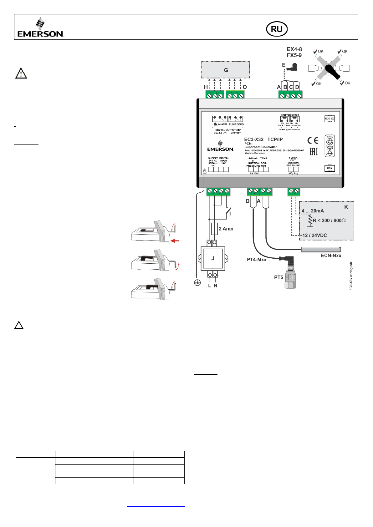
Руководство по эксплуатации
• ECD-002 можно устанавливать в панель с вырезом
легко ломаются.
Источник
Рабочее состояние
Цифровой вход (I)
Компрессор запускается
Замкнут /24 В (Старт)
Компрессор останавливается
Разомкнут /0 В (Стоп)
Требуется (компр. д.б. ВКЛ)
Замкнут /24 В (Старт)
Не требуется
Разомкнут /0 В (Стоп)
!
Контроллер перегрева EC3-X32 с сетевой
Общая информация:
EC3-X32 это универсальный контроллер перегрева с сетевой картой TCP/IP для
работы с Электрическими Регулирующими Клапанами Alco с шаговым
двигателем серии EX4...EX8 и FX5…FX9.
Инструкция по безопасности:
• Внимательно прочитайте инструкцию по эксплуатации. Ее
невыполнение может привести к поломке прибора, выходу из строя
системы или травме персонала.
• В соответствии с EN 13313 данный прибор предназначен для
использования персоналом, имеющим необходимые знания и навыки.
• Не превышайте указанные предельные значения давления,
температуры, напряжения и силы тока.
• Перед установкой отключите электропитание от системы.
• Не включайте систему до завершения подключения всех кабелей.
• Электрические подключения необходимо производить в соответствии с
законодательством Вашей страны.
Внимание: Контроллер EC3-X
32 содержит свинцово-кислотный гелевый
аккумулятор. Этот аккумулятор НЕ должен утилизироваться с остальными
промышленными отходами. Пользователь несет ответственность за передачу
его на специальные пункты приема для безопасной переработки батарей
(согласно директиве 2012/19/
EU). Для получения дополнительной информации
обратитесь в местный центр по экологической утилизации отходов.
Монтаж:
EC3-X32 предназначен для монтажа на стандартную DIN-рейку. Положение
при установке: на вертикальной стене, разъем шагового двигателя должен быть
только сверху.
Mounting of ECD-002
• ECD-002 можно устанавливать в любое время, даже во время работы
системы.
картой TCP/IP
Электрические подключения:
71x29 мм
• Вставьте дисплей в вырез панели. (1)
• Убедитесь, что монтажные выступы находятся на
одном уровне с внешней поверхностью корпуса
дисплея
• Вставьте шестигранный ключ в отверстия на
передней панели и вращайте по часовой стрелке.
Монтажные выступы будут поворачиваться и
постепенно приблизятся к панели (2)
• Вращайте ключ пока монтажный выступ не
коснется панели. Затем переместите второй
монтажный выступ в такое же положение (3)
• Очень осторожно уплотняйте обе стороны пока
дисплей не будет зафиксирован. Не прилагайте
большие усилия, так как монтажные выступы
Электрические соединения:
• Обращайтесь к схеме подключения при выполнении эл. соединений.
• Не подавайте напряжение на контроллер до завершения подключений.
• Выполните заземление металлического корпуса клеммой 6,3 мм.
• Располагайте соединительные провода контроллера и датчиков отдельно от
силовых кабелей. Миним.допустимое расстояние – 30 мм.
• Для обеспечения питания 24 В перем. тока используйте трансформаторы II
класса. Не заземляйте питающие кабели 24 В перем. тока. Для контроллера
EC3 и контроллеров стороннего производства рекомендуется использовать
индивидуальные трансформаторы, чтобы исключить возможное взаимное
влияние или проблемы с заземлением питающих кабелей.Подключение
любых входов контроллера EC3 к силовому электропитанию приведет к
выходу контроллера из строя.
• Использование цифрового выхода является необходимым в случае
пропадания питающего напряжения, если отсутствует сетевой интерфейс
или дисплей
• Если цифровой выход не используется, пользователь должен обеспечить
необходимую защиту системы в случае пропадания питающего напряжения
• Чтобы обеспечить защиту системы от пропадания питающего напряжения,
рекомендуется ежегодно менять встроенный аккумулятор
Состояние цифрового входа зависит от работы компрессора/термостата
A: Белый провод B: Черный C: Синий D: Коричневый
E: Кабель с разъемом EXV-Mxx для подключения EX4…EX8 и FX5…FX9
G: Выносная панель управления, системный контроллер
H: Аварийное реле, сухой контакт. Катушка реле обесточена при аварии или
отсутствии питания
I: Цифровой вход (0 В/разомкнут = Стоп; 24 В/замкнут = Старт)
J: Трансформатор класса II, вторичная обмотка 24 В перем. тока / 25 ВА
K: Контроллер стороннего производства (может использовать сигнал
аналогового выхода от EC3)
O: Выходное реле откачки, сухой контакт. При нормальной работе
Подготовка к пуску:
• Провести вакуумирование всего хладагентного контура.
• Внимание: ЭРВ EMERSON EX4...EX8 и FX5…FX
9 поставляются в
наполовину открытом положении. Не заправляйте систему до закрытия
вентиля.
• Подайте питающее напряжение 24 В на EC3, если на цифровом входе 0 В
(разомкнут). Вентиль будет закрываться.
• После закрытия вентиля начинайте заправку системы хладагентом.
• Запустите систему и проверьте перегрев и рабочие параметры.
Компрессор
Термостат
Emerson Climate Technologies GmbH www.emersonclimate.eu
Am Borsigturm 31 I 13507 Berlin I Germany Date: 03.04.2017 EC3-X32_OI_ML_R13_865008.docx
Page 27

Руководство по эксплуатации
Завод.
настр.
Рабоч.
настр.
H5
Пароль
1
199
12 u0
Хладагент
0
15 1
0 = R22 1 = R134a 2 = R507 3 = R404A
12 = R449A 13 = R450A 14 = R513A 15 = R1234ze
uP
Тип используемого датчика давления
0 3 0
0 = PT5-07x (для R22 / R134a / R507 / R404A / R407A / R407C /
3 = PT5-50x (для R744)
ut
Тип используемого клапана
1
12 5
1 = EX4 2 = EX5 3 = EX6 4 = EX7
9 = FX7 10 = FX7.5 11 = FX8 12 = FX9
uu
Открытие клапана при пуске (%)
0
100
50
u9
Время открытия при пуске (сек)
0
120 5
uL
Авария по низкому перегреву
0 2 1
0 = отключена (для затопленных испарителей)
Срабатывание при 0,5K (если длится 1мин); немедл.возврат к 3K
u5
Уставка перегрева (K)
Если uL отключен
0.5
30
6
u2
Функция MOP
0 1 1
0 = отключена 1 = включена
u3
Уставка MOP (°C) темп. насыщения
* * **
**) Завод. уставка в соответствие с выбранным хладагентом (u0):
хладагента.
┌┘5
Преобразование единиц
0 1 0
0 = °C, K, bar 1 = °F, R, psig
(Значение Psig делится на 10. Пример: на дисплее 12.5 - 125 psig)
┌┘1
Отображаемый параметр
0 4 0
0 = Измеренный перегрев (K)1 = Измерен. давление кипения (бар)
4 = Температура кипения (°C), вычисленная по давлению
u4
Режим управления перегревом
2 = промежуточный контроль
0 2 0
uH
Авария по высокому перегреву
0 = отключена, 1 = автовозврат включ
1
uA
Уставка аварии по высокому перегреву
16
40
30
ud
Задержка аварии по выс.перегреву, мин
1
15 3
P2
Темп.срабат.защиты по замерзанию, °C
-40
40 0
P3
Снятие защиты по замерзанию, °C
-37
43 3
P4
Авария по защите от замерзания
ручной возврат вкл.)
0 2 0
P5
Задержка сраб.защиты от замерз.-я, сек
5
199
30
P6
Откачка
(0 = отключ., 1 = автовозврат включен)
0 1 0
P7
Давление сраб.реле откачки, бар (избыт.)
-0,5
18
0.5
P8
Задержка откачки, сек
0
199
30
P9
Авария по низкому давлению
2 = ручной возврат включен)
0 2 0
PA
Сраб.аварии по низк.давл., бар (избыт.)
-0,8
17,7 0
Pb
Задержка аварии по низк.давл., сек
5
199 5
Pd
Снятие аварии по низк.давл., бар (избыт.)
-0,5
18
0.3
Мигает: вентиль
Мигает: клапан открывается
Вкл: требуется
Вкл: авария
Настройка/сохранение
параметров
Prg & Sel (5 секунд)
След.параметр/
След.параметр/
Prg & Sel (5 секунд)
Контроллер перегрева EC3-X32 с сетевой
ECD-002 дисплей/клавиатура: (функции светодиодов и
кнопок)
закрывается
Вкл: вентиль закрыт
полностью
Горит:клапан открыт
Выкл: не
требуется
Мигает: откачка
Выкл: нет аварии
Ручной сброс для
мигающих кодов
аварии
Ручной сброс для
мигающих кодов
аварии
Процедура изменения параметров с помощью дисплея
ECD-002:
• Внимание: Некоторые из функций/параметров (ручное управление и
конфигурация TCP/IP) не могут изменяться через дисплей ECD-002 в
отличие от настройки с ПК через TCP/IP.
• Предупреждение:
Предупреждение: Все аварии блокируются при ручном управлении.
Мы не рекомендуем оставлять систему без присмотра при работе в
ручном режиме.
• Доступ к параметрам осуществляется через 4-кнопочную клавиатуру.
Возможность изменения параметров защищена цифровым паролем. Пароль
по умолчанию - “12”.
• Для выбора конфигурации параметра:Нажмите и удерживайте кнопку PRG
более 5 секунд, на дисплее будет мигать “0”
• Нажмите или пока на дисплее не появится “12” (пароль), Нажмите SEL
для подтверждения пароля
• Нажмите или для выбора кода параметра, который надо изменить;
Нажмите SEL для вывода значения выбранного параметра;
• Нажмите или , чтобы увеличить или уменьшить значение; Нажмите
SEL, чтобы подтвердить новое значение и отобразить его код;
• Повторите данную процедуру сначала "нажмите или для показа..."
• Чтобы выйти и сохранить новые настройки: Нажмите PRG, чтобы
подтвердить новые значения и выйти из режима изменения параметров.
• Чтобы выйти без изменения параметров: Не нажимайте никакие кнопки
хотя бы 60 секунд (время выхода).
Специальные функции:
• Специальные функции можно активировать:
• Нажмите кнопки и вместе на более чем 5 секунд, на дисплее будет
мигать “0”.
• Нажмите или пока не появится пароль (по умолчанию = “12”).
• Если пароль был изменен, выберите новый пароль.
• Нажмите SEL для подтверждения пароля
• На дисплее будет “0” и режим Специальных функций активирован.
• Нажмите или для выбора функции. Количество специальных функций
- в развитии и зависит от контроллера. См. список ниже.
0 Возврат контроллера к заводским настройкам (это возможно только
когда цифровой вход 0В, т.е. разомкнут)
1: Отображение текущего TCP/IP-адреса
2: Временная установка TCP/IP-адреса в 192.168.1.101, если EC3-X32 имеет
другой адрес
• Нажмите SEL для активации этой функции без выхода из режима
специальных функций.
• Нажмите PRG для активации этой функции и выхода из режима специальных
функций.
картой TCP/IP
значение (выше)
значение (ниже)
Основные параметры:
(проверить и изменить, если требуется)
Код Описание параметра и варианты Мин Макс
4 = R407C 5 = R410A 6 = R124
7 = R744 (субкритическое применение)
8 = R407A; 9 = R407F 10 = R32* 11 = R448A
R407F / R124 / R448 A /R449A / R450A / R513A /
R1234ze)
1 = PT5-18x (для R410A / R 3 2)
2 = PT5-30x (для R410A / R744 / R32)
5 = EX8 6 = FX5 7 = FX6 8 = FX6.5
1 = автовозврат включен 2 = ручной возврат включен
Если uL включен (авто или ручной)
+13°C - R22 +15°C - R134a +7°C - R507
+7°C - R404A +15°C - R407C +15°C - R410A
+50°C - R124 -5°C - R744 +10°C - R407A
+10°C - R407F +10°C - R32 +12°C - R448A
+12°C - R449A +19°C - R450A +13°C - R513A
+24°C - R1234ze
*) Мин. и Макс. значения настроек зависят от выбран. типа
2 = Открытие клапана (%)3 = Измерен. темп. трубы на выходе (°C)
0 = стандартный, 1 = медленный
(0 = отключ., 1 = автовозврат включ., 2 =
(0 = отключена, 1 = автовозврат включ.,
3
30
6
Emerson Climate Technologies GmbH www.emersonclimate.eu
Am Borsigturm 31 I 13507 Berlin I Germany Date: 03.04.2017 EC3-X32_OI_ML_R13_865008.docx
Page 28

Руководство по эксплуатации
с
Завод.
Рабоч.
L2
Логика выходов
0 3 1
0: авария = норма, откачка = норма
3: авария = обратн., откачка = обратн
b1
Обработка ошибок аккумулятора, если
аккумулятор неисправен, см. ниже:
0 3 2
Знач.
Отображ.
аварии
Авар. реле
Вентиль
Возм. возврата после
зарядки/замены
0 -
-
Продол.работать
-
1 Ab
-
Продол.работать
-
2 Ab
Срабатыв.
Полное закрытие
Авто
3 Ab
(мигает)
Срабатыв.
Полное закрытие
Ручной
от повреждения, вызванного пропаданием электропитания.
uF
Диапазон регулирования клапана %
5
100
100
FX9 ≤ 9. секунды
Состояние
Цифрового входа
Состояние
аварии
24В (Вкл)
НЕТ
активировано
Отключено, когда давление падает
ниже P7 и по истечении времени P8
0В или 24В
ДА
Отключено
!
Sec.
uu
u9
%
EC3-X3 BA.cdr
Контроллер перегрева EC3-X32 с сетевой
Код Описание параметра и варианты Мин
1: авария = обратн., откачка = норма
2: авария = норма, откачка = обратн.
При установке b1 в значение 0 или 1, пользователь обязан
обеспечить должные меры безопасности, чтобы защитить систему
Мак
*)Внимание R32: В Европе хладагент R32 считается слабогорючим.
Контроллеры EC3-X32 в соответствии с Евростандартами и директивами
разработаны для негорючих хладагентов. Использование EC3-X32 с R32
возможно в системах/регионах, где не требуется соблюдение дополнительных
стандартов безопасности для горючих хладагентов.
После завершения программирования EC3-X32 может работать без
подключения к ПК и без дисплея ECD-002.
Пусковой алгоритм вентиля (параметры uu и u9):
картой TCP/IP
настр.
настр.
• EC3-X32 имеет сетевой интерфейс TCP/IP Ethernet, позволяющий
подключать контроллер непосредственно к сети или к ПК через стандартный
порт Ethernet. Контроллер EC3-X32 имеет встроенные веб-страницы,
позволяющие пользователю видеть списки параметров, используя реальные
текстовые данные.
• Для просмотра Веб-страниц на ПК требуется стандартный Веб-браузер,
например Internet Explorer® или Mozilla Firefox, а также программа JRE Java
Runtime Environment (Ява). Программу JRE можно бесплатно скачать с вебсайта www.java.com.
• Откройте веб-браузер на ПК и, если EC3-X32 подключен к ПК напрямую с
помощью кросс-кабеля, введите в адресной строке TCP/IP-адрес
контроллера по умолчанию (192.168.1.101), или динамический адрес,
назначенный DHCP-сервером сети/маршрутизатора. Обращайтесь к
инструкции по работе с TCP/IP-контроллерами, если требуется специальный
порт.
• Имеется возможность определить динамический TCP/IP-адрес, назначенный
DHCP-сервером маршрутизатора или сети - обращайтесь к инструкции по
работе с TCP/IP-контроллерами.
• Через несколько мгновений должна появиться страница просмотра
параметров. Если браузер не открыл стандартную страницу или показывает
рабочий процесс открытия, пользователь должен проверить настройки в
меню “Сервис” Интернет-браузера. Обращайтесь к инструкции по работе с
TCP/IP-контроллерами.
EX4/5/6 ≤ 1.5 секунды
EX7 ≤ 3.2 секунды
EX8 ≤ 7.2 секунды
FX5-8 ≤ 7.3 секунды
Функция откачки (если P6=1 и L2=1):
Реле откачки
0В (Выкл) НЕТ
Возможности подключения EC3-X32 к сети или ПК
• На веб-сайте www.emersonclimate.eu имеется инструкция по работе с TCP/IP-
контроллерами, предоставляющая подробную информацию по
установлению связи в сетях TCP/IP Ethernet. Обращайтесь к этой
инструкции, если вам нужна информация, не вошедшая в данный документ.
• Подключите EC3-X32, используя кабель ECC-Nxx или стандартный сетевой
кабель CAT5 с разъемами RJ45, к сети или маршрутизатору, который
позволяет контроллеру получать динамический TCP/IP-адрес или
• Подключите EC3-X32 непосредственно к порту Ethernet компьютера,
используя кросс-кабель. В этом случае необходимо вручную изменить
TCP/IP-адрес этого ПК, чтобы быть совместимым с адресом контроллера,
установленным по умолчанию. За дополнительной информацией
обращайтесь к инструкции по работе с TCP/IP-контроллерами.
Настройка и отображение данных: Веб-страницы
(рекомендованный метод)
• Важно: Убедитесь, что цифровой вход разомкнут (0 В). Включите
электропитание контроллера.
• Четыре параметра, т.е. тип хладагента (u0), тип датчика давления (uP), тип
вентиля (ut) и режим управления можно настраивать только, если цифровой
вход разомкнут (0 V) при включенном электропитании (24 В). Эта функция
дает дополнительную защиту, чтобы предотвратить случайное повреждение
компрессоров и других компонентов системы. Все остальные параметры
можно менять в любое время.
• Веб-страницы просмотра параметров и аварийных сообщений доступны
только для просмотра и поэтому не требуют пароля. Имя пользователя и
пароль потребуются при первом входе на любую другую веб-страницу.
Заводские настройки по умолчанию следующие:
• Имя пользователя: “EmersonID”, Пароль: “12”
• Настройки по умолчанию можно изменить на странице Конфигурация
дисплея.
• Выберите закладку в верхней части страницы просмотра и нажмите левую
кнопку мышки, чтобы открыть соответствующую веб-страницу.
• Параметры будут отображаться в виде реальных текстовых данных вместе с
программным кодом, который задан в списке параметров ниже.
• После изменения параметров, полный список настроек можно сохранить в
памяти компьютера и использовать позднее для загрузки в другой
контроллер. Это позволит значительно сэкономить время, если используется
множество контроллеров, и по прошествии определенного времени у вас
будет создана библиотека, содержащая списки параметров для оборудования
для разного применения.
• Также возможен вывод на экран текущих графических данных с
контроллера. Значение перегрева, давление и температура кипения,
температура на выходе из теплообменника доступны в виде
разворачивающихся графиков за 15 минут. Обращайтесь к инструкции по
работе с TCP/IP-контроллерами за полным описанием возможностей
контроллеров TCP/IP серии.
Emerson Climate Technologies GmbH www.emersonclimate.eu
Am Borsigturm 31 I 13507 Berlin I Germany Date: 03.04.2017 EC3-X32_OI_ML_R13_865008.docx
Page 29
Треб. ручной
снятия аварии
Ошибка
датч.давления
Ошибка
датч.температ.
Проверьте подключение и замерьте сопротивление
датчика
Ошибка эл. соедин.я EXV
Проверьте подключение и замерьте сопротивление
обмотки
Ab
b1: 1
-
Регулирует
Аккумулятор может не иметь достаточного заряда для
заменить. (Комплект для замены: 807 790).
-
Ab
Откачка не может
быть выполнена
Выявите причину, которая не позволяет давлению
всасывания падать ниже желаемой уставки
AL
uL: 1
Сигнализ.
Полн.закрыт
Нет
AL
мигает
AH
Высокий перегрев
uH: 1
Сигнализ.
Полн.закрыт
Проверьте систему
Нет
AP
P9: 1
Сигнализ.
Полн.закрыт
Нет
AP мигает
P9: 2
Сигнализ.
Полн.закрыт
Да
Ошибка
пределом диапазона
Проверьте кабель и соединение между EC3-X3… и
ECD-002
Рабочий перегрев на несколько градусов выше или
Неправильный сигнал от датчика
1- Проверьте датчики
силовыми кабелями
Рабочий перегрев слишком мал, т.е. у компрессора
влажный ход
1-Неправильное подключение ЭРВ
2-Неисправные датчики
1- Проверьте подключение
2- Проверьте датчики
Вентиль не закрывается полносттью
1-Цифровой вход ВКЛ (24 В)
2-Неправ-я настройка параметра ut.
1-Вентиль закрывается только когда цифр.вход выключен (0 В)
Нестабильный перегрев (рыскание)
Испаритель предназначен для
работы с большим перегревом
Увеличьте уставку перегрева
Вентиль открывается, когда EC3 дает команду на
закрытие и наоборот
Неправильное соединение между
EC3-X3.. и вентилем
Обеспечьте правильное соединение
EX8 не может открыться при высокой разнице
давлений
Неправильная настройка параметра
ut
Проверьте параметр ut. (Больший вентиль требует большего
усилия и большего тока)
Уставка перегрева изменяется после нескольких
замкнутым цифровым входом 24 В
Вентиль с шаговым двигателем
Не подавайте 24 В на цифровой вход постоянно. Если
вход раз в неделю на 5 секунд.
Обработка Ошибок/Аварий:
Код
аварии
Описание
Связан.
параметр
Руководство по эксплуатации
Контроллер перегрева EC3-X32 с сетевой
картой TCP/IP
Авар.
реле
Вентиль
Что делать?
возврат после
E0
E1
AΠ
Ab мигает
AE мигает
AF
AF мигает
Er
---
Ошибка
аккумулятора
Защита от
замерзания
Низкий перегрев
(<0,5K)
Низкое давление
отображения
данных – за
Нет данных - - -
- Сигнализ. Полн.закрыт Проверьте подключение и замерьте сигнал 4 ... 20 мА Нет
- Сигнализ. Полн.закрыт
- Сигнализ. -
b1: 2 Сигнализ. Полн.закрыт -
закрытия вентиля при пропадании основного эл.питания.
Это может временами происходить с новыми
Нет
Нет
контроллерами или при длительном их хранении, но
b1: 3 Сигнализ. Полн.закрыт Да
P6: 1 Сигнализ. P4: 1 Сигнализ. Полн.закрыт
P4: 2 Сигнализ. Полн.закрыт Да
uL: 2 Сигнализ. Полн.закрыт Да
должно исчезнуть после зарядки аккумулятора. Если Ab
остается активным и после зарядки, аккумулятор следует
Проверить систему на предмет снижения давления,
например, недостаточной нагрузки на испаритель
Проверьте подключение и работу вентиля
Да
Нет
Проверить систему на предмет снижения давления,
например, утечки хладагента
Данные, выводимые на дисплей, находятся за пределами
- - -
диапазона дисплея. Проверьте датчик температуры и
давления.
Нет
Нет
Примечание: При возникновении нескольких аварий, на дисплее будет видна авария наивысшего приоритета пока не будет снята, затем будет показана следующая по
приоритету авария пока все аварии не будут сняты. Только после этого на дисплее будут снова видны параметры.
Проверка параметров работы системы с помощью местного дисплея ECD-002:
Данные, которые будет постоянно показывать дисплей, могут быть выбраны пользователем (параметр
функция отключается в случае аварии. Дисплей будет показывать в течение секунды цифровой код данных (см. параметр
минут дисплей вернется к значению, выбранному параметром
┌┘1.
┌┘1). Имеется возможность временно показывать эти значения.
┌┘1), а затем выбранное значение. Через 5
Сервис / Поиск неисправностей:
Симптом Причина Действие
ниже уставки
давления или температуры
2- Убедитесь, что используется датчик температуры ECN-N60
3- Для оптимальной точности используйте:
PT5-07x (для R22 / R134a / R507 / R404A / R407A / R407C /
R407F / R124 / R448A /R449A / R450A / R513A /
R1234ze)
PT5-18x (
PT5-30x (
PT5-50x (
для R410A/ R32)
для r R410A / R744 / R32)
для R744)
4- Убедитесь, что кабели датчиков не проходят рядом с
2-Проверьте настройку параметра ut
месяцев непрерывной работы или с постоянно
требует синхронизации
компрессор никогда не останавливается, размыкайте цифровой
Emerson Climate Technologies GmbH www.emersonclimate.eu
Am Borsigturm 31 I 13507 Berlin I Germany Date: 03.04.2017 EC3-X32_OI_ML_R13_865008.docx
Page 30
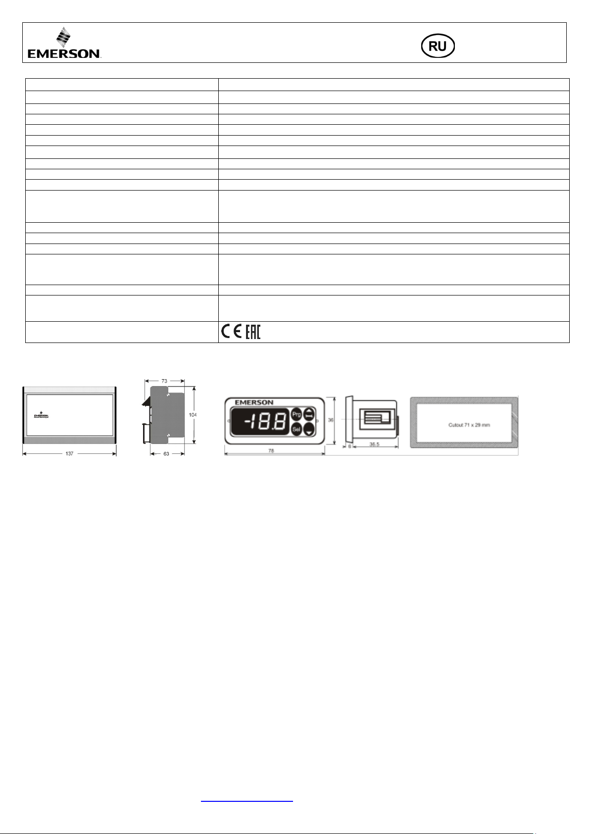
Электропитание
24 В перем. тока ±10%; 50/60 Гц; 1 А
Разъемы
Съемные винтовые разъемы для провода сечением 0,14…1,5 мм2
Заземление
Клемма заземления 6,3 мм
Класс защиты
IP20
COM, TCP/IP –соединение
Разъем RJ45 Ethernet
Соединение для ECD-002
ECC-Nxx или кабель CAT5 с разъемами RJ45
Цифровые Входы
0/24В перем/пост. тока /для пуска/остановки
NTC вход
Датчик температуры EMERSON ECN-N60
Аналог. Вход 4-20 мА
EMERSON PT5
Аналог. Выход 4-20 мА
Отклонение от входного сигнала
Выходное аврийное реле
SPDT-контакт 24 В перем./пост. тока, индуктивная нагрузка 2 А
(Если L2 = 1) активир.:
При нормальной работе (нет аварии)
отключено:
При аварии или выключенном питании
Выходное реле откачки
отключено:
Выход шагового двигателя для EX4…EX8, FX5…FX9
Макс. ток 0,8 А при номинальном напряжении 24 В постоянного тока
0…+60°C
> 35°C срок работы аккумулятора < 2 лет
Контроллер перегрева EC3-X32 с сетевой
Руководство по эксплуатации
картой TCP/IP
Технические данные:
Энергопотребление 25 ВА макс., включая EX4…EX8
(Если L2 = 1) активир.:
Диапазон окружающей температуры
Маркировка
Размеры [мм]:
EC3-X32 ECD-002
Для соединения с контроллером стороннего производства с питанием 12/24 В пост. тока и
надлежащей нагрузкой
±8% макс.
SPDT-контакт 24 В перем./пост. тока, индуктивная нагрузка 2 А
При нормальной работе
При других условиях
+1…+25°C (больший срок работы аккумулятора)
,
Emerson Climate Technologies GmbH www.emersonclimate.eu
Am Borsigturm 31 I 13507 Berlin I Germany Date: 03.04.2017 EC3-X32_OI_ML_R13_865008.docx
 Loading...