

Page 1

Operating instruction
EC3-D7x Digital Superheat Controller
EC3-D72 with TCP/IP communication capability
Emerson Climate Technologies GmbH www.emersonclimate.eu
Am Borsigturm 31 I 13507 Berlin I Germany Date: 18.07.2017 EC3-D7x_OI_ML_R06_865019.docx
General information:
EC3-D72 is the superheat controller with TCP/IP connection for stepper motor
driven Electrical Control Valves EX4-6 from EMERSON and is optimiz ed to oper ate
with the Copeland Digital Scroll series utilizing a 0-10V input from a third-party
controller. The controller synchronizes the PWM digital compressor solenoid valve
with the superheat controlled by the electrical control valve; EX series.
The EC3-D73 has the same functionality but can only be set-up via the ECD-002
display. It has no external communication functi onality.
Safety instruc tions:
• Read operatin g ins tructi ons th orou ghly. Failur e to com ply c an res ult in device
failure, system damage or personal injury.
• According to EN 13313 it is intended for use by persons having the
appropriate knowledge and skill.
• Do not exceed the specified maximum ratings for pressure, temperature,
voltage and current.
• Before in stallation or service disconnect all voltages from system and device.
• Do not operate system before all cable connections are completed.
• Entire electr i c a l c on n e c t ions have to comply with local regulations.
Note: The EC3 -D7x series contains a VRLA battery = valve regulated rechargeable
lead-acid battery. The batte ry m ust NOT be dis posed of w ith othe r comme rcia l was te.
Instead, it is the use r ’s r es ponsi bility t o pass it to a desig na te d col le ctio n po int f or the
safe recycling of batteries (harmonized directive 2012/19/EU). For further
information contact your local environmental recycling center.
Mounting position:
The EC3-D7x is designed to be mounted onto a standard DIN rail. Mounting
position: on vertic al walls, with stepper motor conn ector on top side only.
Mounting of ECD-002:
• ECD-002 can be installed at any time also during operation.
• ECD-002 can be mounted in panels with
71x29 mm cutout.
• Push controller into panel cut-out.(1)
• Make sure that mounting lugs are flush with
outside of controller h ousing
• Insert Allen key into front panel holes and turn
clockwise. Mounting lugs will turn and gradually
move towards panel (2)
•
Turn Allen key until mounting lug barely touches
panel. Then move other mounting lug to the same
position (3)
• Tighten both sides very carefully until keypad is
secured. Do not over tighten as mounting lugs
will break easily.
Electrical Installation:
• Refer to the electrical wiring diagram for electrical connections.
• Do not apply voltage to the controller before completion of wiring.
• Ground the metal housing with a 6.3 mm spade connector.
• Keep controller and sensor wiring well separated from mains wiring. Minimum
recommended distance 30 mm.
• Use a class II category transformer for 24 VAC power supply. Do not ground the
24 VAC lines. We recommend using individual transformers for EC3 controller(s)
and for 3
rd
party controllers t o avoid poss ible in terference or gr oun ding p roblems
in the pow er suppl y. Connecting any EC3 inputs to mains voltage will permanently
damage the EC3.
• The use of the relay is essential to protect the system in case of power failure if the
communications interface or the ECD-002 are not utilized.
• If the output relay is not utilized, the user must ensure appropriate safety pre-
cautions are in place to protect the system against damage caused by a power
failure.
• In order to provide system protection in the event of power loss, it is recommended
to change the battery annually.
Digital input status is dependent to operation of compressor/ 0-10V input
System
Operating
condition
Digital Inputs
0-10V input from third party
controller
C1 &
C2 in stop mode
“Cooling demand” open (0 V)
“Comp 2 Running” open (0 V)
EXV remains cl o sed irrespec tive
of voltage input value
C1 in run &
C2 in stop mode
“Cooling demand” closed (24
V)
“Comp 2 Running” open (0
V)
EXV active
Input = 0V: dig. valve capacity =
10% default ca pa city.
If dig. comp. is in by-pass,
EXV will:
- close if capacity is <70%
- be inhibited if capacity is
>70%
C1 &
C2 in run mode
“Cooling demand” closed (24 V)
“Comp 2 Running” closed (24
V)
EXV active
EXV always modulates
even when
the dig. compr. is in by-pass mode.
C1 in stop &
C2 starts run
mode
“Cooling demand” open (0 V)
“Comp
2 Running” closed (24 V)
EXV remains clo sed irrespec t ive
of voltage input value
Note 1: C1 = Compressor 1, C2 = Compressor 2
Note 2: Digital comp. s ho uld always be regarded as base load compressor 1.
Wiring:
A: White wire
B: Black wire
C: Blue wire
D: Brown wire
E: M12 Plug cable assembly EXV-Mxx for connection to EX4-6
F: 24 V Triac output to PWM Digital Scroll valve
G: Remote control panel, system controll er.
H: Alarm relay, dry contact. Relay coil is not energized at alarm or power off.
I: Digital input “Cooling demand” (0 V/open = Stop; 24 V/closed = Start)
J: Transformer Class II, 24 VAC secondary / 25 VA
K: Third party controller (can use the analog output signal from EC3)
L: Pump down relay, dry contact. Relay is energized during normal operation
M: Digital input 2: “Comp 2 running”
(0 V/ open = Comp 2 stop; 24 V /closed = Comp. 2 running)
N: Discharge Temp. Sensor C opeland® NTC
O: 0-10 V Digital Scroll capacity demand signal from system controller
P: ECN-N60 Temperature sens o r
!
Page 2

Operating instruction
EC3-D7x Digital Superheat Controller
EC3-D72 with TCP/IP communication capability
Emerson Climate Technologies GmbH www.emersonclimate.eu
Am Borsigturm 31 I 13507 Berlin I Germany Date: 18.07.2017 EC3-D7x_OI_ML_R06_865019.docx
Preparation for Start-up:
• Vacuum the entire refrigeration system.
• Note: EMERSON Electrical Contr ol Valves EX4-6 a re delivered at half open
position. Do not char ge syst em before closure of valve.
• Apply supply voltage 24 V to EC3 while the digital input is 0 V (open). The valve
will be driven to close position.
• After closure of valve, start to charge the system with refrigerant.
• Start the system and check the superheat and operating conditions.
ECD-002 display /keypad unit: (LEDs and button functions)
Procedure for parameter modification using ECD-002:
• Note: Some of the functions/parameters (manual control and TCP/IP
configuration) cannot be modified when using ECD-002 comparing to a set-up by
PC via TCP/IP.
• Warning:
All alarms are disabled during manual control. We do not recommend
unattended operation of system during manual control.
• The parameters can be accessed via the 4-button keypad. The configuration
parameters are protected by a numerical password. The default password is “12”.
To select the parameter configuration:
• Press the PRG button for more than 5 seconds, a flashing “0” is displayed
• Press or until “12” is displayed (password)
• Press SEL to confirm password
• Press or to show th e code of the parameter that must be changed;
• Press SEL to displa y the selected par ameter value;
• Press or to increa se or decrease the value;
• Press SEL to temporarily confirm the new value and display its code;
• Repeat the procedure from the beginning "press or to show..."
• To exit and save the new settings: Press PRG to confirm the new values and exit
the parameters modification procedure.
• To exit without modifying any parameters: Do not press any button for at least
60 seconds (TIME OUT).
Special Functions :
The Special F un c t ions can be activated by:
• Press and together for more th an 5 seconds, a flashing “0” is displayed.
• Press or until the passw ord is displayed (default = “12”).
If password was changed, select the new password.
• Press SEL to confirm password
A “0” is displayed and the Special Function mode is activated.
• Press or to select the function. The number of special functions is dynamic
and controller dependent. See list below.
0: Reset controller to factory settings (this action is possible only when
digital input is 0 V i.e. open).
1: Displays the current TCP/IP address.
2: Assign temporary 192.168.1.101 as TCP/IP address if EC3-D72x has
different address.
• Press SEL to activate the func tion without leaving the speci al function mode.
• Press PRG to activate the function and leave the special function mo de.
Main parameters:
(must be checked and modified if necessary)
Code Parameter description and choices Min Max
Factory
setting
Field
setting
H5
Password
1
199
12 u0
System refrigerant
0
15 1
0 = R22 1 = R134a 2 = R507 3 = R404A 4 = R407C
5 = R410A 6 = R124 7 = R744 (subcritical applicatio n)
8 = R407A 9 = R407F 10 = R32* 11 = R448 A
12 = R449A 13 = R450A 14 = R513A 15 = R1234ze
uP
Installed pressure sensor type
0
2 0
0 = PT5-07x (for R22 / R134a / R507 / R404A / R407A / R407C /
R407F / R124 / R448 A /R449A / R450A / R513A /
R1234ze)
1 = PT5-18x (for R410A/ R32)
2 = PT5-30x (for R410A / R744 / R32)
ut
Installed valve type
1 3 2
1 = EX4 2 = EX5 3 = EX6
uu
Start valve opening (%)
10
100
50
u9
Start opening duration (second)
1
30 5
uL
Low superheat alarm function
0 2 1
0 = disable (for flooded evaporator)
1 = enable aut o reset 2 = enable manual reset
Cut-out at 0.5K (if it maintains 1 min.); Cut-in immediately at 3K
u5
Superheat set-point (K)
If uL enabled (auto or manual)
If uL disabled
3
0.5
30
30
6
6
u2
MOP function
0 1 1
0 = disable 1 = enable
u3
MOP set-point (°C) saturation temper atur e
* * **
**) Factory setting is according to selected refrigerant (u0):
+13°C - R22 +15°C - R134a +7°C - R507
+7°C - R404A +15°C - R407C +15°C - R410A
+50°C - R124 -5°C - R744 +10°C - R407A
+10°C - R407F +10°C - R32 +12°C - R448A
+12°C - R449A +19°C - R450A +13°C - R513A
+24°C - R1234ze
*) Min. and Max . setting values are dependent to selected type o f
refrigerant
┌┘
5
Units conversion
0 1 0
0 = °C, K, bar 1 = °F, R, psig
(Psig values are divided by 10. Example: Display 12.5 is 125 psig)
┌┘
1
Value to show
0 5 0
0 = Measured superheat (K) 1 = Measured evaporating pressure, (bar);
2 = Valve opening (%) 3 = Measured coil-out temperatur e (°C)
4 = Calculated evaporating temperature (°C) from the pressure
5 = Compressor capacity in %
u4
Superheat control mode
0 1 0
0 = Standard, 1 = Slow,
uH
High superheat alarm function
0 = disable, 1 = enable auto reset
1
uA
High superheat alarm setpoint
16
40
30
ud
High superheat alarm delay, min.
1
15 3
P2
Freeze prot ection cut-out, °C
-40
40 0
P3
Freeze prot ection cut-in, °C
-37
43 3
P4
Freeze protection alarm function
0 = disable, 1 = enable auto-reset,
2 = enable manual reset)
0 2 0
P5
Freeze protection alarm delay, sec.
5
199
30
P6
Pump-down function
(0 = disable, 1 = enable auto-reset)
0 1 0
P7
Pump-down cut-out, barg
-0,5
18
0.5 P8
Pump-down time delay, sec.
0
199
30
P9
Low pressure alarm function
(0 = disable, 1 = en able auto-reset,
2 = enable manu al reset)
0 2 0
PA
Low pressure alarm cut-out, barg
-0,8
17,7 0
Pb
Low pressure a larm delay, sec .
5
199 5
Pd
Low pressure alarm cut-in, barg
-0,5
18
0.3 L2
Output logic
0 3 1
0: Alarm = normal, pump down. = normal
1: Alarm = inverse, pump down. = normal
2: Alarm = normal, pump down. = inverse
3: Alarm = inverse, pump down. = in verse
Blinking: valve is closing
ON: valve is fully close
Blinking: valve is opening
ON: valve is fully open
ON: demand
OFF: no demand
Blinking: pump
down
ON: alarm
OFF: no alarm
Parameters setting/saving
Selecting/confirming
Next param eter/
value (higher)
Next param eter/
value (lower)
Prg&Sel (5 sec)
Manual reset f o r
blinking alarm codes
Page 3

Operating instruction
EC3-D7x Digital Superheat Controller
EC3-D72 with TCP/IP communication capability
Emerson Climate Technologies GmbH www.emersonclimate.eu
Am Borsigturm 31 I 13507 Berlin I Germany Date: 18.07.2017 EC3-D7x_OI_ML_R06_865019.docx
Code Parameter description and choices Min Max
Factory
setting
Field
setting
b1
Battery error management, when battery is
defective, see below
0 3 2
value
Alarm
display
Alarm relay
Valve
Reset possibility after
recovery/replacement
0 - - Regulating
-
1 Ab - Regulating
-
2 Ab
Signaling
Fully close
Auto
3 Ab
(blinking)
Signaling
Fully close
Manual
When setting b1 to option 0 or 1, the user must ensure appropriate safety
precautions are in pla ce to protect the s yst em against damage caused by
a power failure.
/6
Show decimal point; 0=yes, 1 = no
0 1 0 A6
Maximum dis charge temperat ure; °C
100
140
130 A7
Discharge temp. alarm de l ay; sec.
0
199
30
F2
Minimum capacity; %
10
100
10 F3
Maximum capacity; %
10
100
100
F6
Scroll Valve, PWM cycle time; sec.
10
20
20
t3
Monitor discharge temperature sensor
0 = no, 1 = Yes
0 1 0
ru
0-10V input filtering; 0 = off, 1 = on
0 1
*) Notes for R32: R32 is classified as low flammab le refrigeran t in Europe. EC3D7x is designed under consideration of European safety standards and directives for
none flammable refrigeran ts. The u se of EC3-D7x with R32 is for systems/regions
which it does not require consideration of additional safety standards as for
flammable refrigerant.
After selecting the parameters the EC3-D7x is fully functio nal w itho ut c on ne cte d PC
or keypad/display unit ECD-002.
Control (valve) start-up behavior: (Par ameter uu and u9)
EX4/5/6 ≤ 1.5 seconds
Pump down f unction: (if P6=1 and L2=1)
Digital input status
Alarm
condition
Pump down relay
24 V (ON)
NO
Activate
0 V (OFF)
NO
Deactivat e when pressure drops below
P7 and after elapsed time P8
0 V or 24V
YES
Deactivate
Possibilities of connecting EC3-D72 to a network or PC:
• A TCP/IP Controller Readme file is available on the www.emersonclimate.eu
website to provide detailed information about TCP/IP Ethernet connectivity.
Please refer to this file if you need information beyond the contents of this
instruction sheet.
• Connect t he E C3-D72 using the optional ECC-Nxx cable assembly or a standard
CAT5 netw or k cabl e with RJ45 pl ugs asse m bly t o a ne tw or k or route r that e na bl e s
the controller to receive a dynamic TCP/IP address or
• Connect the EC3-D72 to a computer using a crossover cable plugged directly into
the Ethernet port. In this case, the TCP/IP address of the computer must be
manually modified to be compatible with the default address of the controller.
Refer to the TCP/IP Controller-Readme file for more details.
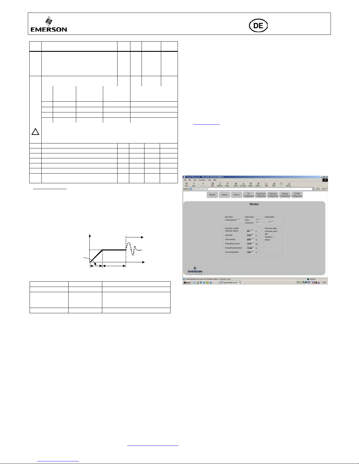
Setting and visualizing Data: WebPages
(recommended method)
• Make sure that digital input is 0V (open), turn the power supply ON.
• Four parameters i.e. refrigerant type (u0), pressure sensor type (uP), valve type (ut)
and control mode can be set only when digital input is open (0V) while the power
supply is O N (24 V). This feature is for added safety to prevent accidental damage
of compressors and other system components. All other parameters can be
modified at any time.
• The EC3-D72 has a TCP/IP Ethernet communication interface enabling the
controller t o be di rect ly conn ect ed to a net work or a P C via th e stand ard Eth ern et
port. The EC3-D72 controller has embedded WebPages to enable the user to
visualize the parameter lists using real t ex t labels.
• To view WebPages on the PC, a standard Web Br owser li ke Internet E xplorer ® or
Mozilla Firefox and JRE Java Runtime Environment is needed. JRE can be
downloaded at no charge from the www.java.com website.
• Open the Internet bro wser prog r a m o n the compute r and, if EC3-D72 is connected
directly to PC with a crossover cable enter the default TCP/IP address of the
controller (192.168.1.101) into the address line, or the dynamic address from the
DHCP server from network/Router. Refer to the TCP/IP Controller-Readme file
if a specific port is required.
• It is possible to identify the dynamic TCP/IP address assigned by DHCP of the
Router or network, refer to the TCP/IP Controller-Readme file.
• After a few moments, the default monitoring page should be displayed. If the
browser do es not open the defaul t pag e or display activ e data , the use r sho uld che ck
the Internet browser “Option” configuration. Refer to the TCP/IP Controller-
Readme file.
• The Monitoring and Alarm WebPages are read only and therefore it is not
necessary to enter a username or password. A username and password will be
requested u pon the initi al re quest to a ny of the o ther We bPage s. The factory defaul t
settings a re: Username: “EmersonID”, Password: “12”
• The default settings may be modified on the Display configuration page.
• Press the tabs at the top o f the Mon itor ing pa ge w ith a lef t clic k of the mo use butto n
to enter the respective Webp age.
• The param eters will b e visualized in real text together with the program code as
defined in the parameter list below.
• After the parameters have been modified, the complete list of settings can be saved
to the memory of the computer and used later to upload into another controller.
This can save a considerable amount of time when using multiple controllers and
over a period of time, a library can be created containing the parameter lists for
equipment for different applications.
• It is also possible to display live graphical data from the controller. Superhea t,
evaporating pressure, coil-out temperature and evaporating temperature are
available on a 15 minutes rolli ng chart. Ref er to the TCP/IP C ontroller-Readme
file for a comp lete descrip tion of the feat ures availa ble for the TCP/ IP series of
controllers.
!
Sec.
uu
u9
%
EC3-X3 BA.c dr
Page 4

Operating instruction
EC3-D7x Digital Superheat Controller
EC3-D72 with TCP/IP communication capability
Emerson Climate Technologies GmbH www.emersonclimate.eu
Am Borsigturm 31 I 13507 Berlin I Germany Date: 18.07.2017 EC3-D7x_OI_ML_R06_865019.docx
Error/Alarm handling:
Alarm
code
Description
Related
parameter
Alarm
relay
Valve What to do?
Requires manual
reset after resolvin g
alarm
E0
Pressure
transmitter error
- Signaling Fully close Check wiring connection and measure the signal 4…20 mA. No
E1
Temperature
sensor error
- Signaling Fully close Check wiring connect ion and measure the resistance of sensor. No
E3
Discharge temp.
sensor error
-
Signalling
Regulating
Check wiring connections an d measure the resistance of the
sensor. Also check the status of the I/O configuration (t3)
No
AΠ
EXV electrical
connection error
- Signaling -
Check wiring connection and measure the resistance of
winding.
No
Ab
Battery error
b1: 1
-
Regulating
Battery potentia lly does not have enough charge to close valve
in case of main power supply interruption. May occur
temporarily with new controllers or after long storage but
should disappear when battery is charged sufficiently. If Ab
remains active even when battery is charged, battery may be
defective and should be replaced. (Replacement kit: 807790).
No
Ab
b1: 2
Signaling
Fully close
No
Ab blinkin g
b1: 3 Signaling Fully close Yes
AE blinking
Pump down action
cannot
accomplished
P6: 1 Signaling -
Allocate the source, which does not let suction pressure drops
below desired set-point.
Yes
AF
Freeze prot ection
P4: 1
Signaling
Fully close
Check the system for cause of low pressure such as insufficient
load on evaporator.
No
AF blinking
P4: 2
Signaling
Fully close
Yes
AL
Low superheat
(<0,5K)
uL: 1
Signaling
Fully close
Check wiring connect ion and operation of valve.
No
AL
blinking
uL: 2 Signaling Fully close Yes
AH
High superheat
uH: 1
Signaling
Fully close
Check the system.
No
AP
Low pressure
P9: 1
Signaling
Fully close
Check the system for cause of lo w pressure such as refrigerant
loss.
No
AP blinking
P9: 2
Signaling
Fully close
Yes
dA
High discharge
temp.
A6: alarm
setpoint
Signalling
Fully close
Pumpdown
deactivated
Check the system
No
Fixed differential =
10°C
Er
Data error display
- out of range
- - -
Data send to the display is out of range. Check temperature and
pressure sensor.
No
---
No data to display - - -
Check Cable and plug connecti on between EC3-D7… and
ECD-002.
No
Note: When multiple alarms occur, the highest priority alarm is displayed until being cleared, then the next highest alarm is displayed until all alarms are cleared. Only then
will parameters be shown again.
Checking system operating conditions using local display/keypad ECD-002:
The data to be permanently shown on the display can be selected by the user (parameter ┌┘1). It is possible to temporarily display these values. However this function is
not available in an alar m co ndition. The display will show for one second the numerical identifier of the data (see ┌┘1 parameter) and then the selected data. After 5 minutes,
the display will return to the value selected by parameter ┌┘1.
Service / Troubleshooting:
Symptom Cause Action
Operating superheat is several degrees higher or lower
than set-point
Incorrect signal from pressure or
temperature sensors
1- Check the sensors.
2- Make sure EC N -N6 0 temperature sensor is used.
3- For optimum accuracy, please use:
PT5-07x (for R22 / R134 a / R507 / R404A / R407A / R407C /
R407F / R124 / R 4 48A /R449A / R450A / R513A /
R1234ze)
PT5-18x (for R410A/ R32 )
PT5-30x (for R410A / R744 / R32)
4- Make sure the s ensor cables are not installed along with other
high voltage cables
Operating superhea t is too low i.e. compressor wet running
1- Incorrect wiring of ECVs
2- Defective sensors
1- Check the wiring
2- Check the sensor
Valve is not full y clo sed
1- The digital input is ON (24 V)
2- Wrong setting of paramet er ut.
1- Valve is shut off only when the digital input is turned off (0 V).
2- Check the set t ing of paramet er ut.
Instable superheat (hunting)
Evaporator is designed to operate at
higher superheat
Increase th e superheat set-point.
Valve opens when EC3 commands to close and vice versa
Wrong wiring between EC3-D7...
and valve
Correct the wiring.
Superheat set-point is shifting after severa l m onths of
uninterrupted op eration or permanent jumper of 24 V
digital input
Stepper motor driven valves require
synchronization
Do not apply permanent 24 V digita l inp ut. Interrupt digital input
once every week for 5 seconds if compressor never stops.
Page 5

Operating instruction
EC3-D7x Digital Superheat Controller
EC3-D72 with TCP/IP communication capability
Emerson Climate Technologies GmbH www.emersonclimate.eu
Am Borsigturm 31 I 13507 Berlin I Germany Date: 18.07.2017 EC3-D7x_OI_ML_R06_865019.docx
Technical data
Power supply
24 VAC ±10%; 50/60 Hz; 1 A
Power consumption
25 VA max. including EX4-6
Plug-in connector
Removable screw terminals
wire size 0.14…1.5 mm2
Grounding
6.3 mm spade earth connector
Protection class
IP20
COM, TCP/IP connection
RJ45 Ethernet
Connection to optional ECD-002
ECC-Nxx or CAT5 cable with RJ45 connectors
Digital Input; Cooling demand
0/24 VAC/DC for stop/start function
EX valve closes during stop command. Typically thermostat or third party controller.
Digital Input; Comp2 running
0/24 VAC/DC typically connected to auxiliary connection
EXV control loop remains active when input is 24 V and the digital scroll is idle.
NTC input; Coil-out temperature sensor
EMERSON temperature sensor ECN-Nxx/ECN-Pxx
NTC input; Discharge temperature sensor
Copeland® NTC 86 kOhm at +25 °C
4-20 mA Anal o g input
EMERSON PT5 Pressure Transmitter
4-20 mA Analog output
Deviation from input signal
For connection to any 3rd party controller with 12/24 VDC power supply and appropriate burden
±8% max
Output alarm relay
(If L2 = 1) Activated:
Deactivated:
SPDT contacts 24 VAC/DC, 2 A inductive load
During normal operation (no alarm condition)
During alarm condition or power supply is OFF
Output pump down relay
(If L2 = 1) Activated:
Deactivated
SPDT contact 24 VAC/DC, 2 Amp inductive load
During normal operation
All other conditions
Output Digital Scroll Triac
24 V or 230 V AC output to activate PWM valve on Digital Scroll
Ambient temperature range
0…+60°C
+1…+25°C (for best batt ery life time)
> 35°C battery life time < 2 years
Marking
,
Dimensions [mm]:
EC3-D7x ECD-002
Page 6

Betriebsanleitung
EC3-D7x Digital Scroll Überhitzungsregler
EC3-D72 mit TCP/IP Schnittstelle
Emerson Climate Technologies GmbH www.emersonclimate.eu
Am Borsigturm 31 I 13507 Berlin I Germany Date: 18.07.2017 EC3-D7x_OI_ML_R06_865019.docx
Beschreibung:
EC3-D7x ist ein Überhitzungsregler zur Steuerung der schrittmotorgesteuerten
elektrischen Regelventile EX4-6 in Anlagen mit Copeland Digital Scroll. Der
Leistungsbedarf der Anlage wird über den 0...10 V Eingang von einem externen
Regler eingespeist. Der EC3-D7x synchr onisiert das Magnetventil des Digital Scr oll
mit dem elektrischen Expansionsventil. EC3-D73 besitzt die gleiche Steuerfunktion
wie EC3-D72 allerdings ohne TCP/IP Schnittstelle; zur Komm iss ionierung muss eine
ECD-002 Anzeige verwendet werden.
Sicherheitshinweise:
• Lesen Sie die Betriebsanleitung gründlich. Nichtbeachtung kann zum
Versagen oder zur Zerstörung des Gerätes und zu Verletzungen führen.
• Der Einbau darf gemäß EN 13313 nur von Fachkräften vorgenommen
werden.
• Die angegebenen Grenzwerte für Druck, Temperatur, Strom und Spannung
nicht überschreiten.
• Vor Installation oder Wartung sind die Anlage und das Bauteil spannungsfrei
zu schalten.
• Das Ventil nicht betreiben, wenn der Kompressor nicht läuft.
• Für den gesamten elektrischen Anschluss sind die länderspezifischen
Vorschriften einzuh a lt en.
Hinweis: EC3-D7x Regler entha lten einen wieder auf ladbaren B lei-Gel-Akku, der
nicht im normalen Haus- od er Gewerbem üll entsorgt werden darf. Er muss gemäß
Batteriev erordnung de m hierfür vorgesehe nen Entsorg u ngssyste m zugeführt werden
(Umsetzung d er 2012/19/EU in n ationales Recht) . Weitere Informa tionen er halten
Sie beim für Ihre Stadt zuständigen Recyclinghof.
Einbauort:
EC3-D7x sind für die Montage auf Standard DIN-Schienen geeignet.
Montageposition: Auf senkrechten Flächen, mit dem Motoranschluss nach oben.
Dauerhafte Montage der Anzeigeeinheit ECD-002:
• ECD-002 kann jed erzeit montiert werden, auch wäh r end dem Betrieb .
• Die Anzeigeeinheit ECD-002 wird in Frontplatten
mit einem Ausschnitt von 71x29 mm montiert.
• Anzeigeeinheit vors
ichtig mit eingefahrenen
Halterungen in den Frontplattenausschnitt einschieben (1).
•
Beiliegenden Imbusschlüssel in die Löcher auf der
Frontseite ein
stecken und im Uhrzeigersinn drehen.
Die Halterungen treten aus dem Gehäuse hervor und
bewegen sich in Richtung Frontplatte (2).
• Imbusschraube
drehen bis die erste Halterung die
Frontplat te leicht berühr t. Dann zweite Halter ung
in diese Position bringen (3).
• Beide Seiten gleichmäßig und nicht zu fest
anziehen.
Hinweis: durch zu festes Anzieh en können die
Halterungen abbrechen.
Elektrischer Anschluss:
• Den elektrischen Anschluss gem. Verdrahtungsschema durchführen!
• Versorgungssp annung erst nach kompletter Installation anlegen!
• Gehäuse m it einem 6.3 mm Flac hstecker erden!
• Signalleitungen und Leitungen mit Netzspannung in getrennt en Kabelschächten
verlegen, Mindestabstand 30 mm!
• Für die 24 V Stromversorgung sind aussch ließlich Trans formatoren der Klass e II
zu verwenden . Die 24 V Leitun gen dürfen n icht geerdet werden. Wir emp fehlen
die Verwend ung jeweils separ ater EMERSON Tran sformatoren für EC3 Regler
und die Regler a nderer Herstelle r, weil unter Um ständen über die Er dleitungen
Kurzschl üs s e e nts tehen können.
• Vor der Inbetriebnahme des EC3 müssen die H aupt-Parameter eingestellt und der
24V-Digital eingang darf nicht am EC3 angeschlossen werden.
• Das Alarmrelais dient zum Schutz des Systems bei Stromausfall, wenn
Kommunikations-Schnittstelle oder ECD-002 nicht verwendet werden!
• Wird das Alarmrelais nicht verwendet, muss das System auf andere Weise vor
Schäden durch Stromausf all geschützt werden.
• Um das System vor Schäden durch Stromausfall zu schützen empfehlen wir einen
jährlichen Austausch des Akkus.
Verdichterbetrieb al s Funktion der Digitaleingänge und de s 0 . .. 10 V Eingangs
System
Betriebs-
zustand
Digitaleingänge
0…10 V Signal
vom externen Regler
V1 & V2
ausgeschaltet
“Cooling demand” offen (0 V)
“Comp 2 Running” offen (0 V)
EXV bleibt geschlossen, unabhängig
vom Eingangssignal.
V1 ein & V2
ausgeschaltet
“ Cooling demand” geschl
. (24 V)
“Comp
2 Running” offen (0 V)
EXV aktiv
Eingang =0
V: Dig. Ventilleistung =
10% der Nennl eistung.
Wenn der Dig.
Scroll nicht pumpt
- Leistung < 70%: EXV wird
geschlossen;
- Leistung > 7 0% : Öffnungsgrad
des EXV bleibt konstant.
V1 & V2
eingeschaltet
“Cooling demand” geschl
. (24 V)
“Comp
2 Running” geschl. (24 V)
EXV aktiv
EXV wird immer geregelt, auch
wenn dig. Scroll gerade nicht pumpt.
V1 aus &
V2 startet
“Cooling demand” offen (0 V)
“Comp 2 Running” geschl. (24 V)
EXV bleibt geschlossen, unabhängig
vom Eingangssignal.
Hinweis 1: V1 = Verdichter 1, V2 = Verdic hter2;
Hinweis 2: Der Digital Scroll muss immer als Gr undlastver d ichter 1 arbeiten.
Verdrahtung:
Kabelfarben: A: Weiß B: Schwarz C: Blau D: Braun
E: M12 Kabel-Steckereinheit EXV-Mxx zur Verbindung mit
EX4-6.
F:
24 V/230 V Triac-Ausgang zum PWM Magnetventil des Digital Scroll
G: Schaltschrank, Anlagenregler
H. Alarmrelais, Wechsler. I naktiv be i Alarm oder fehlender Stromversorgung
I:
Digitaleingang 1: “Cooling demand” (=Kühlanforderung: Digital Scroll Ein)
(0 V/offen = Stop; 24 V/zu = Start der Regelung)
J: Trafo Klasse II, 24 VAC Sekundär/ 25 VA
K: Anlagenregler (kann analoges Ausgangssignal von EC3 nutzen)
L: Relais für Abpump-Betrieb, potential freier Kontakt. Relais ist im Normal-
betrieb unte r Sp a n nung
M: Digitaleingang 2: “Comp 2 running” (=Verdichter 2 Ein)
(0 V/offen = Verdichter 2 Aus; 24 V/zu = Verdichter 2 Ein)
N: Sensor Austrittstemperatur Copeland® NTC
O: 0-10 V Digital Scroll Kapazitätsanforderungssignal vom Anlagenregler
P: ECN-N60 Temperatursensor
!
Page 7

Betriebsanleitung
EC3-D7x Digital Scroll Überhitzungsregler
EC3-D72 mit TCP/IP Schnittstelle
Emerson Climate Technologies GmbH www.emersonclimate.eu
Am Borsigturm 31 I 13507 Berlin I Germany Date: 18.07.2017 EC3-D7x_OI_ML_R06_865019.docx
Blinkt: Ventil schließt
AN: Ventil ist geschlossen
Blinkt: Ventil öffnet
AN: Ventil ist offen
Parameter Eingabe/Speicherung
Nächster Parameter/Wert (höher)
AN: Anforderung
AUS
: keine Anford.
Blinkt: arbeitet
AN: Alarm
AUS: kein Alarm
auswählen/bestätigen
Nächster
Parameter/Wert (tiefer)
Manuelle Rückstellung für
alle blinkenden Alarme
(PRG & SEL) 5s drücken
Vorbereitungen f ür Inbetriebnahme:
• Den gesamt en Kältekreisla uf vakuumieren.
• Hinweis: Elek trische Regelv entile von E MERSON EX4-6 werden halbgeöffnet
ausgeliefert. Den Kältekreislauf nur bei geschlossenem Ventil mit Kältemittel
füllen.
• Versorgungsspannung 24 V zu EC3 einschalten, der Digitaleingang bleibt bei 0 V.
Das Ventil wird zugefahren.
• Bei gesch l o ssenem Ventil S ystem mit Kältemittel füllen.
• System starten, Überhitz u ng und Betriebsbeding ung en überprüf e n .
ECD-002 Anzeige einheit: (Funktion der LEDs und Tasten)
Parametereinstellung mit der Anzeigeeinheit ECD-002:
• Hinweis: Einige der Funktionen/Parameter (Handbetrieb und TCP/IP
Konfiguration) sind nicht mit der Anzeigeeinheit einstellbar.
• Warnung:
während des Handbetriebs sind alle Alarme blockiert. Wir empfehlen daher
das System während des Handbetriebs nicht unkontrolliert zu lassen.
• Parameteränderungen sind mit der Gerätetastatur möglich. Die Konfigurations-
parameter s in d pa ss wort ges ch ü t zt. Das werk s s eit i g ei n ges t ellt e Pa ss wor t i s t “1 2 ” .
Zur Auswahl der Parametereinstellungen:
• PRG Taste länger als 5 Sek. gedrückt halten, ei ne blinkende "0" erscheint
• oder Taste drücken bis Passwort (Standardwert 12) angezeigt wird
• SEL drücken - Passwort wird bestätigt
• oder Taste d rücken bis der gewünschte Paramet er erscheint;
• SEL drücken - der aktuell eingestell te Wert wird an g ezeigt
• oder Taste drücken - der Wert wird vergrößert oder verkleinert
• SEL drücken - der eingestellte Wert wird vorläufig b ehalten, muss aber noc h
gespeicher t werden. Die Parameterkennung wird wieder an gezeigt.
• Zur Änderung weiterer Parameter wird dieser Ablauf wiederholt:
• oder Taste drücken - nächste Par am eterkenn un g auswähle n.
• Parameter speichern und Konfigurationsmodus beenden: PRG Taste drücken
• Parameter nicht speichern und Konfigurationsmodus ohne Parameter-
änderung beenden: Mindestens 60 Sekunden lang keine Taste drücken
(Zeitsperre)
Spezialfunktionen:
• und Taste länger als 5 Sek. gedrückt halten bis blinkende "0" erscheint
• oder Taste drücken bis das Passwort (Standardwert 12) angezeigt wird
• SEL drücken - Passwort wird bestätigt
“0” wird angezeigt und der Modus für Spezialfunktionen ist aktiviert
• oder Taste drücken und den Code der Funktion auswählen. Die Anzahl der
Sonderfun kt ionen ist dy nam is ch und reg lerabhängig:
0: Regler auf Werkseinstellung zurücksetzen (Reset).
(nur bei offenem Digitaleingang (O V) möglich)
1: Aktuelle TCP/IP Adresse anzeigen.
2: Dem Regler vorübergehend die Standard TCP/IP-Adresse 192.168.1.101
zuweisen, f alls di eser ein e andere Ad resse b esitzt . Nach dem Absch alten
wird die zuv o r eingestellte Ad r esse wieder aktiviert.
• SEL drücken - alle Parameter werden auf Werkseinstellung zurückgesetzt.
• PRG drücken - die gewählte Funktion wird aktiviert und die Betriebsart Spezial-
funktionen verlassen.
Parametertabelle:
(im Regler hinterlegte Reihenfolge)
Code Beschreibung und Wahlmöglichkeiten Min Max Werk Kunde
H5
Passwort
1
199
12 u0
Kältemittel
0
15 1
0 = R22 1 = R134a 2 = R507 3 = R404A
4 = R407C 5 = R410A 6 = R124
7 = R744 (unterkritische Anwendung) 8 = R407A;
9 = R407F 10 = R32* 11 = R448A 12 = R449A
13 = R450A 14 = R513A 15 = R1234ze
uP
Installierter Drucktransmitter
0 2 0
0 = PT5-07x
(für R22 / R134a / R5 0 7 / R 4 04A / R407A / R407C / R407F /
R124 / R448A /R449A / R450A / R513A / R1234ze)
1 = PT5-18x (für R410A/ R32)
2 = PT5-30x (für R410A / R744 / R32)
ut
Installier te s EMERS O N Re gelventil
1 3 2
1 = EX4 2 = EX5 3 = EX6
uu
Startöffnung des Regelventils (%)
10
100
50 u9
Startzeit für Ventilöffnung (Sekunden)
1
30
5 uL
Alarm bei zu niedriger Überhitzung
0 2 1
0 = deaktiviert (für überfluteten Verdampfer)
1 = automat. Rückstellung 2 = manueller Rückstellung
Alarm Ein bei 0.5K (wenn länger als 1 Minute unterschritten);
Alarm Aus bei 3K (ohne Zeitverzug)
u5
Überhitzungseinstellung (K)
wenn uL aktiviert (autom. oder manuell)
wenn uL deaktiviert
3
0.5
30
30
6
6
u2
MOP Funktion
0 1 1
0 = deaktiviert 1 = aktiviert
u3
MOP (°C) Sättigungstemperatur
* * **
**) Werkseinstellung abhängig vom gewählten Kältemittel (u0):
+13°C - R22 +15°C - R134a +7°C - R507
+7°C - R404A +15°C - R407C +15°C - R410A
+50°C - R124 -5°C - R744 +10°C - R407A
+10°C - R407F +10°C - R32 +12°C - R448A
+12°C - R449A +19°C - R450A +13°C - R513A
+24°C - R1234ze
*) Min. und Ma x. Einstellungen sind vom gewählten Kältemittel
abhängig
┌┘5
Einheiten
0 1 0
0 = °C, K, bar 1 = °F, R, psig
(Psig Werte geteilt durch 10. Bsp : Display 12.5 bedeutet 125 psig)
┌┘1
Angezeigter Wert
0
5 0
0 = gemess. Überhitzung (K) 1 = gemessener Verdampfungsdruck (bar)
2 = Ventilöffnungsgrad (%) 3 = gemessene Sauggas-Temperatur (°C)
4 = aus gemessenem Druck errechnete Verdampfungstemperatur (°C)
5 = Verdichterleistung in %
u4
Regelverhalten der Überhitzung
0 = Standard 1 = langsam
0 1 0
uH
Alarm hohe Überhitzun g
0 = abgeschaltet 1 = ein mit Auto Res et
1
uA
Alarm Überhitzung Einstellwert
16
40
30 ud
Alarmverzögerung Überhitzung, min.
1
15 3
P2
Frostschutz Ausschaltpunkt, °C
-40
40 0
P3
Frostschutz Einschaltpunkt, °C
-37
43 3
P4
Frostschutz Alarmfunktion
0 = abgeschaltet 1 = ein mit Auto Reset
2 = ein mit Hand Reset
0 2 0
P5
Alarmverzögerung Frost schutz, sec.
5
199
30
P6
Abpumpen Einstellung
0 = aus 1 = ein mit Auto Reset
0 1 0
P7
Abpumpen A uss chaltpunkt, barg
-0,5
18
0.5
P8
Abpumpen Zeitverzögerung, sek.
0
199
30
P9
Niederdruck-Alarm
0 = aus 1 = ein mit Auto Reset
2 = ein mit Hand Reset
0 2 0
PA
Niederdruck-Alarm Ausschaltp u nk t, barg
-0,8
17,7 0
Pb
Niederdruck-Alarm Zeitverzögerung, sek.
5
199 5
Pd
Niederdruck-Alarm Einschaltpunkt, barg
-0,5
18
0.3
Page 8
Betriebsanleitung
EC3-D7x Digital Scroll Überhitzungsregler
EC3-D72 mit TCP/IP Schnittstelle
Emerson Climate Technologies GmbH www.emersonclimate.eu
Am Borsigturm 31 I 13507 Berlin I Germany Date: 18.07.2017 EC3-D7x_OI_ML_R06_865019.docx
Code Beschreibung und Wahlmöglichkeiten Min Max Werk Kunde
L2
Ausgabe Logik
0 3 1
0: Alarm = normal, Abpumpen = normal
1: Alarm = invers, Abpumpen = normal
2: Alarm = normal, Abpumpen = invers
3: Alarm = invers, Abpumpen = invers
b1
Batterie-Fehlermanagement bei defekter
Batterie:
0 3 2
Wert Display-
Anzeige
Alarmrelais Ventilzustand
Möglichkeit zur
Rückstellung nach
Erholung/Austausch
0 - - regelt
-
1 Ab - regelt
-
2 Ab
signalisierend
geschlossen
automatisch
3 Ab (blinkt)
signalisierend
geschlossen
manuell
Wird das Alarmrelais nicht verwendet (b1 = 0 oder = 1), muss das
System auf andere Weise vor Schäden durch Stromausfall geschützt
werden.
/6
Dezimalpunkt anzeigen; 0=ja, 1 = nein
0 1 0 A6
Maximale Austrittstemp eratur; °C
100
140
130 A7
Austrittstemperatu r. Alarmverzug; Sek.
0
199
30 F2
Minimal-Leistung; %
10
100
10 F3
Maximal-Leistung; %
10
100
100 F6
Scroll Ventil, Zykluszeit; sec.
10
20
20
t3
Austrittstemperatu rfühler vorhanden
0 = nein, 1 = ja
0 1 0
*) Hinwe is für R 32: R32 ist in Europa als entflammbares Kältemittel eingestuft.
EC3-D7x ist nach den Richtlinien für nicht brennbare Kältemittel entwickelt.
Die Verwendung des EC3-D7x für R32 ist nur in Regionen zulässig in denen keine
zusätzlichen Sicherheitsvorschriften für R32 bestehen bzw. Anzuwenden sind.
EC3-D7x sind auch ohne Anzeigeeinheit ECD-002 betriebsbereit, diese kann auch
während des Betriebs ein- oder ausgesteck t werden.
Startverhalten der Regelventile: (Parameter uu und u9)
EX4/5/6 ≤ 1,5 Sekunden
Abpump-Fun ktion (wenn P6=1 und L2=1)
Digitaleingang
Alarm
Relais für Abpumpen
24 V (AN)
NEIN
aktiviert
0 V (AUS)
NEIN
deaktiviert, wenn der Druck unter
P7 abfällt und die für P8 eingestellte
Zeit vergangen ist
0 V oder 24 V
JA
deaktiviert
Vernetzung von EC3- D72 und PC-Anbindung:
• Ausführlichere Informationen als hier beschrieben zur Einrichtung eines Ethernet
Netzwerkes stehen in der "TCP/IP Controller-Readme" Datei, die im Internet unter
www.emersonclimate.eu abgerufen werden kann.
• EC3-D72 mit dem optio nal en K abel ECC-N xx o der ha nde lsübl iche m C AT 5 K abel
mit RJ45 Stec kern am Netzwerk od er Router anschl ießen, da mit der R egler eine
dynamische TCP/IP-Adresse erhält, oder
• EC3-D72 mit einem Crossover-Kabel direkt am Ethernet Anschluss des
Computers ein st ecken . In di esem Fal l mus s di e TCP/ IP Adress e des P Cs manu ell
auf die Standardadresse des Reglers umgestellt werden. Einzelheiten hierzu
entnehmen S ie bitte der "TCP/IP Controller-R eadme" Datei.
Parametereinstellung und Datenanzeige auf Webseiten:
(empfohlene Methode)
• Während am Digitaleingang 0V anliegen Versorgungsspannung anschalten.
• Die vier Par ameter Kältemittel (u0), Drucksensor-Typ (uP), Ventil-Typ (ut) und
Kontroll mo de k önne n n ur ei ng es te ll t we r den, w enn d er D ig ital e ing ang o ffe n ( 0 V)
und die Versorgungsspannung AN (24 V) ist. Dies e Sic herhe itsfun ktion ver hinder t
die Beschädigung des Verdichters oder anderer Systemkomponenten. Alle anderen
Parameter können jederzeit verändert werden.
• Der EC3-D72 kann mit seiner TCP/IP Ethernet-Schnittstelle direkt an den
Ethernetanschluss eines PCs oder an ein lokales Netzwerk angeschlossen werden.
Übersicht liche Web seiten , auf den en die Para meterli sten angezeig t oder g eändert
werden können sind bereits eingebaut.
• Zur Darstellung der Internetseiten auf dem PC genügt ein Standard
InternetBr owser wie Int ernet Exp lore r® oder Mozi lla Fi refox und zusä tzli ch ein e
installierte Version der JRE Java Runtime Environment. JRE kann kostenlos von
der www.java.com
. Internetseite heruntergeladen werden.
• Am PC wird d er WebBrowser gestar tet und entweder die S tandardadresse d es
Reglers eingegeben (192.168.1.101), ode r die dy nami sc he A dre s se , die de r D HCP
Server vergeb en ha t. Weitere Hi nwei se sind in der "TCP /IP Cont roller-Readme"
Datei zu find en, falls ein spezieller Por t vergeben wer den muss od er die DHCP
Adresse ausgelesen werden soll
• Nach wenigen Sekunden erscheint die Monitorseite des Reglers (Homepage). Falls
diese Seite n icht erscheint, o der falls keine dynamischen Werte angezeigt werden,
müssen die "Opt ionen" des WebBrowsers ü berprüft werden. Weit ere Hinweise
dazu stehen i n der "TCP/IP Controller-Readme" Datei.
• Die Monitor- und Alarmseite lässt sich nicht änder n und ist daher nicht geschützt.
Beim erstmaligen Zugriff auf eine der anderen Seiten werden die Benutzerkennung
und ein Passwor t abgefragt. Ab Werk sind folgende Werte eingestellt:
Username: EmersonID Password : 12
• Auf der Seit e "Display Kon figura tion" lass en sich di ese Werte änd ern. Zu dies er
Seite gelangt man, indem man mit dem Mauszeiger über die entsprechende Schaltfläche oben an de r Monitorsei te fährt und dan n die linke Maustaste drückt.
• Die Parameter werden sowohl in Textform, als auch mit dem Code aus der
Parametert abelle oben an g ezeigt.
• Alle Einstellungen können auf dem PC gesichert und gegebenenfalls in einen
weiteren Controller geladen werden. Dies spart viel Zeit, wenn mehrere Regler mit
den gleich en Einstellungen eingesetzt werden . Im Laufe der Zeit lässt sich eine
kleine Bibliothek aufbauen, in der die Reglereinstellungen für unterschiedliche
Anwendungen gespeichert sind.
• Der zeitliche V er l auf v on Überhitzu ng , V e rdam pf ung sdr uc k und T e mpe ra tur ka nn
grafisch in ei nem rolli erenden 15 Minuten Zeitrast er dargest ellt werd en. Weit ere
Einzelheiten siehe "TCP/IP Controller-Readme" Datei.
!
Sec.
uu
u9
%
EC3-X3 BA.c dr
Page 9

Betriebsanleitung
EC3-D7x Digital Scroll Überhitzungsregler
EC3-D72 mit TCP/IP Schnittstelle
Emerson Climate Technologies GmbH www.emersonclimate.eu
Am Borsigturm 31 I 13507 Berlin I Germany Date: 18.07.2017 EC3-D7x_OI_ML_R06_865019.docx
Alarmanzeigen und Fe hlerbehebung:
Alarm
Code
Fehler
Beschreibung
Abhängiger
Parameter
Alarm
Relais
Ventil-
zustand
Fehlerlösung
Manuelle Rückstellung
nach Fehlerbehebung
notwendig
E0
Drucktransmitter
Fehler
- signalisierend geschlossen Verdrah t ung prüfen und 4 bis 20 mA Signal messen. Nein
E1
Temperatursensor
Fehler
- signalisierend geschlossen Verdrah t ung prüfen und Widerstand des Sensors messen. Nein
E3
Störung
Austrittstemperatur-
fühler
-
signalisierend
regelt
Verdrahtung prüfen und Widerstand des Sensors messen.
Falls kein Fühler eingesetzt, muss Parameter t3 au f 0 stehen.
Nein
AΠ
EXV Fehler
elektrischer
Anschluss
- signalisierend unbekannt
Verdrahtung prüfen und Widerstand der Wicklung messen.
Nein
Ab
Batteriefehler
b1: 1 - regelt
Batterieladung zu schwach für Schließen des Ventils bei
Stromausfall. Kann bei neuen Reglern oder langer Lagerzeit
auftreten und sollte nach ausreichender
Aufladung der Batterie
verschwinden. Ansonsten defekte Batteri e er setzen
(Austauschkit Best.-Nr. 807 790).
Nein
Ab
b1: 2 signalisierend geschlossen Nein
Ab blinkt
b1: 3 signalisierend geschlossen Ja
AE blinkt
Abpumpen ka nn
nicht vollendet
werden
P6: 1 signalisierend -
Herausfin de n weshalb der Saugdruck nich t un ter den
eingestellten Wert absin k t.
Ja
AF
Frostschutz
P4: 1
signalisierend
geschlossen
Ursache für zu niedrigen Druck wie z.B. unzur eichende
Verdampferfüllung ermitteln.
Nein
AF blinkt
P4: 2
signalisierend
geschlossen
Ja
AL
Überhitzung zu
niedrig
(<0,5K)
uL: 1
signalisierend
geschlossen
Verdrahtung prüfen und Funktionsprüfung des Ventils
durchführen.
Nein
AL blinkt
uL: 2 signalisierend geschlossen Ja
AH
Hohe Überhitzung
uH: 1
signalisierend
geschlossen
System auf Fehler überprüfen.
Nein
AP
Niedriger Druck
P9: 1
signalisierend
geschlossen
Ursache für zu niedrigen Druck wie z.B. Kältemittelverlust
ermitteln.
Nein
AP blinkt
P9: 2
signalisierend
geschlossen
Ja
dA
Hohe Austritts-
temperatur
A6: alarm
setpoint
signalisierend
Geschlossen;
Abpumpen
inaktiv
System auf Fehler überprüfen
Nein
Feste Differ enz = 10°C
Er
Daten außer halb des
Anzeigebereichs
- - -
Display kann Daten nicht darstellen, Einstellwert der
Parameter verändern.
Nein
---
Keine Daten - - -
Kable- und Steckerverbindungen zwischen EC3-D7.. u nd
ECD-002 prüfen.
Nein
Hinweis: Bei mehreren Alarmen gleichzeiti g wird der Alarm mit der höchsten Pri orität angezeigt, nach dessen Beseitigung wird der nächsthöhere angezeigt usw., bis alle
Alarme beseitigt sind. Danach werden wieder die Parameter angezeigt.
Überprüfung der Be triebsbedingungen mit E CD-002:
Die am Display permanent angezeigten Daten werden vom Anwender durch Parameter ┌┘1 bestimmt. Gleichzeitig können andere Daten vorübergehend am Display
angezeigt werd en, s ofern k ein Alarm vorli egt. Da s Disp lay zeigt n ach D rücken von SEL zuerst für 1 Sekunde den Code für den jeweiligen Wert (s. Parameter ┌┘1) und
dann die Daten. Nach 5 Minuten werden wieder di e permanenten Da ten angezeigt.
Service/Fehlersuche:
Fehlerbeschreibung Ursache Aktion
Überhitzung ist einige Grad höher oder niedriger als der
eingestellte Sollwert
Fehlerhaftes Signa l von Druck- oder
Temperatursensoren
1- Sensor überprüfen
2- ECN-N60 Temperatursensor einsetzen
3- EMERSON Drucktransmitter verwenden:
PT5-07x (für R22 / R134a / R507 / R404A / R407A / R407C /
R407F / R124 / R 4 48A /R449A / R450A / R513A /
R1234ze)
PT5-18x (für R410A/ R32)
PT5-30x (für R410A / R744 / R32)
4- Sensorkabel nicht zusammen mit stromführenden Leitungen
verlegen
Überhitzung ist zu niedrig, Verdichter läuft nass
1- Ventile falsch angeschlos sen
2- Defekter Sensor
1- Verdraht ung ü b e r prüfen.
2- Sensor überprüfen.
Ventil ist nicht vollständig geschlossen
1- Digitaleingang ist EIN (24 V)
2- Falsche Einstellung für Parameter ut
1- Ventil schließt nur, wenn der Digitaleing ang A US ist (0 V).
2- Einstellung für Parameter ut überprüfen.
Schwankende Überhitzung
eingesetzter Verdampfer ist für
höhere Überhitzung ausgelegt
Einstellwert für Überhitzung vergrößern.
Ventil öffnet, wenn EC3 Befehl zum schließen gibt
und umgekehr t
Fehlerhafte Verdrahtung zwischen
EC3-D7.. und Ventil
Verdrahtung gem. Verdrahtungsschema durchführen.
Überhitzungseinstellung verändert sich nach einigen
Monaten ununterbrochenen Betriebs- od er bei
Permanenterüberbrüc ku n g des 24 V Digitale ing a ng s
Ventile mit Schrittmotor erfordern
Synchronisation
Am 24 V Digitaleingang nicht dauerhaft Spannung anlegen; wenn
Verdichter u nunterbroch en läuft, Digitaleingang ein mal je Woche
für 5 Sekunden unterbrechen.
Page 10

Betriebsanleitung
EC3-D7x Digital Scroll Überhitzungsregler
EC3-D72 mit TCP/IP Schnittstelle
Emerson Climate Technologies GmbH www.emersonclimate.eu
Am Borsigturm 31 I 13507 Berlin I Germany Date: 18.07.2017 EC3-D7x_OI_ML_R06_865019.docx
Technische Daten:
Versorgungsspannung
24 VAC ±10%; 50/60 Hz; 1 A
Leistungsaufnahme 25 VA max, inklusive EX4-6
Anschlüsse
Steckbare Schraubklemmen für Adern mit max.
0,14…1,5 mm2 Querschnitt
Erdungsanschluss für 6.3 mm Flachstecker
Schutzklasse
IP20
COM, TCP/IP Anschluss
RJ45 Ethernet
Verbindung z u EC D -002 (optional)
ECC-Nxx oder CAT5 Kabel mit RJ45 Anschlüssen
Digitaleingänge
Kühlanforderung (Cooling Demand)
0/24 VAC/DC zum Ein- bzw. Ausschalten durch einen Thermostat oder einen externen Regler.
Das EX Ventil wird bei Stopp geschlossen.
Digitalei ngang, Verdich ter2 läuft
(Comp 2 runni ng )
0/24VAC/DC zum Anschluss eines Hilfskontaktes.
Bei 24 V bleibt das EX Ventil akt iv, auch wenn der Digital Scroll i m Leerlauf arb eitet.
NTC Analogeingang
EMERSON Temperatur sensor ECN-N60 /ECN-P60
NTC Analogeingang für
Sensor Austrittstemperatur
Copeland® NTC 86 kOhm bei 2 5 ° C
4-20 mA Analogeingang EMERSON PT5 Drucktransmitter
4-20 mA Analogausgang
Abweichung vom Eingangs signal
für externen Regler mit 12/24 VDC Speisesp annung und geeignetem internen Widerstand
± 8% max.
Ausgang Alarmrelais
(wenn L2 = 1) Aktiviert
Inaktiviert:
Wechsler (für 24 VAC/DC), Induktive Last: 2 A
bei Normalbetrieb (kein Alarmzustand)
im Alarmzustand oder bei ab g eschalteter Sp annung
Ausgangsrelais abpumpen
(wenn L2 = 1) aktiviert:
deaktiviert
Wechsler (für 24 VAC/DC), Induktive Last: 2A
bei Normalbetrieb
bei allen an deren Betriebs zuständen
Triacausgang Digital Scroll
24V oder 230V AC zum Betätigen des PWM Ventils am Digital Scroll
Temperaturbereich
0…+60°C
+1…+25°C (für optimale Batterielebensdauer)
> 35°C Batter ielebensdauer < 2 Jahre
Kennzeichnung
,
Abmessu ngen [mm]:
EC3-D7x ECD-002
 Loading...