

Page 1
EC1-233_65150_EN_R02.doc Replacement for R01 1 / 2 Part No. 864 908 07.07.2008
EC1-233 Display Case and Coldroom Controller
Operating Instructions
GB
Note: This document contains short form instructions for experienced users.
Use last column in List of Parameters to document your individual settings.
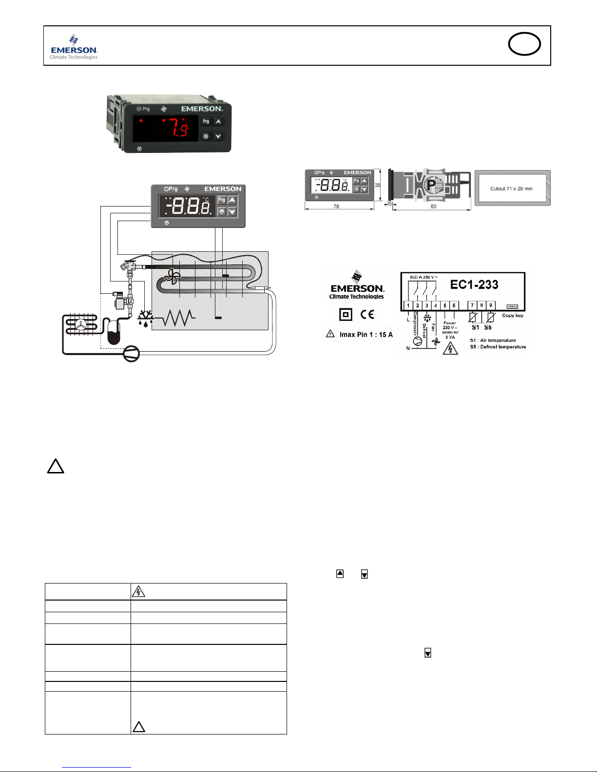
The EC1-233 is a dedicated refrigeration controller which controls air temperature
and manages defrost and fan(s).
S1
S5
2
3
4
2
EC1_Blockdiagr.cdr
9
7
The ECN-Sxx air temperature sensor S1(7) is used for measuring the air
temperature and may be installed to measure either the air-in or air-out temperature
of the evaporator to feed a signal to the controller for controlling the thermostat
function. A relay output is used to control the refrigerant flow to the ThermoExpansion Valve by switching a solenoid valve (2) and / or the compressor. An
ECN-Sxx sensor S5 (9) is used for defrost termination and may be installed in
either the air outlet duct or inserted into the evaporator coil. The controller has
relay outputs to control the solenoid valve / compressor (2), defrost heater (3) and
evaporator fan (4). Please consult the technical data (right) for input and output
ratings. Refer to the parameter list on page 3.
!
Safety instructions:
• Read installation instructions thoroughly. Failure to comply can result in
device failure, system damage or personal injury.
• The product is intended for use by persons having the appropriate
knowledge and skills.
• Ensure electrical ratings per technical data are not exceeded. Maximum
current permitted through the common live terminal (pin1) is 15Amps.
• Mains voltage; Caution should be made when removing the electrical cover
against electrical shock
• Disconnect all voltages from system before installation.
• Keep temperatures within nominal limits.
• Comply with local electrical regulations when wiring
Technical Data
Power supply
230VAC ±10%; 50/60 Hz; Class II
Power consumption 3VA max.
Communication n/a
Connector size Fixed screw terminals
wire size 0.14 … 1.5 mm
2
Temperature
storage
operating
-20 … +65°C
0 … +60°C
Humidity 0…80% r.h. non condensing
Protection class IP65 (front protection with gasket)
Output relays (3) SPST contacts, AgCdO, sealed
Inductive (AC15) 250V/2A
Resistive (AC1) 250V/8A;
!
Max. current 15A total supply current on pin1
Mounting
The EC1-233 can be mounted into a panel with a 71 x 29 mm cutout. See
dimensional drawing below for space requirements including rear cable protector.
Remove cable protector and mounting clips. (Move clip away from front side while
pushing at point P see dimensional drawing below).
Push controller into panel cutout (1) ensuring the gasket is positioned on the outer
surface.
Place the mounting clip onto the controller ensuring the spring is nearest the panel.
Push each clip forward until the controller is firmly held in place. The spring on the
clip should be compressed and the gasket firmly secured to prevent dust and
moisture ingress.
Electrical Installation
Connect wires to terminals as per diagram below and replace cable protector at rear
side. Refer to the electrical wiring diagram (below) for electrical connections. A
copy of this diagram is mounted on the controller. Use connection wires/cables
suitable for 90°C operation (EN 60730-1)
EC1 analog inputs are for dedicated sensors only and should not be connected to
any other devices. The controller has an internally mounted transformer allowing a
“mains” 230V 50/60Hz power supplier to be connected directly.
Important: Keep controller and sensor wiring well separated from mains wiring.
Minimum recommended distance 30mm.
Recommended Sensor Positions in Detail:
(7) ECN-Sxx air-in temperature sensor, S1: Position centrally below the air inlet
grille. In applications where the average ambient temperature is above 25°C, it may
be advisable to mount the air sensor in the lower air discharge duct (air-out of the
evaporator).
The air temperature sensor should be mounted on spacers in the air duct so that
there is airflow around it and it is not in contact with any surface material which
could produce a false temperature reading.
(9) ECN-Sxx defrost temperature sensor, S5: Position in the evaporator,
asymmetric closer to the expansion valve or in the air-outlet duct immediately after
the evaporator (only if S1 is mounted in the air-in duct).
Caution: The sensor cables can be extended if necessary. The connection must be
protected against water and dust.
Setup and Parameter Modification Using the Keypad
The parameters can be accessed via the 4-button keypad or may be more efficiently
programmed using a copy key. Refer to further details below. The parameters are
arranged in two sections; user and administration allowing two levels of access.
Security lock for parameter modification:
Press the
and buttons simultaneously for 10 seconds to unlock/lock the
controller parameters. “On” (unlocked) / “OF
F” (locked) will be displayed on the
screen respectively. When locked, the parameters may be visualized but cannot be
modified.
User parameters:
• Press the Prg button for more than 3 seconds. When active, the “prg” LED will
be illuminated and the first parameter “St” will be displayed.
To modify parameters see Parameters modification below.
Administration parameters:
• Press the Prg simultaneously with the
button for more than 10 seconds. When
active, the “prg” LED will be illuminated and the first parameter “St” will be
displayed.
To modify parameters see Parameters modification below.
• When parameter programming has been completed, press the Prg button to revert
back to operation mode. The Prg LED will be turned off.
Page 2
EC1-233_65150_EN_R02.doc Replacement for R01 2 / 2 Part No. 864 908 07.07.2008
EC1-233 Display Case and Coldroom Controller
Operating Instructions
GB
Parameter Modification: Procedure
• When the Prg LED is illuminated the parameters may be modified and the first
parameter “St” will be displayed.
• Press the Prg button again to display the current value associated with the
parameter.
• Press
or to increase or decrease the value. Pressing either button for 3
seconds will increase the speed of value change.
• Press the Prg button again to display the current parameter; “St”
• Press
repeatedly to show the next parameter code to be changed;
• Press the Prg button again to display the current value associated with the
parameter and the
or to increase or decrease the value.
• Repeat the procedure from the beginning "press
repeatedly to show..."
To exit and save the new settings:
• Press Prg for 3 seconds to confirm the new values and exit the parameters
modification procedure. The Prg LED will be turned off.
• Alternatively avoid pressing any button for at least 15 seconds and the controller
will automatically revert to the operation mode; controller “times out”.
• If any parameter is modified and the controller then times out, the new setting
will be automatically saved.
Copy Key Procedure
Upload procedure:
• With the controller powered, plug the copy key into the mini USB.
• Press the
button and the controller will display “UPL”.
• Press the PRG button to start the upload process to the copy key.
• Turn 230V power off before removing the copy key from the controller.
Download procedure:
• Turn 230V power off before inserting the copy key into the controller.
• Turn 230V power on. The controller will automatically detect the copy key is
present and start downloading the stored parameters into the controller. “DOW”
will be displayed on the controller during downloading process.
• Turn 230V power off before removing the copy key from the controller or the
data will be corrupted.
• Turn 230V power on and check the parameter values following the parameter
modification procedure above.
Caution:
DO NOT turn the controller off during this process. The control temperature will
be displayed when the process has been completed. ”Err” will be displayed if there
is an error during the upload/download procedure.
Any attempt to download a second set of parameter into the copy key will
automatically overwrite the original set.
Defrost Activation:
A defrost cycle can be activated locally from the keypad:
• Press the button for more than 3 seconds, the defrost cycle is activated and
the defrost LED will be illuminated (only if S5< value of parameter dt).
Continuous Cooling Demand Activation:
The controller can be set to continuous cooling:
• Press
the button for more than 3 seconds, the controller will be forced into the
cooling mode and the cooling LED will be illuminated.
• Press
the button for more than 3 seconds again to stop the continuous cooling
process.
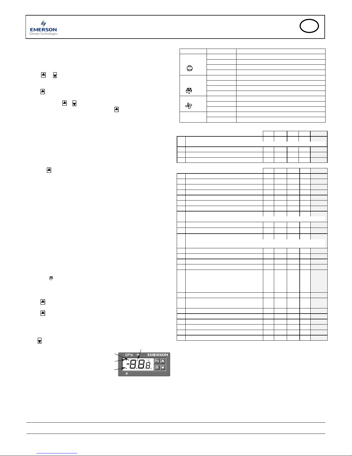
Display of Data:
During normal operation, the display will show the temperature measured by the
S1 air sensor.
Press
to display the current value associated with the defrost termination sensor.
LED displayed when:
Parameter alteration mode is active.
Compressor / Cooling relay active
Defrost heater relay active
Fan relay active
Note: A blinking LED indicates the respective relay is inhibited from becoming
active due to a time delay or an active alarm condition
LED Indication
Indicator Status Function
OFF Cooling relay inactive: cooling off
Blinking Compressor start delay
ON Cooling relay active: cooling on
Cooling
Blinking: fast Cooling relay active: continuous cooling
OFF Defrost relay inactive: defrost off
ON Defrost relay active: defrost on
Blinking Defrost relay inactive: drain down
Defrost
Blinking: fast Defrost relay active: forced defrost
OFF Fan relay inactive: fan off
Blinking Fan start delay
Fan
ON Fan relay active: fan on
OFF Normal working mode
Prg
ON Controller in programming mode
List of Parameters
USER
Min Max Unit Def.
Custom
St Temperature control setpoint r1 r2 °C -5.0
cut in = set-point + difference; cut out = set-point
rd Control deadband differential 1.0 +25.0 K 2.0
dP Max defrost duration 0 255 min 30
dI Defrost interval (0.1 h = 6 min.) 0.0 99.9 h 6.0
Factory default settings are all in °C. Refer to parameter /5 for °F settings
ADMINISTRATOR
Min Max Unit Def.
Custom
r1 Minimum setpoint -45.5 St °C -20.0
r2 Maximum setpoint St 110 °C 20.0
/C Air temperature alignment for S1 -10.0 +10.1 K 0.0
/d Defrost temperature alignment for S5 -10.0 +10.1 K 0.0
C2 Compressor start delay time 0 50 min 3
C3 Minimum emergency RUN time 0 255 min 45
C4 Maximum emergency OFF time 0 255 min 15
/5 Temperature Unit °C °F - °C
Note: When /5=°F all temperature parameters must be entered in °F or Rankin
d0 Defrost type: EL = electric; HtG = off cycle EL
dt Defrost termination temperature -45.5 +49.9 °C 10
/7 Display during defrost rt
rt: Air temperature (S1)
lt: Defrost start-up temperature
SEt: Air setpoint temperature
dEF: “dEF” displayed
A3 Display delay after defrost 0 255 min 30
d7 Drain down time: cooling restart delay 0 255 min 2
d4 Defrost at start-up y = yes, n = no n
d5 Defrost delay after start-up 0.0 24.0 h 0.0
F1 Fan mode:
C-n: start/stop with cooling, Off during defrost
O-n: continuously on, Off during defrost
C-Y: start/stop with cooling, ON during defrost
O-Y: continuously on, ON during defrost
C-n
Fd Fan delay after defrost 0 255 min 10
Ft On temp differential after defrost
Diff: Air temp. (S1) – Defrost temp. (S5)
0.0 +50.0 °C 10.0
AH
High temp alarm limit AL 110 °C 110
AL Low temp alarm limit -45.5 AH °C -45.5
A1 Air temp alarm delay 0 255 min 15
A2 Air temp. alarm delay after start-up 0 255 min 60
Ert Temperature sensor failure delay 0 255 min 0
FSt Fan stop temperature setpoint -45.5 +49.9 °C 10.0
Alarm Codes
AH High temperature alarm
Upper control temp alarm limit (AH) exceeded beyond delay time (A1)
AL Low temperature alarm
Lower control temperature alarm limit (AL) exceeded beyond delay time
(A1)
Er Sensor error
Air or defrost sensor open circuit
Compressor run & off times are set by parameters C3 and C4
Emerson Electric GmbH & Co OHG is not to be held responsible for erroneous
literature regarding capacities, dimensions, applications, etc. stated herein.
Products, specifications and data in this literature are subject to change without
notice. The information given herein is based on technical data and tests which
ALCO CONTROLS believes to be reliable and which are in compliance with
technical knowledge of today. It is intended only for use by persons having the
appropriate technical knowledge and skills, at their own discretion and risk. Since
conditions of use are outside of ALCO'S control we cannot assume any liability for
results obtained or damages occurred due to improper application.
This document replaces all former versions
Emerson Electric GmbH & Co OHG - Postfach 1251 - Heerstraße 111 - 71332 Waiblingen - Germany - Phone +49 7151 509 0 - Fax +49 7151 509 200
www.emersonclimate.eu
 Loading...