

Page 1
Thru-The-Wall Air Conditioner
MODEL:
8, 000 BTU
10, 000 BTU
12, 000 BTU
14, 000 BTU
Thank you very much for purchasing our air conditioner.Please read this owner`s manual carefully before
using your air conditioner.
Page 2

Page 3
Page 4

INTRODUCTION
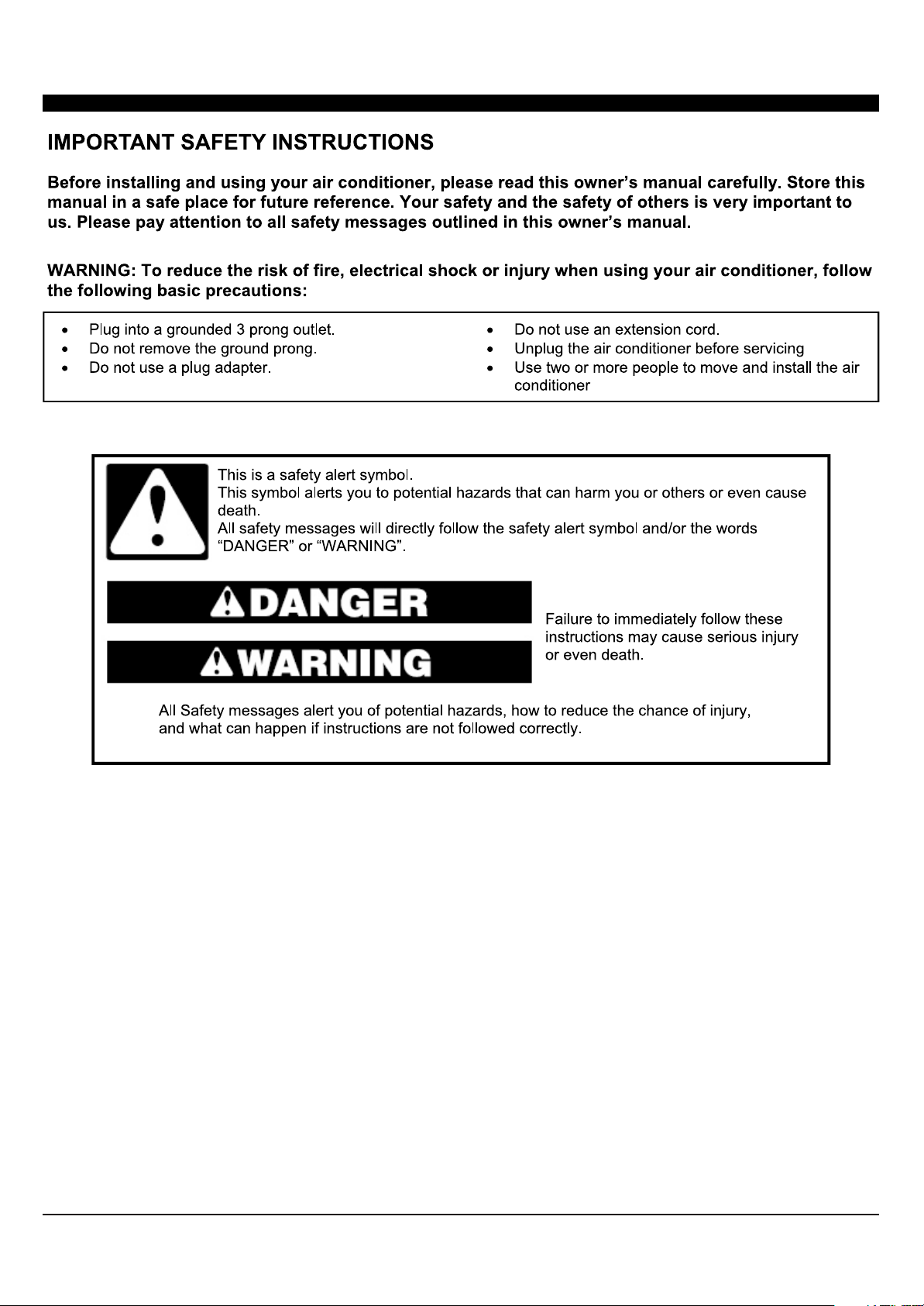
IMPORTANT SAFETY INSTRUCTION ...........................................................................
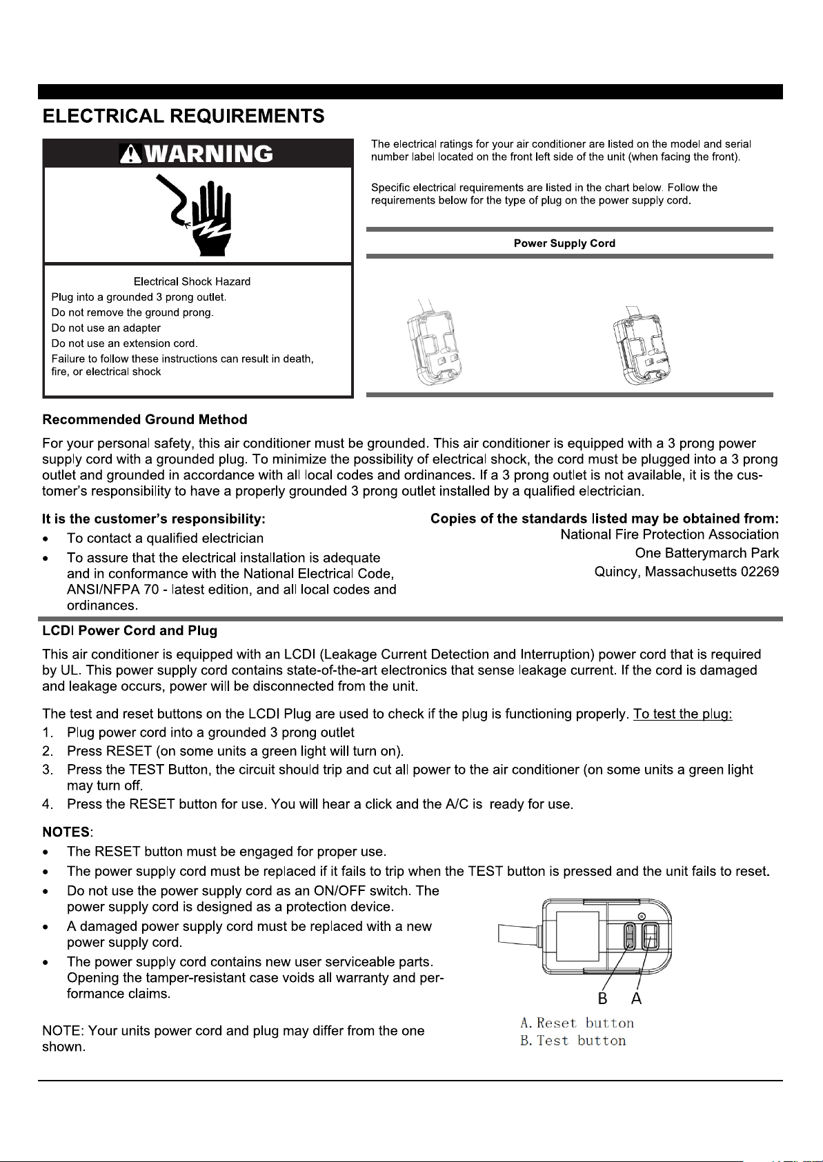
ELECTRICAL REQUIREMENTS
PACKING LIST ............................................................................................................
INSTALLATION & ASSEMBLY INSTRUCTIONS ..............................................................
USING YOUR AIR CONDITIONER ................................................................................
OPERATING YOUR AIR CONDITIONER
CARE AND CLEANING ................................................................................................
TROUBLESHOOTING .................................................................................................
...................................................................................
........................................................................
1
2
3
4
8
10
11
12
Page 5
1
Page 6
8K/10K/12K/14K Cooling
8K Cooling & Heating
10K/12K/14K Cooling &
Heating
2
Page 7

P AP T QUANTIT YIMAG E
or
Through-The-Wall Air Conditioner
Remote Control
Trim Frame 1 (Left&Right legs)
Trim Frame 2 (Top&Bottom legs)
Grille Aluminum
Rear plastic net
1/2" Long Hex-head Screw
1
1
2
2
1
1
4
Grounding wire with tooth washer
P AP T QUANTIT YDimensio n
Seal spong e1’’x3/4’’x14’’ 2
Seal spong e1’’x3/8’’x14’’ 2
Seal spong e1’’x3/8’’x25’’
Seal spong e1’’x1 1/2’’x25’’ 3
Seal spong e1’’x1 1/2’’x14’’ 2
Seal spong e1’’x1 1/2’’x84’’
Seal cotton3 3/4’’x1 1/2’’ x4 ’’ 4
1
3
1
Seal cotton3/4’’x1 1/2’’x17’’ 2
3
Page 8

Universal Wall-Sleeve Dimensions
1. Identify the wall-sleeve brand for your preparing, from the below chart.
Brand
Wall-sleeve Dimensions
Frigidaire
White-Westinghouse
Carrier(52 S eries)
GE/Hotpoint/Aman a
Whirlpool
Fedders/Emerson/Friedrich(WSE)
Sears/Kenmore
Carrier(51S S eries)
Emerson/Fedders
Friedrich(USC)
Brand Brand
15 1/4’’ 25 1/2’’ 16’’ 17 1/2’’ or 22’’
15 5/8’’
16 1/2’’ 25 7/8’’ 17 1/8’’ or 23’’
16 3/4’’
16 7/8’’ 25 3/4’’ 18 5/8’’
15 3/4’’ 26 3/4’’
15 1/2’’ 25 7/8’’ 16 3/4’’
26’’
27’’
Brand
16 7/8'’
16 3/4’’ or 19 3/4’’
15’
’
NOTE
• All wall sleeves used to mount the new air conditioner must be in sound structural condition and have a rear
grille that sec urely attached to the sleeve, or rear flange that serves as a sto p for the air conditioner.
• For new or replacement installations, a Frigidaire Sleeve Kit (EA108T) is recommended.
CAUTION
When installatio n is complete, replacement unit must have rearward slope as shown in Fig 1.
2. Remove old Air Conditioner from wall sleeve and prepare as followings:
--- Clean interior (Do not disturb seals).
--- Check the wall sleeve is securely fastened in wall before installing. Add more nails or screws if needed.
--- Repair painted surface if needed.
3. If the ground wire hole does not exist, drill a 3/16'' pilot hole for the grounding screw through the left hand
side of the sleeve, in a clear area about 3 inches max. back from the front edge a s below. Pull
the loose
end of the ground wire out of the front of the sleeve and bend it away from the opening. T hi s will be
attached to th e a ir conditioner once installed.
4. Install new unit into wall sleeve.
5. To attach ground wire to the new unit, remove the screw from the left side front.
6. Assemble and install the Trim Frame.
4
Page 9

NOTE
• This units increased pe rformance characteristics is th e r es ul t of having two rear intakes.
• It is very importan t that these installation instructions are followe d so your unit can operate at maximum
efficiency.
• If there is an existing sleeve and rear grille, please check whether the dimensi on is suitable or not, otherwise
replace th em .
Existing Frigidaire sleeves may have older single sided intake grilles,as pictured below
• Remove t he existin g g rille an d s ave the mount ing screws.
• Pl ace t he gri l l e i ncl uded wi t h your new ai r condi t i oner
t owar ds t he i nsi de r ear of t he sl eeve.
• At t ac h t he new gr i l l e by al i gni ng t he f our mount i ng hol es.
• Re- in ser t t he sel f - t appi ng scr ews i nt o t he nyl on r et ai n
2. Grille Remo val
Important: Sing le intake grille must be removed when used with dual in take TTW unit.
Warning: When removing grille, pr ot ec t
strapping looped through the grille and secured wi th a knot.
Holding the grille by the leash with one hand the retaining sc re ws can be removed and the grille can be brought
inside throug h the front of the sleeve.
from falling by securing with a leash. This can be fastened from cord or
5
Page 10

Direct Unit Mounti ng
In cases where the dual intake grille c annot be mounted directly to the sleeve it is desirable t o attach the
grille to the back of the TTW uni t to th e hole predrilled in the unit.
1. Attach the 2 s eals(1''x3/8 ''x14''), as Fig. 1.
2. Position th e grill e over the rear of the unit making sure that:
a.The double se t of screw holes are at the bottom.
b.The intake fin s on either side are pointed away from the unit.
3. Align the top of the grille with the top of the unit. The overhang on each side is
4. If the unit has no t been predrilled (some models), carefully drill 4-1/8'' hole s through the grille and into the side
flange of the uni t approximately 1 1/2'' to 2'' from the to p and bottom, as Fig 2 or 3. (Be careful not to break the
copper pipe)
5. Install 4-#8 self -t apping screws to affix the grille to the unit.
6. Inser
t the unit into the sleeve.
equal.
Grille to Sleeve Attachmen t
In cases where t he dual intake grille fits inside the sleeve and the grille flange overlaps the sleeve flange, direct
attachment may be possible.
IMPORTANT
If the sui
table grille is not used, it may lead to product damage and possible failure .
6
Page 11

Seal Installation
1. 1''x3/8''x25'' long seal in the center at the top of the sleeve. Remove the back paper and press into position.
2. 1''x3/8''x14'' seals to the left and right sides of the sleeve.
3. Cut 1''x3/8''x25'' long seals to 14'' long each and attach to the vertical sections of the grille as shown.
4. 1/2''x3 1/2''x1 1/2'' centering blocks one on each side wall. Place in center of side wall with the tapered end
facing the opening.
5. Gently slide unit into sleeve.
Ground Wire Installation
1. Install screw end of ground wire into inside of sleeve according to preparation instruction.
2. Before sliding unit all the way back remove second screw from left side of unit.
3. Remove plastic washer from screw.
4. Screw the other end of the ground wire into the unit as shown. Make sure the toothed washer is against the
cabinet.
5. Slide unit completely to the rear.
Non-Frigidaire Dual Intake Grille
In case where the existing sleeve is a non-Frigidaire sleeve but is installed with a dual intake grille. The existing
grille may be left in place. Make sure the outer 3 1/2'' to 4 1/2'' louvers are angled from the left and right sides of
the sleeve toward the center, as Fig. 1. This provides proper flow of outside air into the unit.
From the installation kit, apply two 1''x3/4''x14'' seals along the flat metal flange of the condenser, as Fig. 2.
7
Page 12

Insert the unit with the seal into the sleeve pushing it all the way to rear making sure the seals are against the
rear grille. The seals are necessary to reduce recirculation of hot air into the intakes which would reduce system
reduce system performance.
An option is to purchase 3/4'' diamond cut aluminum grille and cut it to fit inside the sleeve. Secure it with screws.
Attach the dual intake grill directly to the back of the unit. Slide the entire unit into the sleeve and seal with the
stuffing seal supplied with the kit.
Trim Kit Installation Instructions
1. Install the 1''x1''x84'' long stuffer seal between the wall sleeve and the unit. A flat-bladed screwdriver or putty
knife is needed.
2. Assemble the trim frame by inserting the top and bottom pieces into side pieces and snapping into place.
3. Pull the cord through the trim frame and slide the trim over the unit until flush with the wall.
Energy saving
use an appropriately sized cover to provide additional insulation and air sealing when the unit is not in use
during the off-using-season.
suggestion: In order to reach the maximum energy saving and comfortable, it is necessary to
8
Page 13

For Cooling model
AUTO
SPEED
For Heating model
AUTO
SPEED
1. Without timer setting,the
Digital Display:
1
2
AUTO
MODE
3
456789
1
2
AUTO
MODE
HEAT
3
456789
operation mode is Cooling,Dry, Fan and Auto,and
the set temperature will be displayed.
Time will be displayed under timer setting.
and Button:2. Use these buttons on the
control panel and remote to increase or decrease
the Set Temperature or Timer.
Temperature range: 61 ~88 or 16 ~31 .
3. Turn the air conditioner on and
Power Button:
off.
Press the mode button to cycle
4. Mode Button:
through the various modes: Cool, Dry, Fan and
Auto, or Heat.
Cool Mode: The cooling function allows the air
conditioner to cool the room and at the same time
reduces humidity. Press the MODE button to
activate the cooling function. To optimize the
function of the air conditioner, adjust the
temperature and the speed by pressing the button
indicated.
Dry Mode: This function reduces the humidity of
the air to make the room more comfortable. Press
MODE button to set the DRY mode. An automatic
function of alternating cooling cycles and air fan
is activated.
Fan Mode: The Fan Mode works in only
ventilation. Press MODE
button to set the FAN
mode. With pressing FAN SPEED button the
speed changes in the following sequence: Hi, Med
and Lo in FAN mode. The remote control also
stores the speed that was set in the previous
mode of operation.
Auto Mode: In AUTO mode the unit automatically
chooses the fan speed and the mode of operation
(COOL,DRY or FAN).In this mode the fan speed
and the temperature are set automatically
according to the room temperature (tested by the
temperature sensor which is incorporated in
indoor unit.).
Heat Mode: The heating function allows the air
conditione
r to heat the room. Press the MODE
button to activate the cooling function. To optimize
the function of the air conditioner, adjust the
temperature and the speed by pressing the button
indicated.
Use these buttons on the control
5. Timer Button:
panel and remote to set the Timer.
Timer Off: The timed stop is programmed by
pressing TIMER button. Set the rest time by
pressing the button or until the rest
time displayed is to your demand then press
TIMER button again.
Timer On: When the unit is off, press TIMER
button at the first time, set the temperature with
pressing the button or . Press TIMER
button at the second time, set the rest time with
pressing the button or . Press TIMER
button a third time, confirm the setting, then the
di
splay will show the time the machine will
automatically turn on.
Note: It can be set to automatically turn off or on in
0.5-24 hours. Each press of the
buttons will increase or decrease the timer. The
Timer can be set in 0.5 hours increment below 10
hours and 1 hour increment for 10 hours or above.
The SET light will turn on while setting.
To cancel the set function, press the TIMER
button again.
the
9
Page 14
6. Eco Button:
When the unit is in ECO mode, the
light will turn on. In ECO mode, the unit will
turn-off once the room is cooled to the user set
temperature. The fan will also be off at this point.
The unit will turn back on when the room
temperature rises above the user set temperature.
Before the compressor stars, the fan motor will
run for a while, then it will stop for a while-and will
repeat to provide a much more comfortable-feeling
and save energy.
7. Sleep Button:
Press the SLEEP button, the Sleep
Light will be on after 10s, and all the left lights will
be off. In SLEEP mode, the air-conditioner will
automatically adjust the temperature and fan
speed to make the room more comfortable during
the night. For cooling mode, the set temperature
will automatically raise by 1 every 30-60 minutesF
and at most change six times until the set
temperature is 82 . For heating mode, the set
F
temperature will automatically decrease by 1
every 30-60 minutes and at most change six times
until the set temperature is 75 .
F
And every running time depends on the set
temperature.
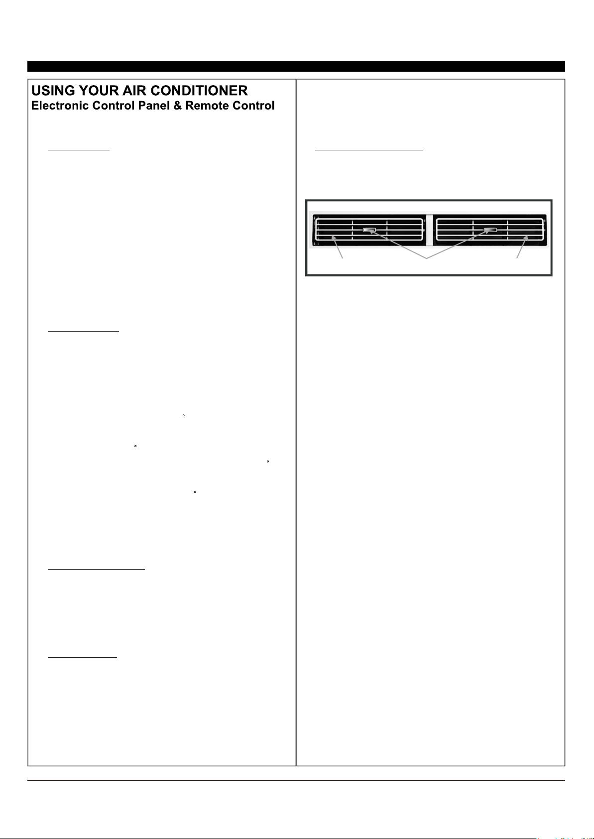
10.
Directional Louvers:
To direct the airflow,
horizontal wheel to control the horizontal direction,
air deflector to control the vertical direction.
horizontal wheelair deflector air deflector
F
8. Fan Speed Button:
Press the FAN SPEED button
to choose the fan speed options. You can choose
Hi, Med, Lo or auto speed in COOL mode and
choose Hi, Med, Lo in FAN mode.
9.
The Led (light ) will illuminate after
500 hours of operation as a reminder to clean the
Air cleaning the filter,press the Check Filter button
and the light will turn off.
Filter Button:
10
Page 15

1
2
3
4
5
7
8
9
6
10
3
HEAT
*For mark 6 button, it is AUTO MODE for coolling only, and it is
HEAT for heating model.
1. Turn the air conditioner on and off.Power:
2. Press the COOL button to COOL mode.Cool:
and :3. Use these buttons on the control
panel and remote to increase or decrease the
Set Temperature or Timer. Temperature range:
61 ~88 or 16 ~31 .
Press the SLEEP button, the Sleep
4. Sleep:
Light will be on after 10s, and all the left
lights will be off. In SLEEP mode, the
air-conditioner will automatically adjust the
temperature and fan speed to make the room
more comfortable during the night. The set
temperature will automatically raise by 1
every 30-60 minutes and at most change six
times until the set temperature is 28 . And
every r
temperature.
unning
time depends on the set
Use these buttons on the control panel
5. Timer:
and remote to set the Timer.
Timer Off: The timed stop is programmed by
pressing TIMER button. Set the rest time by
pressing the button or until the rest
time displayed is to your demand then press
TIMER button again.
Timer On: When the unit is off, press TIMER
button at the first time, set the temperature with
pressing the button or . Press TIMER
button at the second time, set the rest time with
pressing the button or . Press TIMER
button at the third time, confirm the sett
then the display will show the time the machine will
automatically turn on.
Note: It can be set to automatically turn off or on
in 0.5-24 hours. Each press of the
buttons will increase or decrease the timer. The
Timer can be set in 0.5 hours increment below
10 hours and 1 hour increment for 10 hours or
above. The SET light will turn on while setting.
To cancel the setted function, press the TIMER
button again.
In AUTO mode the unit automatically
6. a.Auto Mode:
chooses the fan speed and the mode of operation
(COOL,DRY or FAN).In this mode the fan speed
and the temperature are set automatically according
to the room temperature (tested by the temperature
sensor which is incorporated in the indoor unit.).
It is for cooling only model.
b.HEAT:
Press the HEAT button to HEAT mode.
It is for heating model.
Press the FAN SPEED button to
7. Fan Speed:
choose the fan speed options. You can choose
Hi, Med, Lo or auto speed in COOL mode and
choose Hi, Med, Lo in FAN mode.
Press the DISPLAY button to switch on/off
8. Display:
all lights or LED display.
When the unit is in ECO mode, the light
9.
Eco:
will turn on. In ECO mode, the unit will turn-off
once the room is cooled to the user set
temperature. The fan will also be off at this
point. The unit will turn back on when the room
temperature rises above the user set
temperature.Before the compressor stars, the fan
motor will run for a while, then it will stop for a
while-and will repeat to provide a much more
comfortable-feeling and save energy.
Fan Only:
Press the Fan Only button to FAN
10.
ONLY mode.
ing,
11
Page 16

FIG.21
FIG.21
12
Page 17

13
Page 18

For any questions or Technical Support,
Please Call Customer Service: 1-844-801-8880
14
Page 19

Page 20

 Loading...