

Page 1

User Guide
AC variable speed drive for servo
motors
Part Number: 0475-0001-05
Issue: 5
Page 2

Original Instructions
For the purposes of compliance with the EU Machinery Directive 2006/42/EC:
General Information
The manufacturer accepts no liability for any consequences resulting from inappropriate, negligent or incorrect installation or
adjustment of the optional operating parameters of the equipment or from mismatching the variable speed drive with the motor.
The contents of this guide are believed to be correct at the time of printing. In the interests of a commitment to a policy of continuous
development and improvement, the manufacturer reserves the right to change the specification of the product or its performance, or
the contents of the guide, without notice.
All rights reserved. No parts of this guide may be reproduced or transmitted in any form or by any means, electrical or mechanical
including photocopying, recording or by an information storage or retrieval system, without permission in writing from the publisher.
Drive software version
This product is supplied with the latest software version. If this drive is to be connected to an existing system or machine, all drive
software versions should be verified to confirm the same functionality as drives of the same model already present. This may also
apply to drives returned from an Emerson Industrial Automation Service Centre or Repair Centre. If there is any doubt please contact
the supplier of the product.
The software version of the drive can be checked by looking at Pr 11.29 and Pr 11.34. This takes the form of xx.yy.zz where Pr 11.29
displays xx.yy and Pr 11.34 displays zz. (e.g. for software version 01.01.00, Pr 11.29 = 1.01 and Pr 11.34 displays 0).
Environmental statement
Emerson Industrial Automation is committed to minimising the environmental impacts of its manufacturing operations and of its
products throughout their life cycle. To this end, we operate an Environmental Management System (EMS) which is certified to the
International Standard ISO 14001. Further information on the EMS, our Environmental Policy and other relevant information is
available on request, or can be found at:
http://www.emersonindustrial.com/en-EN/controltechniques/aboutus/environment/Pages/environment.aspx
The electronic variable-speed drives manufactured by Emerson Industrial Automation have the potential to save energy and (through
increased machine/process efficiency) reduce raw material consumption and scrap throughout their long working lifetime. In typical
applications, these positive environmental effects far outweigh the negative impacts of product manufacture and end-of-life disposal.
Nevertheless, when the products eventually reach the end of their useful life, they must not be discarded but should instead be
recycled by a specialist recycler of electronic equipment. Recyclers will find the products easy to dismantle into their major component
parts for efficient recycling. Many parts snap together and can be separated without the use of tools, while other parts are secured
with conventional fasteners. Virtually all parts of the product are suitable for recycling.
Product packaging is of good quality and can be re-used. Large products are packed in wooden crates, while smaller products come
in strong cardboard cartons which themselves have a high recycled fibre content. If not re-used, these containers can be recycled.
Polythene, used on the protective film and bags for wrapping product, can be recycled in the same way. Emerson Industrial
Automations' packaging strategy prefers easily-recyclable materials of low environmental impact, and regular reviews identify
opportunities for improvement.
When preparing to recycle or dispose of any product or packaging, please observe local legislation and best practice.
REACH legislation
EC Regulation 1907/2006 on the Registration, Evaluation, Authorisation and restriction of Chemicals (REACH) requires the supplier
of an article to inform the recipient if it contains more than a specified proportion of any substance which is considered by the European
Chemicals Agency (ECHA) to be a Substance of Very High Concern (SVHC) and is therefore listed by them as a candidate for
compulsory authorisation.
For current information on how this requirement applies in relation to specific Emerson Industrial Automations’ products, please
approach your usual contact in the first instance. Emerson Industrial Automations’ position statement can be viewed at:
www.emersonindustrial.com/en-EN/controltechniques/aboutus/environment/reachregulation/Pages/reachregulation.aspx.
Copyright © September 2015 Emerson Industrial Automation.
The information contained in this guide is for guidance only and does not form part of any contract. The accuracy cannot be guaranteed
as Emerson have an ongoing process of development and reserve the right to change the specification of their products without notice.
Control Techniques Limited. Registered Office: The Gro, Newtown, Powys SY16 3BE. Registered in England and Wales. Company
Reg. No. 01236886.
Moteurs Leroy-Somer SAS. Headquarters: Bd Marcellin Leroy, CS 10015, 16915 Angoulême Cedex 9, France. Share Capital: 65 800
512 €, RCS Angoulême 338 567 258.
Issue Number: 5
Software: 01.06.00 onwards
For patent and intellectual property related information please go to: www.ctpatents.info.
Page 3
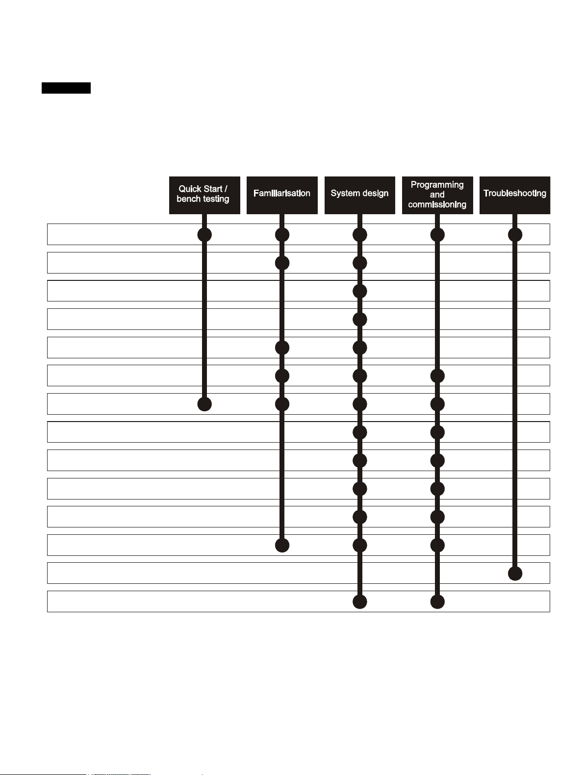
How to use this guide
NOTE
1 Safety information
2 Product information
3 Mechanical installation
4 Electrical installation
5 Getting started
6 Basic parameters
7 Running the motor
8 Optimization
9 SMARTCARD operation
11 Advanced parameters
12 Technical data
13 Diagnostics
14 UL listing information
10 Onboard PLC
This User Guide provides information for operating the drive from start to finish.
The information is in logical order, taking the reader from receiving the drive through to fine tuning the performance.
There are specific safety warnings throughout this guide, located in the relevant sections. In addition, Chapter 1 Safety
Information on page 6 contains general safety information. It is essential that the warnings are observed and the
information considered when working with or designing a system using the drive.
This map of the user guide helps to find the right sections for the task you wish to complete:
Page 4

Contents
1 Safety Information .................................6
1.1 Warnings, Cautions and Notes .............................6
1.2 Electrical safety - general warning ........................6
1.3 System design and safety of personnel ................6
1.4 Environmental limits ..............................................6
1.5 Access ...................................................................6
1.6 Fire protection .......................................................6
1.7 Compliance with regulations .................................6
1.8 Motor .....................................................................6
1.9 Mechanical brake control ......................................6
1.10 Adjusting parameters ............................................6
1.11 Electrical installation ..............................................6
2 Product information ..............................8
2.1 Introduction ...........................................................8
2.2 Drive ratings ..........................................................8
2.3 Drive model numbers ............................................9
2.4 Drive nameplate description ..................................9
2.5 Features of the drive ...........................................10
2.6 Options ................................................................11
2.7 Items supplied with the drive ...............................14
3 Mechanical installation .......................15
3.1 Safety information ...............................................15
3.2 Planning the installation ......................................15
3.3 Solutions Module / keypad installation / removal 16
3.4 Drive dimensions .................................................17
3.5 External EMC filter rating ....................................18
3.6 Optional braking resistor .....................................19
3.7 Terminal torque settings ......................................20
3.8 Routine maintenance ..........................................20
4 Electrical installation ...........................21
4.1 Power terminal connections ................................22
4.2 Ground connections ............................................23
4.3 AC supply requirements ......................................23
4.4 DC bus design .....................................................24
4.5 DC drive voltage levels .......................................24
4.6 Ratings ................................................................25
4.7 Output circuit and motor protection .....................25
4.8 Braking ................................................................26
4.9 Ground leakage ...................................................27
4.10 EMC (Electromagnetic compatibility) ..................28
4.11 Internal and external conducted emissions
conformity ............................................................30
4.12 Serial communications connections ....................31
4.13 Control connections ............................................32
4.14 Control terminals .................................................34
4.15 Encoder connections ...........................................37
4.16 Encoder terminals ...............................................38
4.17 Safe Torque Off ...................................................42
5 Getting started .................................... 43
5.1 User interfaces ................................................... 43
5.2 CT Soft ............................................................... 43
5.3 SYPTPro (Indexer & Plus only) .......................... 43
5.4 EZMotion PowerTools Pro ................................. 43
5.5 Keypad operation ............................................... 44
5.6 Understanding the display .................................. 44
5.7 Displaying parameters with non-default
values only ......................................................... 47
5.8 Displaying destination parameters only ............. 47
5.9 Communications ................................................ 47
6 Basic parameters ................................ 49
6.1 Single line descriptions ...................................... 49
6.2 Full descriptions ................................................. 54
7 Running the motor .............................. 60
7.1 Quick start Connections ..................................... 60
7.2 Quick Start set-up .............................................. 64
7.3 Setting up a feedback device ............................. 65
7.4 Setting up a buffered encoder output ................. 68
8 Optimization ........................................ 69
8.1 Motor map parameters ....................................... 69
9 EtherCAT interface ............................. 72
9.1 Features ............................................................. 72
9.2 What is EtherCAT? ............................................ 72
9.3 EtherCAT interface information .......................... 72
9.4 EtherCAT interface terminal descriptions ........... 72
9.5 Module grounding .............................................. 72
9.6 Network topology ............................................... 72
9.7 Minimum node-to-node cable length .................. 72
9.8 Quick start guide ................................................ 72
9.9 Quick start flowchart ........................................... 74
9.10 Saving parameters to the drive .......................... 75
9.11 EtherCAT interface Node address ..................... 75
9.12 EtherCAT interface RUN .................................... 75
9.13 Re-initializing the EtherCAT interface ................ 75
9.14 Process Data Objects (PDOs) ........................... 75
9.15 Service Data Object (SDO) parameter access .. 75
9.16 CANopen over EtherCAT (CoE) ........................ 76
9.17 Ethernet over EtherCAT (EoE) ........................... 80
9.18 Drive profile (DSP-402) support ......................... 81
9.19 Interpolated position mode ................................. 87
9.20 vl velocity mode .................................................. 88
9.21 Profile torque mode ............................................ 90
9.22 Homing mode ..................................................... 91
9.23 Cyclic sync position mode .................................. 94
9.24 Advanced features ............................................. 94
9.25 Advanced cyclic data configuration .................... 96
9.26 Internal shortcuts ................................................ 97
9.27 Quick reference .................................................. 98
4 Digitax ST User Guide
Issue: 5
Page 5

10 SMARTCARD Operation ...................101
10.1 Introduction .......................................................101
10.2 Transferring data ...............................................102
10.3 Data block header information ..........................104
10.4 SMARTCARD parameters ................................104
10.5 SMARTCARD trips ...........................................106
11 Onboard PLC .....................................108
11.1 Onboard PLC and SYPTLite .............................108
11.2 Benefits .............................................................108
11.3 Limitations .........................................................108
11.4 Getting started ..................................................108
11.5 Onboard PLC parameters .................................108
11.6 Onboard PLC trips ............................................109
11.7 Onboard PLC and the SMARTCARD ...............109
14 Diagnostics ........................................183
14.1 Trip indications ..................................................183
14.2 Alarm indications ...............................................198
14.3 Status indications ..............................................199
14.4 EtherCAT Diagnostics .......................................199
14.5 Network configuration objects ...........................200
14.6 Diagnostic parameters ......................................200
14.7 Drive trip display codes .....................................200
14.8 EtherCAT interface temperature .......................201
14.9 EtherCAT interface serial number .....................201
14.10 EtherCAT interface error codes ........................201
14.11 Error handling ...................................................201
14.12 Critical task % free ............................................203
14.13 SDO abort codes ..............................................203
14.14 FLASH file system % free .................................203
12 Advanced parameters .......................110
12.1 Menu 1: Speed reference .................................116
12.2 Menu 2: Ramps .................................................120
12.3 Menu 3: Speed feedback and control ...............124
12.4 Menu 4: Torque and current control ..................127
12.5 Menu 5: Motor control .......................................130
12.6 Menu 6: Sequencer and clock ..........................133
12.7 Menu 7: Analog I/O ...........................................135
12.8 Menu 8: Digital I/O ............................................138
12.9 Menu 9: Programmable logic, motorized
pot, binary sum and timers ................................141
12.10 Menu 10: Status and trips .................................144
12.11 Menu 11: General drive set-up .........................146
12.12 Menu 12: Threshold detectors, variable
selectors and brake control function .................147
12.13 Menu 13: Position control .................................152
12.14 Menu 14: User PID controller ............................156
12.15 Menus 15 and 16: Solutions Module set-up ......159
12.16 Menu 17: Motion processors .............................160
12.17 Menu 18: Application menu 1 ...........................163
12.18 Menu 19: Application menu 2 ...........................163
12.19 Menu 20: Application menu 3 ...........................163
12.20 Menu 21: Second motor parameters ................164
12.21 Menu 22: Additional Menu 0 set-up ..................165
12.22 Advanced features ............................................166
15 UL listing information .......................204
15.1 Common UL information ...................................204
15.2 AC supply specification .....................................204
15.3 Maximum continuous output current .................204
15.4 Common DC bus ..............................................204
15.5 DC Supplied drive .............................................205
15.6 UL listed accessories ........................................205
13 Technical Data ...................................173
13.1 Drive technical data ..........................................173
13.2 Optional external EMC filters ............................182
13.3 Overall EMC filter dimensions ...........................182
Digitax ST User Guide 5
Issue: 5
Page 6

Safety
WARNING
CAUTION
NOTE
Information
Product
information
Mechanical
installation
Electrical
installation
Getting
started
Basic
parameters
Running the
motor
Optimization
EtherCAT
interface
SMARTCARD
Operation
Onboard
PLC
Advanced
parameters
Technical
Data
Diagnostics
UL listing
information
1 Safety Information
1.1 Warnings, Cautions and Notes
A Warning contains information which is essential for
avoiding a safety hazard.
A Caution contains information which is necessary for
avoiding a risk of damage to the product or other equipment.
A Note contains information which helps to ensure correct operation of
the product.
1.2 Electrical safety - general warning
The voltages used in the drive can cause severe electrical shock and/or
burns, and could be lethal. Extreme care is necessary at all times when
working with or adjacent to the drive.
Specific warnings are given at the relevant places in this guide.
1.3 System design and safety of personnel
The drive is intended as a component for professional incorporation into
complete equipment or a system. If installed incorrectly, the drive may
present a safety hazard.
The drive uses high voltages and currents, carries a high level of stored
electrical energy, and is used to control equipment which can cause
injury.
Close attention is required to the electrical installation and the system
design to avoid hazards either in normal operation or in the event of
equipment malfunction. System design, installation, set-up and
maintenance must be carried out by personnel who have the necessary
training and experience. They must read this safety information and this
guide carefully.
The STOP and Safe Torque Off functions of the drive do not isolate
dangerous voltages from the output of the drive or from any external
option unit. The supply must be disconnected by an approved electrical
isolation device before gaining access to the electrical connections.
With the sole exception of the Safe Torque Off function, none of the
drive functions must be used to ensure safety of personnel, i.e.
they must not be used for safety-related functions.
Careful consideration must be given to the functions of the drive which
might result in a hazard, either through their intended behavior or
through incorrect operation due to a fault. In any application where a
malfunction of the drive or its control system could lead to or allow
damage, loss or injury, a risk analysis must be carried out, and where
necessary, further measures taken to reduce the risk - for example, an
over-speed protection device in case of failure of the speed control, or a
fail-safe mechanical brake in case of loss of motor braking.
The Safe Torque Off function has been approved by IFA as meeting the
requirements of the following standards, for the prevention of
unexpected starting of the drive:
EN 61800-5-2:2007 SIL 3
EN ISO 13849-1:2006 PL e
EN 954-1:1997 Category 3 (This standard is withdrawn and
should not be used for new designs, information provided for legacy
applications only).
The Safe Torque Off function may be used in a safety-related
application. The system designer is responsible for ensuring that the
complete system is safe and designed correctly according to the
relevant safety standards.
1.4 Environmental limits
Instructions regarding transport, storage, installation and use of the drive
must be complied with, including the specified environmental limits.
Drives must not be subjected to excessive physical force.
1.5 Access
Access must be restricted to authorized personnel only. Safety
regulations which apply at the place of use must be complied with.
1.6 Fire protection
The drive enclosure is not classified as a fire enclosure. A separate fire
enclosure must be provided. For details regarding fire protection please
refer to section 3.2.5 Fire protection on page 15.
1.7 Compliance with regulations
The installer is responsible for complying with all relevant regulations,
such as national wiring regulations, accident prevention regulations and
electromagnetic compatibility (EMC) regulations. Particular attention
must be given to the cross-sectional areas of conductors, the selection
of fuses or other protection, and protective ground (earth) connections.
Within the European Union, all machinery in which this product is used
must comply with the following directives:
2006/42/EC: Safety of machinery.
2004/108/EC: Electromagnetic Compatibility.
1.8 Motor
Ensure the motor is installed in accordance with the manufacturer’s
recommendations. Ensure the motor shaft is not exposed.
The values of the motor parameters set in the drive affect the protection
of the motor. The default values in the drive should not be relied upon.
It is essential that the correct value is entered in Pr 0.46 motor rated
current. This affects the thermal protection of the motor.
1.9 Mechanical brake control
The brake control functions are provided to allow well co-ordinated
operation of an external brake with the drive. While both hardware and
software are designed to high standards of quality and robustness, they
are not intended for use as safety functions, i.e. where a fault or failure
would result in a risk of injury. In any application where the incorrect
operation of the brake release mechanism could result in injury,
independent protection devices of proven integrity must also be
incorporated.
1.10 Adjusting parameters
Some parameters have a profound effect on the operation of the drive.
They must not be altered without careful consideration of the impact on
the controlled system. Measures must be taken to prevent unwanted
changes due to error or tampering.
1.11 Electrical installation
1.11.1 Electric shock risk
The voltages present in the following locations can cause severe electric
shock and may be lethal:
• AC supply cables and connections
• DC bus, dynamic brake cables and connections
• Output cables and connections
• Many internal parts of the drive, and external option units
Unless otherwise indicated, control terminals are single insulated and
must not be touched.
1.11.2 Isolation device
The AC supply must be disconnected from the drive using an approved
isolation device before any cover is removed from the drive or before
any servicing work is performed.
1.11.3 STOP function
The STOP function does not remove dangerous voltages from the drive,
the motor or any external option units.
6 Digitax ST User Guide
Issue: 5
Page 7

Safety
Information
Product
information
Mechanical
installation
Electrical
installation
Getting
started
Basic
parameters
Running the
motor
Optimization
1.11.4 Stored charge
The drive contains capacitors that remain charged to a potentially lethal
voltage after the AC supply has been disconnected. If the drive has been
energized, the AC supply must be isolated at least ten minutes before
work may continue.
Normally, the capacitors are discharged by an internal resistor. Under
certain, unusual fault conditions, it is possible that the capacitors may fail
to discharge, or be prevented from being discharged by a voltage
applied to the output terminals. If the drive has failed in a manner that
causes the display to go blank immediately, it is possible the capacitors
will not be discharged. In this case, consult Emerson Industrial
Automation or their authorized distributor.
1.11.5 Equipment supplied by plug and socket
Special attention must be given if the drive is installed in equipment
which is connected to the AC supply by a plug and socket. The AC
supply terminals of the drive are connected to the internal capacitors
through rectifier diodes which are not intended to give safety isolation. If
the plug terminals can be touched when the plug is disconnected from
the socket, a means of automatically isolating the plug from the drive
must be used (e.g. a latching relay).
1.11.6 Permanent magnet motors
Permanent magnet motors generate electrical power if they are rotated,
even when the supply to the drive is disconnected. If that happens then
the drive will become energized through its motor terminals.
If the motor load is capable of rotating the motor when the supply is
disconnected, then the motor must be isolated from the drive before
gaining access to any live parts.
EtherCAT
interface
SMARTCARD
Operation
Onboard
PLC
Advanced
parameters
Technical
Data
Diagnostics
UL listing
information
Digitax ST User Guide 7
Issue: 5
Page 8

Safety
Information
Product
information
Mechanical
installation
Electrical
installation
Getting
started
Basic
parameters
Running the
motor
Optimization
EtherCAT
interface
SMARTCARD
Operation
Onboard
PLC
Advanced
parameters
Technical
Data
Diagnostics
UL listing
information
2 Product information
2.1 Introduction
The Digitax ST family of servo drives are available with five levels of
intelligence:
• Digitax ST Base
• Digitax ST Indexer
• Digitax ST Plus
• Digitax ST EZMotion
• Digitax ST EtherCAT
The Digitax ST Base drive operates in velocity or torque modes and is
designed to operate with a centralized motion controller or as a
standalone drive.
The Digitax ST Indexer drive performs point-to-point motion profiling
including relative, absolute, rotary plus, rotary minus, registration and
homing motion. The Digitax ST Indexer will operate as a single
standalone system controller. Alternatively, the Digitax ST Indexer can
form part of a distributed system where commands are sent over a
fieldbus or through digital input/output signals. The Digitax ST Indexer
drive is commissioned using a simple and easy to use indexing tool that
resides within CTSoft, a set-up tool for Emerson Industrial Automation
products.
The Digitax ST plus drive offers all the features available o the Digitax
ST Indexer drive with the addition of performing complex motion as a
single axis or synchronized to a reference axis. This offers digital lock
and electronic camming via a virtual master reference. The Digitax ST
Plus drive is commissioned using a simple and easy to use indexing tool
that resides within CT Soft, a set-up tool for Emerson Industrial
Automation products.
For more complex systems using the Digitax ST Indexer and Digitax ST
Plus drives, an export feature is available that allows the user to import
applications into SYPTPro for further development.
The Digitax ST EZMotion drive is part of the Motion Made Easy family of
servo drives and allows the user to create programs to sequence
motion, I/O control, and other machine operations in one environment.
Digitax ST EZMotion also supports advanced functions such as a
Position Capture Object, Multiple Profile Summation, Queuing, and
Program Multitasking.
The Digitax ST EtherCAT drive offers onboard EtherCAT allowing the
product to be connected to an EtherCAT network as a slave device. It
can be used in a variety of applications, including those requiring
accurate synchronization and precise motion control.
All variants provide a Safe Torque Off function.
Four documentation guides are available for Digitax ST, these cover all
variants:
All guides are available for download at:
http://www.emersonindustrial.com/en-EN/controltechniques/downloads/
userguidesandsoftware/Pages/downloads.aspx
or
www.emersonindustrial.com/en-EN/leroy-somer-motors-drives/
downloads/Pages/manuals.aspx
Installation Guide (packed with product)
• Designed to be used by an "Electrician/Wireman" installing the drive
(FIGS Available).
Technical Data Guide
• Designed as a reference guide for experienced drive users (FIGS
Available).
User Guide
• Designed as a step by step guide to help the user become familiar
with the product, and as a reference guide for experienced drive
users (FIGS Available).
Advanced User Guide
• In-depth parameter descriptions.
2.2 Drive ratings
The drive rating is limited by numerous systems which protect the power
stage hardware. (Rectifier, DC bus, inverter)
These systems come into operation under various extremes of operating
conditions. (I.e. ambient, supply imbalance, output power.)
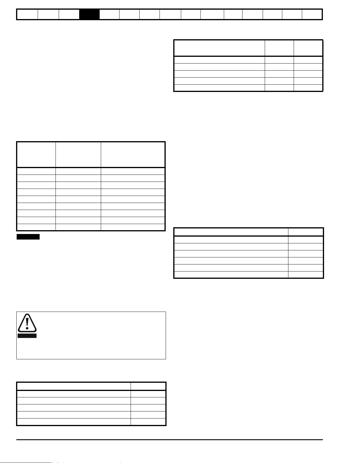
2.2.1 Maximum ratings
Table 2-1 Maximum ratings
Nominal current
I
n
AA
Model
No of input
phases
DST1201 1 1.1* 2.2
DST1202 1 2.4* 4.8
DST1203 1 2.9* 5.8
DST1204 1 4.7* 9.4
DST1201 3 1.7 5.1
DST1202 3 3.8 11.4
DST1203 3 5.4 16.2
DST1204 3 7.6 22.8
DST1401 3 1.5 4.5
DST1402 3 2.7 8.1
DST1403 3 4.0 12.0
DST1404 3 5.9 17.7
DST1405 3 8.0 24.0
*The maximum rating information, in Table 2-1 above, for the 200 V
single phase supply, illustrates a 200 % overload capability. When the
Digitax ST 120x is used with a single phase supply it is possible to
achieve the three phase nominal current rating as long as the single
phase peak current rating is observed.
The rating information shown in section 2.3 Drive model numbers on
page 9 is based on the limitations of the drive output stage only.
The ratings are based on the following operating conditions:
• Ambient temperature = 40 °C
• Altitude = 1000 m
• Not exceeding power ratings
• DC bus voltage = 565 V for DST140X
• DC bus voltage = 325 V for DST120X
The sizing tool should be used to select a drive for a profile or condition
that is not given as an example in section 13.1.2 Typical pulse duty on
page 173.
Peak current
I
MAX
8 Digitax ST User Guide
Issue: 5
Page 9

Safety
Model: Digitax ST
Frame size
Voltage rating
2:4:200V to 240V
380V to 480V
Current rating step
Variant
DST 1 2 01 B
B:
I:
P:
Z:
E:
Base
Indexer
Plus
EZMotion
EtherCAT
Model
3098-0010
2.2/5.1Apk 250ms
S/N: 3000005001
Serial
number
Rating
Please read the manual before connecting
Electric Shock Risk: Wait 10 mins
between disconnecting supply
and accessing terminals
UL file: E171230
Approvals
Approvals label
Designed in the U.K. Made in China
IND. CONTROL
EQUIPMENT
R
RoHS
Compliant
I/P 200-240V 50-60Hz 1/3ph 4.0/3.1A
O/P 0-240V 2.2/5.1Apk
Input
voltage
CT Model type
Serial
number
Single/three phase
peak output current
Output voltage
ST 1.1A M/TL 3ph
Rating label
S/N: 3000005001
Single/three
phase input
current
Frequency
LS Model
type
CUS
8
R10
Date code
N1652
Information
Product
information
Mechanical
installation
Electrical
installation
Getting
started
Basic
parameters
Running the
motor
Optimization
EtherCAT
interface
SMARTCARD
Operation
2.3 Drive model numbers
Each drive variant and rating has a unique model number.
Figure 2-1 Model code explanation
2.4 Drive nameplate description
The drive rating label provides the user with various details relating to the drive variant and rating.
Figure 2-2 Typical drive label
Onboard
PLC
Advanced
parameters
Technical
Data
Diagnostics
UL listing
information
Digitax ST User Guide 9
Issue: 5
Page 10
Safety
Solutions
Module
slot 2
cover
Solutions
Module
slot 1
cover
Buffered
encoder output
Encoder In
connection
Motor
connections
Line to
ground
varistor
screw
AC supply
48V connection
(for low voltage
DC operation)
Braking
resistor
connections
SMARTCARD
slot
Serial port
connector
Control
terminals
Relay
terminal
Keypad
connection
EMC bracket
Ground
screw
EMC bracket
Ground
screw
Status LED
Marker tag
location
*
Internal
EMC
filter
screw
Rating
label
Approvals
label
Brake
resistor slot
Reset
button
**
Fan
Control cable
strain relief
Product
identifier
NOTE
NOTE
WARNING
CAUTION
Information
Product
information
Mechanical
installation
Electrical
installation
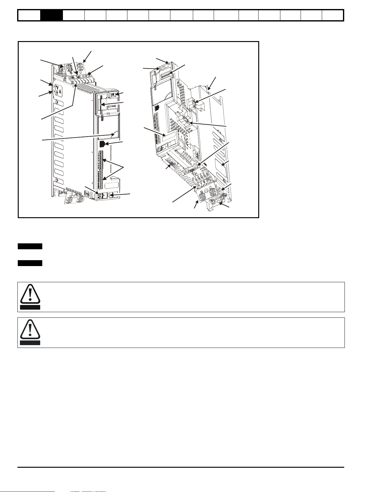
2.5 Features of the drive
Figure 2-3 Features of the drive
Getting
started
Basic
parameters
Running the
motor
Optimization
EtherCAT
interface
SMARTCARD
Operation
Onboard
PLC
Advanced
parameters
Technical
Data
Diagnostics
UL listing
information
*
The Marker Tag (as shown in Figure 2-3 above), is where markers can be placed to identify a particular drive which can prove beneficial where several Digitax
ST drives are located in the same panel.
** A drive reset can be performed even when a keypad is not installed, by pressing the recessed reset button.
If the embedded interface is removed, the warranty for the drive will be void.
The drive is supplied with a SMARTCARD installed. Do not remove until after first power-up, as defaults are stored on the SMARTCARD.
Be aware of possible live terminals when inserting the SMARTCARD.
Static precautions must be taken when removing the Solutions Module slot covers.
10 Digitax ST User Guide
Issue: 5
Page 11

Safety
SM-Keypad Plus
SMARTCARD*
DST Keypad
CT Comms
cable
External footprint/
bookcase EMC
filter
Internal
braking
resistor
Grounding
bracket
15-way
D-type
converter
I/O Expansion
Applications
Automation
Fieldbus
Feedback
S
l
o
t
2
S
l
o
t
1
*
Inputs Outputs
• Incremental encoders • Quadrature
• SinCos encoders • Frequency and direction
• SSI encoders • SSI simulated outputs
• EnDat encoders
Information
Product
information
Mechanical
installation
Electrical
installation
Getting
started
2.6 Options
Figure 2-4 Options available with Digitax ST
Basic
parameters
Running the
motor
Optimization
EtherCAT
interface
SMARTCARD
Operation
Onboard
PLC
Advanced
parameters
Technical
Data
Diagnostics
UL listing
information
* A SMARTCARD is provided as standard. For further information refer to Chapter 10 SMARTCARD Operation on page 101.
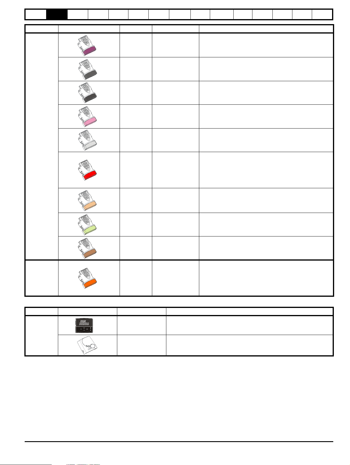
All Solutions Modules are color-coded in order to make identification easy. The following table shows the color-code key and gives further details on
their function.
Table 2-2 Solutions Module identification
Type Solutions Module Color Name Further Details
Universal Feedback interface
Feedback interface for the following devices:
SM-Universal
Encoder Plus
Resolver interface
Feedback interface for resolvers.
Simulated quadrature encoder outputs
Feedback
Light Green
Light Blue SM-Resolver
Incremental encoder interface
Brown SM-Encoder Plus
Feedback interface for incremental encoders without
commutation signals.
No simulated encoder outputs available
Digitax ST User Guide 11
Issue: 5
Page 12

Safety
• Digital inputs x 3
• Analog output (voltage) x 1
• Digital I/O x 3 • Relay x 2
• Analog inputs (voltage) x 2
Information
Product
information
Mechanical
installation
Electrical
installation
Getting
started
Basic
parameters
Running the
motor
Optimization
EtherCAT
interface
SMARTCARD
Operation
Onboard
PLC
Advanced
parameters
Type Solutions Module Color Name Further Details
Incremental encoder interface
Feedback interface for incremental encoders without
commutation signals.
Simulated encoder output for quadrature, frequency and
Dark Brown
SM-Encoder Output
Plus
direction signals
Drive encoder input converter
Provides screw terminal interface for encoder wiring and spade
terminal for shield
Single ended encoder interface
Provides an interface for single ended ABZ or UVW encoder
signals, such as those from hall effect sensors. 15 V and 24 V
versions are available.
Feedback
N/A
N/A
15-way D-type
converter
Single ended
encoder interface
(15 V or 24 V)
ERN1387 Encoder Interface Board
Provides an interface for Heidenhain ERN1387 and ERN487
SinCos encoder which use a single SinCos cycle per revolution
commutation track. A SM-Universal Encoder Plus module is
N/A
ERN1387 Encoder
Interface Board
required to use this interface board.
Extended I/O interface
Increases the I/O capability by adding the following to the
Yellow SM-I/O Plus
existing I/O in the drive:
Extended I/O interface
Increase the I/O capability by adding the following to the
Yellow SM-I/O 32
existing I/O in the drive:
• High speed digital I/O x 32
• +24 V output
Additional I/O
1 x Analog input (±10 V bi-polar or current modes)
1 x Analog output (0-10 V or current modes)
3 x Digital input and 1 x Relay
Additional I/O with real time clock
As per SM-I/O Lite but with the addition of a Real Time Clock
Automation
(I/O
Expansion)
Dark Yellow SM-I/O Lite
Dark Red SM-I/O Timer
for scheduling drive running
Isolated I/O to NAMUR NE37 specifications
For chemical industry applications
Turquoise SM-I/O PELV
1 x Analog input (current modes)
2 x Analog outputs (current modes)
4 x Digital input / outputs, 1 x Digital input, 2 x Relay outputs
Technical
Data
Diagnostics
UL listing
information
Olive SM-I/O 120V
Cobalt Blue
Automation
(Applications)
12 Digitax ST User Guide
Golden
brown
SM-I/O 24V
Protected
SM-Register
Additional I/O conforming to IEC 61131-2 120 Vac
6 digital inputs and 2 relay outputs rated for 120 Vac operation
Additional I/O with overvoltage protection up to 48 V
2 x Analog outputs (current modes)
4 x Digital input / outputs, 3 x Digital inputs, 2 x Relay outputs
Applications Processor
nd
2
processor for running position capture functionality with
CTNet support.
Issue: 5
Page 13
Safety
Information
Product
information
Mechanical
installation
Electrical
installation
Getting
started
Basic
parameters
Running the
motor
Optimization
EtherCAT
interface
SMARTCARD
Operation
Onboard
PLC
Advanced
parameters
Type Solutions Module Color Name Further Details
Technical
Data
Diagnostics
UL listing
information
Fieldbus
Purple
SM-PROFIBUS-DP-V1Profibus option
Medium Grey SM-DeviceNet
Dark Grey SM-INTERBUS
Pink SM-CAN
Light Grey SM-CANopen
Red SM-SERCOS
Beige SM-Ethernet
PROFIBUS DP adapter for communications with the drive
DeviceNet option
Devicenet adapter for communications with the drive
Interbus option
Interbus adapter for communications with the drive
CAN option
CAN adapter for communications with the drive
CANopen option
CANopen adapter for communications with the drive
SERCOS option
Class B compliant. Torque velocity and position control modes
supported with data rates (bit/sec): 2 MB, 4 MB, 8 MB and 16
MB.
Minimum 250 μsec network cycle time. Two digital high speed
probe inputs 1 μsec for position capture
Ethernet option
10 base-T / 100 base-T; Supports web pages, SMTP mail and
multiple protocols: DHCP IP addressing; Standard RJ45
connection
Pale Green SM-LON
Brown Red SM-EtherCAT
LonWorks option
LonWorks adapter for communications with the drive
EtherCAT option
EtherCAT adapter for communications with the drive
SLM interface
The SM-SLM allows SLM feedback to be connected directly to
SLM Orange SM-SLM
the Digitax ST drive and allows operation in either of the
following modes:
• Encoder only mode
• Host mode
Table 2-3 Keypad identification
Type Keypad Name Further Details
Digitax ST Keypad
LED keypad option
Keypad with a LED display
Keypad
SM-Keypad Plus
Remote keypad option
Keypad with an alpha-numeric LCD display with Help function
Digitax ST User Guide 13
Issue: 5
Page 14
Safety
Control
connectors
Relay
connector
Ground
screws
Cable
guides
Grounding
bracket
Ground
screws
Digitax ST
Plus
additional
connectors
123
Digitax ST
EtherCAT
additional
connector
Information
Product
information
Mechanical
installation
Electrical
installation
Getting
started
Basic
parameters
Running the
motor
Optimization
EtherCAT
interface
SMARTCARD
Operation
Table 2-4 Other options
Type Option Name Further details
Onboard
PLC
Advanced
parameters
Technical
Data
Diagnostics
UL listing
information
EMC EMC Filters
CT Comms cable
Communications
CTSoft
SyPTLite
These additional filters are designed to operate together with the drive’s own
integral EMC filter in areas of sensitive equipment
Cable with isolation RS232 to RS485 converter. For connecting PC/Laptop to
the drive when using the various interface software (e.g. CTSoft)
Software for PC or Laptop which allows the user to commission and store
parameter settings.
Software for PC or Laptop which allows the user to program PLC functions
within the drive.
Both CTSoft and SyPTLite can be downloaded at: http://www.emersonindustrial.com/en-EN/
controltechniques/downloads/userguidesandsoftware/Pages/digitaxst.aspx
Internal braking
resistor
SMARTCARD SMARTCARD
Braking resistor Optional braking resistor 70R 50 W
Standard feature that enables simple configuration of parameters in a variety of
ways
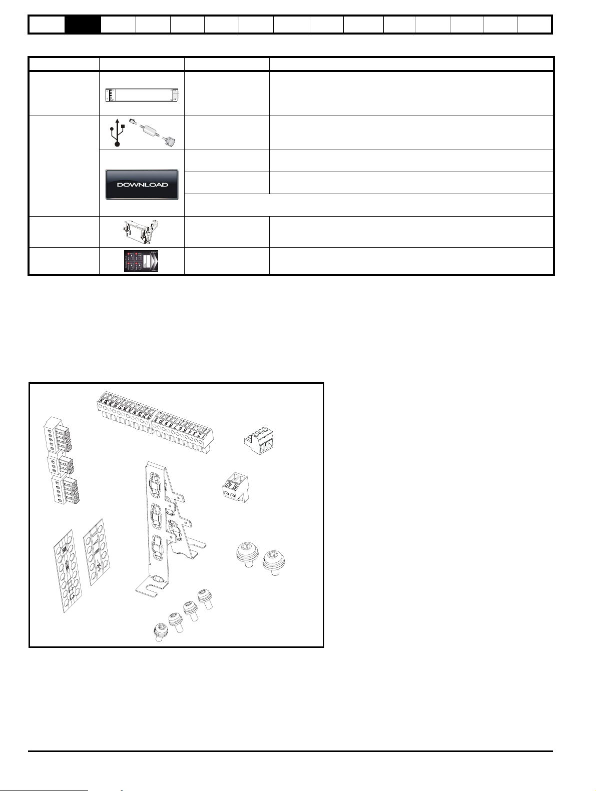
2.7 Items supplied with the drive
The drive is supplied with the following items:
• Installation Guide
•SMARTCARD
• Safety Information booklet
• Certificate of Quality
An accessory box containing the items illustrated in Figure 2-5 is also provided.
Figure 2-5 Accessory box contents
Issue: 5
14 Digitax ST User Guide
Page 15
Safety
WARNING
WARNING
WARNING
WARNING
NOTE
Drive
5
o
Information
Product
information
Mechanical
installation
Electrical
installation
Getting
started
Basic
parameters
Running the
motor
Optimization
3 Mechanical installation
This chapter describes how to use all mechanical details to install the
drive. The drive is intended to be installed in an enclosure. Key features
of this chapter include:
• Through-hole mounting
• IP54 as standard or through-panel mounting
• Enclosure sizing and layout
• Solutions Module installing
• Terminal location and torque settings
3.1 Safety information
Follow the instructions
The mechanical and electrical installation instructions must
be adhered to. Any questions or doubt should be referred to
the supplier of the equipment. It is the responsibility of the
owner or user to ensure that the installation of the drive and
any external option unit, and the way in which they are
operated and maintained, comply with the requirements of
the Health and Safety at Work Act in the United Kingdom or
applicable legislation and regulations and codes of practice in
the country in which the equipment is used.
Stored charge
The drive contains capacitors that remain charged to a
potentially lethal voltage after the AC supply has been
disconnected. If the drive has been energized, the AC
supply must be isolated at least ten minutes before work
may continue. Normally, the capacitors are discharged by an
internal resistor. Under certain, unusual fault conditions, it is
possible that the capacitors may fail to discharge, or be
prevented from being discharged by a voltage applied to the
output terminals. If the drive has failed in a manner that
causes the display to go blank immediately, it is possible the
capacitors will not be discharged. In this case, consult
Emerson Industrial Automation or their authorized
distributor.
EtherCAT
interface
SMARTCARD
Operation
Onboard
PLC
Advanced
parameters
Technical
Data
Diagnostics
UL listing
information
• corrosive gasses
During installation it is recommended that the vents on the drive are
covered to prevent debris (e.g. wire off-cuts) from entering the drive.
3.2.3 Cooling
The heat produced by the drive must be removed without its specified
operating temperature being exceeded. Note that a sealed enclosure
gives much reduced cooling compared with a ventilated one, and may
need to be larger and/or use internal air circulating fans.
3.2.4 Electrical safety
The installation must be safe under normal and fault conditions.
Electrical installation instructions are given in Chapter 4 Electrical
installation on page 21.
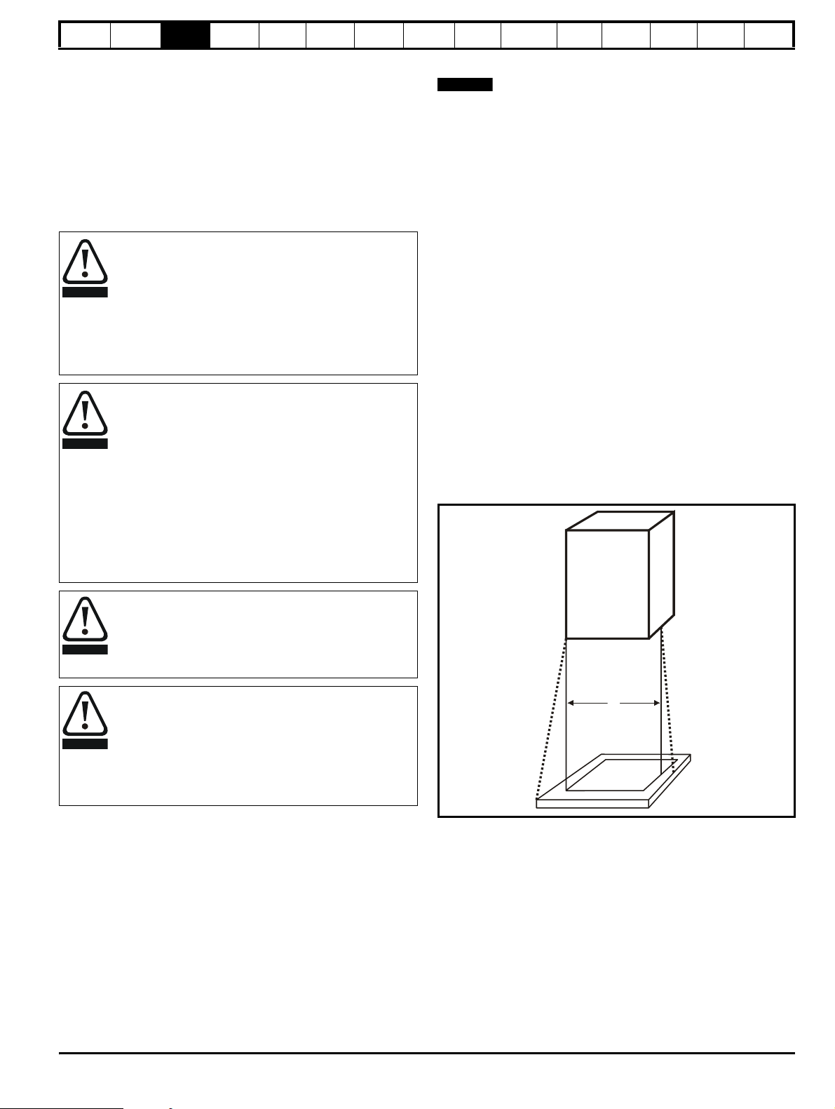
3.2.5 Fire protection
The drive enclosure is not classified as a fire enclosure. A separate fire
enclosure must be provided.
For installation in the USA, a NEMA 12 enclosure is suitable.
For installation outside the USA, the following (based on IEC 62109-1,
standard for PV inverters) is recommended.
Enclosure can be metal and/or polymeric, polymer must meet
requirements which can be summarized for larger enclosures as using
materials meeting at least UL 94 class 5VB at the point of minimum
thickness.
Air filter assemblies to be at least class V-2.
The location and size of the bottom shall cover the area shown in Figure
3-1. Any part of the side which is within the area traced out by the 5°
angle is also considered to be part of the bottom of the fire enclosure.
Figure 3-1 Fire enclosure bottom layout
Competence of the installer
The drive must be installed by professional assemblers who
are familiar with the requirements for safety and EMC. The
assembler is responsible for ensuring that the end product or
system complies with all the relevant laws in the country
where it is to be used.
Enclosure
The drive is intended to be mounted in an enclosure which
prevents access except by trained and authorized
personnel, and which prevents the ingress of contamination.
It is designed for use in an environment classified as
pollution degree 2 in accordance with IEC 60664-1. This
means that only dry, non-conducting contamination is
acceptable.
3.2 Planning the installation
The following considerations must be made when planning the installation:
3.2.1 Access
Access must be restricted to authorized personnel only. Safety
regulations which apply at the place of use must be complied with.
3.2.2 Environmental protection
The drive must be protected from:
• moisture, including dripping water or spraying water and
condensation. An anti-condensation heater may be required, which
must be switched off when the drive is running.
• contamination with electrically conductive material
• contamination with any form of dust which may restrict the fan, or
impair airflow over various components
• temperature beyond the specified operating and storage ranges
The bottom, including the part of the side considered to be part of the
bottom, must be designed to prevent escape of burning material - either
by having no openings or by having a baffle construction. This means
that openings for cables etc. must be sealed with materials meeting the
5VB requirement, or else have a baffle above. See Figure 3-2 for
acceptable baffle construction. This does not apply for mounting in an
enclosed electrical operating area (restricted access) with concrete floor.
Digitax ST User Guide 15
Issue: 5
Page 16

Safety
Notless
than 2X
Ba ffle plates (m ay be
above orbelow bottom
ofenclosure)
X
Bo ttom of fire
enclosure
Not less
than 2
times ‘X’
Baffle plates (may be above or
below bottom of enclosure)
Bottom of fire enclosure
X
CAUTION
NOTE
WARNING
Information
information
Product
Mechanical
installation
Electrical
installation
Getting
started
Basic
parameters
Running the
motor
Optimization
Figure 3-2 Fire enclosure baffle construction
3.2.6 Electromagnetic compatibility
Variable speed drives are powerful electronic circuits which can cause
electromagnetic interference if not installed correctly with careful
attention to the layout of the wiring.
Some simple routine precautions can prevent disturbance to typical
industrial control equipment.
If it is necessary to meet strict emission limits, or if it is known that
electromagnetically sensitive equipment is located nearby, then full
precautions must be observed. In-built into the drive, is an internal EMC
filter, which reduces emissions under certain conditions. If these
conditions are exceeded, then the use of an external EMC filter may be
required at the drive inputs, which must be located very close to the
drives. Space must be made available for the filters and allowance made
for carefully segregated wiring. Both levels of precautions are covered in
section 4.10 EMC (Electromagnetic compatibility) on page 28.
3.2.7 Hazardous areas
The drive must not be located in a classified hazardous area unless it is
installed in an approved enclosure and the installation is certified.
3.3 Solutions Module / keypad installation
/ removal
EtherCAT
interface
SMARTCARD
Operation
Onboard
PLC
Advanced
parameters
Figure 3-4 Installation of a keypad
Technical
Data
Diagnostics
UL listing
information
Power down the drive before installing / removing the
Solutions Module. Failure to do so may result in damage to
the product.
Figure 3-3 Installation of a Solutions Module
The protective tab from the Solutions Module slot must be removed
before attempting to install a Solutions Module.
Be aware of possible live terminals when installing the
keypad.
16 Digitax ST User Guide
Issue: 5
Page 17
Safety
WARNING
62mm
(2.44in)
249.7mm
(9.83in)
220mm (8.66in)
47mm
(1.85in)
7.5mm
(0.3in)
304mm
(11.96in)
292mm
(11.49in)
6mm
(0.24in)
∅
5.4mm (0.21in)
M5
322mm
(12.68in)
226mm (8.9in)
226mm (8.9in)
229mm (9.02in)
Ingress protective labels
NOTE
100mm (4in)
100mm (4in)
*2mm (0.08in)
NOTE
Information
Product
information
Mechanical
installation
Electrical
installation
Getting
started
Basic
parameters
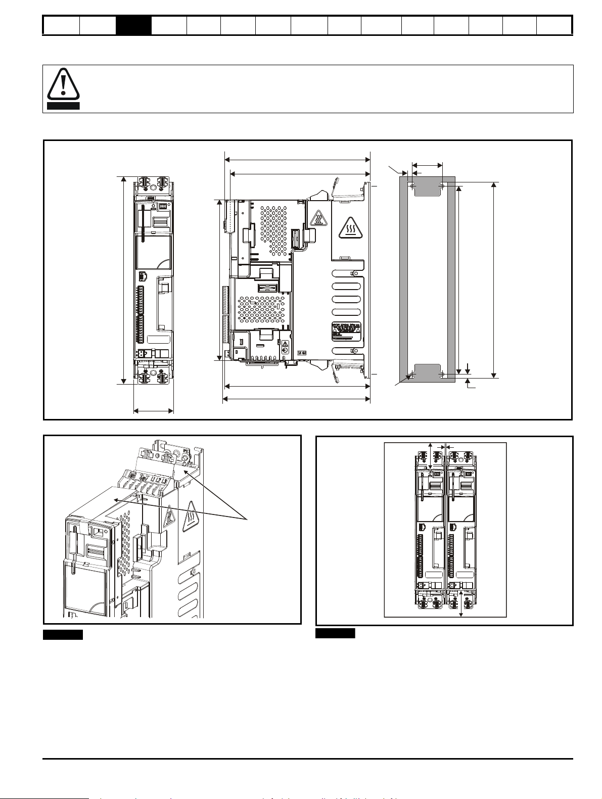
3.4 Drive dimensions
Enclosure
The drive is intended to be mounted in an enclosure which prevents access except by trained and authorized personnel, and which
prevents the ingress of contamination. It is designed for use in an environment classified as pollution degree 2 in accordance with IEC
60664-1. This means that only dry, non-conducting contamination is acceptable.
The drive complies with the requirements of IP20 as standard.
Figure 3-5 Dimensions
Running the
motor
Optimization
EtherCAT
interface
SMARTCARD
Operation
Onboard
PLC
Advanced
parameters
Technical
Data
Diagnostics
UL listing
information
Figure 3-6 Ingress protective label
The ingress protective labels (shown on Figure 3-6 above) should
remain in place while the drive is mounted, and until all the electrical
wires have been connected. The labels should be removed before first
power up.
Figure 3-7 Minimum mounting clearances
*2 mm clearance between drives to allow for mechanical tolerance.
If Solutions Modules are installed, a larger clearance between drives will
be required if access to the modules is needed without removing the
drive.
Digitax ST User Guide 17
Issue: 5
Page 18
Safety
47mm (1.85in)
312.7mm
(12.31in)
Information
information
Product
Mechanical
installation
Electrical
installation
Getting
started
Basic
parameters
Running the
motor
Optimization
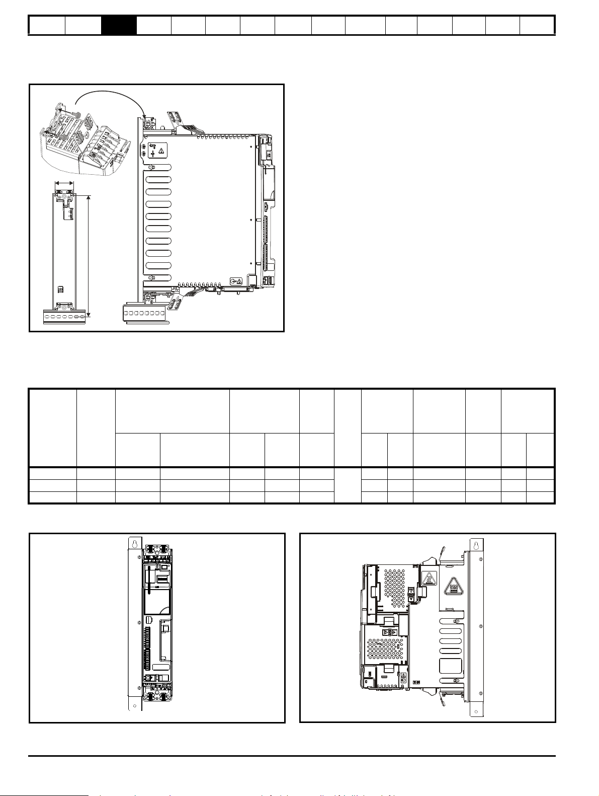
Digitax ST can be mounted using a DIN rail, either fixed at the top or the
bottom of the drive (as illustrated in Figure ). Two screws are required to
fix the drive to the backplate at the opposite end to the DIN rail.
Figure 3-8 DIN rail mounting
EtherCAT
interface
SMARTCARD
Operation
Onboard
PLC
Advanced
parameters
Technical
Data
Diagnostics
UL listing
information
3.5 External EMC filter rating
Filter details for each drive rating are provided in the tables below.
Table 3-1 External EMC filter ratings
Worst
case
leakage
current
Used with
Number
of
phases
Filter part number
CT Schaffner
Maximum
continuous
current
@40°C
(104°F)
@50°C
Power
losses
at rated
current
Weight
IP
rating
Operational
leakage
current
(122°F)AWKglbmAmANmlb ft
A
DST120X 1 4200-6000 FS23072-19-07 19 17.3 11
DST120X 3 4200-6001 FS23073-17-07 17 15.5 13 1.2 2.64 8 50 0.8 0.6
1.2 2.64 29.5 56.9 0.8 0.6
20
DST140X 3 4200-6002 FS23074-11-07 11 10 10 1.2 2.64 16 90 0.8 0.6
The external EMC filters can be footprint or bookcase mounted, see Figure 3-9 and Figure 3-10.
Figure 3-9 Bookcase mounting Figure 3-10 Footprint mounting
Filter
terminal
tightening
torque
18 Digitax ST User Guide
Issue: 5
Page 19

Safety
29mm (1.14in)
359mm (14.13in)
339mm (13.35in)
304mm (11.97in)
38mm
(1.50in)
61mm
(2.40in)
M5 M5
Torque settings of connector = 0.8 N m
∅
5.3mm (M5)
(0.21in)
∅
5.3mm (M5)
(0.21in)
4
2
1
Brake
connections
Thermistor
connection
3
5
6
WARNING
Information
Product
information
Mechanical
installation
Electrical
installation
Getting
started
Basic
parameters
Running the
motor
Optimization
EtherCAT
interface
SMARTCARD
Operation
Onboard
PLC
Advanced
parameters
Technical
Data
Diagnostics
UL listing
information
Figure 3-11 External EMC filter dimensions
Figure 3-11 shows a 3 phase filter. For a single phase filter, there are only 3 input terminals (L1, N, ground) and 3 output cables (L1, N, ground).
3.6 Optional braking resistor
3.6.1 Optional internal braking resistor
Figure 3-12 Installing an optional internal braking resistor (top view of drive)
1. Remove screws.
2. Remove grill.
3. Install the braking resistor shield.
4. Install the optional internal braking resistor in the slot provided (note the angle).
5. Electrically connect the braking resistor and thermistor (connections shown in Figure 4-1 Power terminal connections on page 22).
6. Re-install the grill and mounting screws by reversing the procedure in points 1 and 2.
3.6.2 Optional external braking resistor
If using an external braking resistor, the following Warning must be adhered to:
Digitax ST User Guide 19
Issue: 5
Braking resistor: High temperatures and overload protection
Braking resistors can reach high temperatures. Locate braking resistors so that damage cannot result. Use cable having insulation capable
of withstanding the high temperatures.
Page 20

Safety
Information
information
Product
Mechanical
installation
Electrical
installation
Getting
started
Basic
parameters
Running the
motor
3.7 Terminal torque settings
Table 3-2 Torque settings
Terminals Torque setting*
Power terminals 1.0 N m (12.1 lb in)
Control terminals 0.2 N m (1.7 lb in)
Status relay terminals 0.5 N m (4.5 lb in)
Ground terminals 4 N m (35 lb in)
Small ground terminal screws 2 N m (17.7 lb in)
*Torque tolerance = 10 %
Table 3-3 Plug-in terminal block maximum cable sizes
Model size Terminal block description Max cable size
All 11 way control connectors
All 2 way relay connector
1.5 mm
2.5 mm
2
(16 AWG)
2
(12 AWG)
3.8 Routine maintenance
The drive should be installed in a cool, clean, well ventilated location.
Contact of moisture and dust with the drive should be prevented.
Regular checks of the following should be carried out to ensure drive /
installation reliability are maximized:
Environment
Ambient
temperature
Dust
Moisture
Enclosure
Enclosure
door filters
Electrical
Screw
connections
Crimp
terminals
Cables Check all cables for signs of damage
Ensure the enclosure temperature remains at or below
maximum specified
Ensure the drive remains dust free – check that the
heatsink and drive fan are not gathering dust. The
lifetime of the fan is reduced in dusty environments.
Ensure the drive enclosure shows no signs of
condensation
Ensure filters are not blocked and that air is free to flow
Ensure all screw terminals remain tight
Ensure all crimp terminals remains tight – check for any
discoloration which could indicate overheating
Optimization
EtherCAT
interface
SMARTCARD
Operation
Onboard
PLC
Advanced
parameters
Technical
Data
Diagnostics
UL listing
information
20 Digitax ST User Guide
Issue: 5
Page 21

Safety
WARNING
WARNING
WARNING
WARNING
WARNING
WARNING
WARNING
Information
Product
information
Mechanical
installation
Electrical
installation
Getting
started
Basic
parameters
Running the
motor
Optimization
4 Electrical installation
Many cable management features have been incorporated into the
product and accessories, this chapter shows how to optimize them. Key
features include:
• Safe Torque Off function
• Internal EMC filter
• EMC compliance with shielding / grounding accessories
• Product rating, fusing and cabling information
• Brake resistor details (selection / ratings)
Electric shock risk
The voltages present in the following locations can cause
severe electric shock and may be lethal:
• AC supply cables and connections
• DC and brake cables, and connections
• Output cables and connections
• Many internal parts of the drive, and external option units
Unless otherwise indicated, control terminals are single
insulated and must not be touched.
Isolation device
The AC supply must be disconnected from the drive using
an approved isolation device before any cover is removed
from the drive or before any servicing work is performed.
EtherCAT
interface
SMARTCARD
Operation
Onboard
PLC
Advanced
parameters
Technical
Data
Diagnostics
UL listing
information
STOP function
The STOP function does not remove dangerous voltages
from the drive, the motor or any external option units.
Safe Torque Off function
The Safe Torque Off function does not remove dangerous
voltages from the drive, the motor or any external option
units.
Stored charge
The drive contains capacitors that remain charged to a
potentially lethal voltage after the AC supply has been
disconnected. If the drive has been energized, the AC
supply must be isolated at least ten minutes before work
may continue.
Normally, the capacitors are discharged by an internal
resistor. Under certain, unusual fault conditions, it is possible
that the capacitors may fail to discharge, or be prevented
from being discharged by a voltage applied to the output
terminals. If the drive has failed in a manner that causes the
display to go blank immediately, it is possible the capacitors
will not be discharged. In this case, consult Emerson
Industrial Automation or their authorized distributor.
Equipment supplied by plug and socket
Special attention must be given if the drive is installed in
equipment which is connected to the AC supply by a plug
and socket. The AC supply terminals of the drive are
connected to the internal capacitors through rectifier diodes
which are not intended to give safety isolation. If the plug
terminals can be touched when the plug is disconnected
from the socket, a means of automatically isolating the plug
from the drive must be used (e.g. a latching relay).
Permanent magnet motors
Permanent magnet motors generate electrical power if they
are rotated, even when the supply to the drive is
disconnected. If that happens then the drive will become
energized through its motor terminals.
If the motor load is capable of rotating the motor when the
supply is disconnected, then the motor must be isolated from
the drive before gaining access to any live parts.
Digitax ST User Guide 21
Issue: 5
Page 22
Safety
L1*L2
*
L2L1L3/N
UVW
Optional EMC
filter
Optional
line reactor
Fuses
L3
*
Mains
supply
Supply
ground
AC
connections
_
+
DC
DC
High current
-DC connections
+
_
Low voltage
DC (48V)
DST12XX = 200 to 240V 10%
DST14XX = 380 to 480V 10%
±
±
Connectors specification:
Maximum size of power cable
= 4.0mm (10AWG)
Torque setting = 1 N m
2
PE
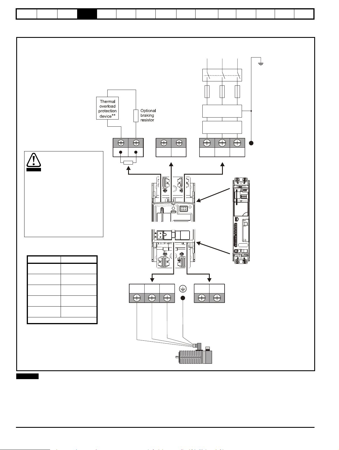
It is essential that the braking
resistor be protected against
overload caused by a failure
of the brake control. Unless
the resistor has in-built
protection, a circuit like those
shown in Figure 4-1 should
be used, where the thermal
protection device
disconnects the AC supply to
the drive. Do not use AC
relay contacts directly in
series with the braking
resistor circuit, because it
carries DC.
WARNING
Terminals Torque setting
Power terminals
1.0 N m
(12.1 lb in)
Control terminals
0.2 N m
(1.7 lb in)
Status relay
terminals
0.5 N m
(4.5 lb in)
Ground terminal
screws
4 N m
(35 lb in)
Small ground
terminal screws
2 Nm
(17.7 Ib in)
* *Torque tolerance = 10%
NOTE
Information
Product
information
Mechanical
installation
Electrical
installation
Getting
started
4.1 Power terminal connections
Figure 4-1 Power terminal connections
Basic
parameters
Running the
motor
Optimization
EtherCAT
interface
SMARTCARD
Operation
Onboard
PLC
Advanced
parameters
Technical
Data
Diagnostics
UL listing
information
* When using a 200 V drive on a single phase supply, the live and neutral conductors can be connected to any of the AC connections on the drive.
** This is not required if the optional internal braking resistor is used.
22 Digitax ST User Guide
Issue: 5
Page 23

Safety
WARNING
WARNING
Supply
ground
Motor
ground
WARNING
L
Y
100
----------
V
3
-------
×
1
2π f I
------------
×=
Information
Product
information
Mechanical
installation
Electrical
installation
Getting
started
Basic
parameters
Running the
motor
Optimization
EtherCAT
interface
SMARTCARD
Operation
Onboard
PLC
Advanced
parameters
Technical
Data
Diagnostics
UL listing
information
4.2 Ground connections
Electrochemical corrosion of grounding terminals
Ensure that grounding terminals are protected against
corrosion i.e. as could be caused by condensation.
The drive must be connected to the system ground of the AC supply. The
ground wiring must conform to local regulations and codes of practice.
The supply and motor ground connections are made using the M6
threaded hole in the metal back plate of the drive located at the top and
bottom of the drive. See Figure 4-2 for details.
The ground loop impedance must conform to the
requirements of local safety regulations.
The drive must be grounded by a connection capable of
carrying the prospective fault current until the protective
device (fuse, etc.) disconnects the AC supply.
The ground connections must be inspected and tested at
appropriate intervals.
Figure 4-2 Ground connection
4.3 AC supply requirements
Table 4-1 Supply requirements
Model Voltage
DST120X 200 V to 240 V ±10 % single phase 48 Hz to 65 Hz
DST120X 200 V to 240 V ±10 % three phase* 48 Hz to 65 Hz
DST140X 380 V to 480 V ±10 % three phase* 48 Hz to 65 Hz
*Maximum supply in-balance: 2 % negative phase sequence (equivalent
to 3 % voltage in-balance between phases).
For UL compliance only, the maximum supply symmetrical fault current
must be limited to 100 kA.
4.3.1 Supply types
All drives are suitable for use on any supply type i.e TN-S, TN-C-S, TT
and IT.
• Supplies with voltage up to 600 V may have grounding at any
potential, i.e. neutral, centre or corner (“grounded delta”)
• Supplies with voltage above 600 V may not have corner grounding
Drives are suitable for use on supplies of installation category III and
lower, according to IEC60664-1. This means they may be connected
permanently to the supply at its origin in a building, but for outdoor
installation additional over-voltage suppression (transient voltage surge
suppression) must be provided to reduce category IV to category III.
Frequency
range
Operation with IT (ungrounded) supplies:
Special attention is required when using internal or external
EMC filters with ungrounded supplies, because in the event
of a ground (earth) fault in the motor circuit the drive may not
trip and the filter could be over-stressed. In this case, either
the filter must not be used (removed) or additional
independent motor ground fault protection must be provided.
Refer to Table 4-2.
For instructions on removal, refer to Figure 4-4 Removing
the internal EMC filter and line to ground varistors on
page 28. For details of ground fault protection contact the
supplier of the drive.
A ground fault in the supply has no effect in any case. If the motor must
continue to run with a ground fault in its own circuit then an input
isolating transformer must be provided and if an EMC filter is required it
must be located in the primary circuit.
Unusual hazards can occur on ungrounded supplies with more than one
source, for example on ships. Contact the supplier of the drive for more
information.
Table 4-2 Behavior of the drive in the event of a motor circuit
ground (earth) fault with an IT supply
Drive size Internal filter only External filter (with internal)
0 (200 V)
May not trip – precautions
required
Drive trips on fault
0 (400 V) Drive trips on fault Drive trips on fault
4.3.2 Line reactors
Input line reactors reduce the risk of damage to the drive resulting from
poor phase balance or severe disturbances on the supply network.
Where line reactors are to be used, reactance values of approximately 2
% are recommended. Higher values may be used if necessary, but may
result in a loss of drive output (reduced torque at high speed) because of
the voltage drop.
For all drive ratings, 2 % line reactors permit drives to be used with a
supply imbalance of up to 3.5 % negative phase sequence (equivalent to
5 % voltage imbalance between phases).
Severe disturbances may be caused by the following factors, for
example:
• Power factor correction equipment connected close to the drive
• Large DC drives having no or inadequate line reactors connected to
the supply
• Direct-on-line started motor(s) connected to the supply such that
when any of these motors are started, the voltage dip exceeds 20 %
Such disturbances may cause excessive peak currents to flow in the
input power circuit of the drive. This may cause nuisance tripping, or in
extreme cases, failure of the drive.
Drives of low power rating may also be susceptible to disturbance when
connected to supplies with a high rated capacity.
When required, each drive must have its own reactor(s). Three individual
reactors or a single three-phase reactor should be used.
Reactor current ratings
Continuous current:
Not less than the continuous input current rating of the drive.
Repetitive peak current:
Not less than three times the continuous input current rating of the drive.
4.3.3 Input inductor calculation
To calculate the inductance required (at Y%), use the following equation:
Where:
I = drive rated input current (A)
L = inductance (H)
f = supply frequency (Hz)
V = voltage between lines
Digitax ST User Guide 23
Issue: 5
Page 24
Safety
NOTE
WARNING
Information
Product
information
Mechanical
installation
Electrical
installation
Getting
started
Basic
parameters
Running the
motor
Optimization
EtherCAT
interface
SMARTCARD
Operation
Onboard
PLC
Advanced
parameters
Technical
Data
Diagnostics
UL listing
information
4.4 DC bus design
4.4.1 DC bus design
Parallel connections
The power limit of the rectifier must be adhered to for all combinations of
drives in parallel. In addition to this If the total rated bus power required
exceeds the capability of 1 x Digitax ST rectifier then two or more Digitax
ST's can be connected with the AC & DC in parallel. If the AC supply is
connected to more than one drive in a parallel DC bus application,
balancing of the current in the input stage of each drive must be
considered.
Using DC bus chokes makes the current in the rectifier diodes of each
drive the same, so providing a solution to sharing.
There are many possible combinations for paralleling drives through the
DC bus connections. Table 4-3 gives details of the internal capacitance
for each drive and the additional capacitance which can be powered
from the drive. The capacitance must incorporate its own soft-start
circuit. All Digitax ST drives incorporate this feature.
Table 4-3 DC bus data
Internal DC bus
Drive
capacitance
(μF)
DST1201 440 1760
DST1202 880 1320
DST1203 880 1320
DST1204 1320 880
DST1401 220 660
DST1402 220 660
DST1403 220 660
DST1404 220 660
DST1405 220 660
For additional details regarding DC bus paralleling please contact the
supplier of the drive.
Maximum additional DC
bus capacitance which can
be connected
(μF)
4.5 DC drive voltage levels
4.5.1 Low voltage DC operation
The drive can be operated from low voltage DC supplies, nominally 24
Vdc (control) and 48 Vdc (power). The low voltage DC power operating
mode is designed either, to allow for motor operation in an emergency
back-up situation following failure of the AC supply, for example in
robotic arm applications; or to limit the speed of a servo motor during
set-up of equipment, for example a robot cell.
With low voltage DC operation there is a reduction in the
level of safety of the Safe Torque Off function. There
exist certain unlikely faults which might permit the drive to
produce some limited motor torque, if the DC supply has its
negative terminal connected to ground.
See section 4.17 Safe Torque Off on page 42 for methods
on preventing a loss of the safety function under these
conditions.
The working voltage range of the low voltage DC power supply is shown
in Table 4-4.
Table 4-4 Low voltage DC levels
Condition Value
Minimum continuous operating voltage 36 V
Minimum start up voltage 40 V
Nominal continuous operating voltage 48 V to 72 V
Maximum braking IGBT turn on voltage 63 V to 95 V
Maximum over voltage trip threshold 69 V to 104 V
4.5.2 High voltage DC levels
Table 4-5 High voltage DC levels
Condition
DST120X DST140X
VV
Undervoltage trip level 175 330
Undervoltage reset level* 215 425
Overvoltage trip level 415 830
Braking level 390 780
Maximum continuous voltage level for 15 s 400 800
* These are the absolute minimum DC voltages that the drive is capable
of operating from. If the drive is not supplied with the minimum voltage, it
will not reset following a UV trip at power-up.
4.5.3 Control 24 Vdc supply
The 24 Vdc input has three main functions:
• It can be used as a back-up power supply to keep the control circuits
of the drive powered up when the line power supply is removed. This
allows any fieldbus modules or serial communications to continue to
operate.
• It can be used to supplement the drive’s own internal 24 V when
multiple SM-I/O Plus modules are being used and the current drawn
by these modules is greater than the drive can supply. (If too much
current is drawn from the drive, the drive will initiate a 'PS.24V' trip)
• It can be used to commission the drive when line power supply
voltages are not available, as the display operates correctly.
However, the drive will be in the UV trip state unless either line
power supply is reapplied or low voltage DC operation is enabled,
therefore diagnostics may not be possible. (Power down save
parameters are not saved when using the 24 V back-up power
supply input.)
The working voltage range of the 24 V power supply is shown in Table 4-6.
Table 4-6 Control supply voltage levels
Condition Value
Maximum continuous operating voltage 30.0 V
Minimum continuous operating voltage 19.2 V
Nominal operating voltage 24.0 V
Minimum start up voltage 21.6 V
Maximum power supply requirement at 24 V 60 W
Recommended fuse 3 A, 50 Vdc
Minimum and maximum voltage values include ripple and noise. Ripple
and noise values must not exceed 5 %.
24 Digitax ST User Guide
Issue: 5
Page 25
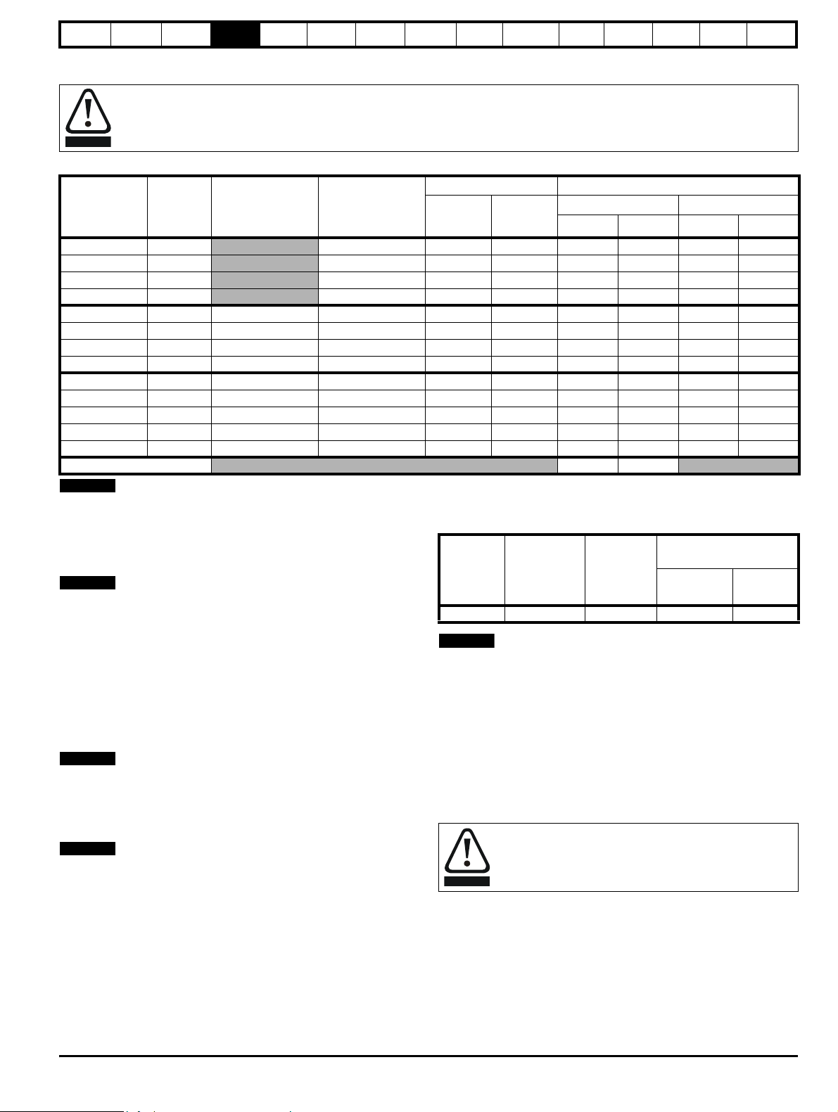
Safety
WARNING
NOTE
NOTE
NOTE
NOTE
NOTE
WARNING
Information
Product
information
Mechanical
installation
Electrical
installation
Getting
started
Basic
parameters
Running the
motor
Optimization
EtherCAT
interface
SMARTCARD
Operation
Onboard
PLC
Advanced
parameters
Technical
Data
Diagnostics
4.6 Ratings
Fuses
The AC supply to the drive must be installed with suitable protection against overload and short-circuits. The following section shows
recommended fuse ratings. Failure to observe this requirement will cause risk of fire.
Table 4-7 Fuse ratings and cable sizes
No of
Model
input
phases
DST1201 1
DST1202 1
DST1203 1
DST1204 1
Typical input
current
A
Maximum
continuous input
current
A
4.0 6 10 0.75 16 0.75 24
7.6 10 10 1 16 0.75 22
9.0 16 15 2.5 14 0.75 20
13.4 16 20 2.5 12 0.75 18
DST1201 3 3.1 3.5 6 10 0.75 16 0.75 24
DST1202 3 6.4 7.3 10 10 1 16 0.75 22
DST1203 3 8.6 9.4 16 15 2.5 14 0.75 20
DST1204 3 11.8 13.4 16 20 2.5 12 0.75 18
DST1401 3 2.6 2.8 4 10 0.75 16 0.75 24
DST1402 3 4.2 4.3 6 10 0.75 16 0.75 24
DST1403 3 5.9 6.0 8 10 0.75 16 0.75 22
DST1404 3 7.9 8.0 10 10 1 16 0.75 20
DST1405 3 9.9 9.9 12 15 1.5 14 0.75 18
Control cable
Fuse rating Cable size
IEC class
gG
Class CC
Input Output
2
mm
AWG
≥0.5 20
mm
2
UL listing
information
AWG
PVC insulated cable should be used.
Installation class (ref: IEC60364-5-52:2001)
B1 - Separate cables in conduit.
B2 - Multicore cable in conduit
C - Multicore cable in free air.
Cable sizes are from IEC60364-5-52:2001 table A.52.C with correction
factor for 40°C ambient of 0.87 (from table A52.14) for cable installation
method B2 (multicore cable in conduit).
Cable size may be reduced if a different installation method is used, or if
the ambient temperature is lower.
The recommended cable sizes above are only a guide. The mounting
and grouping of cables affects their current-carrying capacity, in some
cases smaller cables may be acceptable but in other cases a larger
cable is required to avoid excessive temperature or voltage drop. Refer
to local wiring regulations for the correct size of cables.
N
The recommended output cable sizes assume that the motor maximum
current matches that of the drive. Where a motor of reduced rating is
used the cable rating may be chosen to match that of the motor. To
ensure that the motor and cable are protected against overload, the
drive must be programmed with the correct motor rated current.
N
UL listing is dependent on the use of the correct type of UL-listed fuse,
and applies when symmetrical short-circuit current does not exceed
100kA. See Chapter 15 UL listing information on page 204 for sizing
information.
An MCB (miniature circuit breaker) may be used in place of fuses under
the following conditions:
• The fault-clearing capacity must be sufficient for the installation
• The I2T rating of the MCB must be less than or equal to that of the fuse
rating listed above.
A fuse or other protection must be included in all live connections to the
AC supply.
For a parallel DC bus system the maximum AC input fusing is shown in
Table 4-8 below.
Table 4-8 Maximum AC input fusing
Fuse rating
IEC class gG
Fuse rating
class CC
Input cable size
Model
AA
mm
2
AWG
All 20 20 4.0 12
Refer to the supplier of your drive for further information regarding DC
bus paralleling.
4.7 Output circuit and motor protection
The output circuit has fast-acting electronic short-circuit protection which
limits the fault current to typically no more than five times the rated
output current, and interrupts the current in approximately 20 µs. No
additional short-circuit protection devices are required.
The drive provides overload protection for the motor and its cable. For
this to be effective, Pr 0.46 Motor rated current must be set to suit the
motor.
Pr 0.46 Motor rated current must be set correctly to avoid a
risk of fire in the event of motor overload.
There is also provision for the use of a motor thermistor to prevent overheating of the motor, e.g. due to loss of cooling.
4.7.1 Motor cable size and maximum lengths
Since capacitance in the motor cable causes loading on the output of the
drive, ensure the cable length does not exceed the values given in Table
4-9.
Use 105 °C (221 °F) (UL 60/75 °C temp rise) PVC-insulated cable with
copper conductors having a suitable voltage rating, for the following
power connections:
Digitax ST User Guide 25
Issue: 5
Page 26
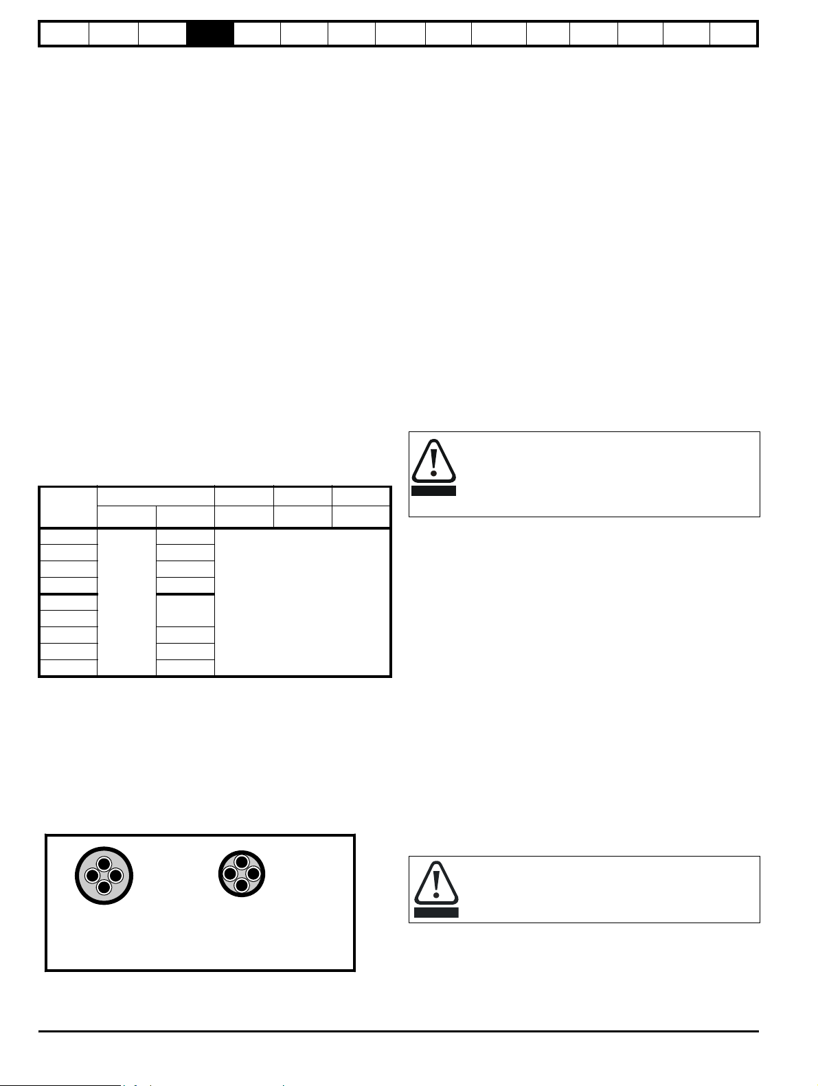
Safety
Normal capacitance
Shield or armour
separated from the cores
High capacitance
Shield or armour close
to the cores
WARNING
CAUTION
Information
Product
information
Mechanical
installation
Electrical
installation
Getting
started
Basic
parameters
Running the
motor
Optimization
EtherCAT
interface
SMARTCARD
Operation
Onboard
PLC
Advanced
parameters
Technical
Data
Diagnostics
UL listing
information
• AC supply to external EMC filter (when used)
• AC supply (or external EMC filter) to drive
• Drive to motor
• Drive to braking resistor
•
When operating in ambient >45 °C UL 75 °C cable should be used.
Cable sizes are given for guidance only and may be changed depending
on the application and the method of installation of the cables.
The mounting and grouping of cables affect their current capacity, in
some cases a larger cable is required to avoid excessive temperature or
voltage drop.
Input cable sizes should generally be regarded as a minimum, since
they have been selected for co-ordination with the recommended fuses.
Output cable sizes assume that the maximum motor current matches
that of the drive.
Where a motor of reduced rating is used the cable rating may be chosen
to match that of the motor.
To ensure that the motor and cable are protected against overload, the
drive must be programmed with the correct motor rated current.
• Cable lengths in excess of the specified values may be used only
when special techniques are adopted; refer to the supplier of the
drive.
• The default switching frequency is 6 kHz.
The drive power terminals are designed for a maximum cable size of 4.0
2
mm
(minimum 0.2 mm / 24 AWG).
Where more than one cable per terminal is used the combined
diameters should not exceed the maximum.
The terminals are suitable for both solid and stranded wires.
Table 4-9 Motor cable size and maximum lengths
Output cable 6kHz 8kHz 12kHz
Model
DST1201
mm
2
AWG m m m
24
DST1202 22
DST1203 20
DST1204 18
DST1401
DST1402
0.75
24
50
DST1403 22
DST1404 20
DST1405 18
High-capacitance cables
The maximum cable length is reduced from that shown in Table 4-9 if
high capacitance motor cables are used.
Most cables have an insulating jacket between the cores and the armor
or shield; these cables have a low capacitance and are recommended.
Cables that do not have an insulating jacket tend to have high
capacitance; if a cable of this type is used, the maximum cable length is
half that quoted in the tables. (Figure 4-3 shows how to identify the two
types).
Figure 4-3 Cable construction influencing the capacitance
4.7.2 Motor winding voltage
The PWM output voltage can adversely affect the inter-turn insulation in
the motor. This is because of the high rate of change of voltage, in
conjunction with the impedance of the motor cable and the distributed
nature of the motor winding.
For normal operation with AC supplies up to 500 Vac and a standard
motor with a good quality insulation system, there is no need for any
special precautions. In case of doubt the motor supplier should be
consulted.
Special precautions are recommended under the following conditions,
but only if the motor cable length exceeds 10 m:
• AC supply voltage exceeds 500 V
• DC supply voltage exceeds 670 V
• Operation of 400 V drive with continuous or very frequent sustained
braking
For the other cases listed, it is recommended that an inverter-rated
motor be used. This has a reinforced insulation system intended by the
manufacturer for repetitive fast-rising pulsed voltage operation.
If it is not practical to use an inverter-rated motor, an output choke
(inductor) should be used. The recommended type is a simple iron-cored
component with a reactance of about 2 %. The exact value is not critical.
This operates in conjunction with the capacitance of the motor cable to
increase the rise-time of the motor terminal voltage and prevent
excessive electrical stress.
4.7.3 Output contactor
If the cable between the drive and the motor is to be
interrupted by a contactor or circuit breaker, ensure that the
drive is disabled before the contactor or circuit breaker is
opened or closed. Severe arcing may occur if this circuit is
interrupted with the motor running at high current and low
speed.
A contactor is sometimes required to be installed between the drive and
motor for safety purposes.
The recommended motor contactor is the AC3 type.
Switching of an output contactor should only occur when the output of
the drive is disabled.
Opening or closing of the contactor with the drive enabled will lead to:
1. OI.AC trips (which cannot be reset for 10 seconds)
2. High levels of radio frequency noise emission
3. Increased contactor wear and tear
The Drive Enable terminal (T31) when opened provides a Safe Torque
Off function. This can in many cases replace output contactors.
For further information see section 4.17 Safe Torque Off on page 42.
4.8 Braking
The internal braking resistor can be used with the drive even though its
resistance is lower than the minimum resistance values given in
Table 4-11, because of the following reasons.
• The braking resistor overload protection function in the drive is set
up to limit the power dissipated in the resistor.
• The braking resistor is installed with a thermistor which will trip the
drive if the resistor is too hot.
• The power rating of the resistor is only 50 W
The internal braking resistor for Digitax ST is installed with a
thermistor which must be connected to the drive whenever
the internal braking resistor in installed.
If an external resistor is used with the drive, its resistance must be equal
to or greater than the value given in Table 4-11.
The cable used for Table 4-9 is shielded and contains four cores. Typical
capacitance for this type of cable is 130 pF/m (i.e. from one core to all
others and the shield connected together).
26 Digitax ST User Guide
Issue: 5
Page 27
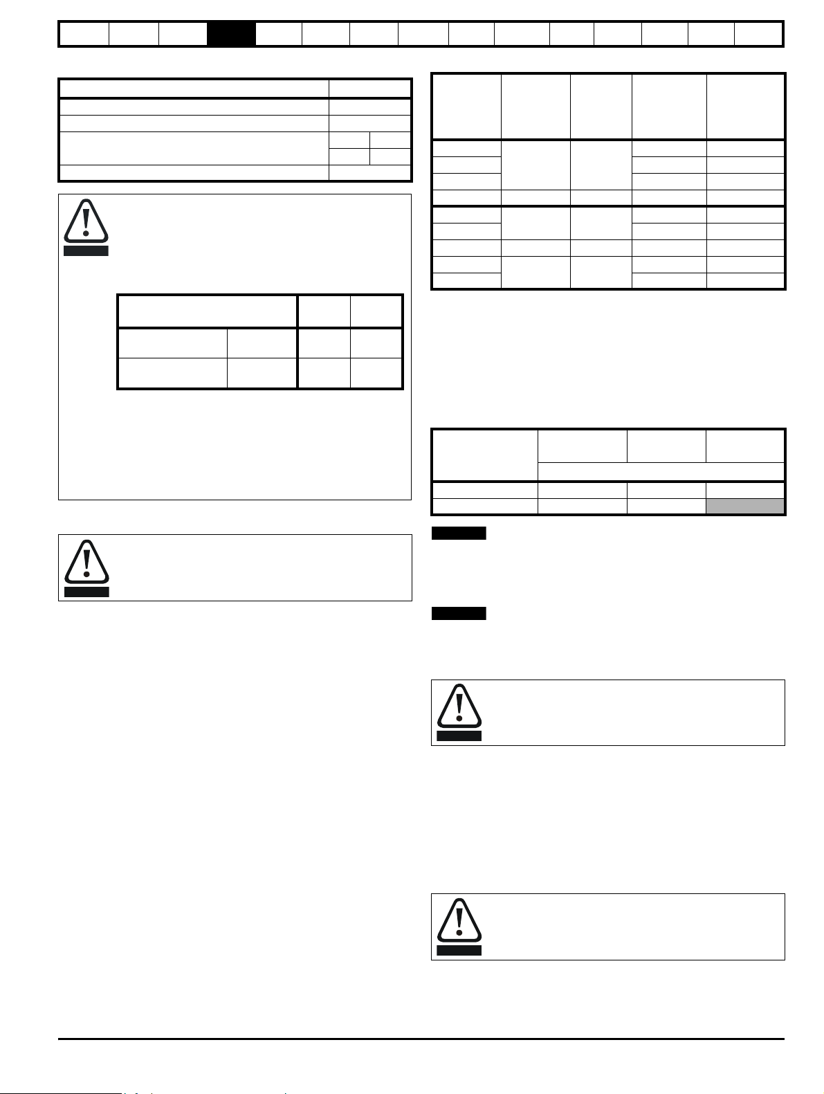
Safety
CAUTION
Parameter
200 V
drive
400 V
drive
Full power braking
time
Pr 10.30 0.06 0.01
Full power braking
period
Pr 10.31 2.6 1.7
WARNING
NOTE
NOTE
WARNING
WARNING
Information
Product
information
Mechanical
installation
Electrical
installation
Getting
started
Basic
parameters
Running the
motor
Optimization
EtherCAT
interface
SMARTCARD
Operation
Onboard
PLC
Advanced
parameters
Technical
Data
Diagnostics
UL listing
information
Table 4-10 Internal braking resistor data
Parameter
Part number 1299-0001
DC resistance at 25 °C 70 Ω
Peak instantaneous power over 1ms at nominal
resistance
200 V 400 V
2.2 kW 8.7 kW
Average power over 60 s 50 W
Braking resistor overload protection parameter settings
Failure to observe the following information may
damage the resistor.
The drive’s software contains an overload protection
function for a braking resistor. On Digitax ST this function is
enabled at default to protect the internally mounted resistor.
Below are the parameter settings.
For more information on the braking resistor software
overload protection, see Pr 10.30 and Pr 10.31 full
descriptions in the Advanced User Guide.
If the internally mounted braking resistor is to be used at
more than half of its average power rating then the drive's
cooling fan must be at full speed, controlled by setting
Pr 6.45 to On (1).
4.8.1 External braking resistor
Overload protection
When an external braking resistor is used, it is essential that
an overload protection device is incorporated in the braking
resistor circuit.
When a braking resistor is to be mounted outside the enclosure, ensure
that it is mounted in a ventilated metal housing that will perform the
following functions:
• Prevent inadvertent contact with the resistor
• Allow adequate ventilation for the resistor
When compliance with EMC emission standards is required, external
connection requires the cable to be armored or shielded, since it is not
fully contained in a metal enclosure. See section 4.10 EMC
(Electromagnetic compatibility) on page 28 for further details.
Internal connection does not require the cable to be armored or
shielded.
Table 4-11 Minimum resistance and power ratings
Average
power for
0.25s
Model
Minimum
resistance*
Peak
power
rating
Continuous
power rating
Ω kW kW kW
DST1201
DST1202 1.2 3.5
23 6.6
0.5 1.6
DST1203 1.6 4.9
DST1204 16 9.3 2.3 7.0
DST1401
DST1402 1.4 4.1
111 5.5
0.8 2.3
DST1403 75 8.1 2.0 6.1
DST1404
DST1405 4.1 12.2
28 21.7
3.0 9.0
* Resistor tolerance: ±10 %
4.9 Ground leakage
The ground leakage current depends upon whether the internal EMC
filter is installed. The drive is supplied with the filter installed. Instructions
for removing the internal filter are given in Figure 4-4.
With the internal EMC filter installed the ground leakage current is as
follows:
Table 4-12 Ground leakage current with internal EMC filter installed
3 phase Star
Model
ground
DST120X at 220 V 4 10 3
DST140X at 400 V 12 40
The above leakage current is just the leakage current of the drive with the
internal EMC filter connected and does not take into account any leakage
currents of the motor or motor cable.
With internal EMC filter removed the ground leakage current = <1 mA.
In both cases, there is an internal voltage surge suppression device
connected to ground. Under normal circumstances, this carries
negligible current.
When the internal EMC filter is installed, the leakage current
is high. In this case, a permanent fixed ground connection
must be provided with a cross sectional area equal to 10mm
4.9.1 Use of residual current device (RCD)
There are three common types of ELCB / RCD:
1. AC - detects AC fault currents
2. A - detects AC and pulsating DC fault currents (provided the DC
current reaches zero at least once every half cycle)
3. B - detects AC, pulsating DC and smooth DC fault currents
• Type AC should never be used with drives
• Type A can only be used with single phase drives
• Type B must be used with three phase drives
3 phase Delta
ground
mA
1 phase
2
.
Digitax ST User Guide 27
Issue: 5
Only type B ELCB / RCD are suitable for use with 3 phase
inverter drives.
If an external EMC filter is used, a delay of at least 50ms should be
incorporated to ensure spurious trips are not seen. The leakage current
is likely to exceed the trip level if all of the phases are not energized
simultaneously.
Page 28

Safety
WARNING
1
2
NOTE
NOTE
Information
Product
information
Mechanical
installation
Electrical
installation
Getting
started
Basic
parameters
Running the
motor
Optimization
4.10 EMC (Electromagnetic compatibility)
4.10.1 Internal EMC filter
It is recommended that the internal EMC filter is kept in place unless
there is a specific reason for removing it.
Special attention is required when using a DST120X model on an
ungrounded supply (IT supply). In the event of a ground fault in the
motor circuit the drive may not trip and the filter could be overstressed.
In this case, either the filter must be removed or additional independent
motor ground fault protection must be provided.
The internal EMC filter reduces radio-frequency emissions into the line
power supply. Where the motor cable is short, it permits the
requirements of EN 61800-3:2004 to be met for the second environment.
For longer motor cables, the filter continues to provide a useful reduction
in emission level, and when used with any length of shielded cable up to
the limit for the drive, it is unlikely that nearby industrial equipment will be
disturbed. It is recommended that the filter be used in all applications
unless the ground leakage current is unacceptable or the above
conditions are true.
The supply must be disconnected before removing the
internal EMC filter or line to ground varistor screws.
EtherCAT
interface
SMARTCARD
Operation
Onboard
PLC
Advanced
parameters
Technical
Data
Diagnostics
UL listing
information
Figure 4-4 Removing the internal EMC filter and line to ground
varistors
1. Internal EMC filter. Remove the bottom screw as shown.
2. Line to ground varistors. Remove the top screw as shown.
The line to ground varistors should only be removed in special
circumstances.
4.10.2 Further EMC precautions
Further EMC precautions are required if more stringent EMC emission
requirements apply:
• Operation in the first environment of EN 61800-3:2004
• Conformity to the generic emission standards
• Equipment which is sensitive to electrical interference operating
nearby
In this case it is necessary to use:
• The optional external EMC filter
• A shielded motor cable, with shield clamped to the grounded metal
panel
• A shielded control cable, with shield clamped to the grounded metal
panel via the grounding bracket.
It is not necessary to remove the external EMC filter when using an IT
supply.
28 Digitax ST User Guide
Issue: 5
Page 29

Safety
Metal back
plate
External
controller
Signal cables
Plan for all signal cables
to be routed at least
300mm (12in) from the
drive and any power cable
Optional
braking resistor
Locate optional braking
resistor and overload
external to cubicle
(preferably near to or
on top of the cubicle).
Note
For EMC compliance:
1) When using an external EMC
filter, one filter is required for
each drive
2) Ensure direct metal contact
at drive and filter mounting
points (any paint must be
removed)
The external EMC filter can be
bookcase mounted (next to the
drive) or footprint mounted (with
the drive mounted onto the filter).
Thermal
overload
protection
device
AC supply
contactor and
fuses or MCB
Information
Product
information
Mechanical
installation
Electrical
installation
Getting
started
Basic
parameters
4.10.3 Recommended cable management
Figure 4-5 Drive cable clearances
Running the
motor
Optimization
EtherCAT
interface
SMARTCARD
Operation
Onboard
PLC
Advanced
parameters
Technical
Data
Diagnostics
UL listing
information
Digitax ST User Guide 29
Issue: 5
Page 30

Safety
1
NOTE
NOTE
Information
Product
information
Mechanical
installation
Electrical
installation
Getting
started
Basic
parameters
Running the
motor
Optimization
EtherCAT
interface
SMARTCARD
Operation
Onboard
PLC
Advanced
parameters
Technical
Data
Diagnostics
UL listing
information
Figure 4-6 Grounding bracket at the top of the drive
Figure 4-7 Grounding bracket at the bottom of the drive
Grounding bracket and drive to be directly connected to a grounded
backplate.
1. The distance for EMC (shown in Figure 4-7 above) from the drive is as
follows:
200 V drive - Allowance up to 65 mm (2.56 in)
400 V drive - Allowance up to 100 mm (3.94 in)
The grounding bracket can remain mounted when the drive is removed.
as follows.
Figure 4-8 Multiple drives with single grounding bracket
If installing multiple drives, one grounding bracket can be used for two
drives.
4.11 Internal and external conducted emissions conformity
Table 4-13 Immunity compliance
Standard
IEC61000-4-2
EN61000-4-2
IEC61000-4-3
EN61000-4-3
IEC61000-4-4
EN61000-4-4
IEC61000-4-5
EN61000-4-5
IEC61000-4-6
EN61000-4-6
IEC61000-4-11
EN61000-4-11
IEC61000-6-1
EN61000-61:2007
IEC61000-6-2
EN61000-62:2005
EN 618003:2004
IEC61800-3
Type of
immunity
Electrostatic
discharge
Radio
frequency
radiated field
Test specification Application Level
6 kV contact
discharge
8 kV air discharge
10V/m prior to
modulation
80 - 1000 MHz
80 % AM (1 kHz)
modulation
5/50 ns 2 kV
transient at 5 kHz
repetition frequency
Fast transient
burst
via coupling clamp
5/50 ns 2 kV
transient at 5 kHz
repetition frequency
by direct injection
Common mode 4 kV
1.2/50 μs
waveshape
Surges
Differential mode 2
kV
1.2/50 μs
waveshape
Lines to ground
Conducted
radio
frequency
Voltage dips
and
interruptions
10V prior to
modulation
0.15 - 80 MHz
80 % AM (1 kHz)
modulation
-30 % 10 ms
+60 % 100 ms
-60 % 1 s
<-95 % 5 s
Generic immunity standard for the
residential, commercial and light industrial environment
Generic immunity standard for the
industrial environment
Product standard for adjustable
speed power drive systems
(immunity requirements)
Module
enclosure
Module
enclosure
Control lines
Level 3
(industrial)
Level 3
(industrial)
Level 4
(industrial
harsh)
Power lines
AC supply
lines:
Level 3
(industrial)
Level 4
line to ground
AC supply
lines:
line to line
Signal ports
to ground
Control and
power lines
AC power
ports
Level 3
Level 2
Level 3
(industrial)
Complies
Complies
Meets immunity
requirements for first and
second environments
30 Digitax ST User Guide
Issue: 5
Page 31

Safety
CAUTION
NOTE
NOTE
8
1
Information
Product
information
Mechanical
installation
Electrical
installation
Getting
started
Basic
parameters
Running the
motor
Optimization
EtherCAT
interface
SMARTCARD
Operation
Onboard
PLC
Advanced
parameters
Technical
Data
Diagnostics
UL listing
information
Table 4-14 DST120X (200 V) emission compliance (single and
three phase drives
Motor cable length
(m)
Switching frequency (kHz)
346 812
Using internal filter:
0 to 7 E2U
7 to 9 E2U E2R
9 to 11 E2U E2R
>11 E2R
Using external filter:
0 to 20 R I
20 to 100 I
Table 4-15 DST140X (400 V) emission compliance
Motor cable length
(m)
Switching frequency (kHz)
346812
Using internal filter:
0 to 6 E2U E2R
6 to 12 E2U E2R
12 to 14 E2U E2R
>14 E2R
Using external filter:
0 to 20 R I
20 to 70 I
70 to 100 I Do not use
Key to Table 4-14 and Table 4-15
(shown in decreasing order of permitted emission level):
E2R EN 61800-3:2004 second environment, restricted distribution
(Additional measures may be required to prevent interference)
E2U EN 61800-3:2004 second environment, unrestricted distribution
I Industrial generic standard EN 61000-6-4:2007
EN 61800-3:2004 first environment restricted distribution (The
following caution is required by EN 61800-3:2004)
This is a product of the restricted distribution class according
to IEC 61800-3. In a residential environment this product may
cause radio interference in which case the user may be
required to take adequate measures.
R Residential generic standard EN 61000-6-3:2007
EN 61800-3:2004 first environment unrestricted distribution
EN 61800-3:2004 defines the following:
• The first environment is one that includes residential premises. It
also includes properties directly connected without intermediate
transformers to a low-voltage power supply network which supplies
buildings used for residential purposes.
• The second environment is one that includes all establishments
other than those directly connected to a low-voltage power supply
network which supplies buildings used for residential purposes.
• Restricted distribution is defined as a mode of sales distribution in which
the manufacturer restricts the supply of equipment to suppliers,
customers or users who separately or jointly have technical competence
in the EMC requirements of the application of drives.
IEC 61800-3:2004 and EN 61800-3:2004
The 2004 revision of the standard uses different terminology to align the
requirements of the standard better with the EC EMC Directive.
Power drive systems are categorized C1 to C4:
Corresponding
Category Definition
code used
above
Intended for use in the first or second
C1
environments
R
Not a plug-in or movable device, and
intended for use in the first environment
C2
only when installed by a professional, or
I
in the second environment
Intended for use in the second
C3
environment, not the first environment
E2U
Rated at over 1000 V or over 400 A,
C4
intended for use in complex systems in
E2R
the second environment
Note that category 4 is more restrictive than E2R, since the rated current
of the PDS must exceed 400 A or the supply voltage exceed 1000 V, for
the complete PDS.
N
Where the drive is incorporated into a system with rated input current
exceeding 100 A, the higher emission limits of EN 61800-3:2004 for the
second environment are applicable, and no filter is then required.
N
Operation without an external filter is a practical cost-effective possibility
in an industrial installation where existing levels of electrical noise are
likely to be high, and any electronic equipment in operation has been
designed for such an environment. This is in accordance with EN 618003:2004 in the second environment, with restricted distribution. There is
some risk of disturbance to other equipment, and in this case the user
and supplier of the drive system must jointly take responsibility for
correcting any problem which occurs.
4.12 Serial communications connections
The drive has a serial communications port (serial port) as standard
supporting 2 wire EIA485 communications. Please see Table 4-16 for
the connection details for the RJ45 connector.
Figure 4-9 Location of the RJ45 serial comms connector
Digitax ST User Guide 31
Issue: 5
Page 32

Safety
WARNING
NOTE
WARNING
WARNING
Information
Product
information
Mechanical
installation
Electrical
installation
Getting
started
Basic
parameters
Running the
motor
Optimization
EtherCAT
interface
SMARTCARD
Operation
Onboard
PLC
Advanced
parameters
Technical
Data
Diagnostics
UL listing
information
Table 4-16 Connection details for RJ45 connector
Pin Function
1 120 Ω Termination resistor
2RX TX
3 Isolated 0V
4 +24 V (100 mA)
5 Isolated 0V
6 TX enable
7RX\ TX\
RX\ TX\ (if termination resistors are required, jumper to
8
pin 1)
Shield Isolated 0V
The communications port applies a 2 unit load to the communications
network.
Minimum number of connections are 2, 3, 7 and shield. Shielded cable
must be used at all times.
4.12.1 Isolation of the serial communications port
The serial communications port is double insulated and meets the
requirements for SELV in IEC61800-5-1.
In order to meet the requirements for SELV in IEC60950 (IT
equipment) it is necessary for the control computer to be
grounded. Alternatively, when a lap-top or similar device is
used which has no provision for grounding, an isolation
device must be incorporated in the communications lead.
An isolated serial communications lead has been designed to connect
the drive to IT equipment (such as lap-top computers), and is available
from the supplier of the drive. See Table 4-17 below for details:
Table 4-17 Isolated serial comms lead details
Part number Description
4500-0087 CT EIA232 Comms cable
4500-0096 CT USB Comms cable
The “isolated serial communications” lead has reinforced insulation as
defined in IEC60950 for altitudes up to 3,000 m.
N
When using the CT EIA232 Comms cable the available baud rate is
limited to 19.2 k baud.
4.12.2 Multi-drop network
The drive can be used on a 2 wire EIA485 multi-drop network using the
drive's serial communications port when the following guidelines are
adhered to.
Connections
The network should be a daisy chain arrangement and not a star,
although short stubs to the drive are allowed.
The minimum connections are pins 2 (RX TX), 3 (isolated 0V), 7 (RX\
TX\) and the shield.
Pin 4 (+24 V) on each drive can be connected together but there is no
power sharing mechanism between drives and therefore the maximum
power available is the same as a single drive. (If pin 4 is not linked to the
other drives on the network and has an individual load then the
maximum power can be taken from pin 4 of each drive.)
Termination resistors
If a drive is on the end of the network chain then pins 1 and 8 should be
linked together. This will connect an internal 120 Ω termination resistor
between RXTX and RX\TX\. (If the end unit is not a drive or the user
wishes to use their own termination resistor, a 120 Ω termination resistor
should be connected between RXTX and RX\TX\ at the end unit.)
If the host is connected to a single drive then termination resistors
should not be used unless the baud rate is high.
CT Comms Cable
The CT Comms Cable can be used on a multi-drop network but should
only be used occasionally for diagnostic and set up purposes. The
network should be made up entirely of Digitax ST drives.
If the CT Comms Cable is to be used, then pin 6 (TX enable) should be
connected on all drives and pin 4 (+24 V) should be linked to at least 1
drive to supply power to the converter in the cable.
Only one CT Comms Cable can be used on a network.
4.13 Control connections
4.13.1 General
Table 4-18 The control connections consist of:
Function Qty Control parameters available
Differential analog input 1
Single ended analog
input
Analog output 2 Source, mode, scaling, 9,10
Digital input 3 Destination, invert, logic select 27, 28, 29
Digital input / output 3
Relay 1 Source, invert 41,42
Drive enable (Safe
Torque Off)
+10V User output 1 4
+24V User output 1 Source, invert 22
0V common 6
+24V External input 1 2
Destination, offset, offset trim,
invert, scaling
Mode, offset, scaling, invert,
2
destination
Input / output mode select,
destination / source, invert,
logic select
131
Key:
Destination
parameter:
Source
parameter:
Mode
parameter:
indicates the parameter which is being controlled by the
terminal / function
indicates the parameter being output by the terminal
analog - indicates the mode of operation of the terminal,
i.e. voltage 0-10 V, current 4-20 mA etc.
digital - indicates the mode of operation of the terminal,
i.e. positive / negative logic (the Drive Enable terminal is
fixed in positive logic), open collector.
All analog terminal functions can be programmed in menu 7.
All digital terminal functions (including the relay) can be programmed in
menu 8.
The setting of Pr 1.14 and Pr 6.04 can cause the function of digital inputs
T25 to T29 to change. For more information, please refer to section
12.22.1 Reference modes on page 166 and section 12.22.7 Start / stop
logic modes on page 170.
The control circuits are isolated from the power circuits in the
drive by basic insulation (single insulation) only. The installer
must ensure that the external control circuits are insulated
from human contact by at least one layer of insulation
(supplementary insulation) rated for use at the AC supply
voltage.
If the control circuits are to be connected to other circuits
classified as Safety Extra Low Voltage (SELV) (e.g. to a
personal computer), an additional isolating barrier must be
included in order to maintain the SELV classification.
Ter mi nal
number
5,6
7,8
24, 25, 26
1, 3, 11, 21,
23, 30
32 Digitax ST User Guide
Issue: 5
Page 33

Safety
CAUTION
CAUTION
NOTE
NOTE
NOTE
Information
Product
information
Mechanical
installation
Electrical
installation
Getting
started
Basic
parameters
Running the
motor
Optimization
If any of the digital inputs or outputs (including the drive
enable input) are connected in parallel with an inductive load
(i.e. contactor or motor brake) then suitable suppression (i.e.
diode or varistor) should be used on the coil of the load. If no
suppression is used then over voltage spikes can cause
damage to the digital inputs and outputs on the drive.
Ensure the logic sense is correct for the control circuit to be
used. Incorrect logic sense could cause the motor to be
started unexpectedly.
Positive logic is the default state for the drive.
N
Any signal cables which are carried inside the motor cable (i.e. motor
thermistor, motor brake) will pick up large pulse currents via the cable
capacitance. The shield of these signal cables must be connected to
ground close to the point of exit of the motor cable, to avoid this noise
current spreading through the control system.
N
The Safe Torque Off drive enable terminal is a positive logic input only. It
is not affected by the setting of Pr 8.29 Positive logic select.
N
The common 0V from analog signals should, wherever possible, not be
connected to the same 0V terminal as the common 0V from digital
signals. Terminals 3 and 11 should be used for connecting the 0V
common of analog signals and terminals 21, 23 and 30 for digital
signals. This is to prevent small voltage drops in the terminal
connections causing inaccuracies in the analog signals.
EtherCAT
interface
SMARTCARD
Operation
Onboard
PLC
Advanced
parameters
Technical
Data
Diagnostics
UL listing
information
Digitax ST User Guide 33
Issue: 5
Page 34

Safety
WARNING
0V common
External 24V supply
0V common
Analog speed
reference 1
Connections for
single-ended input
signal
Connections for
differential input signal
0V common
0V common
0V common
Analog input 2
Analog input 1
0V common
1
2
5
6
3
21
22
232425
26272829303141
42
At zero speed
Reset
Run forward
Run reverse
Analog input 1/
input 2 select
Jog forward select
SAFE TORQUE OFF
(drive enable)
Status relay
(Overvoltage
category II)
Drive OK
Speed
0V common
Analog
speed
reference 2
4
7
11
9
10
8
Torque (active
current)
Analog input 3
Motor thermistor
Connectors specification:
Maximum size of control
connections cable =
1.5mm (16AWG)
2
Torque setting =
0.2 N m (1.8 lb in)
Status relay cable =
2.5mm (12AWG)
2
Torque setting =
0.5 N m (4.4 lb in)
Polarized
signal
connections
NOTE
Information
Product
information
Mechanical
installation
Electrical
installation
4.14 Control terminals
The control circuits are isolated from the power circuits in the drive by basic insulation (single insulation) only. The installer must ensure
that the external control circuits are insulated from human contact by at least one layer of insulation (supplementary insulation) rated for
use at the AC supply voltage.
Figure 4-10 Default terminal functions
Getting
started
Basic
parameters
Running the
motor
Optimization
EtherCAT
interface
SMARTCARD
Operation
Onboard
PLC
Advanced
parameters
Technical
Data
Diagnostics
UL listing
information
For control terminal specification, refer to Chapter 4.14.1 Control terminal specification on page 35.
If Terminal 31 is used as a Safe Torque Off function, the cable must be shielded or segregated.
34 Digitax ST User Guide
Issue: 5
Page 35

Safety
Information
Product
information
Mechanical
installation
Electrical
installation
Getting
started
Basic
parameters
Running the
motor
4.14.1 Control terminal specification
1 0V common
Function
2 +24 V external input
Function
Nominal voltage +24.0 Vdc
Minimum continuous
operating voltage
Maximum continuous
operating voltage
Minimum start-up voltage 21.6 Vdc
Recommended power supply 60 W 24 Vdc nominal
Recommended fuse 3 A, 50 Vdc
3 0V common
Function
4 +10V user output
Function Supply for external analog devices
Voltage tolerance ±1 %
Maximum output current 10 mA
Protection Current limit and trip @ 30 mA
Precision reference Analog input 1
5 Non-inverting input
6 Inverting input
Default function Speed reference
Type of input
Full scale voltage range ±9.8 V ±1 %
Absolute maximum
voltage range
Working common mode
voltage range
Input resistance 100 kΩ ±1%
Resolution 16-bit plus sign (as speed reference)
Monotonic Yes (including 0V)
Dead band None (including 0V)
Jumps None (including 0V)
Maximum offset 700 μV
Maximum non linearity 0.3 % of input
Maximum gain asymmetry 0.5 %
Input filter bandwidth single
pole
Sampling period
Common connection for all external
devices
To supply the control circuit
without providing a supply to the
power stage
+19.2 Vdc
+30.0 Vdc
Common connection for all external
devices
Bipolar differential analog
(For single-ended use, connect
terminal 6 to terminal 3)
±36 V relative to 0V
±13 V relative to 0V
~1 kHz
250 μs with destinations as Pr 1.36,
Pr 1.37 or Pr 3.22.
Optimization
EtherCAT
interface
SMARTCARD
Operation
Onboard
PLC
Advanced
parameters
Technical
Data
Diagnostics
7 Analog input 2
Default function Speed reference
Type of input
Bipolar single-ended analog voltage
or unipolar current
Mode controlled by... Pr 7.11
Operating in Voltage mode
Full scale voltage range ±9.8 V ±3 %
Maximum offset ±30 mV
Absolute maximum
voltage range
±36 V relative to 0V
Input resistance >100 kΩ
Operating in current mode
Current ranges
0 to 20 mA ±5 %, 20 to 0 mA ±5 %,
4 to 20 mA ±5 %, 20 to 4 mA ±5 %
Maximum offset 250 μA
Absolute maximum voltage
(reverse bias)
−36 V max
Absolute maximum current +70 mA
Equivalent input resistance ≤200 Ω at 20 mA
Resolution 10 bit + sign
250 μs when configured as voltage
Sample period
input with destinations as Pr 1.36,
Pr 1.37, Pr 3.22 or Pr 4.08.
8 Analog input 3
Default function Motor thermistor input (PTC)
Bipolar single-ended analog voltage,
Type of input
unipolar current or motor thermistor
input
Mode controlled by... Pr 7.15
Operating in Voltage mode (default)
Voltage range ±9.8 V ±3 %
Maximum offset ±30 mV
Absolute maximum
voltage range
±36 V relative to 0V
Input resistance >100 kΩ
Operating in current mode
Current ranges
0 to 20 mA ±5 %, 20 to 0 mA ±5 %,
4 to 20 mA ±5 %, 20 to 4 mA ±5 %
Maximum offset 250 μA
Absolute maximum voltage
(reverse bias)
−36 V max
Absolute maximum current +70 mA
Equivalent input resistance ≤200 Ω at 20 mA
Operating in thermistor input mode
Internal pull-up voltage <5 V
Trip threshold resistance 3.3 kΩ ±10 %
Reset resistance 1.8 kΩ ±10 %
Short-circuit detection
resistance
50 Ω ±30 %
Resolution 10 bit + sign
250 μs when configured as voltage
Sample period
input with destinations as Pr 1.36,
Pr 1.37, Pr 3.22 or Pr 4.08.
T8 analog input 3 has a parallel connection to terminal 15 of the drive
input encoder connector.
UL listing
information
Digitax ST User Guide 35
Issue: 5
Page 36

Safety
Information
Product
information
Mechanical
installation
Electrical
installation
Getting
started
Basic
parameters
Running the
motor
Optimization
EtherCAT
interface
SMARTCARD
Operation
Onboard
PLC
Advanced
parameters
Technical
Data
Diagnostics
UL listing
information
9 Analog output 1
10 Analog output 2
Terminal 9 default function SPEED output signal
Terminal 10 default function Motor active current
Type of output
Bipolar single-ended analog voltage
or unipolar single ended current
Mode controlled by... Pr 7.21 and Pr 7.24
Operating in Voltage mode (default)
Voltage range ±9.6 V ±5 %
Maximum offset 100 mV
Maximum output current ±10 mA
Load resistance 1 kΩ min
Protection 35 mA max. Short circuit protection
Operating in current mode
Current ranges
0 to 20 mA ±10 %
4 to 20 mA ±10 %
Maximum offset 600 μA
Maximum open circuit voltage +15 V
Maximum load resistance 500 Ω
Resolution 10-bit (plus sign in voltage mode)
250 μs when configured as a high
speed output with sources as Pr 4.02,
Update period
Pr 4.17, Pr 3.02 or Pr 5.03. 4ms when
configured as any other type of output
or with all other sources.
11 0V common
Function
Common connection for all external
devices
24 Digital I/O 1
25 Digital I/O 2
26 Digital I/O 3
Terminal 24 default function AT ZERO SPEED output
Terminal 25 default function DRIVE RESET input
Terminal 26 default function RUN FORWARD input
Positive or negative logic digital
Type
inputs, positive or negative logic pushpull outputs or open collector outputs
Input / output mode controlled
by...
Pr 8.31, Pr 8.32 and Pr 8.33
Operating as an input
Logic mode controlled by... Pr 8.29
Absolute maximum applied
voltage range
±30 V
Impedance 6 kΩ
Input thresholds 10.0 V ±0.8 V
Operating as an output
Open collector outputs
selected
Nominal maximum output
current
Pr 8.30
200 mA (total including terminal 22)
Maximum output current 240 mA (total including terminal 22)
Nominal working voltage
range
0V to +24 V
250 μs when configured as an input
with destinations as Pr 6.35 or
Sample / Update period
Pr 6.36. 600 μs when configured as
an input with destination as Pr 6.29. 4
ms in all other cases.
21 0V common
Function
Common connection for all external
devices
22 +24V user output (selectable)
Terminal 22 default function +24 V user output
Can be switched on or off to act as a
Programmability
fourth digital output (positive logic
only) by setting the source Pr 8.28
and source invert Pr 8.18
Nominal output current 200 mA (including all digital I/O)
Maximum output current 240 mA (including all digital I/O)
Protection Current limit and trip
23 0V common
Function
Common connection for all external
devices
27 Digital Input 4
28 Digital Input 5
29 Digital Input 6
Terminal 27 default function RUN REVERSE input
Terminal 27 special function High Speed Freeze input (with
destination set as Pr 8.40)
Terminal 28 default function Analog INPUT 1 / INPUT 2 select
Terminal 29 default function JOG SELECT input
Type Positive or negative logic digital inputs
Logic mode controlled by... Pr 8.29
Voltage range 0V to +24 V
Absolute maximum applied
voltage range
±30 V
Impedance 6 kΩ
Input thresholds 10.0 V ±0.8 V
1 µs when T27 (Digital Input 4)
destination is Pr 8.40. 250μs with
Sample / Update period
destinations as Pr 6.35 or Pr 6.36.
600μs with destination as Pr 6.29.
4ms in all other cases.
30 0V common
Function
Common connection for all external
devices
36 Digitax ST User Guide
Issue: 5
Page 37

Safety
WARNING
5
10
15
1
6
11
Break-outs
WARNING
NOTE
NOTE
Twisted
pair
cable
Twisted pair shield
Cable
Cable overall shield
NOTE
Information
Product
information
Mechanical
installation
Electrical
installation
Getting
started
Basic
parameters
Running the
motor
Optimization
EtherCAT
interface
SMARTCARD
Operation
Onboard
PLC
Advanced
parameters
Technical
Data
Diagnostics
UL listing
information
31 Safe Torque Off function (drive enable)
Type Positive logic only digital input
Voltage range 0V to +24 V
Absolute maximum applied
voltage
±30 V
LogicThreshold 15.5 V ±2.5 V
Low state maximum voltage
for SIL3 and EN954-1
2 V (or open-circuit)
category 3
Response time
Nominal: 8 ms
Maximum: 20 ms
Safe Torque Off function has been approved by IFA as meeting the
requirements of the following standards, for the prevention of
unexpected starting of the drive:
EN 61800-5-2:2007 SIL 3
EN ISO 13849-1:2006 PL e
EN 954-1:1997 Category 3 (This standard is withdrawn and
should not be used for new designs, information provided for
legacy applications only).
The Safe Torque Off function may be used in a safety-related
application in preventing the drive from generating torque in the motor
to a high level of integrity. The system designer is responsible for
ensuring that the complete system is safe and designed correctly
according to the relevant safety standards.
Refer to section 4.17 Safe Torque Off on page 42 for further information.
Figure 4-12 Access to encoder connections
After removing the break-out, ensure that the ground tab is
connected to ground (see Figure 4-13). This will connect 0V
of the drive to ground. This is required to enable the drive to
meet IP20 when the break-out is removed.
Do not remove break-out if the connections are not required.
Figure 4-13 Connecting the encoder ground tab to the EMC
bracket
41
Relay contacts
42
Default function Drive OK indicator
Contact voltage rating
240 Vac, Installation over-voltage
category II
2 A AC 240 V
Contact maximum current
rating
4 A DC 30 V resistive load
0.5 A DC 30 V inductive load (L/R =
40 ms)
Contact minimum
recommended rating
12 V 100 mA
Contact type Normally open
Default contact condition
Closed when power applied and drive
OK
Update period 4 ms
A fuse or other over-current protection should be Installed to
the relay circuit.
4.15 Encoder connections
Figure 4-11 Encoder
The size of the connecting cable between the encoder ground tab and
the EMC bracket should be equal to the input cable.
Recommended cable
The recommended cable for feedback signals are shielded twisted pairs,
shielded with an overall shield as shown in Figure 4-14.
Figure 4-14 Feedback Cable, Twisted Pairs
4.15.1 Location of encoder connector
Before using the encoder connectors for the first time, the break-outs
need removing as shown in Figure 4-12.
Digitax ST User Guide 37
Issue: 5
Using this type of cable also allows for the connection of the outer shield
to ground and the inner shields to 0V alone at both drive and encoder
end, when required.
Ensure that feedback cables are kept as far away as possible from
power cables and avoid parallel routing.
Page 38

Safety
Cable
Cable
shield
Twis ted
pair
shield
Cable
shield
Twist ed
pair
shield
Connection
at motor
Connection
at drive
Ground clamp or
grounding bracket on shield
Shield
connection
to 0V
Shield
connection
to 0V
5
10
15
1
6
11
Drive encoder connector
Female 15-way D-type
Encoder
input
Buffered
encoder
output
WARNING
Information
Product
information
Mechanical
installation
Electrical
installation
Getting
started
Basic
parameters
Running the
motor
Optimization
Figure 4-15 Feedback cable connections
4.16 Encoder terminals
Figure 4-16 Location of encoder connectors on underside of drive
EtherCAT
interface
SMARTCARD
Operation
Onboard
PLC
Advanced
parameters
Technical
Data
Diagnostics
UL listing
information
signals are used to define the motor position during the first 120°
electrical rotation after the drive is powered-up or the encoder is
initialized.
Drive encoder input converter connector
A 15-way D-type converter is available to provide a screw terminal
interface for encoder wiring, and a spade terminal for the shield.
Figure 4-17 Drive encoder input converter connector
4.16.1 Encoder In connections
Table 4-19 Encoder types
Setting of
Pr 3.38
Ab
(0)
Fd
(1)
Fr
(2)
Quadrature incremental encoder with or without marker
pulse
Incremental encoder with frequency pulses and direction,
with or without marker pulse
Incremental encoder with forward pulses and reverse
pulses, with or without marker pulse
Description
If using the Drive Encoder Input Converter connector, the
Single Ended Encoder Interface or the ERN1387 Encoder
Interface protection to at least IP2X must be provided for the
connector.
Quadrature incremental encoder with UVW commutation
Ab.SErVO
(3)
signals, with or without marker pulse
Encoder with UVW commutation signals only (Pr 3.34 set
to zero)*
Fd.SErVO
(4)
Fr.SErVO
(5)
SC
(6)
SC.HiPEr
(7)
EndAt
(8)
SC.EndAt
(9)
SSI
(10)
SC.SSI
(11)
* This feedback device provides very low resolution feedback and should
not be used for applications requiring a high level of performance
** The U, V & W commutation signals are required with an incremental
type encoder when used with a servo motor. The UVW commutation
38 Digitax ST User Guide
Incremental encoder with frequency pulses and direction
with commutation signals**, with or without marker pulse
Incremental encoder with forward pulses and reverse
pulses with commutation signals**, with or without marker
pulse
SinCos encoder without serial communications
Absolute SinCos encoder with HiperFace serial
communications protocol (Stegmann)
Absolute EndAt serial communications encoder
(Heidenhain)
Absolute SinCos encoder with EnDat serial
communications protocol (Heidenhain)
Absolute SSI only encoder
Absolute SinCos encoder with SSI
Issue: 5
Page 39

Safety
NOTE
Information
Product
information
Mechanical
installation
Electrical
installation
Getting
started
Basic
parameters
Running the
motor
Optimization
EtherCAT
interface
SMARTCARD
Operation
Onboard
PLC
Advanced
parameters
Technical
Data
Diagnostics
UL listing
information
Table 4-20 Encoder In connector details
Setting of Pr 3.38
Ter m.
1AFF A F F Cos
Ab
(0)
Fd
(1)
Fr
(2)
Ab.SErVO
(3)
Fd.SErVO
(4)
Fr.SErVO
(5)
SC
(6)
SC.HiPEr
(7)
EndAt
(8)
SC.EndAt
(9)
SSI
(10)
Cos Cos
SC.SSI
(11)
2 A\ F\ F\ A\ F\ F\ Cosref Cosref Cosref
3 B D R B D R Sin Sin Sin
4 B\ D\ R\ B\ D\ R\ Sinref Sinref Sinref
5Z*
Encoder input - Data (input/output)
6 Z\* Encoder input - Data\ (input/output)
7
U
8U\
9V
10 V\
11 W
Encoder input - Clock (output)
12 W\ Encoder input - Clock\ (output)
13 +V**
14 0V common
15 th***
Shell 0V common
* Marker pulse is optional
** The encoder supply is selectable through parameter configuration to 5 Vdc, 8 Vdc and 15 Vdc
*** Terminal 15 is a parallel connection to T8 analog input 3. If this is to be used as a thermistor input, ensure that Pr 7.15 is set to ‘th.sc’ (7), ‘th’ (8)
or ‘th.diSP’ (9)
Table 4-21 Simulated encoder output connector details
Setting of Pr 3.54
Ter m.
Ab
(0)
Fd
(1)
Fr
(2)
Ab.L
(3)
Fd.L
(4)
1A F F A F
2A\F\F\A\F\
3BDRBD
5 Marker pulse channel Z
6 Marker pulse channel Z\
7 Phase channel U
8 Phase channel U\
4B\D\R\B\D\
5Z*
6Z\*
14 0V
Shell 0V common
9 Phase channel V
10 Phase channel V\
11 Phase channel W
SSI encoders typically have maximum baud rate of 500 kBaud. When a
SSI only encoder is used for speed feedback with a servo motor, a large
speed feedback filter (Pr 3.42) is required due to the time taken for the
position information to be transferred from the encoder into the drive.
The addition of this filter means that SSI only encoders are not suitable
for speed feedback in dynamic or high-speed applications.
Specifications
Feedback device connections
Ab, Fd, Fr, Ab.SErVO, Fd.SErVO and Fr.SErVO encoders
1 Channel A, Frequency or Forward inputs
2 Channel A\, Frequency\ or Forward\ inputs
3 Channel B, Direction or Reverse inputs
4 Channel B\, Direction\ or Reverse\ inputs
Type EIA 485 differential receivers
Maximum input frequency 500 kHz
Line loading <2 unit loads
Line termination components 120 Ω (switchable)
Working common mode range +12 V to –7 V
Absolute maximum applied
voltage relative to 0V
Absolute maximum applied
differential voltage
±25 V
±25 V
12 Phase channel W\
Type EIA 485 differential receivers
Maximum input frequency 512 kHz
Line loading
32 unit loads (for terminals 5 and 6)
1 unit load (for terminals 7 to 12)
120 Ω (switchable for terminals 5
Line termination components
and 6, always in circuit for terminals
7 to 12)
Working common mode range +12 V to –7 V
Absolute maximum applied
voltage relative to 0V
Absolute maximum applied
differential voltage
+14 V to -9 V
+14 V to -9 V
Digitax ST User Guide 39
Issue: 5
Page 40

Safety
NOTE
Information
Product
information
Mechanical
installation
Electrical
installation
Getting
started
Basic
parameters
Running the
motor
SC, SC.HiPEr, EndAt, SC.EndAt, SSI and SC.SSI encoders
1 Channel Cos*
2 Channel Cosref*
3 Channel Sin*
4 Channel Sinref*
Type Differential voltage
1.25 V peak to peak (sin with regard
Maximum Signal level
to sinref and cos with regard to
cosref)
Maximum input frequency See Table 4-22
Maximum applied differential
voltage and common mode
±4V
voltage range
For the SinCos encoder to be compatible with Digitax ST, the output
signals from the encoder must be a 1 V peak to peak differential voltage
(across Sin to Sinref and Cos to Cosref).
The majority of encoders have a DC offset on all signals. A number of
encoder manufactures typically have a 2.5 Vdc offset. The Sinref and
Cosref are a flat DC level at 2.5 Vdc and the Cos and Sin signals have
a 1 V peak to peak waveform biased at 2.5 Vdc.
Encoders are available which have a 1 V peak to peak voltage on Sin,
Sinref, Cos and Cosref. This results in a 2 V peak to peak voltage seen
at the drive's encoder terminals. It is not recommended that encoders of
this type are used with Digitax ST, and that the encoder feedback
signals should meet the above parameters (1 V peak to peak).
Resolution: The sinewave frequency can be up to 500 kHz but the
resolution is reduced at high frequency. Table 4-22 shows the number
of bits of interpolated information at different frequencies and with
different voltage levels at the drive encoder port. The total resolution in
bits per revolution is the ELPR plus the number of bits of interpolated
information. Although it is possible to obtain 11 bits of interpolation
information, the nominal design value is 10 bits.
* Not used with EndAt and SSI communications only encoders.
Table 4-22 Feedback resolution based on frequency and voltage level
Volt/Freq 1 kHz 5 kHz 50 kHz 100 kHz 200 kHz 500 kHz
1.2 11 11 10 10 9 8
1.0111110997
0.8101010987
0.610109987
0.4999876
Optimization
EtherCAT
interface
SMARTCARD
Operation
Onboard
PLC
Advanced
parameters
Technical
Data
Diagnostics
14 0V common
15 Motor thermistor input
This terminal is connected internally to terminal 8 of the signal
connector. Connect only one of these terminals to a motor thermistor.
Analog input 3 must be in thermistor mode, Pr 7.15 = th.SC (7), th (8) or
th.diSP (9).
4.16.2 Buffered encoder output
The buffered encoder output is sourced from the drive encoder input and
can be any incremental type or any SINCOS type (Note: - No output is
available if EndAt only or SSI communications only encoders are used).
If a SINCOS is used as the source the buffered output is derived from
the zero crossings of the sine waves and does not include interpolated
information. The buffered encoder output provides an output with
minimal delay from the drive encoder input (maximum delay is 0.5 µs). If
the source encoder does not have a marker pulse, then no marker pulse
can be obtained from the buffered encoder output.
Table 4-23 Encoder output types
Setting of
Pr 3.54
Ab (0) Quadrature outputs
Fd (1) Frequency and direction outputs
Fr (2) Frequency and reverse outputs
Ab.L (3) Quadrature outputs with marker lock
Fd.L (4) Frequency and direction outputs with marker lock
Table 4-24 Buffered encoder connections
Ter m.
Ab
(0)
Fd
(1)
1A F F A F
2A\F\F\A\F\
3BDR BD
4B\D\R\B\D\
5Z*
6Z\*
14 0V
*Available when marker pulse input connected
Description
Setting of Pr 3.54
Fr
(2)
Ab.L
(3)
UL listing
information
Fd.L
(4)
1 A, F
5 Data**
6 Data\**
11 Clock***
12 Clock\***
Type EIA 485 differential transceivers
Maximum frequency 2 MHz
Line loading
32 unit loads (for terminals 5 and 6)
1 unit load (for terminals 11 and 12)
Working common mode range +12 V to –7 V
Absolute maximum applied
voltage relative to 0V
Absolute maximum applied
differential voltage
+14 V to -9 V
+14 V to -9 V
** Not used with SC encoders.
2 A\, F\
3 B, D, R
4 B\, D\, R\
5 Z
6 Z\
Type EIA 485 differential transmitter
Max frequency 512 KHz
Max load capability 31 units
Working common mode range +12 V to -7 V
Absolute maximum applied
voltage relative to 0V
Absolute maximum applied
differential voltage
+14 V to -14 V
+14 V to -14 V
*** Not used with SC and SC.HiPEr encoders.
40 Digitax ST User Guide
Issue: 5
Page 41

Safety
1
13
Connector specification:
Maximum size cable = 1.5 mm
2
Torque = 0.2 N m (1.8 lb in)
1
7
Connector specification:
Maximum size cable = 1.5 mm
2
Torque = 0.2 N m (1.8 lb in)
1
7
123
A
B
A
B
Connector specification:
Maximum size cable = 1.5mm
2
Torque = 0.2 N m (1.8 lb in)
Information
Product
information
Mechanical
installation
Electrical
installation
Getting
started
Basic
parameters
Running the
motor
Optimization
14 0V common
4.16.3 Digitax ST Plus additional connections
Figure 4-18 Digitax ST Plus terminals view
The terminals are numbered from terminal 1 at the top, to terminal 13 at
the bottom as per the orientation shown in Figure 4-18. The terminal
functions are given in Table 4-25:
Table 4-25 Digitax ST Plus connector details
Terminal Function Description
1 0V SC 0V connection for EIA-RS485 port
2/RX
3RX
4/TX
5TX
EIA-RS485 Receive line (negative).
Incoming.
EIA-RS485 Receive line (positive).
Incoming.
EIA-RS485 Transmit line (negative).
Outgoing.
EIA-RS485 Transmit line (positive).
Outgoing.
6 Fieldbus Type A Fieldbus Type data line
7
Fieldbus Type
Shield
Shield connection for Fieldbus Type
8 Fieldbus Type B Fieldbus Type data line
9 0V 0V connection for digital I/O
10 DI0 Digital input 0
11 DI1 Digital input 1
12 DO0 Digital output 0
13 DO1 Digital output 1
4.16.4 Digitax ST EZMotion additional connections
Figure 4-19 Digitax ST EZMotion terminals view
EtherCAT
interface
SMARTCARD
Operation
Onboard
PLC
Advanced
parameters
Technical
Data
Diagnostics
UL listing
information
Table 4-26 Digitax EZMotion connector details
Terminal Function Description
1 0V common 0V common connection for digital I/O
2 Input 1 Digital input 1
3 Input 2 Digital input 2
4 Input 3 Digital input 3
5 Input 4 Digital input 4
6 Output 1 Digital output 1
7 Output 2 Digital output 2
4.16.5 Digitax ST EtherCAT additional connections
Figure 4-27 Digitax ST EtherCAT terminals view
Table 4-20 Digitax EtherCAT connector details
Terminal
Function
(A - IN)
Terminal
1 Transmit + 1 Transmit + 1
2 Transmit - 2 Transmit - 2
3 Receive + 3 Receive + 3
4 Not used 4 Not used
5 Not used 5 Not used
6 Receive - 6 Receive 7 Not used 7 Not used
8 Not used 8 Not used
1 0V common
Function Common connection for Digital I/O
Function
(B - OUT)
Digital
Inputs
Function
0V
Common
Digital
input 0
Digital
input 1
2 Input 1
3 Input 2
4 Input 3
5 Input 4
Input turn on voltage 15 Vdc ± 0.5 Vdc
Input voltage range 0 Vdc to +24 Vdc
Maximum input voltage + 30 Vdc
6 Output 1
7 Output 2
Output voltage Depends on 24 Vdc supply
Maximum output current 20mA total for both outputs
Digitax ST User Guide 41
Issue: 5
Page 42

Safety
WARNING
WARNING
WARNING
WARNING
Information
Product
information
Mechanical
installation
Electrical
installation
Getting
started
Basic
parameters
Running the
motor
Optimization
EtherCAT
interface
SMARTCARD
Operation
Onboard
PLC
Advanced
parameters
Technical
Data
Diagnostics
UL listing
information
4.17 Safe Torque Off
The Safe Torque Off function provides a means for preventing the drive
from generating torque in the motor, with a very high level of integrity. It
is suitable for incorporation into a safety system for a machine. It is also
suitable for use as a conventional drive enable input.
The Safe Torque Off function makes use of the special property of an
inverter drive with an induction motor, which is that torque cannot be
generated without the continuous correct active behavior of the inverter
circuit. All credible faults in the inverter power circuit cause a loss of
torque generation.
The Safe Torque Off function is fail-safe, so when the Safe Torque off
input is disconnected the drive will not operate the motor, even if a
combination of components within the drive has failed. Most component
failures are revealed by the drive failing to operate. Safe Torque Off is
also independent of the drive firmware. This meets the requirements of
the following standards, for the prevention of operation of the motor.
EN 61800-5-2:2007 SIL 3 (PFH ≤10-8)
EN ISO 13849-1:2006 PL e (MTTF
>105 yr)
D
EN954-1:1997 Category 3 (This standard is withdrawn and
should not be used for new designs, information provided for legacy
applications only).
On drives with date code P04 and later the Safe Torque Off input also
meets the requirements (of EN 81-1 clause 12.7.3 b) as part of a system
for preventing unwanted operation of the motor in a lift (elevator).
1
Independent approval has been given by IFA.
2
Independent approval of concept has been given by TÜV. Please
consult the separate guide for lift applications for further information.
Safe Torque Off can be used to eliminate electro-mechanical contactors,
including special safety contactors, which would otherwise be required
for safety applications.
Note On Response Time Of Safe Torque Off, And Use With Safety
Controllers With Self-testing Outputs (Drives With Date Code P04
And Later).
Safe Torque Off Has Been Designed To Have A Response Time Of
Greater Than 1 Ms, So That It Is Compatible With Safety Controllers
Whose Outputs Are Subject To A Dynamic Test With A Pulse Width Not
Exceeding 1ms.
For Applications Where A Fast-acting Disable Function Is Required,
section 12.22.10 Fast Disable on page 172
Note On The Use Of Servo Motors, Other Permanent-magnet
Motors, Reluctance Motors And Salient-pole Induction Motors
When The Drive Is Disabled Through Safe Torque Off, A Possible
(Although Highly Unlikely) Failure Mode Is For Two Power Devices In
The Inverter Circuit To Conduct Incorrectly.
This Fault Cannot Produce A Steady Rotating Torque In Any Ac Motor. It
Produces No Torque In A Conventional Induction Motor With A Cage
Rotor. If The Rotor Has Permanent Magnets And/or Saliency, Then A
Transient Alignment Torque May Occur. The Motor May Briefly Try To
Rotate By Up To 180° Electrical, For A Permanent Magnet Motor, Or 90°
Electrical, For A Salient Pole Induction Motor Or Reluctance Motor. This
Possible Failure Mode Must Be Allowed For In The Machine Design.
The design of safety-related control systems must only be
done by personnel with the required training and experience.
The Safe Torque Off function will only ensure the safety of a
machine if it is correctly incorporated into a complete safety
system. The system must be subject to a risk assessment to
confirm that the residual risk of an unsafe event is at an
acceptable level for the application.
1
2
Safe Torque Off inhibits the operation of the drive, this
includes inhibiting braking. If the drive is required to provide
both braking and Safe Torque Off in the same operation (e.g.
for emergency stop) then a safety timer relay or similar device
must be used to ensure that the drive is disabled a suitable
time after braking. The braking function in the drive is
provided by an electronic circuit which is not fail-safe. If
braking is a safety requirement, it must be supplemented by
an independent fail-safe braking mechanism.
Safe Torque Off does not provide electrical isolation.
The supply to the drive must be disconnected by an approved
isolation device before gaining access to power connections.
Low voltage DC operation
With low voltage DC operation there is a reduction in the level
of safety of the Safe Torque Off function. There exist certain
unlikely faults which might permit the drive to produce some
limited motor torque when disabled, but only if the DC supply
has its negative pole connected to ground.
To prevent a loss of the safety function in the event of such a
fault, one of the following methods can be used:
1. Monitor the state of Pr 8.09. This parameter value
should match the state of the enable input. If it does not
match then there is a fault and further operation must be
prevented.
2. Connect the positive pole of the DC supply to ground.
3. Connect neither pole of the DC supply to ground. Use a
ground fault detection circuit to prevent further operation
in the event of a ground fault in the DC circuit. If the
detection circuit requires the supply to be biased relative
to ground, ensure that the bias is negative, i.e. both DC
rails are negative relative to ground.
Note that in lift (elevator) applications designed to meet
EN 81-1 with the use of one contactor or no contactors,
method 1 is normally implemented as part of the standard lift
safety control system.
With Safe Torque Off There Are No Single Faults In The Drive Which
Can Permit The Motor To Be Driven. Therefore It Is Not Necessary To
Have A Second Channel To Interrupt The Power Connection, Nor A
Fault Detection Circuit.
It Is Important To Note That A Single Short-circuit From The Safe Torque
Off Input To A Dc Supply Of Approximately +24 V Would Cause The
Drive To Be Enabled. This Can Be Excluded Under En Iso 13849-2 By
The Use Of Protected Wiring. The Wiring Can Be Protected By Either Of
The Following Methods:
• By Placing the wiring in a segregated cable duct or other enclosure.
or
• By providing the wiring with a grounded shield in a positive-logic
grounded control circuit. The shield is provided to avoid a hazard
from an electrical fault. It may be grounded by any convenient
method; no special EMC precautions are required.
If the use of protected wiring is not acceptable, so that the possibility of
this short circuit occurring is anticipated, then a relay must be used to
monitor the state of the Safe Torque Off input, together with a single
safety contactor to prevent operation of the motor after a fault.
For more information regarding the Safe Torque Off input, please see
the Safe Torque Off Engineering Guide available for download from
http://www.emersonindustrial.com/en-EN/controltechniques/downloads/
userguidesandsoftware/Pages/downloads.aspx.
42 Digitax ST User Guide
Issue: 5
Page 43

Safety
Information
Product
information
Mechanical
installation
Electrical
installation
Getting
started
Basic
parameters
Running the
motor
Optimization
EtherCAT
interface
SMARTCARD
Operation
Onboard
PLC
Advanced
parameters
Technical
Data
Diagnostics
UL listing
information
5 Getting started
5.1 User interfaces
There are six user interfaces available for the various drive variants.
•CTSoft
•SYPT Pro
• EZMotion PowerTools Pro
• DST Keypad (LED)
• SM-Keypad Plus (LCD)
Table 5-1 User interface compatibility
Digitax
ST
Base
CTSoft √√
SYPT Pro √√
EZMotion
PowerTools
pro
DST Keypad √√√√√
SM-Keypad
Plus
√√√√√
5.1.1 User software system requirements
System requirements are:
• Windows 7, Windows Vista, Windows XP or Windows 2000
(Including the latest Service Packs) only.
• Internet Explorer 5.0 or later.
• Minimum of 800x600 screen resolution with 256 colors. 1024x768 is
recommended.
• 512 MB RAM.
• Microsoft.Net frameworks 2.0.
• Pentium IV 1000 MHz or better recommended.
• Adobe Acrobat Reader 5.05 or later for parameter help files access
• Windows™ Administrator rights to install.
Digitax
ST
Indexer
Digitax
ST
Plus
Digitax
ST
EZMotion
√
Digitax
ST
EtherCAT
5.3 SYPTPro (Indexer & Plus only)
SYPTPro is a professional drive programming toolkit for OEM’s and End
Users who wish to maximize performance of the Digitax ST Indexer or
the Digitax ST Plus. SYPTPro allows the user to program in a choice of
three languages, with a real-time multi-tasking environment
SYPTPro incorporates IEC61131-3 style ladder language editor. This
form of programming will be familiar to all PLC programmers and is the
ideal format for sequencing and I/O control.
For further information on programming with SYPTPro refer to the SM-
Applications Module And Motion Processors User Guide.
SM-Applications Module And Motion Processors User Guide is available
to download from: http://www.emersonindustrial.com/en-EN/
controltechniques/downloads/userguidesandsoftware/Pages/
digitaxst.aspx
5.4 EZMotion PowerTools Pro
Applications for the Digitax ST EZMotion are developed using
PowerTools Pro software. PowerTools Pro is an easy to use, Windows™
based set-up and diagnostics tool. It provides the user with the ability to
create, edit and maintain the system set-up.
PowerTools Pro is designed to be the easiest to use software available
for the 1 ½ axis motion controllers.
Features of PowerTools Pro include:
• Hierarchy Tree for quick navigation to any set-up view.
• Simple I/O function assignments.
• Powerful on-line diagnostic capability.
• Fill in black motion profile parameters
For further information on programming with PowerTools Pro refer to the
EZMotion User/Programming Guide.
5.2 CT Soft
CTSoft is a Windows based drive commissioning / start-up program that
allows the complete control and display of all parameters within
Emerson Industrial Automations’ ranges of drives.
CTSoft provides the user with a graphical interface that is logically split
into a series of screens offering quick and easy viewing and, where
appropriate, the ability to edit parameter values. Individual detailed
parameter information can at any time be displayed showing the
parameter function, type and range of permitted values.
CTSoft can be used for set-up and monitoring, drive parameters can be
uploaded, downloaded and compared, and simple or custom menu
listings can be created. Drive menus can be displayed in standard list
format or as live block diagrams. CTSoft is able to communicate with a
single drive or network.
The drive's parameter set is split up into a series of related groups or
menus. Many of these menus have an associated graphical block
diagram which may be displayed and used interactively within CTSoft.
For full details of the drive's parameters, the relevant pages from the
drive and Solutions Module Advanced User Guides can also be
displayed by simply clicking any parameter on any displayed list or block
diagram view.
For the Digitax ST Indexer and Digitax ST Plus variants, CTSoft allows
users to specify and execute motion sequences using sequential
function chart style diagrams.
Refer to the on-line set-up wizard and help files in CTSoft for further
information.
CTSoft is available to download from:
http://www.emersonindustrial.com/en-EN/controltechniques/downloads/
userguidesandsoftware/Pages/digitaxst.aspx
Digitax ST User Guide 43
Issue: 5
Page 44

Safety
WARNING
Upper display
Lower display
Mode (black) button
Programming buttons
Stop/reset (red) button
Mode (black) button
Joypad
Fwd / Rev (blue) button
Stop/reset (red) button
Start (green) button
Control buttons
Help button
Use
* keys
to select parameter for editing
To enter Edit Mode,
press key
Status
Mode
(Display
not
flashing)
Parameter
Mode
(Upper
display
flashing)
Edit Mode
(Character to be edited in lower line of display flashing)
Change parameter values
using keys.
When returning
to Parameter
Mode use the
keys to select
another parameter
to change, if
required
To exit Edit Mode,
press key
To enter Parameter
Mode, press key or
*
Temporary
Parameter
Mode
(Upper display
flashing)
Timeout**
Timeout**
Timeout**
To return to
Status Mode,
press
key
RO
parameter
R/W
parameter
Information
Product
information
Mechanical
installation
Electrical
installation
Getting
started
Basic
parameters
Running the
motor
Optimization
EtherCAT
interface
SMARTCARD
Operation
Onboard
PLC
Advanced
parameters
Technical
Data
Diagnostics
UL listing
information
5.5 Keypad operation
Beware of possible live terminals when installing the keypad.
5.6 Understanding the display
There are two keypads available for the Digitax ST. The Digitax ST Keypad has an LED display and the SM-Keypad Plus has an LCD display. The
Digitax ST Keypad can be installed to the drive and the SM -Keypad Plus is remotely mounted on an enclosure door.
5.6.1 Digitax ST Keypad (LED)
The display consists of two horizontal rows of 7 segment LED displays.
The upper display shows the drive status or the current menu and
parameter number being viewed.
The lower display shows the parameter value or the specific trip type.
Figure 5-1 Digitax ST Keypad Figure 5-2 SM-Keypad Plus (remote mount only)
5.6.2 SM-Keypad Plus (LCD)
The display consists of three lines of text.
The top line shows the drive status or the current menu and parameter
number being viewed on the left, and the parameter value or the specific
trip type on the right. The lower two lines show the parameter name or
the help text.
Control buttons
The keypad consists of:
1. Programming buttons: used to navigate the parameter structure and change parameter values.
2. Mode button: used to change between the display modes – parameter view, parameter edit, status.
3. Reset button
4. Help button (Keypad Plus only) - displays text briefly describing the selected parameter.
5. Start, Fwd/Rev buttons (Keypad Plus only) - used to control the drive if Keypad mode is selected.
Figure 5-3 Display modes
44 Digitax ST User Guide
*Can only be used to move between menus if L2 access has been enabled (Pr 0.49). Refer to section 5.6.7 Parameter access level
and security on page 46.
**Timeout defined by Pr 11.4 1 (default value = 240 s).
Issue: 5
Page 45

Safety
Pr value
5.05
Menu 5. Parameter 5
Parameter
View Mode
Healthy Status Alarm Status Trip Status
Status Mode
Drive status =
tripped
Trip type (UU =
undervolts)
WARNING
NOTE
NOTE
*
*
Menu 0
....XX.00....
0.50
0.49
0.48
0.47
0.46
0.01
0.02
0.03
0.04
0.05
M
e
n
u
2
2
M
e
n
u
1
M
e
n
u
2
M
e
n
u
2
1
2
2
.
2
9
2
2
.
2
8
2
2
.
2
7
2
2
.
2
6
2
2
.
2
5
2
2
.
0
1
2
2
.
0
2
2
2
.
0
3
2
2
.
0
4
2
2
.
0
5
1
.
0
1
1
.
0
2
1
.
0
3
1
.
0
4
1
.
0
5
1
.
5
0
1
.
4
9
1
.
4
8
1
.
4
7
1
.
4
6
Moves
between
parameters
Moves between Menus
Information
Product
information
Mechanical
installation
Figure 5-4 Mode examples
Electrical
installation
Getting
started
Basic
parameters
Running the
motor
Optimization
EtherCAT
interface
SMARTCARD
Operation
Onboard
PLC
Advanced
parameters
Technical
Data
Diagnostics
UL listing
information
Do not change parameter values without careful
consideration; incorrect values may cause damage or a
safety hazard.
When changing the values of parameters, make a note of the new
values in case they need to be entered again.
For new parameter-values to apply after the AC supply to the drive is
interrupted, new values must be saved. Refer to section 5.6.5 Saving
parameters on page 46.
5.6.3 Menu structure
The drive parameter structure consists of menus and parameters.
The drive initially powers up so that only menu 0 can be viewed. The up
and down arrow buttons are used to navigate between parameters and
once level 2 access (L2) has been enabled (see Pr 0.49) the left and
right buttons are used to navigate between menus. For further
information, refer to section 5.6.7 Parameter access level and
security on page 46.
Figure 5-5 Parameter navigation
Figure 5-6 Menu structure
The menus and parameters roll over in both directions.
i.e. if the last parameter is displayed, a further press will cause the
display to rollover and show the first parameter.
When changing between menus the drive remembers which parameter
was last viewed in a particular menu and thus displays that parameter.
Digitax ST User Guide 45
Issue: 5
*Can only be used to move between menus if L2 access
has been enabled (Pr 0.49). Refer to section
5.6.7 Parameter access level and security on page 46.
Page 46

Safety
Pr 0.00
Pr 0.01
Pr 0.02
Pr 0.03
Pr 0.49
Pr 0.50
Pr 1.00
Pr 1.01
Pr 1.02
Pr 1.03
Pr 1.49
Pr 1.50
Pr 22.00
Pr 22.01
Pr 22.02
Pr 22.03
Pr 22.28
Pr 22.29
............
............
............
............
............
............
............
............
L2 access selected
- All parameters visible
Pr 0.00
Pr 0.01
Pr 0.02
Pr 0.03
Pr 0.49
Pr 0.50
Pr 1.00
Pr 1.01
Pr 1.02
Pr 1.03
Pr 1.49
Pr 1.50
Pr 19.00
Pr 19.01
Pr 19.02
Pr 19.03
Pr 19.49
Pr 19.50
Pr 20.00
Pr 20.01
Pr 20.02
Pr 20.03
Pr 20.49
Pr 20.50
............
............
............
............
............
............
............
............
L1 access selected
- Menu 0 only visible
Pr 21.00
Pr 21.01
Pr 21.02
Pr 21.03
Pr 21.30
Pr 21.31
Information
Product
information
Mechanical
installation
Electrical
installation
Getting
started
Basic
parameters
Running the
motor
Optimization
EtherCAT
interface
SMARTCARD
Operation
Onboard
PLC
Advanced
parameters
Technical
Data
Diagnostics
UL listing
information
5.6.4 Advanced menus
The advanced menus consist of groups or parameters appropriate to a
specific function or feature of the drive. Menus 0 to 22 can be viewed on
both keypads. Menus 40 and 41 are specific to the Keypad Plus (LCD).
Menu Description
Commonly used basic set up parameters for quick / easy
0
programming
1 Speed reference
2Ramps
3 Speed feedback and speed control
4 Torque and current control
5 Motor control
6 Sequencer and clock
7 Analog I/O
8 Digital I/O
9 Programmable logic, motorized pot and binary sum
10 Status and trips
11 General drive set-up
12 Threshold detectors and variable selectors
13 Position control
14 User PID controller
15, 16 Solutions Module set-up
17 Motion processor
18 Application menu 1
19 Application menu 2
20 Application menu 3
21 Second motor parameters
22 Additional Menu 0 set-up
5.6.7 Parameter access level and security
The parameter access level determines whether the user has access to
menu 0 only or to all the advanced menus (menus 1 to 22) in addition to
menu 0.
The User Security determines whether the access to the user is read
only or read write.
Both the User Security and Parameter Access Level can operate
independently of each other as shown in the table below:
Parameter
Access Level
User Security
Menu 0
status
L1 Open RW Not visible
L1 Closed RO Not visible
L2 Open RW RW
L2 Closed RO RO
RW = Read / write access RO = Read only access
The default settings of the drive are Parameter Access Level L1 and
user Security Open, i.e. read / write access to Menu 0 with the advanced
menus not visible.
Access Level
The access level is set in Pr 0.49 and allows or prevents access to the
advanced menu parameters.
Advanced
menus status
5.6.5 Saving parameters
When changing a parameter in Menu 0, the new value is saved when
pressing the Mode button to return to parameter view mode from
parameter edit mode.
If parameters have been changed in the advanced menus, then the
change will not be saved automatically. A save function must be carried
out.
Procedure
Enter 1000* in Pr. xx.00
Either:
• Press the red reset button
• Toggle the reset digital input
• Carry out a drive reset through serial communications by setting
Pr 10.38 to 100 (ensure that Pr. xx.00 returns to 0).
*If the drive is in the under voltage trip state or is being supplied from a
low voltage DC supply, a value of 1001 must be entered into Pr xx.00 to
perform a save function.
5.6.6 Restoring parameter defaults
Restoring parameter defaults by this method saves the default values in
the drive’s memory. (Pr 0.49 and Pr 0.34 are not affected by this
procedure.)
Procedure
1. Ensure the drive is not enabled, i.e. terminal 31 is open or Pr 6.15 is
Off (0)
2. Enter 1233 (EUR 50 Hz settings) or 1244 (USA 60 Hz settings) in
Pr xx.00.
3. Either:
• Press the red reset button
• Toggle the reset digital input
• Carry out a drive reset through serial communications by setting
Pr 10.38 to 100 (ensure that Pr. xx.00 returns to 0).
46 Digitax ST User Guide
Changing the Access Level
The Access Level is determined by the setting of Pr 0.49 as follows:
String Value Effect
L1 0 Access to menu 0 only
L2 1 Access to all menus (menu 0 to menu 22)
The Access Level can be changed through the keypad even if the User
Security has been set.
Issue: 5
Page 47

Safety
Pr 0.00
Pr 0.01
Pr 0.02
Pr 0.03
Pr 0.50
Pr 1.00
Pr 1.01
Pr 1.02
Pr 1.03
Pr 1.49
Pr 1.50
............
............
............
............
............
............
............
............
Pr 0.00
Pr 0.01
Pr 0.02
Pr 0.03
Pr 0.49
Pr 0.50
Pr 1.00
Pr 1.01
Pr 1.02
Pr 1.03
Pr 1.49
Pr 1.50
Pr 22.00
Pr 22.01
Pr 22.02
Pr 22.03
Pr 22.28
Pr 22.29
............
............
............
............
............
............
............
............
User security open
- All parameters: Read / Write access
User security closed
0.49 11.44
- All parameters: Read Only access
(except Pr and Pr )
Pr 22.00
Pr 22.01
Pr 22.02
Pr 22.03
Pr 22.28
Pr 22.29
Pr 0.49
Pr 21.00
Pr 21.01
Pr 21.02
Pr 21.03
Pr 21.30
Pr 21.31
Pr 21.00
Pr 21.01
Pr 21.02
Pr 21.03
Pr 21.30
Pr 21.31
Information
Product
information
Mechanical
installation
Electrical
installation
Getting
started
Basic
parameters
Running the
motor
Optimization
EtherCAT
interface
SMARTCARD
Operation
Onboard
PLC
Advanced
parameters
Technical
Data
Diagnostics
UL listing
information
5.6.8 User Security
The User Security, when set, prevents write access to any of the
parameters (other than Pr. 0.49 and Pr 11.44 Access Level) in any
menu.
Setting User Security
Enter a value between 1 and 999 in Pr 0.34 and press the button;
the security code has now been set to this value. In order to activate the
security, the Access level must be set to Loc in Pr 0.49. When the drive
is reset, the security code will have been activated and the drive returns
to Access Level L1. The value of Pr 0.34 will return to 0 in order to hide
the security code. At this point, the only parameter that can be changed
by the user is the Access Level Pr 0.49.
Unlocking User Security
Select a read write parameter to be edited and press the button, the
display will now show CodE. Use the arrow buttons to set the security
code and press the button.
With the correct security code entered, the display will revert to the
parameter selected in edit mode.
If an incorrect security code is entered the display will revert to
parameter view mode.
To lock the User Security again, set Pr 0.49 to Loc and press the
reset button.
Disabling User Security
Unlock the previously set security code as detailed above. Set Pr 0.34 to
0 and press the button. The User Security has now been disabled,
and will not have to be unlocked each time the drive is powered up to
allow read / write access to the parameters.
Digitax ST User Guide 47
Issue: 5
5.7 Displaying parameters with nondefault values only
By entering 12000 in Pr xx.00, the only parameters that will be visible to
the user will be those containing a non-default value. This function does
not require a drive reset to become active. In order to deactivate this
function, return to Pr xx.00 and enter a value of 0.
Please note that this function can be affected by the access level
enabled, refer to section 5.6.7 Parameter access level and security for
further information regarding access level.
5.8 Displaying destination parameters only
By entering 12001 in Pr xx.00, the only parameters that will be visible to
the user will be destination parameters. This function does not require a
drive reset to become active. In order to deactivate this function, return
to Pr xx.00 and enter a value of 0.
Please note that this function can be affected by the access level
enabled, refer to section 5.6.7 Parameter access level and security for
further information regarding access level.
5.9 Communications
5.9.1 Introduction
The Digitax ST has a standard 2-wire EIA485 interface (serial
communications interface) which enables all drive set-up, operation and
monitoring to be carried out with a PC or PLC if required. Therefore, it is
possible to control the drive entirely by serial communications without
the need for a -keypad or other control cabling. The Digitax ST supports
two protocols selected by parameter configuration:
• Modbus RTU
• CT ANSI
Modbus RTU has been set as the default protocol, as it is used with the
PC-tools set-up software as provided on the CD ROM.
The communications port of the drive is a RJ45 socket, and is isolated
from the power stage and the other control terminals.
The communications port applies a 2 unit load to the communications
network.
USB/EIA232 to EIA485 Communications
An external USB/EIA232 hardware interface such as a PC cannot be
used directly with the 2-wire interface of the drive. Therefore a suitable
converter is required.
Suitable USB to EIA485 and EIA232 to EIA485 isolated converters are
available from Emerson Industrial Automation as follows:
• CT USB Comms cable (CT Part No. 4500-0096)
• CT EIA232 Comms cable (CT Part No. 4500-0087)
When using one of the above converters or any other suitable converter
with the Digitax ST, it is recommended that no terminating resistors be
connected on the network. It may be necessary to 'jumper out' the
terminating resistor within the converter depending on which type is
used. The information on how to jumper out the terminating resistor will
normally be contained in the user information supplied with the
converter.
Page 48

Safety
NOTE
Information
Product
information
Mechanical
installation
Electrical
installation
Getting
started
Basic
parameters
Running the
motor
Optimization
EtherCAT
interface
SMARTCARD
Operation
Onboard
PLC
Advanced
parameters
Technical
Data
Diagnostics
UL listing
information
5.9.2 Communications set-up parameters
The following parameters need to be set according to the system
requirements.
0.35 {11.24} Serial mode
RW Txt US
Ú
AnSI (0)
rtU (1)
Ö
This parameter defines the communications protocol used by the 485
comms port on the drive. This parameter can be changed via the drive
keypad, via a Solutions Module or via the comms interface itself. If it is
changed via the comms interface, the response to the command uses
the original protocol. The master should wait at least 20ms before send a
new message using the new protocol. (Note: ANSI uses 7 data bits, 1
stop bit and even parity; Modbus RTU uses 8 data bits, 2 stops bits and
no parity.)
Comms value String Communications mode
0 AnSI ANSI
1 rtU Modbus RTU protocol
2Lcd
Modbus RTU protocol, but with an
Keypad Plus only
ANSIx3.28 protocol
Full details of the CT ANSI communications protocol are given in the
Advanced User Guide.
Modbus RTU protocol
Full details of the CT implementation of Modbus RTU are given in the
Advanced User Guide.
Modbus RTU protocol, but with an SM-Keypad Plus only
This setting is used for disabling communications access when the Keypad Plus is used as a hardware key. See the Advanced User Guide
for more details.
rtU (1)
9. Therefore, Pr 0.37 is limited to 99 in this mode. The value 00 is used
to globally address all slaves on the system, and x0 is used to address
all slaves of group x, therefore these addresses should not be set in this
parameter.
0.36 {11.25} Serial communications baud rate
RW Txt US
300 (0), 600 (1), 1200 (2),
2400 (3), 4800 (4), 9600 (5),
Ú
19200 (6), 38400 (7),
Ö
19200 (6)
57600 (8)*, 115200 (9)*
* only applicable to Modbus RTU mode
This parameter can be changed via the drive keypad, via a Solutions
Module or via the comms interface itself. If it is changed via the comms
interface, the response to the command uses the original baud rate. The
master should wait at least 20 ms before sending a new message using
the new baud rate.
When using the CT EIA232 Comms cable the available baud rate is
limited to 19.2 k baud.
0.37 {11.23} Serial communications address
RW Txt US
Ú
0 to 247
Ö
1
Used to define the unique address for the drive for the serial interface.
The drive is always a slave.
Modbus RTU
When the Modbus RTU protocol is used addresses between 0 and 247
are permitted. Address 0 is used to globally address all slaves, and so
this address should not be set in this parameter
ANSI
When the ANSI protocol is used the first digit is the group and the
second digit is the address within a group. The maximum permitted
group number is 9 and the maximum permitted address within a group is
48 Digitax ST User Guide
Issue: 5
Page 49

Safety
Menu 0 is used to bring together various commonly used parameters for basic easy set up of the drive. All the parameters in menu 0 appear in other
menus in the drive (denoted by {…}).
Menus 11 and 22 can be used to change most of the parameters in menu 0. Menu 0 can also contain up to 59 parameters by setting up menu 22.
Information
Product
information
Mechanical
installation
Electrical
installation
Getting
started
6 Basic parameters
6.1 Single line descriptions
Basic
parameters
Running the
motor
Optimization
EtherCAT
interface
SMARTCARD
Operation
Onboard
PLC
Advanced
parameters
Technical
Data
Diagnostics
UL listing
information
Parameter
Ú) Default(Ö)
Range(
Typ e
0.00 xx.00 {x.00} 0 to 32,767 0 RW Uni
0.01 Minimum reference clamp {1.07} ±SPEED_LIMIT_MAX rpm 0.0 RW Bi PT US
0.02 Maximum reference clamp {1.06} SPEED_LIMIT_MAX rpm 3,000.0 RW Uni
{
0.03 Acceleration rate
2.11} 0.000 to 3,200.000
0.04 Deceleration rate {2.21}
0.05 Reference select {1.14}
s/1,000 rpm
0.000 to 3,200.000
s/1,000rpm
A1.A2 (0), A1.Pr (1), A2.Pr (2), Pr (3), PAd (4),
Prc (5)
0.200 RW Uni
0.200 RW Uni US
A1.A2 (0) RW Txt NC US
US
US
0.06 Current limit {4.07} 0 to MOTOR1_CURRENT_LIMIT_MAX % 300.0 RW Uni RA US
0.07 Speed controller P gain {3.10}
0.0000 to 6.5535 1/rad s
-1
0.0100 RW Uni US
0.08 Speed controller I gain {3.11} 0.00 to 655.35 1/rad 1.00 RW Uni US
0.09 Speed controller D gain {3.12} 0.00000 to 0.65535 (s) 0.00000 RW Uni US
0.10 Motor speed {3.02} ±SPEED_MAX rpm RO Bi FI NC PT
0.11 Drive encoder position {3.29}
0 to 65,535
16
ths of a revolution
1/2
RO Uni FI NC PT
0.12 Total motor current {4.01} 0 to DRIVE_CURRENT_MAX A RO Uni FI NC PT
0.13
Analog input 1 offset trim
{7.07} ±10.000 % 0.000 RW Bi US
0.14 Torque mode selector {4.11} 0 to 4 Speed control mode (0) RW Uni US
0.15 Ramp mode select {2.04}
FASt (0)
Std (1)
Std ( 1) RW Txt US
0.16 Ramp enable {2.02} OFF (0) or On (1) On (1) RW Bit US
0.17 Current demand filter filter {4.12} 0.0 to 25.0 ms 0.0 RW Uni US
0.18 Positive logic select {8.29} OFF (0) or On (1) On (1) RW Bit PT US
0.19 Analog input 2 mode {7.11}
0-20 (0), 20-0 (1), 4-20tr (2), 20-4tr (3),
4-20 (4), 20-4 (5), VOLt (6)
VOLt (6) RW Txt US
0.20 Analog input 2 destination {7.14}Pr 0.00 to Pr 21.51 Pr 1.37 RW Uni DE PT US
0-20 (0), 20-0 (1), 4-20tr (2), 20-4tr (3),
0.21 Analog input 3 mode {7.15}
4-20 (4), 20-4 (5), VOLt (6), th.SC (7),
th (8), th.diSp (9)
th (8) RW Txt PT US
0.22 Bipolar reference select {1.10} OFF (0) or On (1) OFF (0) RW Bit US
0.23 Jog reference {1.05} 0 to 4000.0 rpm 0.0 RW Uni US
0.24 Pre-set reference 1 {1.21} ±SPEED_LIMIT_MAX rpm 0.0 RW Bi US
0.25 Pre-set reference 2 {1.22} ±SPEED_LIMIT_MAX rpm 0.0 RW Bi US
0.26 Overspeed threshold {3.08} 0 to 40,000 rpm 0 RW Uni US
Drive encoder lines per
0.27
revolution
3.34} 0 to 50,000 4096 RW Uni US
{
0.28 Keypad fwd/rev key enable {6.13} OFF (0) or On (1) OFF (0) RW Bit US
SMARTCARD parameter
0.29
data
11.36 } 0 to 999 0 RO Uni NC PT US
{
0.30 Parameter copying {11.4 2} nonE (0), rEAd (1), Prog (2), AutO (3), boot (4) nonE (0) RW Txt NC *
0.31 Drive rated voltage {11.3 3} 200 (0), 400 (1) RO Txt NC PT
0.32 Drive rated current {11 .32} 0.00 to 9999.99 A RO Uni NC PT
0.34 User security code {11 .30} 0 to 999 0 RW Uni NC PT PS
0.35 Serial comms mode {11.24 } AnSI (0), rtu (1), Lcd (2) rtU (1) RW Txt US
300 (0), 600 (1), 1200 (2), 2400 (3), 4800 (4),
0.36 Serial comms baud rate {11.2 5}
9600 (5), 19200 (6), 38400 (7),
57600 (8) Modbus RTU only,
19200 (6) RW Txt US
115200 (9) Modbus RTU only
0.37 Serial comms address {11. 23 } 0 to 247 1 RW Uni US
0.38 Current loop P gain {4.13} 0 to 30,000
0.39 Current loop I gain {4.14}
0 to 30,000 200V drive: 1000
200V drive: 75
400V drive: 150
400V drive: 2000
RW Uni US
RW Uni US
0.40 Autotune {5.12}0 to 6 0RWUni
Maximum switching
0.41
frequency
5.18} 3 (0), 4 (1), 6 (2), 8 (3), 12 (4) 6 (2) RW Txt RA US
{
0.42 No. of motor poles {5.11} 0 to 60 (Auto to 120 pole) 6 POLE (3) RW Txt US
0.43 Encoder phase angle {3.25} 0.0 to 359.9° 0.0 RW Uni US
0.44 Motor rated voltage {5.09} 0 to AC_VOLTAGE_SET_MAX V
200 V drive: 230
400 V drive: EUR> 400, USA> 460
RW Uni RA US
0.45 Motor thermal filter {4.15} 0.0 to 3000.0 20.0 RW Uni US
0.46 Motor rated current {5.07} 0 to RATED_CURRENT_MAX A Drive rated current [11. 32] RW Uni RA US
0.48 User drive mode {11.32 } SErVO (3) SErVO (3) RO Txt NC PT
0.49 Security status {11. 44} L1 (0), L2 (1), Loc (2) RW Txt PT US
0.50 Software version {11. 29} 1.00 to 99.99 RO Uni NC PT
0.51 Action on trip detection {10.37} 0 to 15 0 RW US
Digitax ST User Guide 49
Issue: 5
Page 50

Safety
Information
Product
information
Mechanical
installation
Electrical
installation
Getting
started
Basic
parameters
Running the
motor
Optimization
Key:
Coding Attribute
{X.XX} Copied advanced parameter
RW Read/write: can be written by the user
RO Read only: can only be read by the user
Bit 1 bit parameter: ‘On’ or ‘OFF’ on the display
Bi Bipolar parameter
Uni Unipolar parameter
Txt Text: the parameter uses text strings instead of numbers.
FI
Filtered: some parameters which can have rapidly changing values are filtered when displayed on the drive keypad for easy
viewing.
DE Destination: This parameter selects the destination of an input or logic function.
Rating dependent: this parameter is likely to have different values and ranges with drives of different voltage and current
RA
ratings. Parameters with this attribute will not be transferred to the destination drive by SMARTCARDs when the rating of the
destination drive is different from the source drive and the file is a parameter file.
NC Not copied: not transferred to or from SMARTCARDs during copying.
PT Protected: cannot be used as a destination.
US User save: parameter saved in drive EEPROM when the user initiates a parameter save.
PS Power-down save: parameter automatically saved in drive EEPROM when the under volts (UV) trip occurs.
EtherCAT
interface
SMARTCARD
Operation
Onboard
PLC
Advanced
parameters
Technical
Data
Diagnostics
UL listing
information
50 Digitax ST User Guide
Issue: 5
Page 51

Safety
Information
Product
information
Mechanical
installation
Electrical
installation
Getting
started
Basic
parameters
Running the
motor
Optimization
EtherCAT
interface
SMARTCARD
Operation
Onboard
PLC
Advanced
parameters
Technical
Data
Diagnostics
UL listing
information
Digitax ST User Guide 51
Issue: 5
Page 52

Safety
Analog
input
2 mode
0.19
5
6
7
Analog reference
Keypad reference
0.XX
0.XX
Key
Read-write (RW)
parameter
Read-only (RO)
parameter
Input
terminals
Output
terminals
X
X
X
X
The parameters are all shown in their default settings
0.24
0.25
Preset
reference 1
Preset
reference 2
Preset speed
reference
Analog
reference 2
1.37
+
+
0.20
??.??
Any
unprotected
variable
parameter
??.??
Analog
input 2
destination
0.13
28 29
The function of the two digital inputs are controlled by the setting of Pr (reference selector). See table below for details.0.05
0
1
2
3
4
5
OR
Precision reference
0.05
Reference
selector
Analog
input 1
offset trim
0.05
Reference
selector
0.22
Bipolar
reference
select
0.23
Jog reference
A1.A2 Local/Remote Jog
A1.Pr Preset reference selectors
A2.Pr Preset reference selectors
Pr Preset reference selectors
PAd Local/Remote Jog
Prc Local/Remote Jog
Pr T28 T290.05
Digital inputs T28 & T29
A1.A2
A1.Pr
A2.Pr
Pr
PAd
Prc
Information
Product
information
Mechanical
installation
Electrical
installation
Figure 6-1 Menu 0 logic diagram
Getting
started
parameters
Basic
Running the
motor
Optimization
EtherCAT
interface
SMARTCARD
Operation
Onboard
PLC
Advanced
parameters
Technical
Data
Diagnostics
UL listing
information
52 Digitax ST User Guide
Issue: 5
Page 53

Information
SPEED
TORQUE
Motor control
Speed-loop
proportional
gain
Motor speed
0.06
0.07
Speed-loop
integral gain
0.08
Speed-loop
derivative
gain
0.09
0.10
CL> Speed-loop PID gains
9 10
15 way sub-D
connector
24
AT ZERO SPEED
Current
limit
No. of poles
Rated voltage
Rated speed
Rated current
0.42 ~ 0.46
Motor parameters
Power stage
_
+
L1 L2 L3
_
+
U V W
Resistor
optional
Drive
RUN
FORWARD
RUN
REVERSE
RESET
Minimum
reference/
speed clamp
0.01
0.02
26 27 25
Ramps
Acceleration
rate
Deceleration
rate
Ramp mode
selector
0.03
0.04
0.15
0.16
Maximum
reference/
speed clamp
Ramp
enable
Analog outputs Digital output
0.27
0.26
Drive encoder
ppr
Overspeed
threshold
0.41
0.11
PWM switching
frequency
Drive encoder
position
Motor thermal
time constant
0.14
Torque mode
selector
0.17
Current demand
filter time
constant
+ BR
_
Encoder phase angle
Safety
Product
information
Mechanical
installation
Electrical
installation
Getting
started
Basic
parameters
Running the
motor
Optimization
EtherCAT
interface
SMARTCARD
Operation
Onboard
PLC
Advanced
parameters
Technical
Data
Diagnostics
UL listing
information
Digitax ST User Guide 53
Issue: 5
Page 54

Safety
Information
Product
information
Mechanical
installation
Electrical
installation
Getting
started
Basic
parameters
Running the
motor
Optimization
EtherCAT
interface
SMARTCARD
Operation
Onboard
PLC
Advanced
parameters
Technical
Data
Diagnostics
UL listing
information
6.2 Full descriptions
6.2.1 Parameter x.00
0.00 {x.00} Parameter zero
RW Uni
Ú
0 to 32,767
Ö
Pr x.00 is available in all menus and has the following functions.
Value Action
Save parameters when under voltage is not active (Pr 10.16
1000
= 0) and low voltage DC supply is not active (Pr 6.44 = 0).
1001 Save parameters under all conditions
1070 Reset all Solutions Modules
1233 Load standard defaults
1244 Load US defaults
Change drive mode with standard defaults (excluding menus
1255
15 to 20)
Change drive mode with US defaults (excluding menus 15 to
1256
20)
2001*
Transfer drive parameters as difference from default to a
bootable SMARTCARD block in data block number 001
Transfer drive EEPROM data to a SMARTCARD block
3yyy*
number yyy
Transfer drive data as difference from defaults to
4yyy*
SMARTCARD block number yyy
Transfer drive ladder program to SMARTCARD block
5yyy*
number yyy
6yyy* Transfer SMARTCARD data block number yyy to the drive
7yyy* Erase SMARTCARD data block number yyy
Compare drive parameters with SMARTCARD data block
8yyy*
number yyy
15yyy
16yyy
Transfer the user program in the applications module in slot 1
to data block number yyy on a SMARTCARD
Transfer the user program in the applications module in slot 2
to data block number yyy on a SMARTCARD
Transfer the user program in the SM-Applications Modules
17yyy
And Motion Processors (Digitax ST Plus and Indexer) to data
block number yyy on a SMARTCARD
18yyy
19yyy
Transfer a user program in data block number yyy on a
SMARTCARD to the applications module in slot 1
Transfer a user program in data block number yyy on a
SMARTCARD to the applications module in slot 2
Transfer a user program in data block number yyy on a
20yyy
SMARTCARD to the SM-Applications Modules And Motion
Processors (Digitax ST Plus and Indexer)
9555* Clear SMARTCARD warning suppression flag
9666* Set SMARTCARD warning suppression card
9777* Clear SMARTCARD read-only flag
9888* Set SMARTCARD read-only flag
9999* Erase SMARTCARD data block 1 to 499
Transfer electronic nameplate parameters to/from drive from/
110zy
to encoder. See the Advanced User Guide for more
information on this function.
12000** Display non-default values only
12001** Display destination parameters only
* See Chapter 10 SMARTCARD Operation for more information of
these functions.
** These functions do not require a drive reset to become active. All
other functions require a drive reset to initiate the function.
0
6.2.2 Speed limits
0.01 {1.07} Minimum reference clamp
RW Bi PT US
±SPEED_LIMIT_MAX rpm
Ú
Ö
0.0
(When the drive is jogging, [0.01] has no effect.)
0.02 {1.06} Maximum reference clamp
RW Uni US
SPEED_LIMIT_MAX rpm
Ú
Ö
3,000.0
(The drive has additional over-speed protection.)
6.2.3 Ramps, speed reference selection, current limit
0.03 {2.11} Acceleration rate
RW Uni US
Ú
0.000 to 3,200.000
s/1,000 rpm
Ö
Set Pr 0.03 at the required rate of acceleration.
Note that larger values produce lower acceleration. The rate applies in
both directions of rotation.
0.04 {2.21} Deceleration rate
RW Uni US
Ú
0.000 to 3,200.000
s/1,000 rpm
Ö
Set Pr 0.04 at the required rate of deceleration.
Note that larger values produce lower deceleration. The rate applies in
both directions of rotation.
0.05 {1.14} Reference selector
RW Txt NC US
Ú
0 to 5
Ö
Use Pr 0.05 to select the required speed reference as follows:
Setting
A1.A2 0
A1.Pr 1
A2.Pr 2
Analog input 1 OR analog input 2 selectable by digital
input, terminal 28
Analog input 1 OR preset speed selectable by digital
input, terminal 28 and 29
Analog input 2 OR preset speed selectable by digital
input, terminal 28 and 29
Pr 3 Pre-set speed
PAd 4 Keypad reference
Prc 5 Precision reference
Setting Pr 0.05 to 1, 2 or 3 will re-configure T28 and T29. Refer to
Pr 8.39 (Pr 0.16 in OL) to disable this function.
0.06 {4.07} Current Limit
RW Uni RA US
0 to
MOTOR1_CURRENT_LIMIT
Ú
Ö
_MAX %
Pr 0.06 limits the maximum output current of the drive (and hence
maximum motor torque) to protect the drive and motor from overload.
Set Pr 0.06 at the required maximum torque as a percentage of the rated
torque of the motor, as follows:
0.200
0.200
A1.A2 (0)
300.0
54 Digitax ST User Guide
Issue: 5
Page 55

Safety
0.06[]
T
R
T
RATED
--------------------
100×=
0.06[]
I
R
I
RATED
-------------------
100×=
Active
current
Total current
Magnetising current
Information
Product
information
Mechanical
installation
Electrical
installation
Getting
started
Basic
parameters
Running the
motor
Optimization
EtherCAT
interface
SMARTCARD
Operation
Onboard
PLC
Advanced
parameters
Technical
Data
Diagnostics
UL listing
information
(%)
Where:
Required maximum torque
T
R
Motor rated torque
T
RATED
Alternatively, set 0.06 at the required maximum active (torqueproducing) current as a percentage of the rated active current of the
motor, as follows:
(%)
Where:
Required maximum active current
I
R
Motor rated active current
I
RATED
0.07 {3.10} Speed controller proportional gain
RW Uni US
Ú
0.0000 to 6.5535
-1
1/rad s
Ö
0.0100
Pr 0.07 (3.10) operates in the feed-forward path of the speed-control
loop in the drive. See Figure 12-3 on page 124 for a schematic of the
speed controller. For information on setting up the speed controller
gains, refer to Chapter 8 Optimization .
0.12 {4.01} Total motor current
RO Uni FI NC PT
Ú
DRIVE_CURRENT_MAX A
0 to
Ö
Pr 0.12 displays the rms value of the output current of the drive in each
of the three phases. The phase currents consist of an active component
and a reactive component, which can form a resultant current vector as
shown in the following diagram.
The active current is the torque producing current and the reactive
current is the magnetising or flux-producing current.
0.13 {7.07} Analog input 1 offset trim
RW Bi US
Ú
±10.000 %
Ö
0.000
0.08 {3.11} Speed controller integral gain
RW Uni US
Ú
0.00 to 655.35
1/rad
Ö
1.00
Pr 0.08 (3.11) operates in the feed-forward path of the speed-control
loop in the drive. See Figure 12-3 on page 124 for a schematic of the
speed controller. For information on setting up the speed controller
gains, refer to Chapter 8 Optimization .
0.09 {3.12} Speed controller differential feedback gain
RW Uni US
0.00000 to 0.65535(s)
Ú
Ö
0.00000
Pr 0.09 (3.12) operates in the feedback path of the speed-control loop in
the drive. See Figure 12-3 on page 124 for a schematic of the speed
controller. For information on setting up the speed controller gains, refer
to Chapter 8 Optimization .
0.10 {3.02} Motor speed
RO Bi FI NC PT
Ú
±SPEED_MAX rpm
Ö
Pr 0.10 (3.02) indicates the value of motor speed that is obtained from
the speed feedback.
0.11 {3.29} Drive encoder position
RO Uni FI NC PT
Ú
Pr 0.11 displays the position of the encoder in mechanical values of 0 to
0 to 65,535
16
1/2
ths of a revolution
Ö
65,535. There are 65,536 units to one mechanical revolution.
Pr 0.13 can be used to trim out any offset in the user signal to analog
input 1.
6.2.4 Jog reference, Ramp mode selector, Stop and torque mode selectors
0.14 {4.11} Torque mode selector
RW Uni US
Ú
0 to 4
Ö
Pr 0.14 is used to select the required control mode of the drive as
follows:
Setting Function
0 Speed control
1 Torque control
2 Torque control with speed override
3 Coiler/uncoiler mode
4 Speed control with torque feed-forward
0.15 {2.04} Ramp mode select
RW Txt US
Ú
FASt (0)
Std (1)
Ö
Pr 0.15 sets the ramp mode of the drive as shown below:
0: Fast ramp
Fast ramp is used where the deceleration follows the programmed
deceleration rate subject to current limits. This mode must be used if a
braking resistor is connected to the drive.
1: Standard ramp
Standard ramp is used. During deceleration, if the voltage rises to the
standard ramp level (Pr
2.08
) it causes a controller to operate, the output
of which changes the demanded load current in the motor. As the
controller regulates the DC bus voltage, the motor deceleration increases
as the speed approaches zero speed. When the motor deceleration rate
Speed control (0)
Std (1)
Digitax ST User Guide 55
Issue: 5
Page 56

Safety
DC bus voltage
Motor Speed
Programmed
deceleration
rate
t
Controller
operational
Information
Product
information
Mechanical
installation
Electrical
installation
Getting
started
Basic
parameters
Running the
motor
Optimization
reaches the programmed deceleration rate the controller ceases to
operate and the drive continues to decelerate at the programmed rate. If
the standard ramp voltage (Pr
2.08
) is set lower than the nominal DC bus
level the drive will not decelerate the motor, but it will coast to rest. The
output of the ramp controller (when active) is a current demand that is fed
to the torque producing current controller (Servo mode). The gain of these
controllers can be modified with Pr
4.13
and Pr
4.14
.
2: Standard ramp with motor voltage boost
This mode is the same as normal standard ramp mode except that the
motor voltage is boosted by 20 %. This increases the losses in the
motor, dissipating some of the mechanical energy as heat giving faster
deceleration.
EtherCAT
Pr
value
interface
SMARTCARD
Operation
Pr
string
Onboard
PLC
Advanced
parameters
Technical
Data
Mode Comments
Diagnostics
UL listing
information
0 0-20 0 - 20 mA
1 20-0 20 - 0 mA
2 4-20.tr 4 - 20 mA with trip on loss Trip if I < 3 mA
3 20-4.tr 20 - 4 mA with trip on loss Trip if I < 3 mA
4 4-20 4 - 20 mA with no trip on loss 0.0 % if I ≤ 4 mA
5 20-4 20 – 4 mA with no trip on loss 100 % if I ≤ 4 mA
6 VOLt Voltage mode
0.20 {7.14} Analog input 2 destination
RW Uni DE PT US
Ú
Pr 0.00 to Pr 21.51
Ö
Pr 1.37
Pr 0.20 sets the destination of analog input 2.
0.21 {7.15} Analog input 3 mode
RW Txt PT US
Ú
0 to 9
Ö
th (8)
In modes 2 & 3 a current loop loss trip is generated if the current falls
below 3 mA.
In modes 2 & 4 the analog input level goes to 0.0 % if the input current
falls below 4 mA.
0.16 {2.02} Ramp enable
RW Bit US
Ú
OFF (0) or On (1)
Ö
On (1)
Setting Pr 0.16 to 0 allows the user to disable the ramps. This is
generally used when the drive is required to closely follow a speed
reference which already contains acceleration and deceleration ramps.
0.17 {4.12} Current demand filter
RW Uni US
Ú
0.0 to 25.0 ms
Ö
0.0
A first order filter, with a filter defined by Pr 0.17, is provided on the
current demand to reduce acoustic noise and vibration produced as a
result of position feedback quantization noise. The filter introduces a lag
in the speed loop, and so the speed loop gains may need to be reduced
to maintain stability as the filter is increased.
0.19 {7.11} Analog input 2 mode
RW Txt US
Ú
0 to 6
Ö
VOLt (6)
In modes 2 & 3 a current loop loss trip is generated if the current falls
below 3 mA.
In modes 2 & 4 the analog input level goes to 0.0 % if the input current
falls below 4 mA.
Pr
value
Pr
string
Mode Comments
0 0-20 0 - 20 mA
1 20-0 20 - 0 mA
2 4-20.tr 4 - 20 mA with trip on loss Trip if I < 3 mA
3 20-4.tr 20 - 4 mA with trip on loss Trip if I < 3 mA
44-20
5 20-4
4 - 20 mA with no trip on
loss
20 - 4 mA with no trip on
loss
0.0% if I ≤ 4 mA
100 % if I ≤ 4 mA
6 VOLt Voltage mode
7th.SC
Thermistor mode with short-
8th
9 th.diSp
circuit detection
Thermistor mode with no
short-circuit detection
Thermistor mode with
display only and no trip
Th trip if R > 3K3
Th reset if R < 1K8
ThS trip if R < 50R
Th trip if R > 3K3
Th reset if R < 1K8
0.22 {1.10} Bipolar reference select
RW Bit US
Ú
OFF (0) or On (1)
Ö
OFF (0)
Pr 0.22 determines whether the reference is uni-polar or bi-polar as
follows:
Pr 0.22 Function
0 Unipolar speed/reference
1 Bipolar speed/reference
56 Digitax ST User Guide
Issue: 5
Page 57

Safety
NOTE
Information
Product
information
Mechanical
installation
Electrical
installation
Getting
started
Basic
parameters
Running the
motor
Optimization
EtherCAT
interface
SMARTCARD
Operation
Onboard
PLC
Advanced
parameters
Technical
Data
Diagnostics
UL listing
information
0.23 {1.05} Jog reference
RW Uni US
Ú
0 to 4,000.0 rpm
Ö
0.0
Enter the required value of jog/speed.
The speed limits affect the drive when jogging as follows:
Speed-limit parameter Limit applies
Pr 0.01 Minimum reference clamp No
Pr 0.02 Maximum reference clamp Yes
0.24 {1.21} Preset reference 1
RW Bi US
±SPEED_LIMIT_MAX rpm
Ú
Ö
0.0
0.25 {1.22} Preset reference 2
RW Bi US
±SPEED_LIMIT_MAX rpm
Ú
Ö
0.0
0.26 {3.08} Overspeed threshold
RW Uni US
Ú
0 to 40,000 rpm
Ö
0
If the speed feedback (Pr 3.02) exceeds this level in either direction, an
overspeed trip is produced. If this parameter is set to zero, the
overspeed threshold is automatically set to 120 % x SPEED_REF_MAX.
0.27 {3.34} Drive encoder lines per revolution
RW Uni US
Ú
0 to 50,000
Ö
4096
Pr
String
Pr
value
Comment
nonE 0 Inactive
rEAd 1 Read parameter set from the SMARTCARD
Prog 2 Programming a parameter set to the SMARTCARD
Auto 3 Auto save
boot 4 Boot mode
For further information, please refer to Chapter 10 SMARTCARD
Operation .
0.31 {11.33} Drive rated voltage
RO Txt NC PT
Ú
200 V (0), 400 V (1)
Ö
Pr 0.31 indicates the voltage rating of the drive.
0.32 {11.32} Drive rated current
RO Uni NC PT
Ú
0.00 to 9,999.99 A
Ö
Pr 0.32 indicates the maximum current rating (which will allow for an
overload of 300 %).
0.34 {11.30} User security code
RW Uni NC PT PS
Ú
0 to 999
Ö
0
If any number other than 0 is programmed into this parameter, user
security is applied so that no parameters except parameter 0.49 can be
adjusted with the keypad. When this parameter is read via a keypad it
appears as zero.
For further details refer to section 5.6.7 Parameter access level and
security .
Enter in Pr 0.27 the number of lines per revolution of the drive encoder.
0.28 {6.13} Keypad fwd/rev key enable
RW Bit US
Ú
OFF (0) or On (1)
Ö
OFF (0)
When a keypad is installed, this parameter enables the forward/reverse
key.
0.29 {11.36} SMARTCARD parameter data
RO Uni NC PT US
Ú
0 to 999
Ö
0
This parameter shows the number of the data block last transferred from
a SMARTCARD to the drive.
0.30 {11.42} Parameter copying
RW Txt NC *
Ú
0 to 4
Ö
nonE (0)
* Modes 1 and 2 are not user saved, Modes 0, 3 and 4 are user saved.
N
If Pr 0.30 is equal to 1 or 2 this value is not transferred to the EEPROM
or the drive. If Pr 0.30 is set to a 3 or 4 the value is transferred.
0.35 {11.24} Serial comms mode
RW Txt US
AnSI (0), rtu (1), Lcd (2)
Ú
Ö
rtU (1)
This parameter defines the communications protocol used by the
EIA485 comms port on the drive. This parameter can be changed via the
drive keypad, via a Solutions Module or via the comms interface itself. If
it is changed via the comms interface, the response to the command
uses the original protocol. The master should wait at least 20 ms before
send a new message using the new protocol. (Note: ANSI uses 7 data
bits, 1 stop bit and even parity; Modbus RTU uses 8 data bits, 2 stops
bits and no parity.)
Comms value String Communications mode
0 AnSI ANSI
1 rtU Modbus RTU protocol
2Lcd
Modbus RTU protocol, but with an SMKeypad Plus only
ANSIx3.28 protocol
Full details of the CT ANSI communications protocol are the Advanced
User Guide.
Modbus RTU protocol
Full details of the CT implementation of Modbus RTU are given in the
Advanced User Guide.
Modbus RTU protocol, but with an SM-Keypad Plus only
This setting is used for disabling communications access when the SMKeypad Plus is used as a hardware key. See the Keypad Plus User
Guide for more details.
Digitax ST User Guide 57
Issue: 5
Page 58

Safety
Information
Product
information
Mechanical
installation
Electrical
installation
Getting
started
Basic
parameters
Running the
motor
Optimization
EtherCAT
interface
SMARTCARD
Operation
Onboard
PLC
Advanced
parameters
Technical
Data
Diagnostics
UL listing
information
0.36 {11.25} Serial comms baud rate
RW Txt US
300 (0), 600 (1), 1200 (2),
2400 (3), 4800 (4), 9600 (5),
Ú
19200 (6), 38400 (7),
Ö
19200 (6)
57600 (8)*, 115200 (9)*
* only applicable to Modbus RTU mode
This parameter can be changed via the drive keypad, via a Solutions
Module or via the comms interface itself. If it is changed via the comms
interface, the response to the command uses the original baud rate. The
master should wait at least 20 ms before send a new message using the
new baud rate.
0.37 {11.23} Serial address
RW Uni US
Ú
0 to 247
Ö
1
Used to define the unique address for the drive for the serial interface.
The drive is always a slave.
Modbus RTU
When the Modbus RTU protocol is used addresses between 0 and 247
are permitted. Address 0 is used to globally address all slaves, and so
this address should not be set in this parameter
ANSI
When the ANSI protocol is used the first digit is the group and the
second digit is the address within a group. The maximum permitted
group number is 9 and the maximum permitted address within a group is
9. Therefore, Pr 0.37 is limited to 99 in this mode. The value 00 is used
to globally address all slaves on the system, and x0 is used to address
all slaves of group x, therefore these addresses should not be set in this
parameter.
0.38 {4.13} Current loop P gain
RW Uni US
Ú
0 to 30,000
Ö
200 V drive: 75
400 V drive: 150
0.39 {4.14} Current loop I gain
RW Uni US
Ú
0 to 30,000
Ö
200 V drive: 1,000
400 V drive: 2,000
• A short low speed test will rotate the motor by 2 electrical revolutions
(i.e. up to 2 mechanical revolutions) in the forward direction, and
measure the encoder phase angle. The motor must be free from
load for this test.
• A normal low speed test will rotate the motor by 2 electrical
revolutions (i.e. up to 2 mechanical revolutions) in the forward
direction. This test measures the encoder phase angle and updates
other parameters including the current loop gains. The motor must
be free from load for this test.
• The inertia measurement test can measure the total inertia of the
load and the motor. This is used to set the speed loop gains and to
provide torque feed forward when required during acceleration.
During the inertia measurement test the motor speed changes from
1
/3 to 2/3 rated speed in the forward direction several times. The
motor can be loaded with a constant torque load and still give an
accurate result, however, non-linear loads and loads that change
with speed will cause measurement errors.
• The stationary test only measures the motor resistance and
inductance, and updates the current loop gain parameters. This test
does not measure the encoder phase angle so this test needs to be
done in conjunction with either the short low speed or minimal
movement tests.
• The minimal movement test will move the motor through a small
angle to measure the encoder phase angle. This test will operate
correctly when the load is an inertia, and although a small amount of
cogging and stiction is acceptable, this test cannot be used for a
loaded motor.
To perform an autotune, set Pr 0.40 to 1 for a short low speed test, 2 for
a normal low speed test, 3 for an inertia measurement test, 4 for a
stationary test or 5 for a minimal movement test, and provide the drive
with both an enable signal (on terminal 31) and a run signal (on terminal
26 or 27).
Following the completion of an autotune test the drive will go into the
inhibit state. The drive must be placed into a controlled disable condition
before the drive can be made to run at the required reference. The drive
can be put in to a controlled disable condition by removing the Safe
Torque Off signal from terminal 31, setting the drive enable parameter
Pr 6.15 to OFF (0) or disabling the drive via the control word (Pr 6.42 &
Pr 6.43).
Setting Pr 0.40 to 6 will cause the drive to calculate the current loop
gains based on the previously measured values of motor resistance and
inductance. The drive does apply any voltage to the motor during this
test. The drive will change Pr 0.40 back to 0 as soon as the calculations
are complete (approximately 500 ms).
For further information refer to section Pr 0.40 {5.12} Autotune on
page 69.
These parameters control the proportional and integral gains of the
current controller used in the open loop drive. The current controller
either provides current limits or closed loop torque control by modifying
the drive output frequency. The control loop is also used in its torque
0.41 {5.18} Maximum switching frequency
RW Txt RA US
3 (0), 4 (1), 6 (2), 8 (3), 12 (4)
Ú
Ö
6 (2)
mode during line power supply loss, or when the controlled mode
standard ramp is active and the drive is decelerating, to regulate the flow
of current into the drive.
This parameter defines the required switching frequency. The drive may
automatically reduce the actual switching frequency (without changing
this parameter) if the power stage becomes too hot. A thermal model of
0.40 {5.12} Autotune
RW Uni
Ú
0 to 6
Ö
0
There are five autotune tests available, a short low speed test, a normal
low speed test, an inertia measurement test, a stationary test and a
minimal movement test. A normal low speed should be done where
possible as the drive measures the stator resistance and inductance of
the motor, and from these calculates the current loop gains. An inertia
measurement test should be performed separately to a short low speed
or normal low speed autotune.
the IGBT junction temperature is used based on the heatsink
temperature and an instantaneous temperature drop using the drive
output current and switching frequency. The estimated IGBT junction
temperature is displayed in Pr 7.34. If the temperature exceeds 145 °C/
170 °C (variant dependant) the switching frequency is reduced if this is
possible (i.e >3 kHz). Reducing the switching frequency reduces the
drive losses and the junction temperature displayed in Pr 7.34 also
reduces. If the load condition persists the junction temperature may
continue to rise again above 145 °C/170 °C (variant dependant) and the
drive cannot reduce the switching frequency further the drive will initiate
an ‘O.ht1’ trip. Every second the drive will attempt to restore the
switching frequency to the level set in Pr 0.41.
58 Digitax ST User Guide
Issue: 5
Page 59

Safety
Information
Product
information
Mechanical
installation
Electrical
installation
Getting
started
Basic
parameters
Running the
motor
Optimization
EtherCAT
interface
SMARTCARD
Operation
Onboard
PLC
Advanced
parameters
Technical
Data
Diagnostics
UL listing
information
6.2.5 Motor parameters
0.42 {5.11} No. of motor poles
RW Txt US
0 to 60 (Auto to 120 Pole)
Ú
Ö
This parameter must be set correctly for the vector control algorithms to
operate correctly. When auto is selected the number of poles is set to 6.
0.43 {3.25} Encoder phase angle
RW Uni US
Ú
0.0 to 359.9°
Ö
The phase angle between the rotor flux in a servo motor and the
encoder position is required for the motor to operate correctly. If the
phase angle is known it can be set in this parameter by the user.
Alternatively the drive can automatically measure the phase angle by
performing a phasing test (see autotune in servo mode Pr 0.40). When
the test is complete the new value is written to this parameter. The
encoder phase angle can be modified at any time and becomes effective
immediately. This parameter has a factory default value of 0.0, but is not
affected when defaults are loaded by the user.
0.44 {5.09} Motor rated voltage
RW Uni RA US
Ú
AC_VOLTAGE_SET_MAX V
0 to
Ö
0.45 {4.15} Motor thermal filter
RW Uni US
Ú
0 to 3000.0
Ö
Pr 0.45 is the motor thermal filter of the motor, and is used (along with
the motor rated current Pr 0.46, and total motor current Pr 0.12) in the
thermal model of the motor in applying thermal protection to the motor.
Setting this parameter to 0 disables the motor thermal protection.
0.46 {5.07} Motor rated current
RW Uni RA US
Ú
RATED_CURRENT_MAX A
0 to
Ö
Enter the name-plate value for the motor rated current.
0.48 {11.31} User drive mode
RO Txt NC PT
Ú
SErVO (3)
Ö
This parameter is read only.
6 POLE (3)
0.0
200 V drive: 230
400 V drive: EUR> 400
USA> 460
20.0
Drive rated current [11. 32]
SErVO (3)
6.2.6 Status information
0.49 {11.44} Security status
RW Txt PT US
Ú
0 to 2
Ö
This parameter controls access via the drive keypad as follows:
Value String Action
0 L1 Only menu 0 can be accessed
1 L2 All menus can be accessed
2 Loc
Lock user security when drive is reset.
(This parameter is set to L1 after reset.)
The keypad can adjust this parameter even when user security is set.
0.50 {11.29} Software version number
RO Uni NC PT
Ú
1.00 to 99.99
Ö
The parameter displays the software version of the drive.
0.51 {10.37} Action on trip detection
RW Uni US
Ú
0 to 15
Ö
Each bit in this parameter has the following functions:
Bit Function
0 Stop on non-important trips
1 Disable braking IGBT trips
2 Disable phase loss trip
3 Disable braking resistor temperature monitoring failure detection
Stop on non-important trips
If bit 0 is set to zero then the drive simply trips when a non-important trip
occurs. Non-important trips are: th, ths, Old1, cL2, cL3, SCL. If bit 0 is
set to one the drive will stop before tripping when one of these trips is
initiated, except in Regen mode where the drive trips immediately.
Disable braking IGBT trips
For details of braking IGBT trip mode see Pr 10.31.
Disable phase loss trip
The user can disable the phase loss trip in 200 V drives as these are
allowed to operate from a single phase supply. If bit 2 is set to zero the
phase loss trip is enabled. If bit 2 is set to one the phase loss trip is
disabled in 200 V drives only.
Disable braking resistor temperature monitoring failure detection
Digitax ST have an internal user install braking resistor with a thermistor
to detect overheating of the resistor. If the resistor is not installed the trip
can be disabled by setting Pr 10.37 (0.51) to 8. If the resistor is installed
then no trip is produced unless the thermistor fails. With the resistor
installed Pr 10.37 must be set to zero.
0
0
Digitax ST User Guide 59
Issue: 5
Page 60

Safety
WARNING
CAUTION
CAUTION
WARNING
Information
Product
information
Mechanical
installation
Electrical
installation
Getting
started
Basic
parameters
Running
the motor
7 Running the motor
This chapter takes the new user through all the essential steps to
running a motor for the first time.
Ensure that no damage or safety hazard could arise from the
motor starting unexpectedly.
The values of the motor parameters affect the protection of
the motor.
The default values in the drive should not be relied upon.
It is essential that the correct value is entered in Pr 0.46 Motor
rated current. This affects the thermal protection of the motor.
If the keypad mode has been used previously, ensure that
the keypad reference has been set to 0 using the
buttons as if the drive is started using the keypad it will run to
the speed defined by the keypad reference (Pr 1.17).
If the intended maximum speed affects the safety of the
machinery, additional independent over-speed protection
must be used.
Optimization
EtherCAT
interface
SMARTCARD
Operation
Onboard
PLC
Advanced
parameters
Technical
Data
Diagnostics
UL listing
information
7.1 Quick start Connections
7.1.1 Basic requirements
This section shows the basic connections which must be made for the
drive. For minimal parameter settings to run, please see the relevant part
of section 7.2 Quick Start set-up on page 64.
Table 7-1 Minimum control connection requirements for each
Terminal mode
Keypad mode Drive Enable
Serial communications
Table 7-2 Minimum control connection requirements
Closed loop servo mode
Speed and position feedback
Suitable devices are:
• Incremental encoder (A, B or F, D with or without Z) with
• Incremental encoder with forward and reverse outputs (F, R with or
• SINCOS encoder (with Stegmann Hiperface, EnDat or SSI
• EnDat absolute encoder
For Solutions Module terminal information see section 12.15 Menus 15
and 16: Solutions Module set-up on page 159 or the appropriate
Solutions Module Option User Guide.
control mode
Drive control method Requirements
Drive Enable
Speed reference
Run forward or run reverse
command
Drive Enable
Serial communications link
Operating mode Requirements
Permanent magnet motor with
speed and position feedback
commutation signals (U, V, W)
without Z) and commutation outputs (U, V, W)
communications protocols)
60 Digitax ST User Guide
Issue: 5
Page 61

Safety
U
VW
30
312829262724252321
22
SAFE TORQUE
OFF(drive
enable - T31)
24V
UVW
A A
B B
U U
V V
W W
Z Z
Encoder connector
15 way D-type
5
10
15
1
6
11
Serial
communications
port
External
braking
resistor
(optional)
L3/NL2
L1
L2
L1
Fuses
Serial Comms
User Interface
Isolated serial
comms lead
DST12XX = 200 to 240V 10%
DST14XX = 380 to 480V 10%
±
±
Part number Description
CT EIA232
Comms cable
CT USB
Comms cable
4500-0087
4500-0096
Internal
braking
resistor
(optional)
Thermal
overload
protection
device
Polarized signal
connections
Terminals Torque setting*
Power terminals
1.0 N m
(12.1 lb in)
Control terminals
0.2 N m
(1.7 lb in)
Status r elay
terminals
0.5 N m
(4.5 lb in)
Ground terminal
screws
4 N m
(35 lb in)
Small ground
terminal screws
2 Nm
(17.7 Ib in)
* Torque tolerance = 10%
Information
Product
information
Mechanical
installation
Electrical
installation
Getting
started
Basic
parameters
Running
the motor
Optimization
EtherCAT
interface
SMARTCARD
Operation
Onboard
PLC
Figure 7-1 Minimum connections to get the motor running via Serial Communications (e.g. CTSoft)
Advanced
parameters
Technical
Data
Diagnostics
UL listing
information
Digitax ST User Guide 61
Issue: 5
Page 62

Safety
U
VW
3031282926272425232122
24V
UVW
A A
B B
U U
V V
W W
Z Z
Encoder connector
15 way D-type
5
10
15
1
6
11
L3/NL2L1
L2
L1
Fuses
DST12XX = 200 to 240V 10%
DST14XX = 380 to 480V 10%
±
±
Internal
braking
resistor
(optional)
External
braking
resistor
(optional)
Thermal
overload
protection
device
Polarized signal
connections
SAFE TORQUE
OFF(drive
enable - T31)
Terminals Torque setting*
Power terminals
1.0 N m
(12.1 lb in)
Control terminals
0.2 N m
(1.7 lb in)
Stat us re la y
terminals
0.5 N m
(4.5 lb in)
Ground terminal
screws
4 N m
(35 lb in)
Small ground
terminal screws
2 Nm
(17.7 Ib in)
* Torque tolerance = 10%
Information
Product
information
Mechanical
installation
Electrical
installation
Getting
started
Basic
parameters
Running
the motor
Optimization
Figure 7-2 Minimum connections to get the motor running via keypad
EtherCAT
interface
SMARTCARD
Operation
Onboard
PLC
Advanced
parameters
Technical
Data
Diagnostics
UL listing
information
62 Digitax ST User Guide
Issue: 5
Page 63

Safety
U
VW
3031282926272425232122
24V
UVW
A A
B B
U U
V V
W W
Z Z
Encoder connector
15 way D-type
5
10
15
1
6
11
L3/NL2L1
L2
L1
Fuses
DST12XX = 200 to 240V 10%
DST14XX = 380 to 480V 10%
±
±
Internal
braking
resistor
(optional)
10118
9674531
2
Speed
reference
input
0V
+10V
External
braking
resistor
(optional)
Thermal
overload
protection
device
Run
reverse
Run
forward
Polarized signal
connections
SAFE TORQUE
OFF(drive
enable - T31)
Ter m in als Tor qu e se tti n g*
Power terminals
1.0 N m
(12.1 lb in)
Control terminals
0.2 N m
(1.7 lb in)
Status rel ay
terminals
0.5 N m
(4.5 lb in)
Ground terminal
screws
4 N m
(35 lb in)
Small ground
terminal screws
2 Nm
(17.7 Ib in)
* Torque tolerance = 10%
Information
Product
information
Mechanical
installation
Electrical
installation
Getting
started
Basic
parameters
Running
the motor
Optimization
EtherCAT
interface
SMARTCARD
Operation
Figure 7-3 Minimum connections to get the motor running via terminal mode (analog input)
Onboard
PLC
Advanced
parameters
Technical
Data
Diagnostics
UL listing
information
Digitax ST User Guide 63
Issue: 5
Page 64

Safety
NOTE
Setting the encoder voltage supply too high for the encoder could result in damage to the feedback device.
CAUTION
Model No: 95UXXXXXXXXXXXX
Volts: 380/480
Cont: 7.7Nm:4.81Arms
Stall: 9.5Nm:5.91Arms
Speed: 3000rpm Poles:6
Kt: 1.6Nm/Arms
Ins Class: H
Brake: 12Nm
24V
0.67A
Serial No: XXXXXXXXXXX
Control Techniques
Dynamics Ltd
ANDOVER, HANTS.
ENGLAND. SP10 5AB
0.02
t
1000rpm
t
The short low speed and normal low speed tests will rotate the motor by up to 2 revolutions in the direction
selected, regardless of the reference provided. The minimal movement test will move the motor through an
angle defined by Pr 5.38.
Once complete the motor will come to a standstill. The enable signal must be removed before the drive can
be made to run at the required reference.
The drive can be stopped at any time by removing the run signal or removing the Drive Enable.
WARNING
0
0
Information
Product
information
Mechanical
installation
Electrical
installation
Getting
started
Basic
parameters
Running
the motor
Optimization
EtherCAT
interface
SMARTCARD
Operation
Onboard
PLC
Advanced
parameters
Technical
Data
Diagnostics
UL listing
information
7.2 Quick Start set-up
For simplicity only an incremental quadrature encoder will be considered here. For information on setting up one of the other supported speed
feedback devices, refer to section 7.3 Setting up a feedback device on page 65.
Action Detail
Ensure:
Before powerup
Power-up the
drive
Set motor
feedback
parameters
Enter motor
nameplate
details
Set maximum
speed
Set
acceleration /
deceleration
rates
• Drive Enable signal is not given (terminal 31)
• Run signal is not given
• Motor is connected
• Feedback device is connected
If a motor thermistor is not connected and the drive trips on ‘th’ set Pr 0.21 = VOLt and press the red reset button.
Ensure:
• SMARTCARD is installed (first power-up only)
• Drive displays ‘inh’
If the drive trips, see Chapter 14 Diagnostics on page 183.
* If no internal braking resistor is installed, then the drive will trip ‘br.th’. If no internal braking resistor is required, then
set Pr 0.51 to 8 to disable the trip.
Incremental encoder basic set-up
Enter:
• Drive encoder type in Pr. 3.38 = Ab.SErVO (3): Quadrature encoder with commutation outputs
• Encoder power supply in Pr. 3.36 = 5 V (0), 8 V (1) or 15 V (2).
If Ab encoder voltage is greater than 5 V, then the termination resistors must be disabled Pr
3.39
to 0.
• Drive encoder Pulses Per Revolution in Pr. 3.34 (set according to encoder)
• Drive encoder termination resistor setting in Pr. 3.39:
0 = A-A\, B-B\, Z-Z\ termination resistors disabled
1 = A-A\, B-B\, termination resistors enabled, Z-Z\ termination resistors disabled
2 = A-A\, B-B\, Z-Z\ termination resistors enabled
Enter:
• Motor rated current in Pr 0.46 (A)
Ensure that this equal to or less than the Heavy Duty rating of the drive otherwise It.AC trips may occur during
the autotune.
• Number of poles in Pr 0.42
Enter:
• Maximum speed in Pr 0.02 (rpm)
Enter:
• Acceleration rate in Pr 0.03 (s/1000 rpm)
• Deceleration rate in Pr 0.04 (s/1000 rpm) (If braking resistor installed, set Pr 0.15 = FAST. Also ensure Pr 10.30
and Pr 10.31 are set correctly, otherwise premature ‘It.br’ trips may be seen.)
Digitax ST is able to perform a short low speed, a normal low speed or a minimal movement autotune. The motor
must be at a standstill before an autotune is enabled. A normal low speed autotune will measure the encoder phase
offset angle and calculate the current gains.
The motor must not be loaded when attempting an autotune.
• The short low speed and normal low speed tests will rotate the motor by up to 2 rotations in the direction selected
Autotune
and the drive measures the encoder phase angle and updates the value in Pr
measures the stator resistance, and inductance of the motor. These are used to calculate the current loop gains,
and at the end of the test the values in Pr
0.38
and Pr
0.39
are updated. The short low speed test takes
3.25
. The normal low speed test also
approximately 2 s and the normal low speed test approximately 20 s to complete.
• The minimal movement autotune will move the motor through an angle defined by Pr 5.38. The motor must not
be loaded for this test although it will operate correctly when the load is an inertia.
To perform an autotune:
•Set Pr 0.40 = 1 for a short low speed autotune, Pr 0.40 = 2 for a normal low speed test or Pr 0.40 = 5 for a
minimal movement autotune.
• Close the run signal (terminal 26 or 27).
• Close the Drive Enable signal (terminal 31). The lower display will flash 'Auto' and 'tunE' alternatively, while the
drive is performing the test.
• Wait for the drive to display 'rdy' or ‘inh’ and for the motor to come to a standstill.
If the drive trips it cannot be reset until the drive enable signal (terminal 31) has been removed. See Chapter
14 Diagnostics on page 183.
Remove the drive enabled and run signal from the drive.
Save
parameters
Run Drive is now ready to run
64 Digitax ST User Guide
Enter 1000 in Pr xx.00
Press the red reset button or toggle the reset digital input (ensure Pr xx.00 returns to 0)
Issue: 5
Page 65

Safety
NOTE
Information
Product
information
Mechanical
installation
Electrical
installation
Getting
started
Basic
parameters
Running
the motor
Optimization
EtherCAT
interface
SMARTCARD
Operation
Onboard
PLC
Advanced
parameters
Technical
Data
Diagnostics
UL listing
information
7.3 Setting up a feedback device
This section shows the parameter settings which must be made to use each of the compatible encoder types with Digitax ST. For more information
on the parameters listed here please refer to the Advanced User Guide.
7.3.1 Overview
Table 7-3 Parameters required for feedback device set-up
Ab, Fd, Fr,
Parameter
Ab.SErVO,
Fd.SErVO, Fr.SErVO,
SC.HiPEr
encoder
or SC encoders
3.33 Drive encoder turns
3.34 Drive encoder lines per revolution 9
3.35 Drive encoder comms resolution
9 x 9 x 9 x
9 x 9 x
9 x 9 x 9 x
3.36 Drive encoder supply voltage* 9 9999
3.37 Drive encoder comms baud rate
3.38 Drive encoder type 9 9999
3.41
Drive encoder auto configuration enable or
SSI binary format select
9999
9 Information required
x Parameter can be set-up automatically by the drive through auto-configuration
* Pr 3.36: If A + B >5 V then disable termination resistors
Table 7-3 shows a summary of the parameters required to set-up each feedback device. More detailed information follows.
SC.EndAt or
SC.SSI
encoders
EndAt
encoder
SSI encoder
9
9
999
7.3.2 Detailed feedback device set-up information
Standard quadrature encoder with or without commutation signals (A, B, Z or A, B, Z, U, V, W), or
Sincos encoder without serial communications
Ab (0) for a quadrature encoder without commutation signals
Encoder type Pr 3.38
Encoder power supply voltage Pr 3.36
Encoder number of lines per
revolution
Encoder termination selection
(Ab or Ab.SErVO only)
Pr 3.34 Set to the number of lines or sine waves per revolution of the encoder.
Pr 3.39
Encoder error detection level Pr 3.40
Ab.SErVO (3) for a quadrature encoder with commutation signals
SC (6) for a Sincos encoder without serial communications
5 V (0), 8 V (1) or 15 V (2)
If Ab encoder voltage is greater than 5 V, then the termination resistors must be disabled Pr 3.39 to 0
0 = A, B, Z termination resistors disabled
1 = A, B termination resistors enabled and Z termination resistors disabled
2 = A, B, Z termination resistors enabled
0 = Error detection disable
1 = Wire break detection on A, B and Z inputs enabled
2 = Phase error detection (Ab.SErVO only)
3 = Wire break detection on A, B and Z inputs and phase error detection (Ab.SErVO only)
Termination resistors must be enabled for wire break detection to operate
Digitax ST User Guide 65
Issue: 5
Page 66

Safety
NOTE
Information
Product
information
Mechanical
installation
Electrical
installation
Getting
started
Basic
parameters
Running
the motor
Optimization
EtherCAT
interface
SMARTCARD
Operation
Onboard
PLC
Incremental encoder with frequency and direction (F and D), or
Forward and Reverse (CW and CCW) signals, with or without commutation signals
Fd (1) for frequency and direction signals without commutation signals
Encoder type Pr 3.38
Fr (2) for forward and reverse signals without commutation signals
Fd.SErVO (4) for a frequency and direction encoder with commutation signals
Fr.SErVO (5) for forward and reverse signals with commutation signals
5 V (0), 8 V (1) or 15 V (2)
Encoder power supply voltage Pr 3.36
If Ab encoder voltage is greater than 5 V, then the termination resistors must be disabled Pr
Encoder number of lines per
revolution
Pr 3.34 Set to the number of pulses per revolution of the encoder divide by 2.
0 = F or CW, D or CCW, Z termination resistors disabled
Encoder termination selection Pr 3.39
1 = F or CW, D or CCW termination resistors enabled and Z termination resistors disabled
2 = For CW, D or CCW, Z termination resistors enabled
0 = Error detection disable
1 = Wire break detection on F & D or CW & CCW, and Z inputs enabled
Encoder error detection level Pr 3.40
2 = Phase error detection (Fd.SErVO and Fr.SErVO only)
3 = Wire break detection on F & D or CW & CCW, and Z inputs and Phase error detection
(Fd.SErVO and Fr.SErVO only)
Termination resistors must be enabled for wire break detection to operate
Absolute Sincos encoder with Hiperface or EnDat serial communications, or
Absolute EnDat communications only encoder
The Digitax ST is compatible with the following Hiperface encoders:
SCS 60/70, SCM 60/70, SRS 50/60, SRM 50/60, SHS 170, LINCODER, SCS-KIT 101, SKS36, SKM36, SEK-53.
SC.HiPEr (7) for a Sincos encoder with Hiperface serial communications
Encoder type Pr 3.38
EndAt (8) for an EnDat communications only encoder
SC.EndAt (9) for a Sincos encoder with EnDat serial communications
Encoder power supply voltage Pr 3.36 5 V (0), 8 V (1) or 15 V (2)
Setting this to 1 automatically sets up the following parameters:
Pr 3.33 Encoder turn bits
Encoder auto configure enable Pr 3.41
Pr 3.34 Encoder number of lines of revolution (SC.HiPEr and SC.EndAt only) *
Pr 3.35 Encoder single turn comms resolution
Alternatively these parameters can be entered manually.
Encoder comms baud rate
(EndAt and SC.EndAt only)
Pr 3.37 100 = 100 k, 200 = 200 k, 300 = 300 k, 500 = 500 k, 1000 = 1M, 1500 = 1.5 M, or 2000 = 2 M
0 = Error detection disabled
Encoder error detection level
(SC.HiPEr and SC.EndAt only)
Pr 3.40
1 = Wire break detection on Sin and Cos inputs
2 = Phase error detection
3 = Wire break detection on Sin and Cos inputs and phase error detection
Advanced
parameters
Technical
Data
Diagnostics
UL listing
information
3.39
to 0
66 Digitax ST User Guide
Issue: 5
Page 67

Safety
NOTE
Information
Product
information
Mechanical
installation
Electrical
installation
Getting
started
Basic
parameters
Running
the motor
Optimization
EtherCAT
interface
SMARTCARD
Operation
Onboard
PLC
Advanced
parameters
Technical
Data
Diagnostics
UL listing
information
Absolute SSI communications only encoder, or
Absolute Sincos encoder with SSI
Encoder type Pr 3.38
SSI (10) for a SSI communications only encoder
SC.SSI (11) for a Sincos encoder with SSI
5 V (0), 8 V (1) or 15 V (2)
Encoder power supply voltage Pr 3.36
Encoder number of lines per
revolution. (SC.SSI only)
Pr 3.34 Set to the number of sine waves per revolution of the encoder.
If Ab encoder voltage is greater than 5 V, then the termination resistors must be disabled Pr
3.39
to 0
SSI binary format select Pr 3.41 OFF (0) for gray code, or On (1) for binary format SSI encoders
Encoder turn bits Pr 3.33 Set to the number of turn bits for the encoder (this is usually 12 bits for a SSI encoder)
Encoder single turn comms resolution Pr 3.35 Set to the single turn comms resolution for the encoder (this is usually 13 bits for a SSI encoder)
Encoder comms baud rate Pr 3.37 100 = 100 k, 200 = 200 k, 300 = 300 k, 500 = 500 k, 1000 = 1 M, 1500 = 1.5 M, or 2000 = 2 M
0 = Error detection disabled
1 = Wire break detection on Sin and Cos inputs (SC.SSI only)
2 = Phase error detection (SC.SSI only)
Encoder error detection level Pr 3.40
3 = Wire break detection and phase error detection (SC.SSI only)
4 = SSI power supply bit monitor
5 = SSI power supply bit monitor and wire break detection (SC.SSI only)
6 = SSI power supply bit monitor and phase error detection (SC.SSI only)
7 = SSI power supply bit monitor, wire break detection and phase error detection (SC.SSI only)
UVW commutation signal only encoders*
Encoder type Pr 3.38 Ab.servo
Encoder power supply voltage Pr 3.36 5 V (0), 8 V (1) or 15 V (2)
Encoder number of lines per
revolution
Pr 3.34 Set to zero
Encoder error detection level Pr 3.40 Set to zero to disable wire break detection
* This feedback device provides very low resolution feedback and should not be used for applications requiring a high level of performance.
7.3.3 Restriction of encoder number of lines per revolution
Although Pr 3.34 can be set to any value from 0 to 50,000 there are restrictions on the values actually used by the drive. These restrictions are
dependent on the software version as follows:
Software version V01.06.01 and later
Table 7-4 Restrictions of drive encoder lines per revolution with software version V01.06.01 and later
Position feedback device Equivalent Lines per revolution used by the drive
Ab, Fd, Fr, Ab.SErVO, Fd.SErVO,
Fr.SerVO, SC
SC.HiPEr, SC.EndAt, SC.SSI
(rotary encoders)
SC.HiPEr, SC.EndAt, SC.SSI
(linear encoders
The drive uses the value in Pr 3.34.
If Pr 3.34 ≤1, the drive uses the value of 1.
If 1< Pr 3.34 <32,768, the drive uses the value in Pr 3.34 rounded down to nearest value that is a power of 2.
If Pr 3.34 ≥32,768, the drive uses the value of 32,768.
The drive uses the value in Pr 3.34.
At power-up Pr 3.48 is initially zero, but is set to one when the drive encoder and any encoders connected to any Solutions Modules have been
initialized. The drive cannot be enabled until this parameter is one.
Encoder initialization will occur as follows:
• At drive power-up
• When requested by the user via Pr 3.47
• When trips PS.24V, Enc1 to Enc8, or Enc11 to Enc17 trips are reset
• The encoder number of lines per revolution (Pr 3.34) or the number of motor poles (Pr 5.11 and Pr 21.11) are changed (software version
V01.08.00 and later).
Initialization causes an encoder with communications to be re-initialized and auto-configuration to be performed if selected. After initialization
Ab.SErVO, Fd.SErVO and Fr.SErVO encoders will use the UVW commutations signals to give position feedback for the first 120° (electrical) of
rotation when the motor is restarted.
Digitax ST User Guide 67
Issue: 5
Page 68

Safety
NOTE
Information
Product
information
Mechanical
installation
Electrical
installation
Getting
started
Basic
parameters
Running
the motor
Optimization
7.4 Setting up a buffered encoder output
The Digitax ST has a buffered encoder output, which derives its position
from the drive encoder input.
The buffered encoder output is sourced from the drive encoder input and
can be any incremental type or any SINCOS type.
EtherCAT
interface
SMARTCARD
Operation
Onboard
PLC
Advanced
parameters
Technical
Data
Diagnostics
UL listing
information
No output is available if EndAt only or SSI communications only
encoders are used
If a SINCOS is used as the source the buffered output is derived from
the zero crossings of the sine waves and does not include interpolated
information. The buffered encoder output provides an output with
minimal delay from the drive encoder input (maximum delay is 0.5 µs). If
the source encoder does not have a marker pulse then no marker pulse
can be obtained from the buffered encoder output.
This section shows the parameter settings required for the buffered
Encoder output.
Pr 3.54 selects the type of buffered encoder output as shown in Table 75:
Table 7-5 Buffered encoder output type
Pr 3.54 String Mode
0 Ab Quadrature outputs
1 Fd Frequency and direction outputs
2 Fr Forward and reverse outputs
3 Ab.L Quadrature outputs with marker lock
4Fd.L
Frequency and direction outputs with
marker lock
The buffered encoder output can be scaled using Pr 3.52 as shown in
the table below:
Pr 3.52 Ratio
0.0312 1/32
0.0625 1/16
0.1250 1/8
0.2500 1/4
0.5000 1/2
1.0000 1
For more information on the parameters mentioned above please refer
to the Advanced User Guide.
68 Digitax ST User Guide
Issue: 5
Page 69

Safety
0
0
Information
Product
information
Mechanical
installation
Electrical
installation
Getting
started
Basic
parameters
Running the
motor
Optimization
EtherCAT
interface
SMARTCARD
Operation
Onboard
PLC
Advanced
parameters
Technical
Data
Diagnostics
UL listing
information
8 Optimization
This chapter takes the user through methods of optimizing the product set-up, maximizing performance. The auto-tuning features of the drive simplify
this task.
8.1 Motor map parameters
8.1.1 Motor control
Pr 0.46 {5.07} Motor rated current Defines the maximum motor continuous current
The motor rated current parameter must be set to the maximum continuous current of the motor. The motor rated current is used in the following:
• Current limits
• Motor thermal overload protection
Pr 0.42 {5.11} Motor number of poles Defines the number of motor poles
The motor number of poles parameter defines the number of electrical revolutions in one whole mechanical revolution of the motor. This parameter
must be set correctly for the control algorithms to operate correctly. When Pr 0.42 is set to "Auto" the number of poles is 6.
Pr 0.40 {5.12} Autotune
There are five autotune tests available, a short low speed test, a normal low speed test, an inertia measurement test, a stationary test to set up
current controller gains and a minimal movement phasing test. A normal low speed should be done where possible as the drive measures the stator
resistance and inductance of the motor, and from these calculates the current loop gains. An inertia measurement test should be performed
separately to a short low speed or normal low speed autotune.
• A short low speed test will rotate the motor by 2 electrical revolutions (i.e. up to 2 mechanical revolutions) in the direction selected. The drive
applies rated current to the motor during the test and measures the encoder phase angle (Pr
the motor has stopped at the end of the test, therefore there must be no load on the motor when it is at rest for the correct angle to be measured.
This test takes approximately 2 seconds to complete and can only be used where the rotor settles to a stable position in a short time. To perform a
short low speed autotune, set Pr
0.40
to 1, and provide the drive with both an enable signal (on terminal 31) and a run signal (on terminal 26 or 27).
• A normal low speed test will rotate the motor by 2 electrical revolutions (i.e. up to 2 mechanical revolutions) in the direction selected. The drive applies
rated current to the motor during the test and measures the encoder phase angle (Pr
3.25
has stopped at the end of the test, therefore there must be no load on the motor when it is at rest for the correct angle to be measured. The motor
resistance (Pr
{
4.14
}). The whole test takes approximately 20 seconds and can be used with motors that take time to settle after the rotor has moved. During the
5.17
) and inductance (Pr
5.24
) are then measured, and the values are used to set up the current loop gains (Pr
motor inductance measurement the drive applies current pulses to the motor that produces flux that opposes the flux produced by the magnets. The
maximum current applied is a quarter of rated current (Pr
0.46
). This current is unlikely to affect the motor magnets, however, if this level of current
could permanently de-magnetise the magnets the rated current should be set to a lower level for the tests to avoid this. To perform a normal low
speed autotune, set Pr
0.40
to 2, and provide the drive with both an enable signal (on terminal 31) and a run signal (on terminal 26 or 27).
3.25
). The phase angle measurement is taken when
). The phase angle measurement is taken when the motor
0.38 {4.13
} and Pr
0.39
• The inertia measurement test can measure the total inertia of the load and the motor. This is used to set the speed loop gains (see Speed loop
gains) and to provide torque feed-forwards when required during acceleration.
During the inertia measurement test the drive attempts to accelerate the motor in the direction selected up to 3/4 x rated load rpm and then back to
standstill. The drive uses rated torque/16, but if the motor cannot be accelerated to the required speed the drive then increases the torque progressively
1
to x
/8, x1/4, x1/2 and x1 rated torque. If the required speed is not achieved on the final attempt the test is aborted and a tunE1 trip is initiated. If the test
3.18
is successful the acceleration and deceleration times are used to calculate the motor and load inertia which is then written to Pr
value of motor torque per amp in Pr
5.32
and the motor rated speed in Pr
5.08
must be set up correctly before performing an inertia measurement test.
. The value of the
To perform an Inertia measurement autotune, set Pr 0.40 to 3, and provide the drive with both an enable signal (on terminal 31) and a run signal
(on terminal 26 or 27).
• The stationary test to set up current controller gains measures the stator resistance and the transient inductance of the motor, calculates the
current loop gains and updates the current loop gain parameters. This test does not measure the encoder phase angle. This test should only be
performed when the correct phasing angle has been set in Pr 0.43. If the phasing angle is not correct the motor may move and the results may
be incorrect. To perform a stationary test to set up current controller gains, set Pr 0.40 to 4, and provide the drive with both an enable signal (on
terminal 31) and a run signal (on terminal 26 or 27).
• A minimal movement phasing test can measure the encoder phase offset by moving the motor through a small angle. Short current pulses are
applied to the motor to produce a small movement and then to move the motor back to the original position. The size and length of the pulses
are gradually increased (up to a maximum of motor rated current) until the movement is approximately at the level defined by Pr 5.38 electrical
degrees. The resulting movements are used to estimate the phase angle. To perform a minimal movement phasing test, set Pr 0.40 to 5, and
provide the drive with both an enable signal (on terminal 31) and a run signal (on terminal 26 or 27).
Following the completion of an autotune test the drive will go into the inhibit state. The drive must be placed into a controlled disable condition
before the drive can be made to run at the required reference. The drive can be put in to a controlled disable condition by removing the Safe Torque
Off signal from terminal 31, setting the drive enable parameter Pr 6.15 to OFF (0) or disabling the drive via the control word (Pr 6.42 & Pr 6.43).
Digitax ST User Guide 69
Issue: 5
Page 70

Safety
Information
Product
information
Mechanical
installation
Electrical
installation
Getting
started
Basic
parameters
Running the
motor
Optimization
EtherCAT
interface
SMARTCARD
Operation
Onboard
PLC
Advanced
parameters
Technical
Data
Diagnostics
UL listing
information
Current loop gains (Pr 0.38 {4.13} / Pr 0.39 {4.14})
The current loop gains proportional (Kp) and integral (Ki) gains control the response of the current loop to a change in current (torque) demand. The
default values give satisfactory operation with most motors. However, for optimal performance in dynamic applications it may be necessary to
change the gains to improve the performance. The proportional gain (Pr 4.13) is the most critical value in controlling the performance. The values
for the current loop gains can be calculated by one of the following:
• During a stationary or rotating autotune (see Autotune Pr 0.40, earlier in this table) the drive measures the stator resistance (Pr 5.17) and
transient inductance (Pr 5.24) of the motor and calculates the current loop gains.
• By setting Pr 0.40 to 6 the drive will calculate the current loop gains from the values of stator resistance (Pr 5.17) and transient inductance
(Pr 5.24) set in the drive.
This will give a step response with minimum overshoot after a step change of current reference. The proportional gain can be increased by a factor
of 1.5 giving a similar increase in bandwidth; however, this gives a step response with approximately 12.5 % overshoot. The equation for the integral
gain gives a conservative value. In some applications where it is necessary for the reference frame used by the drive to dynamically follow the flux
very closely (i.e. high speed closed-loop induction motor applications) the integral gain may need to have a significantly higher value.
70 Digitax ST User Guide
Issue: 5
Page 71

Safety
Speed demand
Insufficient proportional
gain [0.07]
Excessive proportional
gain [0.07]
Excessive integral gain
[0.08]
Ideal response
Information
Speed loop gains (Pr 0.07 {3.10}, Pr 0.08 {3.11}, Pr 0.09 {3.12})
The speed loop gains control the response of the speed controller to a change in speed demand. The speed controller includes proportional (Kp)
and integral (Ki) feed forward terms, and a differential (Kd) feedback term. The drive holds two sets of these gains and either set may be selected for
use by the speed controller with Pr 3.16. If Pr 3.16 = 0, gains Kp1, Ki1 and Kd1 (Pr 0.07 to Pr 0.09) are used, and if Pr 3.16 = 1, gains Kp2, Ki2 and
Kd2 (Pr 3.13 to Pr 3.15) are used. Pr 3.16 may be changed when the drive is enabled or disabled. If the load is predominantly a constant inertia and
constant torque, the drive can calculate the required Kp and Ki gains to give a required compliance angle or bandwidth dependant on the setting of
Pr 3.17.
Proportional gain (Kp), Pr 0.07 {3.10} and Pr 3.13
If the proportional gain has a value and the integral gain is set to zero the controller will only have a proportional term, and there must be a speed
error to produce a torque reference. Therefore as the motor load increases there will be a difference between the reference and actual speeds. This
effect, called regulation, depends on the level of the proportional gain, the higher the gain the smaller the speed error for a given load. If the
proportional gain is too high either the acoustic noise produced by speed feedback quantization becomes unacceptable, or the closed-loop stability
limit is reached.
Integral gain (Ki), Pr 0.08 {3.11} and Pr 3.14
The integral gain is provided to prevent speed regulation. The error is accumulated over a period of time and used to produce the necessary torque
demand without any speed error. Increasing the integral gain reduces the time taken for the speed to reach the correct level and increases the
stiffness of the system, i.e. it reduces the positional displacement produced by applying a load torque to the motor. Unfortunately increasing the
integral gain also reduces the system damping giving overshoot after a transient. For a given integral gain the damping can be improved by
increasing the proportional gain. A compromise must be reached where the system response, stiffness and damping are all adequate for the
application.
Differential gain (Kd), Pr 0.09 {3.12} and Pr 3.15
The differential gain is provided in the feedback of the speed controller to give additional damping. The differential term is implemented in a way that
does not introduce excessive noise normally associated with this type of function. Increasing the differential term reduces the overshoot produced
by under-damping, however, for most applications the proportional and integral gains alone are sufficient.
There are three methods of tuning the speed loop gains dependant on the setting of Pr 3.17:
1. Pr 3.17 = 0, User set-up.
This involves the connecting of an oscilloscope to analog output 1 to
monitor the speed feedback.
Give the drive a step change in speed reference and monitor the
response of the drive on the oscilloscope.
The proportional gain (Kp) should be set up initially. The value
should be increased up to the point where the speed overshoots and
then reduced slightly.
The integral gain (Ki) should then be increased up to the point where
the speed becomes unstable and then reduced slightly.
It may now be possible to increase the proportional gain to a higher
value and the process should be repeated until the system response
matches the ideal response as shown.
The diagram shows the effect of incorrect P and I gain settings as
well as the ideal response.
2. Pr 3.17 = 1, Bandwidth set-up
If bandwidth based set-up is required, the drive can calculate Kp and
Ki if the following parameters are set up correctly:
Pr 3.20 - Required bandwidth,
Pr 3.21 - Required damping factor,
Pr 5.32 - Motor torque per amp (Kt).
Pr 3.18 - Motor and load inertia. The drive can be made to
measure the motor and load inertia by performing an inertia
measurement autotune (see Autotune Pr 0.40, earlier in this
table).
3. Pr 3.17 = 2, Compliance angle set-up
If compliance angle based set-up is required, the drive can calculate
Kp and Ki if the following parameters are set up correctly:
Pr 3.19 - Required compliance angle,
Pr 3.21 - Required damping factor,
Pr 5.32 - Motor torque per amp (Kt).
Pr 3.18 - Motor and load inertia The drive can be made to
measure the motor and load inertia by performing an inertia
measurement autotune (see Autotune Pr 0.40, earlier in this
table).
Product
information
Mechanical
installation
Electrical
installation
Getting
started
Basic
parameters
Running the
motor
Optimization
EtherCAT
interface
SMARTCARD
Operation
Onboard
PLC
Advanced
parameters
Technical
Data
Diagnostics
UL listing
information
Digitax ST User Guide 71
Issue: 5
Page 72

Safety
NOTE
NOTE
123
A
BAB
Master / PLC
Digitax ST
SM -
EtherCAT
SM -
EtherCAT
Distributed I/O
Digitax STDigitax STDigitax ST
SM -
EtherCAT
Information
Product
information
Mechanical
installation
Electrical
installation
Getting
started
Basic
parameters
Running the
motor
Optimization
EtherCAT
interface
SMARTCARD
Operation
Onboard
PLC
Advanced
parameters
Technical
Data
Diagnostics
UL listing
information
9 EtherCAT interface
9.1 Features
• Standard RJ45 with support for shielded twisted pair, half-duplex /
full-duplex and 10Mbs / 100Mbs connectivity
• Dual 100 Mbps EtherCAT interfaces for use in line topologies i.e.
daisy chaining
• Control loop synchronization
• Control cycle times down to 250 µs
• Configured Station Alias
• CANopen over EtherCAT (CoE) which includes:
Support of CANopen DSP-402 (Device Profile for Drives and
Motion)
• Cyclic sync position mode
• Interpolated position mode
• Velocity mode
• Profile torque mode
• Homing mode
• Two transmit and two receive PDOs
• SDO access to all profile objects and drive parameters
• Two digital inputs available for use in homing mode
• EoE (Ethernet over EtherCAT)
9.2 What is EtherCAT?
EtherCAT is an open high performance Ethernet-based fieldbus system
that overcomes the system limitations of other Ethernet solutions. The
Ethernet packet is no longer received, then interpreted and copied as
process data at every connection; instead the Ethernet frame is
processed on the fly. The development goal of EtherCAT was to apply
Ethernet to automation applications that require short data update times
(also called cycle times) with low communication jitter (for
synchronization purposes) and low hardware costs. Typical application
fields for EtherCAT are machine controls (e.g. semiconductor tools,
metal forming, packaging, injection moulding, assembly systems,
printing machines, robotics and many others).
9.3 EtherCAT interface information
9.3.1 Bus media
The EtherCAT interface incorporates two 100 BASE-TX RJ45 interfaces.
9.3.2 Cabling considerations
To ensure long-term reliability it is recommended that any cables used to
connect a system together be tested using a suitable Ethernet cable
tester, this is of particular importance when cables are constructed on
site.
9.3.3 Cable
Cables should be shielded and as a minimum, meet TIA Cat 5e
requirements.
The EtherCAT system designer must consider the impact that the
selected network structure will have on performance.
9.4 EtherCAT interface terminal descriptions
The EtherCAT interface has two RJ45 Ethernet ports for the EtherCAT
network. There are also two digital inputs available for use in Homing
Mode.
Figure 9-1 EtherCAT connection
Table 9-1 EtherCAT terminal descriptions
Pin A - IN Pin B - OUT Digital Inputs Function
1 Transmit + 1 Transmit + 1 0V Common
2 Transmit - 2 Transmit - 2 Digital input 0
3 Receive + 3 Receive + 3 Digital input 1
4 Not used 4 Not used
5 Not used 5 Not used
6 Receive - 6 Receive 7 Not used 7 Not used
8 Not used 8 Not used
9.5 Module grounding
EtherCAT interface is supplied with a grounding tag on the module that
should be connected to the closest possible grounding point using the
minimum length of cable. This will greatly improve the noise immunity of
the module.
9.6 Network topology
Emerson Industrial Automation recommend implementing daisy chaining
on EtherCAT networks (see Figure 9-2). Other Ethernet network
topologies can be used but care must be taken to ensure that the system
still operates within the constraints specified by the designer.
Figure 9-2 EtherCAT interface daisy chain network topology
Cabling issues are the single biggest cause of network downtime.
Ensure cabling is correctly routed, wiring is correct, connectors are
correctly installed and any switches or routers used are rated for
industrial use. Office grade Ethernet equipment does not generally offer
the same degree of noise immunity as equipment intended for industrial
use.
9.3.4 Maximum network length
The main restriction imposed on Ethernet cabling is the length of a single
segment of cable. The EtherCAT interface has two 100BASE-TX
Ethernet ports, which support segment lengths of up to 100 m. This
means that the maximum cable length which can be used between one
EtherCAT interface port and another 100BASE-TX port is 100 m
however it is not recommended that the full 100 m cable length is used.
The total network length is not restricted by the Ethernet standard but
depends on the number of devices on the network and the transmission
media (copper, fiber optic, etc.).
9.7 Minimum node-to-node cable length
There is no minimum length of cable recommended in the Ethernet
standards. To avoid possible problems it is recommended that you allow
sufficient cable length to ensure good bend radii on cables and avoid
unnecessary strain on connectors.
9.8 Quick start guide
This section is intended to provide a generic guide for setting up
EtherCAT interface with a master/controller PLC. It will cover the basic
steps required to get cyclic data communicating using the CANopen
over EtherCAT (CoE) protocol on the EtherCAT interface.
72 Digitax ST User Guide
Issue: 5
Page 73

Safety
NOTE
NOTE
0x6041
Status word
0x6064 position
actual value
TxPDO1
Pr 18.22 Pr 20.22
TxPDO6
PLC
0x6040
Control word
0x6042
vl_target_velocity
Pr 20.21
RxPDO1
NOTE
NOTE
NOTE
Information
Product
information
Mechanical
installation
Electrical
installation
Getting
started
Basic
parameters
Running the
motor
Optimization
EtherCAT
interface
SMARTCARD
Operation
Onboard
PLC
Advanced
parameters
Technical
Data
Diagnostics
UL listing
information
9.8.1 PDO test mappings
For the purpose of the example this section will follow the steps required
to set up cyclic communications using one RxPDO and two TxPDOs.
These PDOs will consist of the mappings shown in Table 9-2:
Table 9-2 PDO test mappings
RxPDO1 TxPDO1 TxPDO6
Mapping 1
Mapping 2
controlword)
0x6040 (
(16-bits)
0x6042
vl_target_velocity)
(
(16-bits)
0x6041 (statusword)
(16-bits)
0x6064
(position_actual_value)
(32-bits)
Pr 18.22 (16-bits)
Pr 20.21 (32-bits)
Mapping 3 Pr 20.21 (32-bits) N/A N/A
It is strongly recommended that the latest firmware be used where
possible to ensure that all features are supported.
Due to the large number of different masters that support CoE, details
cannot be provided for a specific master. Generic support is available
through your supplier or local Emerson Industrial Automation centre.
Before contacting your supplier or local Emerson Industrial Automation
centre for support please ensure you have read Chapter
14 Diagnostics on page 183 of this manual and have checked that the
SDO/PDO configurations are correct.
9.8.2 EtherCAT XML file
Emerson Industrial Automation provides EtherCAT device description
files (in the form of .xml files). These files provide the master with
information about the EtherCAT interface and drive configuration to aid
with its configuration. These files can be obtained from your local
Emerson Industrial Automation Centre or supplier. They should be
placed in the directory specified by the master e.g. when using TwinCAT
this could be C:\TwinCAT\Io\EtherCAT.
The master may have to be re-started for the file to be loaded.
9.8.3 Configuring the EtherCAT interface for cyclic communications
Unlike other Emerson Industrial Automation fieldbus communication
protocols, CoE does not require that any module parameters be
changed in order to achieve communications. The baud rate of the
network is fixed and the module is automatically allocated an address.
To check that the ethernet cable connected to the EtherCAT interface on
the drive is connected correctly, look at the LED on the front of the
EtherCAT interface relating to the connector being used, if this light is a
solid green color then a link is established with the master, if this light is
off then check the cabling and also check that the master has started
communications.
In the master, scan the network ensuring that the EtherCAT interface is
connected correctly to the master. If the network is configured correctly
the EtherCAT node(s) should be visible in the PLC master.
Decide on the input / output data you wish to send cyclically (objects
and/or parameters).
Cyclic data is implemented on CoE networks by using "Process Data
Objects" or PDOs. Separate data objects are used for receiving
(TxPDOs - from the slave to the master) and transmitting (RxPDOs from the master to the slave) data.
These PDOs contain the cyclic data (objects and/or parameters), the
RxPDOs available are 1, 2, 6 and 22, the TxPDOs available are 1, 2, 3,
6 and 22 (for more information on these PDOs including default
mappings please see section 9.16.2 RxPDO mappings on page 77 and
section 9.16.3 TxPDO mappings on page 77).
Figure 9-3 EtherCAT interface PDO configuration
RxPDO1, TxPDO1 and TxPDO6 will need to be enabled in the master.
Once enabled you will need to add mappings to the PDOs.
The format used when mapping objects to PDOs is as follows:
• Index: Object index number (0x0000)
• Sub-index: Object sub-index number (0x00)
• Size: Dependant on the size (in bytes) of the object to be mapped
(range: 1-4)
The format used when mapping drive parameters to PDOs is as follows:
• Index: 0x2000 + menu number
• Sub-index: 0x00 + parameter number
• Size: Dependant on the size (in bytes) of the object to be mapped
(range: 1-4)
For example Pr 20.21 would be index 0x2014, sub-index 0x15 and the
size would be 4 (the parameter is a 32-bit signed value).
The values are normally expressed in hexadecimal, so care must be
taken to enter the correct parameter number.
For this example the following objects will need to be set in order to
achieve the mappings of the parameters/objects in the PDOs.
Table 9-3 Cyclic data mapping configuration
RxPDO1: TxPDO1: TxPDO6:
Object: 0x1600 Object: 0x1A00 Object: 0x1A05
Sub-
index:
0x00 Sub-index: 0x00 Sub-index: 0x00
Size: 1 Size: 1 Size: 1
Value: 3 Value: 2 Value: 2
Sub-
index:
0x01 Sub-index: 0x01 Sub-index: 0x01
Size: 4 Size: 4 Size: 4
Value: 0x60400010 Value: 0x60410010 Value: 0x20121610
Sub-
index:
0x02 Sub-index: 0x02 Sub-index: 0x02
Size: 4 Size: 4 Size: 4
Value: 0x60420010 Value: 0x60640020 Value: 0x20141620
Sub-
index:
0x03 Not Used Not Used
Size: 4
Value: 0x20141520
The format used to define the value of a mapped object is as follows:
Bit 0 to 7: Length of the mapped object in bits (if a gap, bit length of the
gap).
Bit 8 to 15: Sub-index of the mapped object (if a gap, zero).
Bit 16 to 31: Index of the mapped object (if a gap, zero).
The maximum number of mappings in one PDO is five. There are no
restrictions on the data length of these 5 parameters (i.e. It is possible to
map five, 32-bit parameters in one PDO). It is also possible to use a
maximum of two RxPDOs and two TxPDOs.
Digitax ST User Guide 73
Issue: 5
Page 74

Safety
0x1C12
0x6040
Control word
0x6042
vl_target_velocity
Pr 20.21
RxPDO1
0x1C13
0x6041
Status word
0x6064
position
actual value
TxPDO1
Pr 18.22 Pr 20.22
TxPDO6
PLC
Ensure the Control Techniques .xml file is in
the appropriate folder on the hard drive of the
master
Check the LED status of the SM-EtherCAT
module
In the master,
scan the EtherCAT network
Select required PDOs
Configure the PDOs with the mappings
required
Check the front of the SM-EtherCAT module
to ensure that the LED relating to the
connection being used is flashing, this
confirms that communications are functioning
Download or activate the configuration to the
master
Configure the Sync managers using the
required PDOs
END
START
Information
Product
information
Mechanical
installation
Electrical
installation
Getting
started
Basic
parameters
Running the
motor
Optimization
EtherCAT
interface
SMARTCARD
Operation
Onboard
PLC
Advanced
parameters
Technical
Data
Diagnostics
UL listing
information
9.8.4 Configuring the sync managers
The sync manager is used to control the transmission of CANopen
PDOs over the EtherCAT network.
The following objects 0x1C12 - sync manager 2 PDO assignment
(RxPDO) and 0x1C13 - sync manager 3 PDO assignment (TxPDO) are
required to assign PDOs to the synchronization task. For the purpose of
9.9 Quick start flowchart
Figure 9-5 details the steps required to achieve cyclic communications
on the EtherCAT network. This flowchart should be used as the starting
point for all configurations.
Figure 9-5 Quick start flowchart
the example assign one RxPDO to sync manager 2 and two TxPDOs to
sync manager 3.
Figure 9-4 EtherCAT interface sync manager configuration
Assigning RxPDO to the sync manager
To assign RxPDO1 to sync manager 2 PDO assignment set the values
below to the following objects:
• Index: 0x1C12
• Sub index:0x00
•Size: 1
• Value: 1
Setting object 0x1C12, sub-index 0 to a value of 1 (as above) indicates
that one RxPDO will be assigned to the sync manager 2 assignment.
• Index: 0x1C12
• Sub index:0x01
•Size: 2
• Value: 0x1600
Setting object 0x1C12, sub-index 1 to a value of 0x1600 (as above)
maps RxPDO1 to the process data output sync.
Assigning TxPDO to the sync manager
To assign TxPDO1 to sync manager 3 PDO assignment set the values
below to the following objects:
• Index: 0x1C13
• Sub index:0x00
•Size: 1
• Value: 2
Setting object 0x1C13, sub-index 0 to a value of 2 (as above) indicates
that two TxPDOs will be assigned to the sync manager 3 assignment.
• Index: 0x1C13
• Sub index:0x01
•Size: 2
• Value: 0x1A00
• Index: 0x1C13
• Sub index:0x02
•Size: 2
• Value: 0x1A05
Setting object 0x1C13, sub-index 1 to a value of 0x1A00 and sub-index
2 to a value of 0x1A05 (as above) maps TxPDO1 and TxPDO6 to the
process data input sync.
Download the configuration to the master.
After downloading the configuration to the master the LED(s) on the front
of the EtherCAT interface should flash, depending on the port(s)
connected.
Values written to parameters over RxPDOs should now be viewable
using the drive’s keypad so long as the master has put the slave into the
operational state; also, parameter values changed using the drive
keypad will be updated on the master.
74 Digitax ST User Guide
Issue: 5
Page 75

Safety
NOTE
NOTE
NOTE
NOTE
NOTE
Information
Product
information
Mechanical
installation
Electrical
installation
Getting
started
Basic
parameters
Running the
motor
Optimization
EtherCAT
interface
SMARTCARD
Operation
Onboard
PLC
Advanced
parameters
Technical
Data
Diagnostics
UL listing
information
9.10 Saving parameters to the drive
To avoid loss of the configured settings when the drive is powered down
it is necessary to write 1000 to Pr 17.00 followed by pressing the reset
button to perform a drive save.
To store drive parameters:
•Set Pr 17.00 to 1000.
• Press the red RESET button.
The drive will store all parameters (except Menu 20) but the operation of
the EtherCAT interface will not be affected. Changes made to the
EtherCAT interface configuration parameters will not take effect until the
EtherCAT interface is reset.
Menu 20 applications parameters may be saved if an Applications
Module is installed, menu 20 is stored in the Applications Module’s
memory. See the relevant Applications Module documentation for more
information. If the drive is running on backup supply only, Pr 17.00 must
be set to 1001 to perform a save.
This saves only drive and module parameters and not EtherCAT
interface related objects.
9.11 EtherCAT interface Node address
Table 9-4 EtherCAT interface Node address
EtherCAT interface Node address
Default 0
Pr 17.03
Range 0 to 65535
Access RW
It is not necessary for a user to set a node address manually in order to
initiate EtherCAT communications; however, this parameter can be used
to configure an EtherCAT Station Alias. When changed, this value will be
stored in the option non-volatile storage upon a transition from the INIT
state to the PRE-OPERATIONAL state; this change will also cause an
AL Status Code to be set to indicate that the option needs to be reset. It
will be possible to read the value at the 16-bit word address 0x0004 of
the SII (Slave Information Interface) data, and in EtherCAT register
0x0012 (a 16-bit word).
9.12 EtherCAT interface RUN
Table 9-5 EtherCAT interface RUN
EtherCAT interface RUN
Default 1
Pr 17.04
This parameter displays the EtherCAT interface RUN state as required
by the EtherCAT indicator and Marking Specification. It will contain one
of the values in Table 9-6.
Table 9-6 EtherCAT State Machine State
Value ESM State
1INIT
2 PRE-OPERATIONAL
4 SAFE-OPERATIONAL
8OPERATIONAL
Although this parameter has the read/write attribute, it will be forced to
the state value continuously to prevent it being written by another entity.
Range 1 to 8
Access RW
9.13 Re-initializing the EtherCAT interface
Table 9-7 EtherCAT interface re-initialize
EtherCAT interface re-initialize
Default 0 (OFF)
Pr 17.32
Range 0 (OFF) to 1 (ON)
Access RW
Changes to the EtherCAT interface configuration in menu 17 parameters
will not take effect until the EtherCAT interface has been re-initialized.
To re-initialize EtherCAT interface:
1. Set Pr 17.32 to ON.
2. When the sequence has been completed, Pr 17.32 will be reset to
OFF.
3. The EtherCAT interface will re-initialize using the updated
configuration.
The above sequence does NOT store the EtherCAT interface
configuration parameters in the drive or the EtherCAT interface’s internal
FLASH memory. This parameter will change back to OFF immediately
and as such the change may not be visible on the display. related
objects.
9.14 Process Data Objects (PDOs)
Cyclic data is implemented on EtherCAT networks by using "Process
Data Objects" or PDOs. Separate data objects are used for transmitting
(TxPDOs) and receiving (RxPDOs) data. PDO configuration objects are
usually pre-configured in the EtherCAT master controller and
downloaded to the EtherCAT interface at network Initialization using
SDOs.
9.14.1 PDO Priority
If 2 PDOs are mapped in a sync manager then the second PDO will
always be considered to be low priority (and, as such, should not be
used for deterministic process data).
Mappings to slow parameters (such as SM-Applications PLC
parameters, etc) should always be placed in the second PDO. When
there is more than one PDO mapping in a Sync Manager, placing a slow
parameter in the first PDO will trigger an SDO abort code. If only one
PDO is mapped to a sync manager, then placing a slow parameter in
that PDO will make it low priority (so slow parameter accesses should
not be placed in PDOs where deterministic data access is required).
It is possible to map any drive parameters in PDOs.
9.15 Service Data Object (SDO) parameter
access
The service data object (SDO) provides access to all objects in the
EtherCAT object dictionary and the drive parameters are mapped into
the object dictionary as 0x2XXX objects in the following way:
Index: 0x2000 + menu
Sub-index: parameter
For example Pr 20.21 would be index 0x2014 and the sub-index would
be 0x15. The values are usually expressed in base 16 (hexadecimal), so
care must be taken to enter the correct parameter number.
All other supported entries in the EtherCAT interface object dictionary
can also be accessed using SDOs. Refer to the master controller
documentation for full details about implementing SDO transfers within
the particular master controller.
Sub-index 0 for any menu will return the highest sub-index available for
the object (i.e. the highest parameter number). Pr 17.00 in any drive can
only be accessed as Pr 61. 01 (0x203D, sub-index changes to 1).
The following SDO services are supported:
Digitax ST User Guide 75
Issue: 5
Page 76

Safety
Information
Product
information
Mechanical
installation
Electrical
installation
Getting
started
Basic
parameters
Running the
motor
Optimization
EtherCAT
interface
SMARTCARD
Operation
Onboard
PLC
Advanced
parameters
Technical
Data
Diagnostics
UL listing
information
• Initiate SDO Download (Write)
• Initiate SDO Upload (Read)
• Abort SDO Transfer (Error)
9.16 CANopen over EtherCAT (CoE)
The CoE protocol over EtherCAT uses a modified form of the CANopen
object dictionary. This is specified in Table 9-8.
Table 9-8 CoE object dictionary
Index Object dictionary area
0x0000 to 0x0FFF Data type area
0x1000 to 0x1FFF CoE communication area
0x2000 to 0x5FFF Manufacturer specific area
0x6000 to 0x9FFF Profile area
0xA000 to 0xFFFF Reserved area
The object description format describes object related information such
as size, range and descriptions and is detailed in Table 9-9.
Table 9-9 Object description format
<index> <object name>
Access: <access>
Range:
<range>
Default: <default>
Description: <description>
For entries having sub-indices
Table 9-10 Object description format with sub-indices
<index> <object name>
Sub-index
0
Access: <access>
Range:
<range>
Default: <default>
Description: <description>
Sub-index 1
Access: <access>
Range:
<range>
Default: <default>
Description: <description>
...
Access: <access>
Range:
<range>
Default: <default>
Description: <description>
Sub-index n-1
Access: <access>
Range:
<range>
Default: <default>
Description: <description>
Sub-index n
Access: <access>
Range:
<range>
Default: <default>
Description: <description>
Size: <size> Unit: <unit>
Size: <size> Unit: <unit>
Size: <size> Unit: <unit>
Size: <size> Unit: <unit>
Size: <size> Unit: <unit>
Size: <size> Unit: <unit>
Definitions:
• <index> : A signed 16-bit number. This is the index of the object
dictionary entry specified in four hexadecimal characters.
• <access> : A value describing how the object may be accessed (RW
= read/write, RO = read-only and WO = write-only).
• <size> : The size of the object/sub-index in bytes.
• <unit> : The physical unit (e.g. ms, counts per second etc.).
9.16.1 CoE communication area
The first set of objects specify general communication settings.
Table 9-11 Device type object
0x1000 Device type
Access: RO Range: N/A Size: 4 bytes Unit: N/A
Default: 0x00030192
The primary CoE functional profile is DSP-402, the value
of the object is defined as follows:
Bits 0 to 15 (Device profile number): 402 (0x192)
Bit 16 (Frequency converter): x
Bit 17 (Servo drive): y
Description:
Table 9-12 Identity object
0x1018 Identity object
Sub-index 0
Access: RO Range: N/A Size: 1 byte Unit: N/A
Default: 4
Description: The number of the last sub-index in this object.
Sub-index 1
Access: RO Range: N/A Size: 4 bytes Unit: N/A
Default: 0x000000F9
Description:
Sub-index 2
Access: RO Range: N/A Size: 4 bytes Unit: N/A
Default: See Pr 17.01
Description: This has the value of the option ID code.
Sub-index 3
Access: RO Range: N/A Size: 4 bytes Unit: N/A
Default: High word: Pr 17.02 Low word: Pr 17.51
Description:
Sub-index 4
Access: RO Range: N/A Size: 4 bytes Unit: N/A
Default: See Pr 17.35
Description: Contains the option hardware serial number.
Bit 18 (Stepper motor): 0
Bit 24 (DC drive - manufacturer specific : z
Bits 25 to 31 (Manufacturer specific): 0
This value will depend on the drive operating mode and/or
type. On a Digitax ST, bit 17 will be set, while bits 16 and
24 will be cleared.
This contains the EtherCAT Technology Group vendor ID
for Emerson Industrial Automation (0x000000F9).
Contains the Solutions Module software version number
(the major and minor version parameter placed in the high
word of this object, and the sub-version parameter
(Pr 17.51) is the low word).
76 Digitax ST User Guide
Issue: 5
Page 77

Safety
Information
Product
information
Mechanical
installation
Electrical
installation
Getting
started
Basic
parameters
Running the
motor
Optimization
EtherCAT
interface
SMARTCARD
Operation
Onboard
PLC
Advanced
parameters
Technical
Data
Diagnostics
UL listing
information
9.16.2 RxPDO mappings
Objects with indices from 0x1600 to 0x17FF specify receive PDO
mappings. The mappings from DSP-402 are included as standard (the
PDO mappings will have the following default values).
Table 9-13 RxPDO mappings
PDO number
Mapping object
index
1 0x6040 controlword
2 0x6040
0x6060
6 0x6040
0x6042
The RxPDO mapping objects are defined in the following tables. Each
mapping object has the maximum number of sub-indices (each
representing an object mapped to a PDO) defined in the XML
configuration file (specified as “CF” in the following descriptions).
Table 9-14 RxPDO mapping 1
0x1600 Receive PDO mapping 1
Sub-index 0: Number of mapped objects
Access: RW Range: 0 to (CF) Size: 1 byte Unit: N/A
Default: 1
Description
:
The number of mapped objects in thie PDO
Sub-index 1: 1st mapped object
Access: RW
Range: 0 to
0xFFFFFFFF
Default: 0x60400010 - the DSP-402 control word (0x6040)
A mapping to an object with the following format:
Description
:
Bits 0 to 7: Length of the mapped object in bits, e.g. a 32bit parameter would have a length of 32 or 0x20.
Bits 8 to 15: Sub-index of the mapped object.
Bits 16 to 31: Index of the mapped object.
Table 9-15 RxPDO mapping 2
0x1601 Receive PDO mapping 2
Sub-index 0: Number of mapped objects
Access: RW Range: 0 to (CF) Size: 1 byte Unit: N/A
Default: 2
Description: The number of mapped objects in this PDO.
Sub-index 1: 1st mapped object
Access: RW
Range: 0 to
0xFFFFFFFF
Default: 0x60400010 - the DSP-402 control word (0x6040)
A mapping to an object with the following format:
Description:
Bits 0 to 7: Length of the mapped object in bits, e.g. a 32bit parameter would have a length of 32 or 0x20.
Bits 8 to 15: Sub-index of the mapped object.
Bits 16 to 31: Index of the mapped object.
Sub-index 2: 2nd mapped object
Access: RW
Default:
Range: 0 to
0xFFFFFFFF
0x60600008 - the DSP-402 modes of operation object
(0x6060)
A mapping to an object with the following format:
Description:
Bits 0 to 7: Length of the mapped object in bits, e.g. a 32bit parameter would have a length of 32 or 0x20.
Bits 8 to 15: Sub-index of the mapped object.
Bits 16 to 31: Index of the mapped object.
Mapping object name
controlword
modes of operation
controlword
vl_target _velocity
Size: 4 bytes Unit: N/A
Size: 4 bytes Unit: N/A
Size: 4 bytes Unit: N/A
Table 9-16 RxPDO mapping 6
0x1605 Receive PDO mapping 6
Sub-index 0: Number of mapped objects
Access: RW Range: 0 to (CF) Size: 1 byte Unit: N/A
Default: 2
Description: The number of mapped objects in this PDO.
Sub-index 1: 1st mapped object
Access: RW
Range: 0 to
0xFFFFFFFF
Size: 4 bytes Unit: N/A
Default: 0x60400010 - the DSP-402 control word (0x6040)
A mapping to an object with the following format:
Description:
Bits 0 to 7: Length of the mapped object in bits, e.g. a 32bit parameter would have a length of 32 or 0x20.
Bits 8 to 15: Sub-index of the mapped object.
Bits 16 to 31: Index of the mapped object.
Sub-index 2: 2nd mapped object
Access: RW
Default:
Range: 0 to
0xFFFFFFFF
0x60600008 - the DSP-402 modes of operation object
(0x6060)
Size: 4 bytes Unit: N/A
A mapping to an object with the following format:
Description:
Bits 0 to 7: Length of the mapped object in bits, e.g. a 32bit parameter would have a length of 32 or 0x20.
Bits 8 to 15: Sub-index of the mapped object.
Bits 16 to 31: Index of the mapped object.
Table 9-17 RxPDO mapping 22
0x1615 Receive PDO mapping 22
Sub-index 0: Number of mapped objects
Access: RW Range: 0 to (CF) Size: 1 byte Unit: N/A
Default: 0
Description: The number of mapped objects in thie PDO
Sub-indices 1 to 255: 1st to 255th mapped objects in this PDO.
Access: RW
Range: 0 to
0xFFFFFFFF
Size: 4 bytes Unit: N/A
Default: 0
A mapping to an object with the following format:
Description:
Bits 0 to 7: Length of the mapped object in bits, e.g. a 32bit parameter would have a length of 32 or 0x20.
Bits 8 to 15: Sub-index of the mapped object.
Bits 16 to 31: Index of the mapped object.
9.16.3 TxPDO mappings
Objects with the indices from 0x1A00 to 0x1BFF specify transmit PDO
mappings. The following mappings from DSP-402 are included as
standard.
Table 9-18 TxPDO mappings
PDO number
Mapping object
index
1 0x6041 statusword
2
3
6
0x6041
0x6061
0x6041
0x6064
0x6041
0x6044
The PDO mapping objects are defined below. Each mapping object has
the maximum number of sub-indices (each representing an object
mapped to a PDO) defined in the XML configuration file.
Mapping object name
statusword
modes_of_operation_display
statusword
position_actual_value
statusword
vl_velocity_actual_value
Digitax ST User Guide 77
Issue: 5
Page 78

Safety
Information
Product
information
Mechanical
installation
Electrical
installation
Getting
started
Basic
parameters
Running the
motor
Optimization
EtherCAT
interface
SMARTCARD
Operation
Onboard
PLC
Advanced
parameters
Technical
Data
Diagnostics
UL listing
information
Table 9-19 TxPDO mapping 1
0x1A00 Transmit PDO mapping 1
Sub-index 0: Number of mapped objects
Access: RW Range: 0 to (CF) Size: 1 byte Unit: N/A
Default: 1
Description: The number of mapped objects in thie PDO
Sub-index 1: 1st mapped object
Access: RW
Range: 0 to
0xFFFFFFFF
Size: 4 bytes Unit: N/A
Default: 0x60410010 - the DSP-402 status word (0x6041)
A mapping to an object with the following format:
Description:
Bits 0 to 7: Length of the mapped object in bits, e.g. a 32bit parameter would have a length of 32 or 0x20.
Bits 8 to 15: Sub-index of the mapped object.
Bits 16 to 31: Index of the mapped object.
Table 9-20 TxPDO mapping 2
0x1A01 Transmit PDO mapping 2
Sub-index 0: Number of mapped objects
Access: RW Range: 0 to (CF) Size: 1 byte Unit: N/A
Default: 2
Description: The number of mapped objects in this PDO.
Sub-index 1: 1st mapped object
Access: RW
Range: 0 to
0xFFFFFFFF
Size: 4 bytes Unit: N/A
Default: 0x60410010 - the DSP-402 status word (0x6041)
A mapping to an object with the following format:
Description:
Bits 0 to 7: Length of the mapped object in bits, e.g. a 32bit parameter would have a length of 32 or 0x20.
Bits 8 to 15: Sub-index of the mapped object.
Bits 16 to 31: Index of the mapped object.
Sub-index 2: 2nd mapped object
Access: RW
Default:
Range: 0 to
0xFFFFFFFF
0x60610008 - the DSP-402 modes of operation display
object (0x6061)
Size: 4 bytes Unit: N/A
A mapping to an object with the following format:
Table 9-21 TxPDO mapping 3
0x1A02 Transmit PDO mapping 3
Sub-index 0: Number of mapped objects
Access: RW Range: 0 to (CF) Size: 1 byte Unit: N/A
Default: 2
Description: The number of mapped objects in this PDO.
Sub-index 1: 1st mapped object
Access: RW
Range: 0 to
0xFFFFFFFF
Size: 4 bytes Unit: N/A
Default: 0x60410010 - the DSP-402 status word (0x6041)
A mapping to an object with the following format:
Description:
Bits 0 to 7: Length of the mapped object in bits, e.g. a 32bit parameter would have a length of 32 or 0x20.
Bits 8 to 15: Sub-index of the mapped object.
Bits 16 to 31: Index of the mapped object.
Sub-index 2: 2nd mapped object
Access: RW
Range: 0 to
0xFFFFFFFF
Size: 4 bytes Unit: N/A
Default: 0x60640020 - the DSP-402 actual position (0x6064)
A mapping to an object with the following format:
Description:
Bits 0 to 7: Length of the mapped object in bits, e.g. a 32bit parameter would have a length of 32 or 0x20.
Bits 8 to 15: Sub-index of the mapped object.
Bits 16 to 31: Index of the mapped object.
Table 9-22 TxPDO mapping 6
0x1A05 Transmit PDO mapping 6
Sub-index 0: Number of mapped objects
Access: RW Range: 0 to (CF) Size: 1 byte Unit: N/A
Default: 2
Description: The number of mapped objects in this PDO.
Sub-index 1: 1st mapped object
Access: RW
Range: 0 to
0xFFFFFFFF
Size: 4 bytes Unit: N/A
Default: 0x60410010 - the DSP-402 status word (0x6041)
A mapping to an object with the following format:
Description:
Bits 0 to 7: Length of the mapped object in bits, e.g. a 32bit parameter would have a length of 32 or 0x20.
Bits 8 to 15: Sub-index of the mapped object.
Bits 16 to 31: Index of the mapped object.
Description:
Bits 0 to 7: Length of the mapped object in bits, e.g. a 32bit parameter would have a length of 32 or 0x20.
Bits 8 to 15: Sub-index of the mapped object.
Bits 16 to 31: Index of the mapped object.
Sub-index 2: 2nd mapped object
Access: RW
Range: 0 to
0xFFFFFFFF
Size: 4 bytes Unit: N/A
Default: 0x60440010 - the DSP-402 actual motor speed (0x6044).
A mapping to an object with the following format:
Description:
Bits 0 to 7: Length of the mapped object in bits, e.g. a 32bit parameter would have a length of 32 or 0x20.
Bits 8 to 15: Sub-index of the mapped object.
Bits 16 to 31: Index of the mapped object.
78 Digitax ST User Guide
Issue: 5
Page 79

Safety
Information
Product
information
Mechanical
installation
Electrical
installation
Getting
started
Basic
parameters
Running the
motor
Optimization
EtherCAT
interface
SMARTCARD
Operation
Onboard
PLC
Advanced
parameters
Technical
Data
Diagnostics
UL listing
information
Table 9-23 TxPDO mapping 22
0x1A15 Transmit PDO mapping 22
Sub-index 0: Number of mapped objects
Access: RW Range: 0 to (CF) Size: 1 byte Unit: N/A
Default: 0
Description: The number of mapped objects in thie PDO
Sub-indices 1 to 255: 1st to 255th mapped objects in this PDO.
Access: RW
Range: 0 to
0xFFFFFFFF
Size: 4 bytes Unit: N/A
Default: 0
A mapping to an object with the following format:
Description:
Bits 0 to 7: Length of the mapped object in bits, e.g. a 32bit parameter would have a length of 32 or 0x20.
Bits 8 to 15: Sub-index of the mapped object.
Bits 16 to 31: Index of the mapped object.
9.16.4 Sync manager configuration
The sync managers are the EtherCAT means for setting access
attributes for different areas of memory and triggering or notifying the
application when the memory is accessed. The following objects specify
how the sync managers (and thus corresponding memory areas) are
utilized by the CoE protocol.
Table 9-24 Sync manager communication type object
0x1C00 Sync manager communication type
Sub-index 0 - number of sync manager channels used
Access: RO Range: N/A Size: 1 byte Unit: N/A
Default: 4
Description: The number of sync manager protocols used by the CoE
protocol.
Sub-index 1 - Usage of sync manager 0
Access: RO Range: N/A Size: 1 byte Unit: N/A
Default: 1
Description: Sync manager 0 is used by CoE as the mailbox receive
channel (master to slave).
Sub-index 2 - Usage of sync manager 1
Access: RO Range: N/A Size: 1 byte Unit: N/A
Default: 2
Description: Sync manager 1 is used by CoE as the mailbox send
Sub-index 3 - Usage of sync manager 2
Access: RO Range: N/A Size: 1 byte Unit: N/A
Default: 3
Description: Sync manager 2 is used by CoE as the process data
Sub-index 4 - Usage of sync manager 3
Access: RO Range: N/A Size: 1 byte Unit: N/A
Default: 4
Description: Sync manager 3 is used by CoE as the process data input
Table 9-25 Sync manager 0 PDO assignment object
0x1C10 Sync manager 0 PDO assignment
Sub-index 0
Access: RO Range: N/A Size: 1 byte Unit: N/A
Default: 0
Description:
channel (slave to master).
output (RxPDOx - master to slave).
(TxPDOs - slave to master).
Number of assigned PDOs. The mailbox received sync
manager can never have PDOs assigned to it.
Table 9-26 Sync manager 1 PDO assignment object
0x1C11 Sync manager 1 PDO assignment
Sub-index 0
Access: RO Range: N/A Size: 1 byte Unit: N/A
Default: 0
Description:
Number of assigned PDOs. The mailbox send sync
manager can never have PDOs assigned to it.
Table 9-27 Sync manager 2 PDO assignment object
0x1C12 Sync manager 2 PDO assignment
Sub-index 0
Access: RW Range: 0 to 255 Size: 1 byte Unit: N/A
Default: 1
Description:The number of RxPDOs assigned to this sync manager
(used for process data output).
Sub-indices 1 to (sub-index 0)
Access: RW
Range: 0x1600
to 0x17FF
Size: 2 bytes Unit: N/A
Default: 0x1605
Description
:
The object index of a RxPDO to assign to this sync
manager. By default this is assigned to RxPDO mapping 6
(vl_target_velocity and controlword).
Table 9-28 Sync manager 3 PDO assignment object
0x1C13 Sync manager 3 PDO assignment
Sub-index 0
Access: RW Range: 0 to 255 Size: 1 byte Unit: N/A
Default: 1
Description:
The number of TxPDOs assigned to this sync manager
(used for process data input).
Sub-indices 1 to (sub-index 0)
Access: RW
Range: 0x1A00
to 0x1BFF
Size: 2 bytes Unit: N/A
Default: 0x1A05
The object index of a TxPDO to assign to this sync
Description:
manager. By default this is assigned to TxPDO mapping 6
(vl_velocity_actual_value and statusword).
9.16.5 Feedback encoder source
Table 9-29 Feedback encoder source
0x2802 Feedback encoder source
Sub-index 0
Access: RW Range: 0 to 3 Size: 1 byte Unit: N/A
Default: 0
Description:
0 = Use drive as the feedback source
1 = Use the encoder module in slot 1 as the encoder source
2 = Use the encoder module in slot 2 as the encoder source
3 = Use the encoder module in slot 3 as the encoder source
This object specifies the source position for position
controller feedback.
Digitax ST User Guide 79
Issue: 5
Page 80

Safety
SM-EtherCAT EoE IP address
WZ
ip
X
ip
Y
ip ip
Pr
MM.10
Pr
MM.11
Pr
MM.12
Pr
MM.13
SM-EtherCAT EoE Subnet mask
WZX
Y
Pr
MM.14
Pr
MM.15
Pr
MM.16
Pr
MM.17
subnet subnet subnet subnet
SM-EtherCAT EoE Default gateway
WZX
Y
Pr
MM.18
Pr
MM.19
Pr
MM.20
Pr
MM.21
gateway
gateway
gateway
gateway
NOTE
Information
Product
information
Mechanical
installation
Electrical
installation
Getting
started
Basic
parameters
Running the
motor
Optimization
EtherCAT
interface
SMARTCARD
Operation
Onboard
PLC
Advanced
parameters
Technical
Data
Diagnostics
UL listing
information
9.17 Ethernet over EtherCAT (EoE)
This protocol allows standard Ethernet messages and protocols to be
tunnelled through the EtherCAT network. This provides users with the
possibility of connecting to the Emerson Industrial Automation PC Tools
(SyPT Pro, SyPTLite, CTSoft, CTScope and Winflasher) along the same
connection currently being used for EtherCAT communications.
9.17.1 EoE IP address
The EtherCAT interface EoE IP address is defined in the EtherCAT
Master and is displayed in the module parameters as shown in Figure 9-
6.
Figure 9-6 EoE IP address format
Table 9-30 EoE - IP address W
EoE - IP address W
ip
Default 0
Pr 17.10
Range 0 to 255
Access RW
This is the most significant octet of the EtherCAT interface EoE IP
address.
Table 9-31 EoE - IP address X
EoE - IP address X
ip
Default 0
Pr 17.11
Range 0 to 255
Access RW
This is the second most significant octet of the EtherCAT interface EoE
IP address.
Table 9-32 EoE - IP address Y
EoE - IP address Y
ip
Default 0
Pr 17.12
Range 0 to 255
Access RW
This is the third most significant octet of the EtherCAT interface EoE IP
address.
Table 9-33 EoE - IP address Z
EoE - IP address Z
ip
Default 0
Pr 17.13
Range 0 to 255
Access RW
ip
ip
ip
ip
Figure 9-7 EoE Subnet mask format
Table 9-34 EoE - Subnet mask W
EoE - Subnet Mask W
subnet
subnet
Default 0
Pr 17.14
Range 0 to 255
Access RW
This is the most significant octet of the EtherCAT interface EoE Subnet
mask.
Table 9-35 EoE - Subnet mask X
EoE - Subnet Mask X
subnet
subnet
Default 0
Pr 17.15
Range 0 to 255
Access RW
This is the second most significant octet of the EtherCAT interface EoE
Subnet mask.
Table 9-36 EoE - Subnet mask Y
EoE - Subnet Mask Y
subnet
subnet
Default 0
Pr 17.16
Range 0 to 255
Access RW
This is the third most significant octet of the EtherCAT interface EoE
Subnet mask.
Table 9-37 EoE - Subnet mask Z
EoE - Subnet Mask Z
subnet
subnet
Default 0
Pr 17.17
Range 0 to 255
Access RW
This is the least significant octet of the EtherCAT interface EoE Subnet
mask.
9.17.3 EoE default gateway
The EtherCAT interface EoE default gateway is defined in the EtherCAT
Master and is displayed in the drive parameters as shown in Figure 9-8.
Figure 9-8 EoE default gateway
This is the least significant octet of the EtherCAT interface EoE IP
address.
9.17.2 EoE Subnet mask
The EtherCAT interface EoE Subnet mask is defined in the EtherCAT
Master and is displayed in the module parameters as shown in Figure 9-
The default gateway is a routing device that allows a host to reach other
devices that are not on the same subnet. The default gateway must be
on the same subnet as the host that is trying to use it.
7.
80 Digitax ST User Guide
Issue: 5
Page 81

Safety
NOTE
NOTE
Information
Product
information
Mechanical
installation
Electrical
installation
Getting
started
Basic
parameters
Running the
motor
Optimization
EtherCAT
interface
SMARTCARD
Operation
Onboard
PLC
Advanced
parameters
Technical
Data
Diagnostics
UL listing
information
Table 9-38 EoE - Default gateway W
EoE - Default gateway W
gateway
gateway
Default 0
Pr 17.18
Range 0 to 255
Access RW
This is the most significant octet of the EtherCAT interface EoE default
gateway.
Table 9-39 Default gateway X
EoE - Default gateway X
gateway
gateway
Default 0
Pr 17.19
Range 0 to 255
Access RW
This is the second most significant octet of the EtherCAT interface EoE
default gateway.
Table 9-40 Default gateway Y
EoE - Default gateway Y
gateway
gateway
Default 0
Pr 17.20
Range 0 to 255
Access RW
This is the third most significant octet of the EtherCAT interface EoE
default gateway.
Table 9-41 Default gateway Z
EoE - Default gateway Z
gateway
gateway
Default 0
Pr 17.21
Range 0 to 255
Access RW
This is the least significant octet of the EtherCAT interface EoE default
gateway.
Although parameters Pr 17.10 - Pr 17.21 have RW access, changing
them via the parameters will have no affect to the EoE settings. The EoE
configuration for the EtherCAT interface can only be done with an
EtherCAT master which supports the EoE protocol (e.g. TwinCAT). The
settings for Pr 17.10 - Pr 17.21 will need to be set by the Master and
these parameters are for display purposes only.
9.17.4 EtherCAT interface reduce serial interface priority
Table 9-42 Reduce Drive serial interface priority
Reduce Drive serial interface priority
Default OFF
Pr 17.37
It is not possible for the both the Drive and the EtherCAT interface to
support all of the available serial communication protocols
simultaneously. This means that the user must decide if they wish the
drive to provide the primary communication interface via its serial RJ45
connector, or the EtherCAT interface. In the default state the primary
interface will be provided by the drive.
Pr 17.37 = OFF (default):
Range OFF - ON
Access RW
It will not be possible to forward on messages that are intended for either
the drive or another Solutions Module. The EtherCAT interface will be
able to handle two types of messages:
1. Those that access Drive parameters
2. Those that access SM-Applications parameters.
Pr 17.37 = ON:
The EtherCAT interface will request that the drive permits it to become
the primary communication interface. If the drive is able to transfer
control then the following restrictions will be imposed:
1. The drives serial interface will only be able to handle messages that
are 32 bytes or less. A Remote LCD keypad would continue to work,
although SM-Application parameters would not be visible. If a
message is received that is too long for the drive to handle, no reply
will be sent.
2. Any LCD keypad installed (not remotely mounted) to the drive will
stop working.
Pr 17.37 must be set to ON to achieve EoE communications.
9.18 Drive profile (DSP-402) support
EtherCAT interface supports the following modes of the DSP-402 profile:
• Cyclic sync position mode
• Interpolated position mode
• vl velocity mode
• Profile torque mode
• Homing mode
9.18.1 0x6040 Controlword
This provides the primary method of controlling the behavior of the drive
e.g. enabling, disabling, resetting, etc. Table 9-43 describes the format of
the control word. The individual bits are used in combinations (see Table
9-44) to sequence the drive through the state machine described in
Figure 9-9.
Table 9-43 Controlword
0x6040 Controlword
Access: RW
Range: 0 to
65535
Default: N/A
Description:
1514131211109 876543210
Reserved ila r oms h fr oms hos eo qs ev so
Provides the primary method of controlling the behavior
of the drive.
LEGEND: ms = manufacturer-specific; r = reserved; oms = operation mode
specific; h = halt; fr = fault reset; hos = homing operation start; eo = enable
operation; qs = quick stop; ev = enable voltage; so = switch on
Table 9-44 Command coding
Command
Bit 7 Bit 3 Bit 2 Bit 1 Bit 0
Shutdown 0 X 1 1 0
Switch on 00111
Switch on + enable
operation
01111
Disable voltage 0 X X 0 X
Quick stop 0 X 0 1 X
Disable operation 0 0 1 1 1
Enable operation 0 1 1 1 1
Fault reset X X X X
NOTE: Automatic transition to Enable operation state after executing SWITCHED
ON state functionality.
Size: Unsigned
16
Bits of the controlword
Unit: N/A
Digitax ST User Guide 81
Issue: 5
Page 82

Safety
SWITCH ON
DISABLED
NOT READY TO
SWITCH ON
START
READY TO
SWITCH ON
SWITCHED ON
OPERATION
ENABLE
QUICK STOP
ACTIVE
FAULT
FAULT REACTION
ACTIVE
Pr 10.01 = 1
Pr 10.02 = 0
0
Shutdown
1
2
Switch On
3
Enable
operation
4
Disable
operation
5
Shutdown
6
Quick stop
7
Shutdown
8
9
Disable
voltage
10
Disable
voltage
16
Quick stop
Disable
voltage
12
Any drive
trip
13
Fault reaction
complete
14
Fault reset
15
11
Enable
operation
Any drive
trip
Power enabled
FaultPower disabled
Drive not
tripped
NOTE
Information
Product
information
Mechanical
installation
Electrical
installation
Getting
started
Basic
parameters
Running the
motor
Optimization
EtherCAT
interface
SMARTCARD
Operation
Onboard
PLC
Advanced
parameters
Technical
Data
Diagnostics
UL listing
information
9.18.2 0x6041 Statusword
This provides feedback about the current operating state of the drive.
Table 9-45 describes the format of the status word and illustrates how
the individual statusword bits are combined to represent the current
state of the drive.
Table 9-45 Statusword
0x6041 Statusword
Access: RW
Range:
0 to 65535
Default: N/A
Description:
This provides feedback about the current operating state
of the drive.
Table 9-46 Statusword bit functions
1514131211109876543210
ms ha ila tr rm ms w sod qs ve f oe so rtso
LEGEND: ms = manufacturer-specific; ha = homing attained; oms =
operation mode specific; ila = internal limit active; tr = target reached; rm
= remote; w = warning; sod = switch on disabled; qs = quick stop; ve =
voltage enabled; f = fault; oe = operation enabled; so = switched on; rtso
= ready to switch on
Table 9-47 State coding
Statusword State
xxxx xxxx x0xx 0000b Not ready to switch on
xxxx xxxx x1xx 0000b Switch on disabled
xxxx xxxx x01x 0001b Ready to switch on
xxxx xxxx x01x 0011b Switched on
xxxx xxxx x01x 0111b Operation enabled
xxxx xxxx x00x 0111b Quick stop active
xxxx xxxx x0xx 1111b Fault reaction active
xxxx xxxx x0xx 1000b Fault
Size:
Unsigned 16
Unit: N/A
The EtherCAT interface master device must be in the operational state
before the state machine can move from the ‘SWITCH ON DISABLED’
state to the ‘READY TO SWITCH ON’ state. If the master leaves the
operational state while the state machine is in the ‘SWITCH ON’,
‘OPERATION ENABLE’ , ‘QUICK STOP ACTIVE’ or ‘READY TO
SWITCH ON’ state then the EtherCAT interface will transition to the
‘SWITCH ON DISABLED’ state. This implies that the drive will be
inhibited and the motor will coast.
Figure 9-9 CoE state machine diagram
9.18.3 Common profile features
Sequencing control
These are the supported objects used to control the drive:
Table 9-48 Sequencing control supported objects
Index Name
0x6040 controlword
0x6041 statusword
0x605B shutdown_option_code
0x605C disable_operation_option_code
0x605A quick_stop_option_code
0x605D halt_option_code
0x605E fault_reaction_option_code
0x6060 modes_of_operation
0x6061 modes_of_operation_display
0x6085 quick_stop_deceleration
The behavior of the sequencing control is shown in Figure 9-9 CoE state
machine diagram . This state machine indicates how the drive will be
controlled. For clarity the Statusword is abbreviated to ‘SW’ in the
diagram.
When in the ‘QUICK STOP ACTIVE’ state, the currently selected mode
of operation indicates how a quick stop function should be handled.
When the drive is stopped, and the Quick stop option code doesn’t
indicate that the state should remain at ‘QUICK STOP ACTIVE’, the
state will move to ‘SWITCH ON DISABLED’.
When in the ‘OPERATION ENABLED’ or ‘QUICK STOP ACTIVE’ states
it is not possible to change the mode_of_operation object. This is to
ensure that the motor is stopped before changing the operation mode.
82 Digitax ST User Guide
On the Drive with the default drive parameters the 'Switched on' state
will correspond to a drive status of 'STOP'. If the STOP state is not
acceptable for any applications that do not use the menu 12 brake
controller, Pr 6.08 will have to be set to OFF. With Pr 6.08 set to OFF the
'Switched on' state will now correspond to a drive status of 'Rdy'.
Issue: 5
Page 83

Safety
Information
Product
information
Mechanical
installation
Electrical
installation
Getting
started
Basic
parameters
Running the
motor
Optimization
EtherCAT
interface
SMARTCARD
Operation
Onboard
PLC
Advanced
parameters
Technical
Data
Diagnostics
UL listing
information
Table 9-49 CoE state machine transition and events
Transition Event(s) Action(s)
0 Automatic transition after power-on or reset application Drive device self-test and/or self Initialization shall be performed
1 Automatic transition Communication shall be activated
2 Shutdown command from control device or local signal None
3 Switch on command received from control device or local signal Power section shall be switched on if not already switched on
4
5
Enable operation command received from control device or
local signal
Disable operation command received from control device or
local signal
Drive function shall be enabled and clear all internal set-points
Drive function shall be disabled
The high-power shall be switched off immediately, and the motor
6 Shutdown command received from control device or local signal
shall be free to rotate if not braked; additional action depends on
the shutdown option code
7
Quick stop or disable voltage command from control device or
local signal
8 Shutdown command from control device or local signal
9 Disable voltage command from control device or local signal
10
Disable voltage or quick stop command from control device or
local signal
None
The high-power shall be switched off immediately if possible,
and the motor shall be free to rotate if not braked
The high-power shall be switched off immediately if possible,
and the motor shall be free to rotate if not braked
The high-power shall be switched off immediately if possible,
and the motor shall be free to rotate if not braked
11 Quick stop command from control device or local signal The quick stop function shall be started
Automatic transition when the quick stop function is completed
12
and quick stop option code 1, 2, 3 or 4 disable voltage command
received from control device (dependant on the quick stop
The power section shall be switched off
option code)
13 Fault signal The configure fault reaction function shall be executed
14 Automatic transition
The drive function shall be disabled; the high-power may be
switched off
A reset of the fault condition is carried out, if no fault exists
15 Fault reset command from control device or local signal
currently on the drive device; after leaving the Fault state, the
Fault reset bit in the controlword shall be cleared by the control
device
16
Enable operation command from control device, if the quick stop
option code is 5, 6, 7 or 8
The drive function shall be enabled
When the EtherCAT interface transitions from the EtherCAT Safe-operational state to the EtherCAT Operational state, a number of drive parameters
are set to allow the CoE profiles to control the drive and motor. These parameters are set in the following order:
•Pr 6.42 to 0
•Pr 6.43 to On (1)
•Pr 3.22 to 0 (where present)
•Pr 3.23 to On (1) (where present)
•Pr 3.13 to OFF (0) (In open-loop operating modes)
•Pr 2.10 to 1
•Pr 2.20 to 1
•Pr 2.02 to On (1)
•Pr 1.04 to 0
•Pr 1.21 to 0
•Pr 1.38 to 0
•Pr 1.08 to OFF (0)
•Pr 1.10 to On (1)
•Pr 1.09 to OFF (0)
•Pr 1.15 to 1
•Pr 1.14 to 3
These values are set once and not continuously forced. They are not reset when leaving the Operational state. In addition, the option starts to write
parameters implicitly mapped by the CoE profiles, when moving to the Operational state.
Digitax ST User Guide 83
Issue: 5
Page 84

Safety
Information
Product
information
Mechanical
installation
Electrical
installation
Getting
started
Basic
parameters
Running the
motor
Optimization
EtherCAT
interface
SMARTCARD
Operation
Onboard
PLC
Advanced
parameters
Technical
Data
Diagnostics
UL listing
information
9.18.4 0x605A Quick stop option code
This object indicates what action is performed when the quick stop
function is executed. The slow down ramp is the deceleration value of
the used mode of operations.
Table 9-50 Quick_stop_option_code
0x605A Quick_stop_option_code
Access: RW Range: 0 to 6
Size:
Unsigned 16
Unit: N/A
Default: 2
Specifies what action is performed in the event of a quick
Description:
stop function. See Table 9-49 CoE state machine
transition and events on page 83 for more information.
Table 9-51 Quick stop value definitions
Value Definition
0 Disable drive function
Slow down on slow down ramp and transit into Switch on
1
disabled
Slow down on quick stop ramp and transit into Switch on
2
disabled
Slow down on slow down ramp and stay in Quick stop
5
active
Slow down on quick stop ramp and stay in Quick stop
6
active
9.18.5 0x605B Shutdown_option_code
This object is used to control what action is performed if there is a
transition from the Operation Enabled state to the Ready To Switch On
state.
Table 9-52 Shutdown_option_code
0x605B Shutdown_option_code
Access: RW Range: 0 to 1
Size:
Unsigned 16
Unit: N/A
Default: N/A
Used to control what action is performed if there is a
Description:
transition from the Operation Enabled state to the Ready
To Switch On state.
Table 9-53 Shutdown_option_code values
Value Definition
0
1
Disable drive function (switch off the drive power
stage)
Slow down with slow down ramp; disable the drive
function
9.18.6 0x605C Disable_operation_option_code
Disable drive function (switch off the drive power stage).
This object is used to control what action is performed if there is a
transition from the ‘Operation Enabled’ state to the ‘Switched On’ state.
Table 9-54 Disabled_operation_option_code
0x605C Disable_operation_option_code
Access: RW Range: 0 to 1
Default: N/A
This object is used to control what action is performed if
Description:
there is a transition from the Operation Enabled state to
the Switched On state.
Size:
Unsigned 16
Unit: N/A
Table 9-55 Disable_operation_option_code values
Value Definition
0 Disable drive function (switch off the drive power
stage)
1 Slow down with slow down ramp; disable the drive
function
9.18.7 0x605E Fault_reaction_option_code
This object is used to control what action is performed when a fault is
detected. This object is ignored if the drive is tripped.
Table 9-56 Fault_reaction_option_code
0x605E Fault_reaction_option_code
Access: RW Range: 0 to 2
Size:
Unsigned 16
Unit: N/A
Default: N/A
Description:
This object is used to control what action is performed
when a fault is detected.
Table 9-57 Fault_reaction_option_code values
Value Definition
0 Disable drive function, motor is free to rotate
1 Slow down on slow down ramp
2 Slow down on quick stop ramp
9.18.8 0x6060 Modes_of_operation
This object is used to request a change in the mode of operation.
Table 9-58 Modes_of_operation
0x6060 Modes_of_operation
Access: RW Range: 0 to 8
Size:
Unsigned 8
Unit: N/A
Default: 2
Description:
This object is used to request a change in the mode of
operation.
Table 9-59 Modes_of_operation values
Value Definition
0 No mode change
2 vl velocity mode
4 Profile torque mode
6 Homing mode
7 Interpolated position mode
8 Cyclic sync position mode
9.18.9 0x6061 Modes_of_operation_display
This read only object indicates the active mode of operation.
Table 9-60 Modes_of_operation_display
0x6061 Modes_of_operation_display
Access: RO Range: 0 to 8
Size:
Unsigned 8
Default: N/A
Description: Used to provide the active mode of operation.
Table 9-61 Modes_of_operation_display values
Value Definition
0 No mode change
2 vl velocity mode
4 Profile torque mode
6 Homing mode
7 Interpolated position mode
8 Cyclic sync position mode
Unit: N/A
84 Digitax ST User Guide
Issue: 5
Page 85

Safety
Information
Product
information
Mechanical
installation
Electrical
installation
Getting
started
Basic
parameters
Running the
motor
Optimization
EtherCAT
interface
SMARTCARD
Operation
Onboard
PLC
Advanced
parameters
Technical
Data
Diagnostics
UL listing
information
9.18.10 0x6084 Profile decleration
Table 9-62 Profile decleration
0x6084 Profile deceleration
Access: RW
Range:0 to
0xFFFFFFFF
Size:
Unsigned 32
Unit: N/A
Default: 65536
Description: Provides the deceleration ramp for the positioning modes
9.18.11 0x6085 Quick_stop_deceleration
This object is used to configure the deceleration rate used to stop the
motor when the quick stop function is activated and the quick stop code
object (0x605A) is set to 2 or 6. The quick stop deceleration is also used
if the fault reaction code object (0x605E) is 2. The value is given in userdefined acceleration units.
Table 9-63 Quick_stop_deceleration
0x6085 Quick_stop_deceleration
Sub-index 0
Access: RW
Range:0 to
0xFFFFFFFF
Size:
Unsigned 32
Unit: N/A
Default: 2
Description: Quick stop function for the positioning related modes.
9.18.12 Profile units
The EtherCAT interface implementation provides a means to convert
profile units into position controller and drive units. All scaling values are
standard profile objects. The following objects are supported:
Table 9-64 Supported profile units
Index Name
0x608F position_encoder_resolution
0x6091 gear_ratio
0x6092 feed_constant
For positions, the scaling control includes a feed constant, a gear ratio
and an encoder revolution. These values are combined by the
implementation into a simple scaling numerator and denominator. It is
possible to change these values non-cyclically (i.e. using SDOs), in
which case the scaling numerator and denominator and any position
limit values are recalculated in the background. It is not, however,
possible to change these values cyclically (i.e. by mapping PDOs to
them).
For velocities, in addition to the position constants described above,
these values are combined into a simple numerator and denominator to
scale velocities to internal velocity units. This scaling also properly
handles remainders (i.e. when used on a reference or feedback,
accumulate the remainder and add it to subsequent velocity values, and
when used with a limit, round up or down). It is possible to change these
values non-cyclically (i.e. using SDOs), in which case the scaling
numerator and denominator is recalculated in the background. It is also
necessary to re-scale velocity limit values with the new factor. It is not
possible to change these values cyclically (i.e. by mapping PDOs to
them).
9.18.13 0x608F Position_encoder_resolution
This read only object indicates the configured encoder increments per
number of motor revolutions. The information is read from the drive's
encoder configuration.
Table 9-65 Position_encoder_resolution
0x608F Position_encoder_resolution
Sub-index 0
Access: RO Range: N/A
Size: Unsigned
8
Unit: N/A
Default: 2
Description:
Sub-index 1
Access: RO
Range: 0 to
0xFFFFFFFF
Size:
Unsigned 32
Unit: N/A
Default: 1
Description: Encoder increments
Sub-index 2
Access: RO
Range: 0 to
0xFFFFFFFF
Size:
Unsigned 32
Unit: N/A
Default: 1
Description: Motor revolutions
9.18.14 0x6091 Gear_ratio
This object is used to apply scaling. When configured, appropriate user
units can be used to control the position of the shaft beyond a gearbox.
The gear ratio is calculated using the following formula:
gear ratio = motor shaft revolutions / driving shaft revolutions
Table 9-66 Gear_ratio
0x6091 Gear_ratio
Sub-index 0
Access: RO Range: N/A
Default: 2
Description:
Sub-index 1
Access: RW
Range: 0 to
0xFFFFFFFF
Default: 1
Description: Motor revolutions
Sub-index 2
Access: RW
Range: 0 to
0xFFFFFFFF
Default: 1
Description: Shaft revolutions
Size:
Unsigned 8
Size:
Unsigned 32
Size:
Unsigned 32
Unit: N/A
Unit: N/A
Unit: N/A
Digitax ST User Guide 85
Issue: 5
Page 86

Safety
Information
Product
information
Mechanical
installation
Electrical
installation
Getting
started
Basic
parameters
Running the
motor
Optimization
EtherCAT
interface
SMARTCARD
Operation
Onboard
PLC
Advanced
parameters
Technical
Data
Diagnostics
UL listing
information
9.18.15 0x6092 Feed_constant
This is used to configure a feed constant. This is the measurement
distance per one revolution of the output shaft of the gearbox. The feed
constant is calculated using the following formula:
feed constant = feed / driving shaft revolutions
Table 9-67 Feed_constant
0x6092 Feed_constant
Sub-index 0
Access: RO Range: N/A
Size:
Unsigned 8
Unit: N/A
Default: 2
Description:
Sub-index 1
Access: RW
Range: 0 to
0xFFFFFFFF
Size:
Unsigned 32
Unit: N/A
Default: 1
Description: Feed
Sub-index 2
Access: RW
Range: 0 to
0xFFFFFFFF
Size:
Unsigned 32
Unit: N/A
Default: 1
Description: Shaft revolutions
9.18.16 Basic position control
Basic position control is supported. The position control described here
is used under the interpolated position mode of operation. Table 9-68
lists the objects that are supported:
Table 9-68 Basic position control supported objects
Index Name
0x6062 position_demand_value
0x6064 position_actual_value
0x6065 following_error_window
0x6067 position_window
0x6080 max motor speed
0x60F4 following_error_actual_value
0x60FB position_control_parameter_set
9.18.17 0x6062 Position_demand_value
This read only object is used to provide the currently demanded position
value. The value is given in user defined position units.
Table 9-69 Position_demand_value
0x6062 Position_demand_value
Access: RO
Range: 0 to
0xFFFFFFFF
Size: signed 32 Unit: N/A
Default: N/A
Description: Used to provide the currently demanded position value.
9.18.18 0x6064 Position_actual_value
This read only object provides the actual value of the position feedback
device. The value is given in internal units.
Table 9-70 Position_actual_value
0x6064 Position_actual_value
Access: RO
Default: N/A
This read only object provides the actual value of the
Description:
position feedback device. The value is given in internal
units.
Range: 0 to
0xFFFFFFFF
Size: signed 32 Unit: N/A
9.18.19 0x6080 Max motor speed
Table 9-71 Max motor speed
0x6080 Max motor speed
Sub-index 0
Access: RW
Range: 0 to
0xFFFFFFFF
Size: Unsigned 32 Unit: rpm
Default: 3000
This object indicates the configured maximum allowed
speed for the motor in either direction. It is used to
Description:
protect the motor and changing the value of this object
will also change Pr 1.06. The value is given in rotations
per minute (rpm).
9.18.20 0x60F4 Following_error_actual_value
This read only object provides the actual value of the following error. The
value is given in user-defined position units.
Table 9-72 Following_error actual_value
0x60F4 Following_error actual_value
Access: RO
Range: 0 to
0xFFFFFFFF
Size: signed 32 Unit: N/A
Default: N/A
Description:
This read only object provides the actual value of the
following error.
9.18.21 0x60FB Position_control_parameter_set object
Table 9-73 Position_control_parameter_set object
0x60FB Position_control_parameter_set
Sub-index 0
Access: RO Range: N/A
Size:
Unsigned 8
Default: 2
Description: The number of control loop parameters.
Sub-index 1
Access: RW
Range: 0 to
65535
Size:
Unsigned 16
Default: 2500
Description: The position controller proportional gain.
Sub-index 2
Access: RW
Range: 0 to
65535
Size:
Unsigned 16
Default: 1000 (i.e. a gain of 1)
Description: The position controller speed feed forward gain.
The APC position controller kernel is used by the basic internal position
control.
The position_demand_value object contains the value supplied by either
the interpolated position mode or the profile position mode (in user
units). It is updated every control loop cycle. This object can be mapped
as cyclic data.
Unit: N/A
Unit: 0.01 rad/
s/rad
Unit: 1 / 1000
86 Digitax ST User Guide
Issue: 5
Page 87

Safety
NOTE
Information
Product
information
Mechanical
installation
Electrical
installation
Getting
started
Basic
parameters
Running the
motor
Optimization
EtherCAT
interface
SMARTCARD
Operation
Onboard
PLC
Advanced
parameters
Technical
Data
Diagnostics
UL listing
information
9.19 Interpolated position mode
Interpolated position mode operates in servo mode. Table 9-74 lists the
objects that are supported:
Table 9-74 Supported Interpolated position mode objects
Index Name
0x60C0 interpolation_submode_select
0x60C1 interpolation_data_record
0x60C2 interpolation_time_period
When using one of the DSP-402 positioning modes, Distributed Clocks
must be enabled. Failure to do so may result in the EtherCAT interface
going into the SAFE-OPERATIONAL state (Pr 17.04 = 4).
9.19.1 0x60C0 Interpolation_sub-mode_select
Table 9-75 0x60C0 Interpolation_sub-mode_select
0x60C0 Interpolation_sub-mode_select
Access: RW Range: 0 Size: Signed 16 Unit: N/A
Default: 0 (Linear interpolation)
Description:
9.19.2 0x60C1 Interpolation_data_record
This object is used to specify the target position. Linear interpolation is
used to generate position demand values every 250 µs. The position is
specified in user-defined position units. The value is written into subindex 1.
Table 9-76 0x60C1 Interpolation_data_record
0x60C1 Interpolation_data_record
Sub-index 0
Access: RO Range: N/A
Default: 1
Description: This object is used to specify the target position.
Sub-index 1
Access: RW
Default: N/A
Description: The set-point.
Specifies the interpolation type. At present the only
supported Interpolation Sub-Mode is ‘Linear
Interpolation’.
Range: 0 to
0xFFFFFFFF
Size:
Unsigned 8
Size:
Unsigned 32
Unit: N/A
Unit: N/A
9.19.3 0x60C2 Interpolation_time_period
Table 9-77 Interpolation_time_period
0x60C2 Interpolation_time_period
Sub-index 0
Access: RO Range: N/A
Size:
Unsigned 8
Default: 2
Description: The number of the last sub-index in this object.
Sub-index 1
Access: RW Range: 0 to 255
Size:
Unsigned 8
Default: 250 (units are dependant on the value in sub-index 2)
The number of time units between interpolator re-starts. A
time unit is defined by sub-index 2. The interpolator time
Description:
period value is checked to ensure that it is valid. Valid
values are 250 µs, 500 µs or any multiple of 1 ms. An
attempt to write other values results in an SDO Abort
code.
Sub-index 2
Access: RW Range: -6 to 0 Size: Signed 8 Unit: N/A
Default: -6 (a time unit of 1 µs)
This specifies the time unit for the interpolation time
period. Sub-index 2 specifies the unit exponent. The time
Description:
unit, therefore, is 10 (sub-index 2). The range of values
allows for the shortest time unit to be 1 µs, and the longest
to be 1 s.
The implementation of interpolated position mode allows synchronous
operation only, where a fixed, common interpolation interval is defined.
The time specified must always be an integer multiple of the control loop
cycle time. The time period index has a minimum value of -6 (i.e. the
smallest time unit will be microseconds), see Table 9-78 for more
information.
Table 9-78 Interpolation time period units
Value in 0x60C2, sub-index 2 Description
0 1 second
-1 0.1 of a second
-2 0.01 of a second
-3 0.001 of a second
-4 0.0001 of a second
-5 0.00001 of a second
-6 0.000001 of a second
The time period is checked to ensure that it is an integer multiple of the
control loop cycle time. Only linear interpolation is currently supported,
this type inserts a delay of one interpolation time period.
The input buffer has a maximum size of 1 data record, and a data record
contains one position in profile-defined units. The buffer is a FIFO buffer.
On each interpolator time period, a value is read from this buffer. The
correct number of data points for a specific interpolation mode are stored
internally. When a new position command is loaded in, the oldest
position command in the data set is discarded.
Unit: N/A
Unit:
(sub-index 2)
Digitax ST User Guide 87
Issue: 5
Page 88

Safety
Information
Product
information
Mechanical
installation
Electrical
installation
Getting
started
Basic
parameters
Running the
motor
Optimization
EtherCAT
interface
SMARTCARD
Operation
Onboard
PLC
Advanced
parameters
Technical
Data
Diagnostics
UL listing
information
9.20 vl velocity mode
Velocity mode is supported and the scaled velocity is written to the drive
internal speed shortcut. Table 9-79 lists the objects that are supported:
Table 9-79 vl velocity mode supported objects
Index Name
0x6042 vl_target_velocity
0x6043 vl_velocity_demand
0x6044 vl_velocity_actual_value
0x6046 vl_velocity_min_max_amount
0x6047 vl_velocity_min_max
0x6048 vl_velocity_accleration
0x6049 vl_velocity_deceleration
0x604A vl_velocity_quick_stop
0x604B vl_setpoint_factor
0x604C vl_dimension_factor
9.20.1 0x6042 vl_target_velocity
This object is used to set the required velocity of the system. It is
multiplied by the vl_dimension_factor and the vl_setpoint_factor. The
value is given in rpm, If the vl_dimension_factor has the value of 1,
otherwise the value is in user units. Positive values indicate forward
direction and negative values indicate reverse direction.
Table 9-80 vl_target_velocity
0x6042 vl_target_velocity
Access: RW
Range: -32768
to +32767
Default: 0
Description: Used to set the required velocity of the system.
9.20.2 0x6043 vl_velocity_demand
This read only object provides the instantaneous velocity demand
generated by the drive ramp function. The value is given in rpm if the
vl_dimension_factor and the vl_setpoint_factor have the value 1,
otherwise the value is in user units. Positive values indicate forward
direction and negative values indicate reverse direction.
Table 9-81 vl_velocity_demand
0x6043 vl_velocity_demand
Access: RO
Range: -32768
to +32767
Default: 0
Description:
Provides the instantaneous velocity demand generated by
the drive ramp function.
9.20.3 0x6044 vl_velocity_actual_value
This read only object provides the velocity at the motor spindle or load.
In a closed loop system this is determined from the motor feedback
device and in an open loop system it is a copy of vl_velocity_demand.
The value is given in rpm if the vl_dimension_factor has the value of 1,
otherwise the value is in user units. Positive values indicate forward
direction and negative values indicate reverse direction.
Table 9-82 velocity_actual_value
0x6044 vl_velocity_actual_value
Access: RO
Range: -32768
to +32767
Default: 0
Description: Provides the velocity at the motor spindle or load.
9.20.4 0x6046 vl_velocity_min_max_amount
This object is used to configure the minimum and maximum velocity.
The value is given in rpm if the vl_dimension_factor has the value of 1,
otherwise the value is in user units.
Size: Signed 16 Unit: rpm
Size: Signed 16 Unit: rpm
Size: Signed 16 Unit: N/A
Table 9-83 vl_velocity_min_max_amount
0x6046 vl_velocity_min_max_amount
Sub-index 0
Access: RO Range: N/A
Size:
Unsigned 8
Unit: N/A
Default: 2
Description: The number of sub-indices in this object.
Sub-index 1
Access: RW
Range: 0 to
0xFFFFFFFF
Size:
Unsigned 32
Unit: rpm
Default: 0
Used to configure the minimum velocity (both in the
Description:
forward and reverse direction) that the system can
operate at. Writing to this sub index will overwrite
vl_velocity_min positive and vl_velocity_min negative.
Sub-index 2
Access: RW
Range: 0 to
0xFFFFFFFF
Size:
Unsigned 32
Unit: rpm
Default: 2147483647
Used to configure the maximum velocity (both in the
Description:
forward and reverse direction) that the system can
operate at. Writing to this sub index will overwrite
vl_velocity_max positive and vl_velocity_max negative.
9.20.5 0x6047 vl_velocity_min_max
This object is used to configure the minimum and maximum velocity.
The value is given in rpm if the vl_dimension_factor has the value of 1,
otherwise the value is in user units.
Table 9-84 0x6047 vl_velocity_min_max
0x6047 vl_velocity_min_max
Sub-index 0
Access: RO Range: N/A
Size:
Unsigned 8
Default: 4
Description: The number of sub-indices in this object.
Sub-index 1
Access: RW
Range: 0 to
0xFFFFFFFF
Size:
Unsigned 32
Default: 0
Description:
Used to configure the minimum positive velocity at which
the system can operate.
Sub-index 2
Access: RW
Range: 0 to
0xFFFFFFFF
Size:
Unsigned 32
Default: 2147483647
Description:
Used to configure the maximum positive velocity at
which the system can operate.
Sub-index 3
Access: RW
Range: 0 to
0xFFFFFFFF
Size:
Unsigned 32
Default: 0
Description:
Used to configure the minimum negative velocity at
which the system can operate.
Sub-index 4
Access: RW
Range: 0 to
0xFFFFFFFF
Size:
Unsigned 32
Default: 2147483647
Description:
Used to configure the maximum negative velocity at
which the system can operate.
Unit: N/A
Unit: rpm
Unit: rpm
Unit: rpm
Unit: rpm
88 Digitax ST User Guide
Issue: 5
Page 89

Safety
Information
Product
information
Mechanical
installation
Electrical
installation
Getting
started
Basic
parameters
Running the
motor
Optimization
EtherCAT
interface
SMARTCARD
Operation
Onboard
PLC
Advanced
parameters
Technical
Data
Diagnostics
UL listing
information
9.20.6 0x6048 vl_velocity_acceleration
This object is used to configure the delta speed and delta time of the
slope of the acceleration ramp.
Example: To ramp to 1000 rpm in 5s, possible values for delta speed
and delta time are 10000 and 50 respectively.
vl_velocity_acceleration = delta speed / delta time
Table 9-85 0x6048 vl_velocity_acceleration
0x6048 vl_velocity_acceleration
Sub-index 0
Access: RO Range: N/A
Size:
Unsigned 8
Unit: N/A
Default: 2
Description: The number of sub-indices in this object.
Sub-index 1
Access: RW
Range: 0 to
0xFFFFFFFF
Size:
Unsigned 32
Unit: rpm
Default: 1000
The value of delta speed is given in rpm if the
Description:
vl_dimension_factor and the vl_setpoint_factor have the
value 1, otherwise the value is in user units.
Sub-index 2
Access: RW
Range: 0 to
65535
Size:
Unsigned 16
Unit: s
Default: 2
Description: The value of delta time is given in seconds.
9.20.7 0x6049 vl_velocity_deceleration
This object is used to configure the delta speed and delta time of the
slope of the deceleration ramp.
Example: To decelerate by 800 rpm in 10s, possible values for delta
speed and delta time are 8000 and 100 respectively.
vl_velocity_deceleration = delta speed / delta time
Table 9-86 0x6049 vl_velocity_deceleration
0x6049 vl_velocity_deceleration
Sub-index 0
Access: RO Range: N/A
Size:
Unsigned 8
Unit: N/A
Default: 2
Description: The number of sub-indices in this object.
Sub-index 1
Access: RW
Range: 0 to
0xFFFFFFFF
Size:
Unsigned 32
Unit: rpm
Default: 1000
The value of delta speed is given in rpm if the
Description:
vl_dimension_factor and the vl_setpoint_factor have the
value 1, otherwise the value is in user units.
Sub-index 2
Access: RW
Range: 0 to
65535
Size:
Unsigned 16
Unit: s
Default: 2
Description: The value of delta time is given in seconds.
9.20.8 0x604A vl_velocity_quick_stop
This object is used to configure the delta speed and delta time of the
slope of the deceleration ramp for quick stop.
Example: To decelerate by 800 rpm in 10 s, possible values for delta
speed and delta time are 8000 and 100 respectively.
vl velocity deceleration = delta speed / delta time
Table 9-87 0x604A vl_velocity_quick_stop
0x604A vl_velocity_quick_stop
Sub-index 0
Access: RO Range: N/A
Size:
Unsigned 8
Unit: N/A
Default: 2
Description: The number of sub-indices in this object.
Sub-index 1
Access: RW
Range: 0 to
0xFFFFFFFF
Size:
Unsigned 32
Unit: rpm
Default: 1000
The value of delta speed is given in rpm if the
Description:
vl_dimension_factor and the vl_setpoint_factor have the
value 1, otherwise the value is in user units.
Sub-index 2
Access: RW
Range: 0 to
65535
Size:
Unsigned 16
Unit: s
Default: 2
Description: The value of delta time is given in seconds.
9.20.9 0x604B vl_setpoint_factor
This object is used to configure the numerator and denominator of the
vl_setpoint_factor. The vl_setpoint_factor modifies the resolution or
directing range of the specified setpoint. It does not influence the velocity
limit function and the ramp function. A value of 0 must not be used.
Table 9-88 0x604B vl_setpoint_factor
0x604B vl_setpoint_factor
Sub-index 0
Access: RO Range: N/A
Size:
Unsigned 8
Unit: N/A
Default: 2
Description: The number of sub-indices in this object.
Sub-index 1
Access: RW
Range: -32768
to +32767
Size: Signed 16 Unit: N/A
Default: 1
Description: vl_setpoint_factor numerator (a value of 0 is not valid).
Sub-index 2
Access: RW
Range: -32768
to +32767
Size: Signed 16 Unit: N/A
Default: 1
Description: vl_setpoint_factor denominator (a value of 0 is not valid).
9.20.10 0x604C vl_dimension_factor
This object is used to configure the numerator and denominator of the
vl_dimension_factor. The vl_dimension_factor is used to scale the user
units so that they can be used in a way that relates to the specific
application.
Calculating the vl_dimension_factor:
Every user-specific velocity consists of a specific unit referred to as a
specific unit of time (e.g. 1/s, bottles/min, m/s,...). The purpose of the
vl_dimension_factor is to convert this specific unit to the revolutions/
minute unit. A value of 0 must not be used.
Velocity [user-defined unit] / Dimension factor [rpm/user-defined unit] =
Veloc ity [r pm ]
Digitax ST User Guide 89
Issue: 5
Page 90

Safety
Information
Product
information
Mechanical
installation
Electrical
installation
Getting
started
Basic
parameters
Running the
motor
Optimization
EtherCAT
interface
SMARTCARD
Operation
Onboard
PLC
Advanced
parameters
Technical
Data
Diagnostics
UL listing
information
Table 9-89 0x604C vl_dimension_factor
0x604C vl_dimension_factor
Sub-index 0
Access: RO Range: N/A
Size: Unsigned
8
Unit: N/A
Default: 2
Description: The number of sub-indices in this object.
Sub-index 1
Access: RW
Range: -32768
to +32767
Size: Signed 16 Unit: N/A
Default: 1
Description: vl_dimension_factor numerator (a value of 0 is not valid).
Sub-index 2
Access: RW
Range: -32768
to +32767
Size: Signed 16 Unit: N/A
Default: 1
Description:
vl_dimension_factor denominator (a value of 0 is not
valid).
The vl_target_velocity object is re-read every new profile cycle. It is
scaled to appropriate units using the vl_dimension_factor and
vl_setpoint_factor objects and then written to the drive preset reference
1 parameter (Pr 1.21).
The object vl_velocity_min_max is handled every profile cycle. The
vl_target_velocity is limited according to the values set in the object
vl_velocity_min_max, which is read every profile cycle. The object
vl_velocity_min_max_amount is mapped to vl_velocity_min_max.
The value of the vl_velocity_demand object is calculated in the
background. The option reads the value of parameter Pr 2.01 (post ramp
reference), scaled from RPM to user units using vl_dimension_factor
and vl_setpoint_factor, and writes the value to the vl_velocity_demand
object.
On a closed-loop drive, the speed feedback is read from the drive
internally every profile cycle, scaled to the same units as
vl_target_velocity and written to the vl_velocity_actual_value object. On
an open-loop drive, the estimated motor speed is read from Pr 5.04
(motor RPM) in the background, scaled to the units of vl_target_velocity
and written to the vl_velocity_actual_value object.
The vl_velocity_acceleration and vl_velocity_deceleration objects are
handled in the background. They are read, scaled to drive acceleration
units (depending on the drive operating mode), and written to the drive
acceleration rate and deceleration rate presets. In addition, if the drive
acceleration rate preset is changed, the vl_velocity_acceleration object
is updated, and if the drive deceleration rate preset is changed (Pr 2.21),
the vl_velocity_deceleration object is updated.
9.21 Profile torque mode
The profile torque mode is supported on the drive. In closed-loop servo
mode, this mode operates on the profile cycle time, using the drives
internal torque shortcut (which is read by the drive every 250 µs). When
using profile torque mode object 0x604A vl_velocity_quick_stop will be
used in the event of a quick stop (also for quick stop option codes 2 and
6 the 0x6049 vl_velocity_deceleration object will be used). Table 9-90
shows the objects that are supported:
Table 9-90 Profile torque mode supported objects
Index Name
0x6071 Target_torque
0x6075 Motor_rated_current
0x6078 Current_actual_value
0x6087 Torque_slope
9.21.1 0x6071 Target_torque
This object indicates the configured input value for the torque controller
in profile torque mode. The value of this object is given per thousand of
rated torque.
Table 9-91 0x6071 Target_torque
0x6071 Target_torque
Access: RW
Range: -32768
to +32767
Size: Signed 16
Unit: 0.1 % of
rated torque
Default: 0
Description:
Indicates the configured input value for the torque
controller in profile torque mode.
9.21.2 0x6075 Motor_rated_current
This object indicates the configured motor rated current. It is taken from
the motor’s name-plate. Depending on the motor and drive technology
this current is DC, peak or rms (root-mean-square) current. All relative
current data refers to this value. The value of this object is given in mA.
Table 9-92 0x6075 Motor_rated_current
0x6075 Motor_rated_current
Access: RO
Range: 0 to
0xFFFFFFFF
Size:
Unsigned 32
Unit: mA
Default: 0
Description: Indicates the configured motor rated current (Pr 5.07).
9.21.3 0x6078 Current_actual_value
This object provides the actual value of the current. It shall correspond to
the current in the motor. The value of this object is given per thousand of
rated current.
Table 9-93 0x6078 Current_actual_value
0x6078 Current_actual_value
Access: RO
Range: -32768
to +32767
Size: Signed 16
Unit: 0.1 % of
rated current
Default: 0
Description: Provides the actual value of the current.
9.21.4 0x6087 Torque_slope
This object indicates the configured rate of change of torque. The value
of this object is given in units of per thousand of rated torque per second.
Table 9-94 Torque_slope
0x6087 Torque_slope
Access: RW
Range: 0 to
0xFFFFFFFF
Default: 0
Description: Indicates the configured rate of change of torque.
Size:
Unsigned 32
Unit: 0.1 % of rated
torque per second
90 Digitax ST User Guide
Issue: 5
Page 91

Safety
Homing
method
Statusword (6041 )
h
Position demand value (6062 )
h
Controlword (6040 )
Homing method (6098 )
Homing Speeds (6099 )
Homing acceleration (609A )
Home offset (607C )
h
h
h
h
h
Information
Product
information
Mechanical
installation
Electrical
installation
Getting
started
Basic
parameters
Running the
motor
Optimization
EtherCAT
interface
SMARTCARD
Operation
Onboard
PLC
Advanced
parameters
Technical
Data
Diagnostics
UL listing
information
9.22 Homing mode
This section describes the method by which a drive seeks the home
position (also called, the datum, reference point or zero point).
Figure 9-10 shows the defined input objects as well as the output
objects. The user may specify the speeds, acceleration and the method
of homing. There is a further object named home offset, which allows the
user to displace zero in the user's coordinate system from the home
position.
There is no output data except for those bits in the statusword, which
return the status or result of the homing process and the demand to the
position control loops.
Figure 9-10 Homing mode function
By choosing a homing method the following behavior is determined: The
homing signal (positive limit switch, negative limit switch, home switch),
the direction of actuation and where appropriate the position of the index
pulse.
An encircled number in Figure 9-11 to Figure 9-18 indicates the code for
selection of this homing position. The direction of movement is also
indicated.
There are four sources of homing signal available: These are the
negative and positive limit switches, the home switch and the index
pulse from an encoder.
In the diagrams of homing sequences in Figure 9-11, the encoder count
increases as the axis's position moves to the right, in other words the left
is the minimum position and the right is the maximum position.
There are two digital inputs on the front of the EtherCAT interface that
can be used in Homing Mode, more information is given in the following
section.
9.22.1 General homing definitions
Method 1: Homing on negative limit switch and index pulse
Using this method as shown in Figure 9-11, the initial direction of
movement shall be leftward if the negative limit switch is inactive (here:
low). The home position shall be at the first index pulse to the right of the
position where the negative limit switch becomes inactive.
Figure 9-11 Homing on negative limit switch and index pulse
Figure 9-12 Homing on positive limit switch and index pulse
Method 3 and 4: Homing on positive home switch and index pulse
Using these methods as shown in Figure 9-13, the initial direction of
movement shall be dependent on the state of the home switch.
The home position shall be at the index pulse either to the left or the right
of the point where the home switch changes state. If the initial position is
sited so that the direction of movement shall reverse during homing, the
point at which the reversal takes place is anywhere after a change of
state of the home switch.
Figure 9-13 Homing on positive home switch and index pulse
Method 5 and 6: Homing on negative home switch and index pulse
Using these methods as shown in Figure 9-14, the initial direction of
movement shall be dependent on the state of the home switch. The
home position shall be at the index pulse either to the left or the right of
the point where the home switch changes state. If the initial position is
sited so that the direction of movement shall reverse during homing, the
point at which the reversal takes place is anywhere after a change of
state of the home switch.
Figure 9-14 Homing on negative home switch and index pulse
Method 2: Homing on positive limit switch and index pulse
Using this method as shown in Figure 9-12, the initial direction of
movement shall be rightward if the positive limit switch is inactive (here:
low). The position of home shall be at the first index pulse to the left of
the position where the positive limit switch becomes inactive.
Digitax ST User Guide 91
Issue: 5
Page 92

Safety
Information
Product
information
Mechanical
installation
Electrical
installation
Getting
started
Basic
parameters
Running the
motor
Optimization
EtherCAT
interface
SMARTCARD
Operation
Onboard
PLC
Advanced
parameters
Technical
Data
Diagnostics
UL listing
information
Method 7 to 14: Homing on home switch and index pulse
These methods use a home switch, which is active over only a portion of
the travel; in effect the switch has a 'momentary' action as the axis's
position sweeps past the switch. Using the methods 7 to 10, the initial
direction of movement shall be to the right, and using methods 11 to 14
the initial direction of movement shall be to the left except if the home
switch is active at the start of the motion. In this case the initial direction
of motion shall be dependent on the edge being sought. The home
position shall be at the index pulse on either side of the rising or falling
edges of the home switch, as shown in Figure 9-15 and Figure 9-16. If
the initial direction of movement leads away from the home switch, the
drive shall reverse on encountering the relevant limit switch.
Figure 9-15 Homing on home switch and index pulse - positive
initial motion
Figure 9-17 Homing on positive home switch
Method 31 and 32: Reserved
These methods are reserved.
Method 33 and 34: Homing on index pulse
Using these methods, the direction of homing is negative or positive
respectively. The home position shall be at the index pulse found in the
selected direction as shown in Figure 9-18.
Figure 9-18 Homing on index pulse
Figure 9-16 Homing on home switch and index pulse - negative
initial motion
Method 15 and 16: Reserved
These methods are reserved.
Method 17 to 30: Homing without index pulse
These methods are similar to methods 1 to 14 except that the home
position is not dependent on the index pulse but only dependent on the
relevant home or limit switch transitions. For example methods 19 and
20 are similar to methods 3 and 4 as shown in Figure 9-17.
Method 35: Homing on index pulse
In this method, the current position shall be taken to be the home
position. This method does not require the drive device to be in
operational enabled state.
Use of controlword and statusword
The homing mode uses some bits of the controlword and the statusword
for mode-specific purposes. Table 9-95 defines the values for bits 4 and
8 of the controlword.
Table 9-95 Definition of bits 4 and 8 of the controlword
Bit Value Definition
4
8
0 Do not start homing procedure.
1 Start or continue homing procedure.
0 Enable bit 4.
1 Stop axis according to halt option code (0x605D).
Table 9-96 Definition of bits 10 and 12 of the statusword
Bit 12 Bit 10 Definition
0 0 Homing procedure is in progress.
0 1 Homing procedure is interrupted or not started.
1 0 Homing is attained, but target is not reached.
1 1 Homing procedure was completed successfully.
0 0 Homing error occurred, velocity is not 0.
0 1 Homing error occurred, velocity is 0.
1 X Reserved.
92 Digitax ST User Guide
Issue: 5
Page 93

Safety
Home offset
Home
position
Zero
position
Information
Product
information
Mechanical
installation
Electrical
installation
Getting
started
Basic
parameters
Running the
motor
Optimization
EtherCAT
interface
SMARTCARD
Operation
Onboard
PLC
Advanced
parameters
Technical
Data
Diagnostics
UL listing
information
9.22.2 Homing mode object definitions
0x2803 Homing source
This object indicates the configured source of the homing switch used
during the homing procedure. Table 9-97 specifies the object
description.
Table 9-97 Homing source
0x2803 Homing source
Sub-index 0
Access: RO Range: N/A
Size:
Unsigned 8
Default: 2
Description: The number of the last sub-index in this object.
Sub-index 1
Access:
RW
Range: 1 to 8
Size:
Unsigned 8
Default: 5
Description: The source of the homing switch. This will specify a digital
input as follows:
1 to 6 - The number of a drive digital input
7 to 8 - EtherCAT interface digital input 0 or 1
Sub-index 2
Access:
RW
Range: 0 to 1
Size: Unsigned
8
Default: 0
Description: Use the feedback source freeze for homing. This will
cause the freeze from the selected feedback device to be used instead
of the index (marker) pulse when it is required during homing.
0x2804 Freeze object
This object is used to configure the freeze function that can be used
within the Homing mode profile. Table 9-98 specifies the object
description.
Table 9-98 Freeze object
0x2804 Freeze object
Sub-index 0
Access: RO Range: N/A
Size:
Unsigned 8
Default: 2
Description: The number of the last sub-index in this object.
Sub-index 1
Access:
RW
Range: 0 to 1
Size:
Unsigned 8
Default: 0
Description: Route the option freeze onto the drive. Setting a value of 1
here will route the option digital input 0 onto the drive freeze line.
Sub-index 2
Access:
RW
Range: 0 to 1
Size:
Unsigned 8
Default: 0
Description: Option to drive freeze invert. Setting a value of 1 will invert
the freeze signal routed onto the drive from the option input 0 (if
0x2804, sub-index 1 is set to 1). This value will be read only on a
transition from 0 to 1 in sub-index 1.
0x607C Home offset
This object indicates the configured difference between the zero position
for the application and the machine home position (found during
homing). During homing the machine home position is found and once
the homing is completed, the zero position is offset from the home
position by adding the home offset to the home position. All subsequent
absolute moves shall be taken relative to this new zero position. This is
illustrated in Figure 9-19. The value of this object shall be given in user-
Unit: N/A
Unit: N/A
Unit: N/A
Unit: N/A
Unit: N/A
Unit: N/A
defined position units. Negative values indicate the opposite direction.
Figure 9-19 Home offset definition
Table 9-99 Home offse
t
0x607C Home offset
Unit: Userdefined position
units
Access: RW
Range: 0 to
0xFFFFFFFF
Size: Signed 32
Default: 0
Description: Homing offset value.
0x6098 Homing method
This object indicates the configured homing method that shall be used.
Table 9-100 specifies the object description, and Table 9-101 specifies
the value ranges for this object.
Table 9-100 Homing method
0x6098 Homing method
Access: RW Range: 0 - 35
Size:
Unsigned 8
Unit: N/A
Default: 0
Descriptio
n:
The homing method that shall be used.
Table 9-101 Homing method values
Value Definition
0 No homing method assigned
1 Method 1 shall be used
to
34 Method 34 shall be used
35 Method 35 shall be used
0x6099 Homing speeds
This object indicates the configured speeds used during the homing
procedure. The values shall be given in user-defined velocity units. Table
9-102 specifies the object description.
Table 9-102 Homing speeds
0x6099 Homing speeds
Sub-index 0
Access: RO Range: 2 Size: Signed 8 Unit: N/A
Default: 2
Description: The number of the last sub-index in this object.
Sub-index 1
Access:
RW
Range: 0 to
0xFFFFFFFF
Size:
Unsigned 32
Unit: N/A
Default: 0
Description: Speed during search for a switch.
Sub-index 2
Access:
RW
Range: 0 to
0xFFFFFFFF
Size:
Unsigned 32
Unit: N/A
Default: 0
Description: Speed during search for a zero.
0x609A Homing acceleration
This object indicates the configured acceleration and deceleration to be
used during the homing operation. The value shall be given in userdefined acceleration units. Table 9-103 specifies the object description.
Digitax ST User Guide 93
Issue: 5
Page 94

Safety
NOTE
NOTE
Interrupt 1 cycle time
500μs
Drive synchronization
waveform
Control loop cycles
Profile cycles
Information
Product
information
Mechanical
installation
Electrical
installation
Getting
started
Basic
parameters
Running the
motor
Optimization
EtherCAT
interface
SMARTCARD
Operation
Onboard
PLC
Advanced
parameters
Technical
Data
Diagnostics
UL listing
information
Table 9-103 Homing acceleration
0x609A Homing acceleration
Unit: User-
Access: RW
Range: 0 to
0xFFFFFFFF
Size: Unsigned
32
defined
acceleration
units
Default: 0
Description:
Indicates the configured acceleration and deceleration to
be used during homing operation.
9.23 Cyclic sync position mode
Cyclic sync position mode is supported in servo mode.
Table 9-104 Cyclic sync position mode
Index Name
0x6077 torque_actual_value
0x607A target_position
0x60B1 velocity_offset
0x60C2 interpolation_time_period
When using one of the DSP-402 positioning modes, Distributed Clocks
must be enabled. Failure to do so may result in the EtherCAT interface
going into the SAFE-OPERATIONAL state (Pr 17.04 = 4).
Cyclic sync position mode provides linear interpolation which will always
insert a delay of one position command. The time specified must always
be an integer multiple of the control loop cycle time. The time period
index has a minimum value of -6 (i.e. the smallest time unit will be
microseconds). The time period is checked to ensure that it an integer
multiple of the control loop cycle time.
A velocity feed forward will be calculated for the position controller. On
each interpolator time period, a value is read from the target_position
object. The correct number of data points for linear interpolation is stored
internally. When a new target position is loaded in, the oldest position
command in the data set will be discarded.
9.23.1 0x6077 Torque_actual_value
This object provides the actual value of the torque. It shall correspond to
the instantaneous torque in the motor. The value is given per thousand
of rated torque.
Table 9-105 Torque actual value
0x6077 Torque actual value
Access: RO
Default: 0
Description: Provides the actual value of the torque.
Range: -32768
to +32767
Size:
Signed 16
Unit: 0.1% of
rated torque
Table 9-107 Velocity offset
0x60B1 Velocity offset
Unit: Userdefined velocity
units
Access: RW
Range: 0 to
0xFFFFFFFF
Size:
Signed 32
Default: 0
Description: Provides the offset for the velocity value.
9.24 Advanced features
9.24.1 Distributed Clocks
The EtherCAT interface supports Distributed Clocks. This is the scheme
used by EtherCAT to accurately time synchronize slave devices.
Position, speed and current control loops can all be synchronized.
When the EtherCAT interface is connected to a drive which can take a
time synchronization signal, the EtherCAT Distributed Clocks facility can
be used to provide this signal so the drive speed and current tasks are
synchronized to the network. The position controller, and appropriate
motion features will also be synchronized to the drive speed task.
In CoE interpolated position mode the position command provided by
the master every interpolation cycle time is used to generate a position
command for the drive every 250 µs.
9.24.2 Time synchronization support
When the EtherCAT interface is connected to a drive which can take a
time synchronization signal, the EtherCAT Distributed Clocks facility can
be used to provide this signal so the drive speed and current tasks are
synchronized to the network. The position controller, and appropriate
motion features will also be synchronized to the drive speed task.
The time between edges of the drive synchronization square wave
(referred to as the drive synchronization interval) will be an integer
multiple of 250 µs (up to a maximum value of 15 ms).
The position controller will be executed at the interval defined in the
Distributed Clock settings, if Distributed Clocks is disabled the controller
will execute each 250 µs. When the profile torque or velocity control
mode is used with Distributed Clocks enabled, a new profile cycle will be
started every sync interval in the control loop cycle starting at the sync
signal edge as shown in Figure 9-20. This will be referred to as a profile
cycle. When Distributed Clocks are not enabled, a new profile cycle will
be started every 250 µs.
Figure 9-20 Profile Cycle Timing
9.23.2 0x607A Target_position
This object indicates the commanded position that the drive should
move to in cyclic sync position mode using the current settings of motion
control parameters such as velocity, acceleration, deceleration, motion
profile type etc. The value of this object is given in user-defined position
units.
Table 9-106 Target position
0x607A Target position
Access:
RW
Default: N/A
Description:
9.23.3 0x60B1 Velocity offset
This object provides the offset for the velocity value. The offset is given
Indicates the command positions that the drive should
move to in cyclic sync position mode.
in user defined velocity units. In cyclic synchronous position mode this
object contains the input value for velocity feed forward.
94 Digitax ST User Guide
Range: 0 to
0xFFFFFFFF
Size:
Signed 32
Unit: User-defined
position units
Issue: 5
Page 95

Safety
Information
Product
information
Mechanical
installation
Electrical
installation
Getting
started
Basic
parameters
Running the
motor
Optimization
EtherCAT
interface
SMARTCARD
Operation
Onboard
PLC
Advanced
parameters
Technical
Data
Diagnostics
UL listing
information
It is expected that most systems will have the interpolation cycle time
equal to the drive synchronization interval. An interpolation cycle is
referred to as a profile cycle. The inter-operation between a profile cycle
when interpolation position mode is being used and the drive
synchronization interval is described as follows:
1. Interpolation cycle time = drive synchronization interval. In this case,
each new interpolation cycle will be synchronized to the drive
synchronization interval. Interpolation will be performed in each of
the subsequent control loop cycles until the next sync signal edge.
Command and feedback values which are handled cyclically will be read
at defined times in the cycle. Command values handled/used every
cycle (profile or control loop) will be cached from the object dictionary in
the 90 µs period at the beginning of that cycle.
Any feedback values read during a cycle will be scaled as appropriate in
that cycle, cached, and then written during the 90 µs period at the
beginning of the next cycle. Feedback values that change internally
between control loop cycles (but whose objects are only updated every
profile cycle) will be read from the last control loop cycle in the profile
cycle.
PDO data will be copied to and from the object dictionary (from and to
the sync manager memory areas) in the 90 µs period at the beginning of
every profile cycle. PDO data mapped to drive parameters (but not SMApplications PLC parameters or other parameters accessed using InterOption Communications), will be written to those parameters in the 90 µs
period at the beginning of every control loop cycle.
9.24.3 EtherCAT interface protocol support
The following are supported:
• Four Sync Managers. Two are used for the Mailbox Protocol (noncyclic data) and two are used for process data (cyclic data)
• Distributed Clocks
• CANopen over EtherCAT (CoE)
• Ethernet over EtherCAT (EoE)
• CMP protocol through Modbus RTU
9.24.4 Menu 61 - General The EtherCAT interface
Set-up
Parameter 1.00 shortcut
Table 9-108 Parameter 1.00 shortcut
Parameter 1.00 shortcut
Default 0
Pr 61.01
Range 0 to 32767
Access RW
This Parameter can be used as a shortcut to Pr 1.00 as DSP-402
objects do not permit access to parameter zero.
9.24.5 Drive synchronization control
Table 9-109 Drive synchronization control
Drive synchronization control
Default 1
Pr 61.03
Range 0 to 2
Access RW
Table 9-110 Synchronization control values
Value Description
Independent.
0
The EtherCAT interface should not try to become
synchronization master to the drive.
Master with sync.
The EtherCAT interface should try to become synchronization
1
master to the drive only when fieldbus specific
synchronization has been achieved.
Master always.
2
The EtherCAT interface should always try to become
synchronization master to the drive.
9.24.6 Inter-option module synchronization control
Table 9-111 Inter-option module synchronization control
Inter-option module synchronization control
Default 1
Pr 61.04
Range 0 to 2
Access RW
Table 9-112 Inter-option module synchronization control values
Value Description
Independent.
0
The EtherCAT interface should not try to become
synchronization master to other EtherCAT interfaces.
Master with sync.
The EtherCAT interface should try to become
1
synchronization master to other EtherCAT interfaces only
when fieldbus specific synchronization has been achieved.
Master always.
2
The EtherCAT interface should always try to become
synchronization master to other EtherCAT interfaces.
9.24.7 Inter-option clock synchronization control
Table 9-113 Inter-option clock synchronization control
Inter-option clock synchronization control
Default 0
Pr 61.05
This parameter provides control of the inter-option module clock
synchronization mechanism.
Table 9-114 Inter-option clock synchronization control values
Value Description
Independent.
The EtherCAT interface should not try to be come
0
synchronization master to clocks in other EtherCAT
interfaces.
Master.
The EtherCAT interface should try to become
1
synchronization master to clocks in other EtherCAT
interfaces.
Slave.
The EtherCAT interface should become a
2
synchronization slave to clocks in another EtherCAT
interfaces.
Range 0 to 2
Access RW
Digitax ST User Guide 95
Issue: 5
Page 96

Safety
Information
Product
information
Mechanical
installation
Electrical
installation
Getting
started
Basic
parameters
Running the
motor
Optimization
EtherCAT
interface
SMARTCARD
Operation
Onboard
PLC
Advanced
parameters
Technical
Data
Diagnostics
UL listing
information
9.24.8 Option slot indicator
Table 9-115 Option slot indicator
Option slot indicator
Default 0
Pr 61.07
Range 0 to 3
Access RO
The parameter displays the number of the option slot on the drive that
the EtherCAT interface is connected to. The values for the slots are 1, 2
and 3. The EtherCAT interface is located in slot 3.
9.24.9 Option hardware issue
Table 9-116 Option hardware issue
Option hardware issue
Default 0
Pr 61.40
Range 0 to 255
Access RO
The parameter displays the hardware revision number of the The
EtherCAT interface.
9.24.10 500 ms Task % free
Table 9-117 500 ms Task % free
500 ms Task % free
Default 0
Pr 61.42
Range 0 to 100
Access RO
This parameter indicates what percentage of the 500 ms system task is
unused and still available.
9.24.11 External memory % free
Table 9-118 External memory % free.
External memory % free
Default 0
Pr 61.43
Range 0 to 100
Access RO
This parameter indicates what percentage of the external memory is
unused and still available.
9.24.12 Internal memory % free
Table 9-119 Internal memory % free
Internal memory % free
Default 0
Pr 61.44
Range 0 to 100
Access RO
This parameter indicates what percentage of the internal memory is
unused and still available.
9.24.13 EtherCAT interface error sub-code
Table 9-120 EtherCAT interface error sub-code
EtherCAT interface error sub-code
Default 0
Pr 61.49
This parameter provides more detailed information of the cause of the
current EtherCAT interface error.
Range 0 to 255
Access RO
9.24.14 Bootloader software version
Table 9-121 Bootloader software version
Bootloader software version (XX.YY)
Default 0
Pr 61.50
Range 0 to 9999
Access RO
9.24.15 Bootloader software sub-version
Table 9-122 Bootloader software sub-version
Bootloader software subversion (ZZ)
Default 0
Pr 61.51
Range 0 to 99
Access RO
These parameters provide the XX.YY and ZZ parts of the bootloader
firmware version number while the main application is running.
9.25 Advanced cyclic data configuration
This configuration will allow the behavior of the cyclic data handling to be
modified; specifically, it will allow the tasks in which cyclic data is
handled to be changed.
Table 9-123 Out cyclic data configuration
0x2820
Sub-index 0
Access: RO Range:N/A Size: Unsigned 8 Unit:N/A
Default: 2
Description: The number of the last sub-index in this object.
Sub-index 1
Access: RW Range: 0 to 2 Size: Unsigned 8 Unit:ms
Default: 0
Description: High priority cyclic data task; selects the task in which
Sub-index 2
Access: RW Range: 0 to 2 Size: Unsigned 8 Unit:N/A
Default: 2
Description: Intermediate buffer copy task. Selects the task in which
Out cyclic data configuration
high priority out (master to slave) cyclic data is copied
between the intermediate buffer and the mapped
objects, parameters, etc.
0 – Critical task (default). This is the first 90 μs of the
critical task.
1 – Critical+90 task. This is the task that commences
90μs after the critical task start, and finishes before the
next critical task.
2 – Sync Manager task. This is the AL event task which
occurs upon a sync manager access.
the high priority out (master to slave) cyclic data is
copied into the intermediate buffer.
0 – Critical task. This is the first 90 μs of the critical task.
1 – Critical+90 task. This is the task that commences
90μs after the critical task start, and finishes before the
next critical task.
2 – Sync Manager task (default). This is the AL event
task which occurs upon a sync manager access.
96 Digitax ST User Guide
Issue: 5
Page 97

Safety
Information
Product
information
Mechanical
installation
Electrical
installation
Getting
started
Basic
parameters
Running the
motor
Optimization
EtherCAT
interface
SMARTCARD
Operation
Onboard
PLC
Advanced
parameters
Technical
Data
Diagnostics
UL listing
information
Table 9-124 In cyclic data configuration
0x2821
In cyclic data configuration
Sub-index 0
Size
Access: RO Range:N/A
Unsigned 8 Unit: N/A
:
Default: 2
Description: The number of the last sub-index in this object.
Sub-index 1
Size
Access: RW Range: 0 to 2
Unsigned 8 Unit:ms
:
Default: 1
Description: High priority cyclic data task; selects the task in which
high priority in (slave to master) cyclic data is copied
between the intermediate buffer and the mapped
objects, parameters, etc.
0 – Critical task. This is the default task. This is the first
90μs of the critical task.
1_Critical+90 task (Default). This is the task that
commences 90μs after the critical task start, and
finishes before the next critical task.
2 – Sync Manager task (default). This is the AL event
task which occurs upon a sync manager access.
Sub-index 2
Size
Access: RW Range: 0 to 2
Unsigned 8 Unit:N/A
:
Default: 1
Description: Intermediate buffer copy task. Selects the task in which
the high priority in (slave to master) cyclic data is copied
into the intermediate buffer.
0 – Critical task. This is the first 90μs of the critical task.
1_Critical+90 task (Default). This is the task that
commences 90μs after the critical task start, and
finishes before the next critical task.
2 – Sync Manager task (default). This is the AL event
task which occurs upon a sync manager access.
9.26 Internal shortcuts
Internal shortcuts are provided for very fast operation. It is not possible
to read the values non-cyclically; they can only be accessed at certain
parts of the cycle in order to read and write correct values.
Table 9-125 Internal position feedback shortcut
0x2830
Sub-index 0
Access: RO Range:
Default: 0
Description: This value is the drive feedback source. It consists of the
Table 9-126 Internal torque shortcut
0x2831
Sub-index 0
Access: RW Range:N/A Size:
Default: 0
Description:
Internal position feedback shortcut
31
to
-2
Size: Signed 32 Unit: Counts
31
-1
+2
coarse position in the most significant 16 bits and the fine
position in the least significant 16 bits.
It will then have a number of turns bits shifted into the
most significant bits (“pushing” as many fine position bits
as required out).
This should not be read in the first 90 μs after the RMINT
edge, because data skew may result.
Internal torque shortcut
Signed
16
Unit:
0.01 % rated
torque
This represents the drive internal torque shortcut, scaled
to 0.01 % units.
Digitax ST User Guide 97
Issue: 5
Page 98

Safety
Information
Product
information
Mechanical
installation
Electrical
installation
Getting
started
Basic
parameters
Running the
motor
Optimization
EtherCAT
interface
SMARTCARD
Operation
Onboard
PLC
Advanced
parameters
Technical
Data
Diagnostics
9.27 Quick reference
Table 9-127 and Table 9-129 list of all the EtherCAT interface set-up objects and parameters that are required to configure the module.
Table 9-127 EtherCAT interface objects reference
Object Name Description Cross reference
0x1000 Device type Specifies the device profile being used (DSP-402).
0x1018 Identity object Contains the EtherCAT interface specific identity information.
0x1600 Receive PDO mapping 1 Contains the mapping information for receive PDO mapping 1.
0x1601 Receive PDO mapping 2 Contains the mapping information for receive PDO mapping 2.
0x1605 Receive PDO mapping 6 Contains the mapping information for receive PDO mapping 6.
0x1615 Receive PDO mapping 22 Contains the mapping information for receive PDO mapping 22.
0x1A00 Transmit PDO mapping 1 Contains the mapping information for transmit PDO mapping 1.
0x1A01 Transmit PDO mapping 2 Contains the mapping information for transmit PDO mapping 2.
0x1A02 Transmit PDO mapping 3 Contains the mapping information for transmit PDO mapping 3.
0x1A05 Transmit PDO mapping 6 Contains the mapping information for transmit PDO mapping 6.
0x1A15 Transmit PDO mapping 22 Contains the mapping information for transmit PDO mapping 22.
0x1C00
0x1C10
0x1C11
0x1C12
0x1C13
Sync manager
communication type
Sync manager 0 PDO
assignment
Sync manager 1 PDO
assignment
Sync manager 2 PDO
assignment
Sync manager 3 PDO
assignment
This read-only object provides sync manager usage details.
This read-only object contains information relating to the non-cyclic
receive mailbox.
This read-only object contains information relating to the non-cyclic
send mailbox.
Contains the currently in use receive PDOs.
Contains the currently in use transmit PDOs.
0x2802 Feedback encoder source Specifies the source position for position controller feedback. Section 9.16.5 on page 79
0x2803 Homing source
0x2804 Freeze object
Indicates the configured source of the homing switch used during the
homing procedure.
Used to configure the freeze function that can be used within the
Homing mode profile.
0x2813 Network loss behavior object Used to configure the network loss trip behavior (watchdog). Section 14.5 on page 200
0x2820 Out cyclic data configuration The number of the last sub-index in this object
0x2821 In cyclic data configuration The number of the last sub-index in this object
This value is the drive feedback source. It consists of the coarse
position in the most significant 16 bits and the fine position in the
least significant 16 bits.
It will then have a number of turns bits shifted into the most
significant bits (“pushing” as many fine position bits as required out).
0x2830
Internal position feedback
shortcut
This should not be read in the first 90 μs after the RMINT edge,
because data skew may result.
0x2831 Internal torque shortcut
This represents the drive internal torque shortcut scaled to 0.01 %
units.
0x603F Error code Indicates the current drive error code. Section 14.10 on page 201
0x6040 Controlword Provides the primary method of controlling the behavior of the drive. Section 9.18.1 on page 81
0x6041 Statusword This provides feedback about the current operating state of the drive. Section 9.18.2 on page 82
0x6042 vl_target_velocity Used to set the required velocity of the system. Section 9.20.1 on page 88
0x6043 vl_velocity demand
Provides the instantaneous velocity demand generated by the drive
ramp function.
0x6044 vl_velocity_actual value Provides the velocity at the motor spindle or load. Section 9.20.3 on page 88
0x6046 vl_velocity_min max_amount This object is used to configure the minimum and maximum velocity. Section 9.20.4 on page 88
0x6047 vl_velocity_min max This object is used to configure the minimum and maximum velocity. Section 9.20.5 on page 88
0x6048 vl_velocity acceleration
0x6049 vl_velocity deceleration
0x604A vl_velocity_quick stop
0x604B vl_setpoint factor
This object is used to configure the delta speed and delta time of the
slope of the acceleration ramp.
This object is used to configure the delta speed and delta time of the
slope of the deceleration ramp.
This object is used to configure the delta speed and delta time of the
slope of the deceleration ramp for quick stop.
This object is used to configure the numerator and denominator of
the vl_setpoint_factor.
Section 9.16.1 on page 76
Section 9.16.2 on page 77
Section 9.16.4 on page 79
Section 9.22.2 on page 93
Section 9.25 on page 96
Section 9.26 on page 97
Section 9.20.2 on page 88
Section 9.20.6 on page 89
Section 9.20.7 on page 89
Section 9.20.8 on page 89
Section 9.20.9 on page 89
UL listing
information
98 Digitax ST User Guide
Issue: 5
Page 99

Safety
Information
Product
information
Mechanical
installation
Electrical
installation
Getting
started
Basic
parameters
Running the
motor
Optimization
EtherCAT
interface
SMARTCARD
Operation
Onboard
PLC
Advanced
parameters
Technical
Data
Diagnostics
Object Name Description Cross reference
0x604C vl_dimension_factor
0x605A Quick_stop option_code
0x605B Shutdown_option code
0x605C Disable operation_optioncode
0x605E Fault_reaction option_code
This object is used to configure the numerator and denominator of
the vl_dimension_factor.
Specifies what action is performed in the event of a quick stop
function
Used to control what action is performed if there is a transition from
the Operation Enabled state to the Ready To Switch On state.
This object is used to control what action is performed if there is a
transition from the Operation Enabled state to the Switched On state.
This object is used to control what action is performed when a fault is
detected.
Section 9.20.10 on page 89
Section 9.18.4 on page 84
Section 9.18.5 on page 84
Section 9.18.6 on page 84
Section 9.18.7 on page 84
0x6060 Modes_of operation This object is used to request a change in the mode of operation. Section 9.18.8 on page 84
0x6061 Modes of operation display This read only object is used to provide the active mode of operation. Section 9.18.9 on page 84
0x6062 Position_demand value Used to provide the currently demanded position value. Section 9.18.17 on page 86
0x6064 Position_actual value
0x6071 Target_torque
This read only object provides the actual value of the position
feedback device.
This object indicates the configured input value for the torque
controller in profile torque mode.
Section 9.18.18 on page 86
Section 9.21.1 on page 90
0x6075 Motor_rated_current This object indicates the motor rated current. Section 9.21.2 on page 90
0x6077 Torque_actual_value This object provides the actual torque value Section 9.23.1 on page 94
0x6078 Current_actual_value This object provides the actual value of the current. Section 9.21.3 on page 90
0x607A Target_position
Indicates the command positions that the drive should move to in
cyclic sync position mode.
Section 9.23.2 on page 94
this object indicates the configured difference between the zero
0x607C Home offset
position for the application and the machine home position (found
Section 9.20.7 on page 89
during homing).
0x6080 Max motor speed
This object indicated the configured maximum allowed speed for the
motor in either direction.
Section 9.18.19 on page 86
0x6084 Profile deceleration Provides the deceleration ramp for the positioning modes Section 9.18.10 on page 85
This object is used to configure the deceleration rate used to stop the
0x6085 Quick_stop deceleration
motor when the quickstop function is activated and the quick stop
Section 9.18.11 on page 85
code object (0x605A) is set to 2 or 6.
0x608F Position_encoder resolution
This read only object indicates the configured encoder increments
per number of motor revolutions.
Section 9.18.13 on page 85
0x6091 Gear_ratio This object is used to apply scaling. Section 9.18.14 on page 85
0x6092 Feed_constant This is used to configure a feed constant. Section 9.18.15 on page 86
0x6098 Homing Method
0x6099 Homing speeds
0x609A Homing acceleration
This object indicates the configured homing method that shall be
used.
This object indicated the configured speeds used during the homing
procedure.
Indicates the configured acceleration and deceleration to be used
during homing operation.
Table 9-100 on page 93
Table 9-102 on page 93
Table 9-103 on page 94
0x60B1 Velocity_offset This object provides the value of the velocity offset. Section 9.23.3 on page 94
0x60F4 Following_error actual_value This read only object provides the actual value of the following error. Section 9.18.20 on page 86
0x60FB
0x60C0
Position_control
parameter_set object
Interpolation submode_select
Used to configure the positional control gains. Section 9.18.21 on page 86
Specifies the interpolation type. Section 9.19.1 on page 87
0x60C1 Interpolation data_record This object is used to specify the target position. Section 9.19.2 on page 87
0x60C2 Interpolation time_period The number of time units between interpolator re-starts. Section 9.19.3 on page 87
UL listing
information
Digitax ST User Guide 99
Issue: 5
Page 100

Safety
Information
Product
information
Mechanical
installation
Electrical
installation
Getting
started
Basic
parameters
Running the
motor
Optimization
EtherCAT
interface
SMARTCARD
Operation
Onboard
PLC
Advanced
parameters
Technical
Data
Diagnostics
Table 9-128 Virtual parameter reference
Parameter Default Description Cross reference
Pr 61.01 0 Parameter 1.00 shortcut Section 9.24.4 on page 95
Pr 61.03 1 Drive synchronization control Section 9.24.5 on page 95
Pr 61.04 1 Inter-option module synchronization control Section 9.24.6 on page 95
Pr 61.05 0 Inter-option clock synchronization control Section 9.24.7 on page 95
Pr 61.07 0 Option slot indicator Section 9.24.8 on page 96
Pr 61.40 0 Option hardware issue Section 9.24.9 on page 96
Pr 61.42 0 500 ms Task % free Section 9.24.10 on page 96
Pr 61.43 0 External memory % free Section 9.24.11 on page 96
Pr 61.44 0 Internal memory % free Section 9.24.12 on page 96
Pr 61.49 0 The EtherCAT interface error sub-code Section 9.24.13 on page 96
Pr 61.50 0 Bootloader software version - major and minor (XX.YY) Section 9.24.14 on page 96
Pr 61.51 0 Bootloader software version -subversion (ZZ) Section 9.24.15 on page 96
Table 9-129 EtherCAT interface parameter reference
Object Description Default Range Cross reference
Pr 17.01 EtherCAT interface ID code 421 - - - - Section 14.4.1 on page 199
Pr 17.02 EtherCAT interface firmware - major and minor version N/A 00.00 to 99.99 Section 14.4.2 on page 199
Pr 17.03 Node address 0 0 to 65535 Section 9.11 on page 75
Pr 17.04 EtherCAT interface RUN 1 1 to 8 Section 9.12 on page 75
Pr 17.06 EtherCAT interface operating status N/A -9999 to 9999 Section 14.6 on page 200
Pr 17.10
Pr 17.11
Pr 17.12
Pr 17.13
Pr 17.14
Pr 17.15
Pr 17.16
Pr 17.17
Pr 17.18
Pr 17.19
Pr 17.20
Pr 17.21
EoE - IP address W
EoE - IP address X
EoE - IP address Y
EoE - IP address Z
EoE - Subnet mask W
EoE - Subnet mask X
EoE - Subnet mask Y
EoE - Subnet mask Z
ip
ip
ip
ip
subnet
subnet
subnet
subnet
EoE - Default gateway W
EoE - Default gateway X
EoE - Default gateway Y
EoE - Default gateway Z
0 0 to 255
gateway
gateway
gateway
gateway
Table 9-30 on page 80
Table 9-31 on page 80
Table 9-32 on page 80
Table 9-33 on page 80
Table 9-34 on page 80
Table 9-35 on page 80
Table 9-36 on page 80
Table 9-37 on page 80
Table 9-38 on page 81
Table 9-39 on page 81
Table 9-40 on page 81
Table 9-41 on page 81
Pr 17.32 EtherCAT interface re-initialize 0 (OFF) 0 (OFF) to 1 (ON) Section 9.12 on page 75
Pr 17.35 EtherCAT interface serial number N/A 0 to 16777215 Section 14.9 on page 201
Pr 17.37 Reduce Drive serial interface priority OFF OFF - ON Section 9.17.4 on page 81
Pr 17.44 EtherCAT interface temperature N/A 0 to 255 Section 14.8 on page 201
Pr 17.46 Critical task % free N/A 0 to 100
Pr 17.47 Worst case critical task % free N/A 0 to 100
Section 14.12 on page 203
Pr 17.48 Flash file system % free N/A 0 to 100 Section 14.14 on page 203
Pr 17.50 EtherCAT interface error code N/A 0 to 255 Section 14.10 on page 201
Pr 17.51 EtherCAT interface firmware - subversion N/A 0 to 99 Section 14.4.2 on page 199
UL listing
information
100 Digitax ST User Guide
Issue: 5
 Loading...