

Page 1

User Guide
Modbus
Digistart
0477-0009-01
www.controltechniques.com
Page 2

English
General Information
The manufacturer accepts no liability for any consequences resulting from inappropriate, negligent or incorrect install ation or adj ustment
of the optional parameters of the equipment or from mismatching the starter with the motor.
The contents of this guide are believed to be correct at the time of printing. In the interests of commitment to a policy of continuous
development and improvement, the manufacturer reserves the right to change the specification of the product or its performance, or the
content of the guide without notice.
All rights reserved. No parts of this guide may be reproduced or transmitted in any form or by any means, electrical or mechanical
including, photocopying, recording or by an information storage or retrieval system, without perm issi on in writing f rom the publisher.
Copyright: © October 2009 Control Techniques Ltd
Issue: 1
Product Version 4
Page 3

Contents
1. Introduction ....................................................................................................................................................... 4
2. Installation ......................................................................................................................................................... 4
3. Modbus Module Connection and Configuration ............................................................................................ 5
3.1 Adjustment ............................................................................................................................................................................. 5
3.2 Connection............................................................................................................................................................................. 5
3.3 Network Status LED ............................................................................................................................................................... 6
4. Master Configuration ........................................................................................................................................ 6
5. Modbus Functions ............................................................................................................................................ 6
5.1 Modbus register ..................................................................................................................................................................... 7
5.2 Trip codes .............................................................................................................................................................................. 8
5.3 Examples ............................................................................................................................................................................... 9
5.4 Modbus error codes ............................................................................................................................................................... 9
6. AP ASCII Protocol ........................................................................................................................................... 10
6.1 Commands .......................................................................................................................................................................... 10
6.2 Status retrieval ..................................................................................................................................................................... 11
6.3 Data retrieval ....................................................................................................................................................................... 11
6.4 Calculating the checksum (LRC) .......................................................................................................................................... 12
7. Modbus Control via Remote Keypad ............................................................................................................ 13
7.1 Grounding and shielding ...................................................................................................................................................... 13
7.2 Termination resistors............................................................................................................................................................ 13
7.3 RS485 data cable connection .............................................................................................................................................. 13
7.4 Remote Keypad RS485 network connection specifications .................................................................................................. 13
7.5 Using the Remote Keypad with Digistart CS ........................................................................................................................ 14
7.6 Programming ....................................................................................................................................................................... 14
7.7 Troubleshooting ................................................................................................................................................................... 15
8. Specifications .................................................................................................................................................. 16
Modbus Module User Guide 3
Issue 1 www.controltechniques.com
Page 4
WARNING
08627.A
03550.A
1. Introduction
Control Techniques soft starters can be controlled and monitored across an RS485 serial communication network using the Modbus
RTU and AP ASCII protocols.
For users requiring simple control of Digistart CS and Digistart IS soft starters using Modbus RTU or AP ASCII, the instructions below
describe the installation and operation of the Modbus Module.
Digistart CS soft starters can also connect to the network via a correctly configured Remote Keypad - see Modbus Control via Remote
Keypad on page 13 for details.
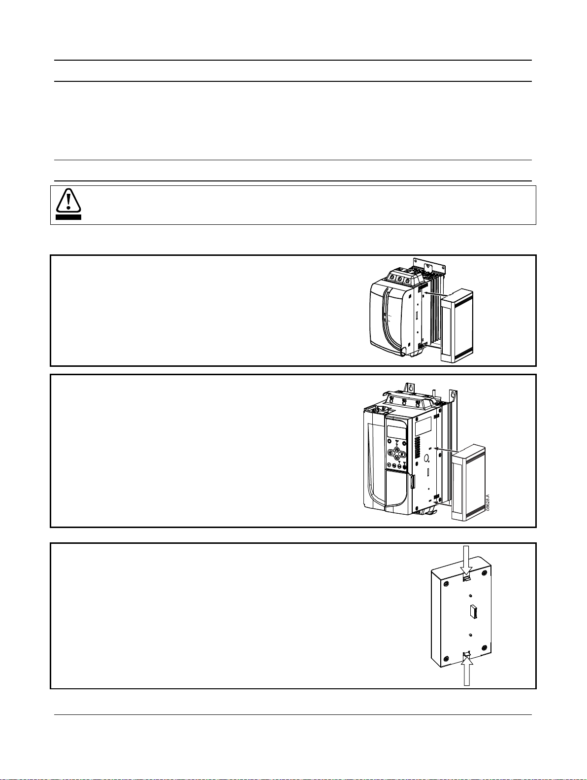
2. Installation
Remove mains and control voltage from the soft starter before attaching or removing accessories.
Install the Modbus Module using the following procedure:
Figure 2-1 Attach the module to the starter
Digistart CS
Plug the module onto the side of the soft starter.
Digistart IS :
1. Line the module up with the comms port slot.
2. Press the top retaining clip of the module into the soft starter
chassis.
3. Press in the bottom retaining clip.
Figure 2-2 Remove the module from the starter
Remove the module using the following procedure:
1. Take the module off-line.
2. Remove control power and mains supply from the soft starter.
3. Disconnect all field wiring from the module.
4. Push a small flat-bladed screwdriver into the slots at the top and bottom of the module
and depress the retaining clips.
5. Pull the module away from the soft starter.
4 Modbus Module User Guide
www.controltechniques.com Issue 1
Page 5
Protocol
Address
Baud Rate
Parity
Timeout
(seconds)
4800
OFF
OFF
9600
OFF
ON
19200
ON
38400
ON
ONOFF
No Parity
OFF
OFF
ODD
OFF
ON
EVENON10 bit
ON
ON
OFF
No Time Out
OFF
OFF
10 s
OFF
ON
60 sON100 s
ON
ONOFF
AP
ASCII
OFF
RTU
ON
Example: Address = 24
+16
+8
+4
+2
+1
0
0
0
0
0
ON
+16
+8
+4
+2
+1
0
0
0
0
0
ON
08649.A
1
2
3
08650.A
1
2
3
Modbus Module – RS485 serial port
DI2, +24V: Stop
NOTE
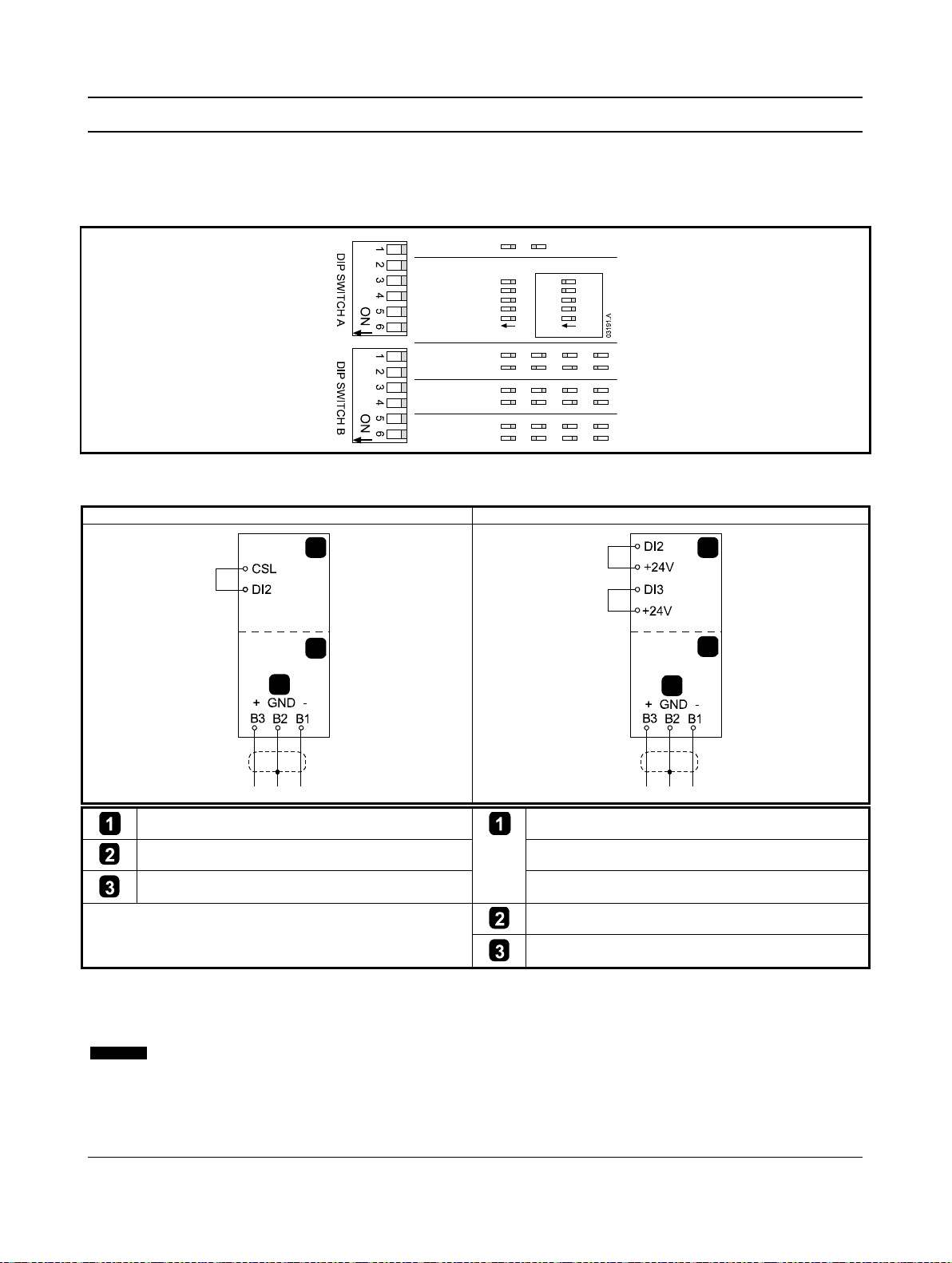
3. Modbus Module Connection and Configuration
3.1 Adjustment
Network communication parameters must be set on the Modbus Module. DIP switch settings take effect on the power-up of the Modbus
Module via the soft starter.
Figure 3-1 Adjustment switches
3.2 Connection
Figure 3-2 Modbus Module connec t io ns
Digistart CS Digistart IS
Digistart CS
RS485 connection onto Modbus network
For the Modbus Module to accept serial commands, a link must be fitted across terminals CSL-DI2 on Digistart CS starters.
Input links are required across terminals DI2, +24V and DI3, +24V if the Digistart IS soft starter is being operated in Remote mode. In
Local mode, links are not required.
Digistart IS Pr 3O Comms in Remote selects whether the soft starter will accept Start, Stop or Reset commands from the
Modbus Module User Guide 5
Issue 1 www.controltechniques.com
Serial Network Master while in Remote mode. See the Digistart IS User Manual for parameter details.
Digistart IS (Remote mode)
DI3, +24V: Reset
Modbus Module – RS485 serial port
RS485 connection onto Modbus network
Page 6

03193.C
1
NOTE
NOTE
3.3 Network Status LED
The Network Status LED (1) indicates the state of the communications link between the module and the network. LED operation is as
follows:
Figure 3-3 Feedback LEDs
Off No connection or soft starter not powered up
On Communication active
Flashing Communication inactive
If communication is inactive, the soft starter may trip if the Communications Timeout function has been set on the module.
When communication is restored, the soft starter will require a Reset.
4. Master Configuration
For standard Modbus 11-bit transmission, the Master must be configured for 2 stop bits with No Parity and 1 stop bit for odd or even
parity.
For 10-bit transmission, the Master must be configured for 1 stop bit.
In all cases, the Master baud rate and slave address must match those set on the Modbus Module DIP switches.
5. Modbus Functions
The Modbus Module supports the following Modbus functions:
• 03 Read multiple registers
• 06 Write single register
Modbus broadcast functions are not supported.
Digistart CS soft starters (including Remote Keypad):
• Read multiple registers 40003 to 40008
• Write single register 40002
Digistart IS so ft starters:
• Read multiple registers starting from 40003 up to a maximum of 119 register blocks.
• Write single register 40002 or 40009 to 40599.
A multiple read across register boundary 40008/40009 will result in a Modbus Error code 05 at the Master.
6 Modbus Module User Guide
www.controltechniques.com Issue 1
Page 7

5.1 Modbus register
Register
Type
Description
Digistart
Digistart IS
Remote
40002
Single
1 = Start
Command
write
2 = Stop
5 = Forced communication trip
6 = Start using Parameter Set 1
3
3
status
2 = Starting
3 = Running
check)
6 = Tripped
5
1 = Current exceeds full load current
1 = Initialised
7
0 = Communications are OK
1 = Communications device fault
40005 1
Multiple
Average 3 phase motor current (A)
temperature
Product type
read
0 to 2
Product parameter list version
and version
3 to 7
4 = Digistart CS
version
40009
2
Single
read
Pr 1A Motor Full Load Current to Digistart IS maximum
NOTE
Table 5-1 Modbus register
Address
3 = Reset
4 = Quick stop (coast to stop)
40003 Multiple Bit Description
Starter read
7 = Start using Parameter Set 2
0 to 3 1 = Ready
4 1 = Positive phase sequence (only valid if bit
6 0 = Uninitialised
4 = Stopping (including braking)
5 = Restart delay (including Temperature
7 = Program mode
8 = Jog forward
9 = Jog reverse
6 = 1)
CS
Keypad
40004
Trip Code
Motor current
40006
Motor
40007 Multiple Bit Description
40008
Serial protocol
Parameter
management
1
For Digistart IS models IS-0076B and smaller this value will be 10 times greater than the value displayed on the keypad.
2
See the relevant soft starter literature for a complete parameter list. The first product parameter is always allocated to register 40009.
The last product parameter is allocated to register 40XXX, where XXX = 008 plus total number of available parameters in the product.
3
Ensure that the programmable input is not set to Motor Set Select before using this function.
Multiple
read
read
Multiple
read
See Trip Code table
Motor 1 temperature (thermal model)
8 = Digistart IS
Multiple
read
write and
multiple
If Pr 3A Input A Function is set to motor set select, this will cause a conflict with motor set selection via serial
communications.
register address (starter software dependent)
Modbus Module User Guide 7
Issue 1 www.controltechniques.com
Page 8

Trip
Trip Name
Digistart CS
Digistart IS
2
Motor overload (thermal model)
4
Current imbalance
5
Frequency
6
Phase sequence
8
Power loss
11
Motor connection
13
FLC too high (FLC out of range)
16
Network communication (between module and network)
20
Ground fault
24
Input B trip
27
L2 phase loss
29
L1-T1 shorted
31
L3-T3 shorted
32
Motor 2 overload (thermal model)
37
RTD/PT100 A
39
RTD/PT100 C
41
RTD/PT100 E
43
RTD/PT100 G
47
Overpower
255
No trip
5.2 Trip codes
Table 5-2 Trip messages
Code
1 Excess start ti me
3 Motor thermistor
10 Heatsink overtemperature
12 Input A trip
14 Unsupported option (function not available in inside delta)
15 Starter communication (between module and soft starter)
17 Internal fault
18 Overvoltage
19 Undervoltage
23 Parameter out of range
26 L1 phase loss
28 L3 phase loss
30 L2-T2 shorted
331 Time-overcurrent (Bypass overload)
35 Battery/clock
36 Thermistor circuit
38 RTD/PT100 B
40 RTD/PT100 D
42 RTD/PT100 F
45 RTD/PT100 circuit
46 Analog input trip
48 Underpower
1
For Digistart IS, time-overcurrent protection is only available on internally bypassed models.
8 Modbus Module User Guide
www.controltechniques.com Issue 1
Page 9

5.3 Examples
Command: Start
Message
Starter Address
Function Code
Register Address
Data
CRC
In
20
06
40002
1
CRC1, CRC2
Out
20
06
40002
1
CRC1, CRC2
Starter status: Running
Message
Starter Address
Function Code
Register Address
Data
CRC
In
20
03
40003
1
CRC1, CRC2
Out
20
03 2 xxxx0011
CRC1, CRC2
Message
Starter Address
Function Code
Register Address
Data
CRC
Out
20
03 2 00000010
CRC1, CRC2
Download parameter from starter
Message
Starter Address
Function Code
Register Address
Data
CRC
In
20
03
40011
1
CRC1, CRC2
Out
20
03
2
10
CRC1, CRC2
Digistart IS Write parameter 12 (Pr 2H), Stop Mode, set = 4 'STV Soft Stop'
Message
Starter Address
Function Code
Register Address
Data
CRC
In
20
06
40020
4
CRC1, CRC2
Out
20
06
40019
4
CRC1, CRC2
Code
Description
Example
01
Illegal function code
Function other than 03 or 06
02
Illegal data address
Register number invalid
04
Not writable data
Register not allowed for data writing
06
Invalid command code
e.g. writing "6" into 40003
07
Illegal parameter read
Invalid parameter number
09
Unsupported command
Sending a serial command to Digistart IS with Pr 3O = Disable control in RMT.
NOTE
Trip code: Motor overload
In 20 03 40004 1 CRC1, CRC2
Digistart IS: Read parameter 3 (Pr 1C) Locked Rotor Time, 10 seconds
Upload parameter to starter
5.4 Modbus error codes
Table 5-3 Error codes
03 Not readable data Register not allowed for data reading
05 Data boundary fault Multiple data transfer across data boundary or data size more than 125
08 Illegal parameter write Invalid parameter number, read only, or hidden parameter
10 Local communication error Comm uni cation error between Modbus slave and starter
Some of the above codes are different from those defined in the Modbus Application Protocol Specification available
on
www.modbus.org .
Modbus Module User Guide 9
Issue 1 www.controltechniques.com
Page 10

NOTE
(Hexadecimal Character String)
Send address
EOT
(04h
[nn]
[nn]
[lrc]
[lrc]
ENQ or
05h)
Send request
(02h
[ccc]
[lrc]
03h)
Receive data
STX
(02h
[dddd]
[lrc]
[lrc]
ETX or
03h)
(06h)
NAK (negative acknowledge)
NAK
(15h)
or
ccc =
three byte ASCII command number where each character is represented by c.
dddd =
four byte ASCII number representing the current or temperature data where each decimal digit is represented by d.
ssss =
four byte ASCII number. The first two bytes are ASCII zero. The last two bytes represent the nibbles of a single byte of
address
command
Possible error responses:
NAK
(Invalid LRC)
(soft starter)
Command
ASCII
Comment
Start
B10
Initiates a start
Stop
B12
Initiates a stop
Reset
B14
Resets a trip state
ignored.
Forced communication trip
B18
Causes a communications trip
6. AP ASCII Protocol
The message fragments used to communicate with the Modbus Module as an AP ASCII slave device are shown below. The message
fragments may be assembled into complete messages as described in the sections that follow.
Data must be transmitted in 8-bit ASCII, no parity, one stop bit.
Table 6-1 AP ASCII message fragments
Send command STX [ccc] [lrc] ETX or
Receive status STX
ACK (acknowledge) ACK
Message Fragment Type
(02h
ASCII Character String or
[dddd]
[ssss]
[ssss]
or
[lrc]
[lrc]
ETX or
03h)
ERR (error) BEL
nn = two byte ASCII number representing the soft starter address where each decimal digit is represented by n.
(07h)
or
lrc = two byte longit udi nal redundancy check in hexadecimal.
status data in hexadecimal.
6.1 Commands
Commands can be sent to the soft starter using the following format:
Figure 6-1 Command format
Send
= Master
Quick stop B16 Initiates an immediate removal of voltage from the motor. Any soft stop settings are
ACK
Send
= Slave
ACK
10 Modbus Module User Guide
www.controltechniques.com Issue 1
Page 11

6.2 Status retrieval
=
Master
=
Slave
Request
ASCII
Receive Status (ssss)
Trip code
C18
See the trip code table.
2 = Starting
3 = Running
5 = Restart delay (including Temperature check)
7 = Program mode
5
1 = Current exceeds FLC
1 = Initialised
7
0 = Communications are OK
1 = Communications device fault
Send
ACK Send
Receive
=
Master
=
Slave
Request
ASCII
Receive Data (dddd)
Motor current
D10
Requests motor current. The data is four byte decimal ASCII. Minimum value 0000 A, maximum
temperature
data is four byte decimal ASCII. Minimum value is 0000%. Trip point is 0105%.
Soft starter status can be retrieved using the following format:
Figure 6-2 Status retrieval format
Send
address
Possible error responses:
ACK
Send
request
Receive
status
NAK (Invalid LRC)
Starter status C22 Bit Description
0 to 3 1 = Ready
4 = Stopping (including braking)
6 = Tripped
4 1 = Positive phase sequence (only valid if bit 6 = 1)
6 0 = Uninitialised
6.3 Data retrieval
Data can be retrieved from the soft starter using the following format:
Figure 6-3 Data retrieval format
address
Possible error responses:
request
(soft starter)
data
NAK (Invalid LRC)
(soft starter)
value 9999 A.
Motor
D12 Requests the calculated value of the motor thermal model as a % of motor thermal capacity. The
Modbus Module User Guide 11
Issue 1 www.controltechniques.com
Page 12

6.4 Calculating the checksum (LRC)
Each command string sent to and from the starter includes a checksum. The form used is the longitudinal redundancy check (LRC) in
ASCII hex. This is an 8-bit binary number represented and transmitted as two ASCII hexadecimal characters.
To calculate LRC:
1. Sum all ASCII bytes
2. Mod 256
3. 2's complement
4. ASCII convert
For example Command String (Start):
ASCII STX B 1 0
or 02h 42h 31h 30h
ASCII Hex Binary
STX 02h 0000 0010
B 42h 0100 0010
1 31h 0011 0001
0 30h 0011 0000
A5h 1010 0101 SUM (1)
A5h 1010 0101 MOD 256 (2)
5Ah 0101 1010 1's COMPLEMENT
01h 0000 0001 + 1 =
5Bh 0101 1011 2's COMPLEMENT (3)
ASCII 5 B ASCII CONVERT (4)
or 35h 42h LRC CHECKSUM
The complete command string becomes:
ASCII STX B 1 0 5 B ETX
or 02h 42h 31h 30h 35h 42h 03h
To verify a received message containing an LRC:
1. Convert last two bytes of message from ASCII to binary
2. Left shift 2nd to last byte four bits
3. Add to last byte to get binary LRC
4. Remove last two bytes from message
5. Add remaining bytes of message
6. Add binary LRC
7. Round to one byte
8. The result should be zero
Response or status bytes are sent from the starter as an ASCII string:
STX [d1]h [d2]h [d3]h [d4]h LRC1 LRC2 ETX
d1 = 30h
d2 = 30h
d3 = 30h plus upper nibble of status byte right shifted by four binary places
d4 = 30h plus lower nibble of status byte
For example status byte = 1Fh, response is:
STX 30h 30h 31h 46h LRC1 LRC2 ETX
12 Modbus Module User Guide
www.controltechniques.com Issue 1
Page 13

03250.B
1 2
3
Remote Keypad RS485
7. Modbus Control via Remote Keypad
To control a soft starter via an RS485 serial communications network using the Remote Keypad, connect the Remote Keypad to the
network as described in the following sections.
7.1 Grounding and shielding
Twisted pair data cable with ground shield is recommended. The cable shield should be connected to the GND device terminal at both
ends and one point of the site protective ground.
7.2 Termination resistors
In long cable runs prone to excessive noise interference, termination resistors should be installed between the data lines at bot h ends of
the RS485 cable. This resistance should match the cable impedance (typically 120
Figure 7-1 Installation with termination resistors
Network master RS485
Ω). Do not use wire wound resistors.
Soft starter RS485
7.3 RS485 data cable connection
Daisy chain connection is recommended. This is achieved by parallel connections of the data cable at the actual device terminals.
7.4 Remote Keypad RS485 network connection specifications
Input impedance: 12 kΩ
Common mode voltage range: - 7 V to + 12 V
Input sensitivity: ± 200 mV
Minimum differential output voltage: 1.5 V (with max loading of 54
Ω)
Modbus Module User Guide 13
Issue 1 www.controltechniques.com
Page 14

+ GND -
+ GND -
- GND +- GND ++ - ~/+ ~/-
1
2
4
3
B6, B7, B8 - RS485 network connection
NOTE
7.5 Using the Remote Keypad with Digistart CS
Figure 7-2 Modbus Module connec t io ns
Digistart CS
Modbus Module – RS485 serial port
Remote Keypad
B10, B11 - 4 to 20 mA analog output
B1, B2, B3 - RS485 starter connection
1, 2 - Supply voltage (18 to 30 Vac/Vdc)
RS485 Serial communication network connection
(Modbus RTU or AP ASCII)
7.6 Programming
The Remote Keypad must be configured to operate on the network. In order to access Programming Mode, the Remote Keypad must
be powered up when the soft starter is not running.
7.6.1 Programming Procedure
1. To enter Programming Mode, hold down the Data/Prog pushbutton for four seconds. The default value of the first parameter will
be displayed.
2. Use the Data/Prog pushbutton to advance to the next parameter.
3. Use the Stop and Reset pushbuttons to adjust parameter values.
Programming Mode closes when the Data/Prog pushbutton is pressed after Pr 9.
There is a 20 second timeout when the Remote Keypad is in Programming Mode. Programming Mode will automatically
close if no input is registered for 20 seconds. Any changes already made will be saved.
14 Modbus Module User Guide
www.controltechniques.com Issue 1
Page 15

7.6.2 Programmable Parameters
Parameter
Description
Default
Adjustable Range
satellite address
3
RS485 network
0 seconds
0 to 100 seconds
5
Modbus protocol
0
0 = no parity
6
Motor FLC (A)
10
1 to 2868
8
Start, Stop, Quick
0
0 = Remote Keypad and Network start, stop, quick stop function enabled.
Display
Indication
Problem
Possible Solution
SP flashing on
network.
The Remote Keypad offers the following programmable parameters:
Table 7-1 Programmable parameters
Number
1 RS485 network
baud rate
Setting
4
(9600 baud)
2 = 2400 baud
3 = 4800 baud
4 = 9600 baud
5 = 19200 baud
6 = 38400 baud
2 RS485 network
timeout
4 RS485 network
protocol
parity
20 1 t o 99
(= off)
1
(AP ASCII)
(no parity)
1 = AP ASCII protocol
2 = Modbus RTU protocol
1 = odd parity
2 = even parity
3 = 10-bit transmission
7 Analog output
100 80 to 120
4 mA offset (%)
stop function
disable
9
1
Remote Keypad Reset pushbutton is always enabled.
2
RS485 Network reset and forced communication trip functions are always enabled.
Current ÷ 10
0 0 = off (required for Digistart CS)
1 = Remote Keypad start, stop, quick stop function enabled. Network start, stop,
quick stop function disabled.
2 = Remote Keypad start, stop, quick stop function disabled. Network start, stop,
quick stop function enabled.
3 = Remote Keypad start, stop, quick stop function disabled. Network start, stop,
quick stop function disabled.
1
2
1, 2
1 = on (not suitable for Digistart CS)
7.7 Troubleshooting
The Remote Keypad display and status indication LEDs can indicate abnormal operating and system conditions.
Table 7-2 Error codes
nEt on display
A loss of communication has
been detected on the RS485
link to the network.
The Remote Keypad has an RS485 Network Timeout Protection setting (Pr 3). This
error is reported when no communication occurs for longer than the timeout setting.
The system will become active as soon as communication is restored.
To clear nEt from the display, press the Data/Prog pushbutton momentarily or send
a Reset command from the network Master.
Soft starter is off and being
display
Modbus Module User Guide 15
programmed from the serial
Finish soft starter network programming procedure and exit Programming Mode.
Issue 1 www.controltechniques.com
Page 16

8. Specifications
Enclosure
Dimensions ........................................................................................................................... 35 mm (W) x 157 mm (H) x 90 mm (D)
Weight ..................................................................................................................................................................................... 250 g
Protection .................................................................................................................................................................................. IP20
Mounting
Spring-action plastic mounting clips (x 2)
Connections
Soft starter ......................................................................................................................................................... 6-way pin assembly
Network ................................................................................................... 5-way male and unpluggable female connector (supplied)
Maximum cable size ........................................................................................................................................................... 2.5 mm2
Settings
Protocol ....................................................................................................................................................... Modbus RTU, AP ASCII
Address range ....................................................................................................................................................................... 0 to 31
Data rate (bps) ......................................................................................................................................... 4800, 9600, 19200, 38400
Parity .......................................................................................................................................................... None, Odd, Even, 10-bit
Timeout ................................................................................................................................................. None (off), 10 s, 60 s, 100 s
Certification
C ........................................................................................................................................................................... IEC 60947-4-2
CE ............................................................................................................................................................................ IEC 60947-4-2
16 Modbus Module User Guide
www.controltechniques.com Issue 1
 Loading...