

Page 1
Integrated Cabinet Solutions
For Business-Critical Continuity™
Knurr® DCM™ Rack
User Manual
Page 2

IMPORTANT SAFETY GUIDELINES
SAVE THESE INSTRUCTIONS
This manual contains important instructions that should be closely followed during installation and
maintenance of this unit. Read all safety instructions before attempting to assemble and install the
Knurr DCM. Adhere to all warnings on the unit and in this manual. Follow all instructions.
Read all warnings, cautions and instructions in this before attempting to move, lift, remove packaging
from or preparing unit for installation.
This product is designed for commercial / industrial use only. This product is not intended for use
with life support or o ther U.S. F DA desi gnated “cri tical” devices. Maximum load must not exceed th at
shown on the Knurr DCM rating label.
Operate this product i n a cl ean, ind oor enviro nment t h at i s f re e o f moisture, fl a mm ab le li q ui ds, gas e s
and corrosive substances.
Ensure that the Knurr DCM has proper ventilation. Never block or insert objects into the ventilation
holes or other openings. Ma intain a minimum cle arance of 12 inches (305mm) in front, rear and top of
the Knurr DCM for proper air flow and cooling.
Page 3

TABLE OF CONTENTS
1.0 INTRODUCTION . . . . . . . . . . . . . . . . . . . . . . . . . . . . . . . . . . . . . . . . . . . . . . . . . . . . . . . . . .1
1.1 Feedback on Equipment, Instructions . . . . . . . . . . . . . . . . . . . . . . . . . . . . . . . . . . . . . . . . . . . 1
2.0 MAJOR COMPONENTS . . . . . . . . . . . . . . . . . . . . . . . . . . . . . . . . . . . . . . . . . . . . . . . . . . . .2
2.1 Frame . . . . . . . . . . . . . . . . . . . . . . . . . . . . . . . . . . . . . . . . . . . . . . . . . . . . . . . . . . . . . . . . . . . . . 2
2.2 Enclosure . . . . . . . . . . . . . . . . . . . . . . . . . . . . . . . . . . . . . . . . . . . . . . . . . . . . . . . . . . . . . . . . . . 2
2.2.1 Doors . . . . . . . . . . . . . . . . . . . . . . . . . . . . . . . . . . . . . . . . . . . . . . . . . . . . . . . . . . . . . . . . . . . . . . . 2
2.2.2 Side Panels . . . . . . . . . . . . . . . . . . . . . . . . . . . . . . . . . . . . . . . . . . . . . . . . . . . . . . . . . . . . . . . . . . 2
2.3 Mounting Hardware. . . . . . . . . . . . . . . . . . . . . . . . . . . . . . . . . . . . . . . . . . . . . . . . . . . . . . . . . . 3
3.0 INSTALLATION . . . . . . . . . . . . . . . . . . . . . . . . . . . . . . . . . . . . . . . . . . . . . . . . . . . . . . . . . .4
3.1 Inspection . . . . . . . . . . . . . . . . . . . . . . . . . . . . . . . . . . . . . . . . . . . . . . . . . . . . . . . . . . . . . . . . . . 4
3.2 Required Setup Equipment . . . . . . . . . . . . . . . . . . . . . . . . . . . . . . . . . . . . . . . . . . . . . . . . . . . . 4
3.3 Unloading the Knurr DCM . . . . . . . . . . . . . . . . . . . . . . . . . . . . . . . . . . . . . . . . . . . . . . . . . . . . 5
3.4 Equipment Layout . . . . . . . . . . . . . . . . . . . . . . . . . . . . . . . . . . . . . . . . . . . . . . . . . . . . . . . . . . . 5
3.5 Basic Hardw a re In st a ll a t i on —Nutbars and Spring Nuts . . . . . . . . . . . . . . . . . . . . . . . . . . . . 6
3.5.1 Inserting a Nutbar or Spring Nut . . . . . . . . . . . . . . . . . . . . . . . . . . . . . . . . . . . . . . . . . . . . . . . . 6
3.6 Frame and Enclosure Configurations . . . . . . . . . . . . . . . . . . . . . . . . . . . . . . . . . . . . . . . . . . . . 7
3.6.1 Internal Mounting Rails. . . . . . . . . . . . . . . . . . . . . . . . . . . . . . . . . . . . . . . . . . . . . . . . . . . . . . . . 7
3.6.2 Front- and Rear-Mount Rails—Position and Attach . . . . . . . . . . . . . . . . . . . . . . . . . . . . . . . . . 8
3.7 Door—Remove and Reverse. . . . . . . . . . . . . . . . . . . . . . . . . . . . . . . . . . . . . . . . . . . . . . . . . . . 10
3.7.1 Remove the Door. . . . . . . . . . . . . . . . . . . . . . . . . . . . . . . . . . . . . . . . . . . . . . . . . . . . . . . . . . . . . 11
3.7.2 Reverse the Door. . . . . . . . . . . . . . . . . . . . . . . . . . . . . . . . . . . . . . . . . . . . . . . . . . . . . . . . . . . . . 11
3.7.3 Reverse the Door Handle . . . . . . . . . . . . . . . . . . . . . . . . . . . . . . . . . . . . . . . . . . . . . . . . . . . . . . 11
3.8 Side Panels—Remove and Replace . . . . . . . . . . . . . . . . . . . . . . . . . . . . . . . . . . . . . . . . . . . . . 12
3.8.1 Remove a Panel. . . . . . . . . . . . . . . . . . . . . . . . . . . . . . . . . . . . . . . . . . . . . . . . . . . . . . . . . . . . . . 12
3.8.2 Replace a Side Panel . . . . . . . . . . . . . . . . . . . . . . . . . . . . . . . . . . . . . . . . . . . . . . . . . . . . . . . . . 12
4.0 OPTIONS—INSTALLATION . . . . . . . . . . . . . . . . . . . . . . . . . . . . . . . . . . . . . . . . . . . . . . . . .13
4.1 Anti-Tilt Kit (Part # 540254G1L) . . . . . . . . . . . . . . . . . . . . . . . . . . . . . . . . . . . . . . . . . . . . . 13
4.2 1U Tool-Less Fi xe d Sh e l f In st a l l a ti o n. . . . . . . . . . . . . . . . . . . . . . . . . . . . . . . . . . . . . . . . . . . 14
4.3 1U Tool-Less T e le scopic Shelf . . . . . . . . . . . . . . . . . . . . . . . . . . . . . . . . . . . . . . . . . . . . . . . . . 14
4.4 2U Locking Drawer Installati o n . . . . . . . . . . . . . . . . . . . . . . . . . . . . . . . . . . . . . . . . . . . . . . . 15
4.5 Power Distribution Unit Mounting . . . . . . . . . . . . . . . . . . . . . . . . . . . . . . . . . . . . . . . . . . . . . 16
4.5.1 Install Tool-Less PDU Mounting Brackets—700 and 800mm Cabinets Only . . . . . . . . . . . . 16
4.5.2 Full-Height PDU Mounting Brackets . . . . . . . . . . . . . . . . . . . . . . . . . . . . . . . . . . . . . . . . . . . . 17
4.6 Install RPC™ BDM™ Mounting Brackets . . . . . . . . . . . . . . . . . . . . . . . . . . . . . . . . . . . . . . . 18
4.7 Tool-Less Blanking Panels. . . . . . . . . . . . . . . . . . . . . . . . . . . . . . . . . . . . . . . . . . . . . . . . . . . . 19
4.8 Cluster Configuration . . . . . . . . . . . . . . . . . . . . . . . . . . . . . . . . . . . . . . . . . . . . . . . . . . . . . . . 2 0
4.8.1 Connect Two Racks Using the Tool-Less Cluster Kit. . . . . . . . . . . . . . . . . . . . . . . . . . . . . . . . 20
4.8.2 Connect Two Racks Using the Factory-Installed Cluster Tab. . . . . . . . . . . . . . . . . . . . . . . . . 20
4.9 Cable Management. . . . . . . . . . . . . . . . . . . . . . . . . . . . . . . . . . . . . . . . . . . . . . . . . . . . . . . . . . 2 1
4.10 Cable Access —T o p Cove r, Back and Base . . . . . . . . . . . . . . . . . . . . . . . . . . . . . . . . . . . . . . . 22
i
Page 4

4.11 Top Cover Cable Management Kit . . . . . . . . . . . . . . . . . . . . . . . . . . . . . . . . . . . . . . . . . . . . . 22
4.11.1 Internal Cable Management Troughs . . . . . . . . . . . . . . . . . . . . . . . . . . . . . . . . . . . . . . . . . . . . 24
4.11.2 1U Cable Routing Panel. . . . . . . . . . . . . . . . . . . . . . . . . . . . . . . . . . . . . . . . . . . . . . . . . . . . . . . 24
4.12 Attach Cable Management Option—Cable Fingers . . . . . . . . . . . . . . . . . . . . . . . . . . . . . . . . 25
4.12.1 Install a Liebert MB Mounting Bracket . . . . . . . . . . . . . . . . . . . . . . . . . . . . . . . . . . . . . . . . . . 25
5.0 MAINTENANCE . . . . . . . . . . . . . . . . . . . . . . . . . . . . . . . . . . . . . . . . . . . . . . . . . . . . . . . . .27
5.1 Periodic Maintenance. . . . . . . . . . . . . . . . . . . . . . . . . . . . . . . . . . . . . . . . . . . . . . . . . . . . . . . . 27
6.0 SPECIFICATIONS. . . . . . . . . . . . . . . . . . . . . . . . . . . . . . . . . . . . . . . . . . . . . . . . . . . . . . . .28
7.0 ACCESSORIES . . . . . . . . . . . . . . . . . . . . . . . . . . . . . . . . . . . . . . . . . . . . . . . . . . . . . . . . .29
FIGURES
Figure 1 Side panel lock components . . . . . . . . . . . . . . . . . . . . . . . . . . . . . . . . . . . . . . . . . . . . . . . . . . . . . . . . 3
Figure 2 Knurr DCM as shipped. . . . . . . . . . . . . . . . . . . . . . . . . . . . . . . . . . . . . . . . . . . . . . . . . . . . . . . . . . . . 4
Figure 3 Removing rack from shipping pallet . . . . . . . . . . . . . . . . . . . . . . . . . . . . . . . . . . . . . . . . . . . . . . . . . 5
Figure 4 T-slot configuration and nutbar. . . . . . . . . . . . . . . . . . . . . . . . . . . . . . . . . . . . . . . . . . . . . . . . . . . . . 6
Figure 5 Insert nutbar or spring nut . . . . . . . . . . . . . . . . . . . . . . . . . . . . . . . . . . . . . . . . . . . . . . . . . . . . . . . . 7
Figure 6 Vertical rail repositioning—600mm cabinet . . . . . . . . . . . . . . . . . . . . . . . . . . . . . . . . . . . . . . . . . . . 8
Figure 7 Vertical rail repositioning—700 and 800mm cabinets . . . . . . . . . . . . . . . . . . . . . . . . . . . . . . . . . . . 9
Figure 8 Door hinge removal. . . . . . . . . . . . . . . . . . . . . . . . . . . . . . . . . . . . . . . . . . . . . . . . . . . . . . . . . . . . . . 11
Figure 9 Anti-Tilt Legs installed. . . . . . . . . . . . . . . . . . . . . . . . . . . . . . . . . . . . . . . . . . . . . . . . . . . . . . . . . . . 13
Figure 10 1U tool-less fixed shelf installation point . . . . . . . . . . . . . . . . . . . . . . . . . . . . . . . . . . . . . . . . . . . . 14
Figure 11 1U tool-less telescopic shelf installation . . . . . . . . . . . . . . . . . . . . . . . . . . . . . . . . . . . . . . . . . . . . . 15
Figure 12 Locking drawer . . . . . . . . . . . . . . . . . . . . . . . . . . . . . . . . . . . . . . . . . . . . . . . . . . . . . . . . . . . . . . . . . 15
Figure 13 Small PDU mounting bracket on rack frame . . . . . . . . . . . . . . . . . . . . . . . . . . . . . . . . . . . . . . . . . 16
Figure 14 Full-height PDU mounting brackets . . . . . . . . . . . . . . . . . . . . . . . . . . . . . . . . . . . . . . . . . . . . . . . . 18
Figure 15 RPC BDM mounting brackets and fasteners . . . . . . . . . . . . . . . . . . . . . . . . . . . . . . . . . . . . . . . . . 18
Figure 16 Installing tool-less blanking panels. . . . . . . . . . . . . . . . . . . . . . . . . . . . . . . . . . . . . . . . . . . . . . . . . 19
Figure 17 Cluster connections. . . . . . . . . . . . . . . . . . . . . . . . . . . . . . . . . . . . . . . . . . . . . . . . . . . . . . . . . . . . . . 20
Figure 18 Top cover for Knurr DCM cabinets 42U and 45U high . . . . . . . . . . . . . . . . . . . . . . . . . . . . . . . . . 22
Figure 19 Dress panels along edge of cluster of Knurr DCMs . . . . . . . . . . . . . . . . . . . . . . . . . . . . . . . . . . . . 23
Figure 20 Internal cable trough installation . . . . . . . . . . . . . . . . . . . . . . . . . . . . . . . . . . . . . . . . . . . . . . . . . . 24
Figure 21 1U Cable Routing Panel installation. . . . . . . . . . . . . . . . . . . . . . . . . . . . . . . . . . . . . . . . . . . . . . . . 24
Figure 22 Cluster cable routing components—assembled and installed . . . . . . . . . . . . . . . . . . . . . . . . . . . . 25
Figure 23 Liebert MB mounting brackets . . . . . . . . . . . . . . . . . . . . . . . . . . . . . . . . . . . . . . . . . . . . . . . . . . . . 25
Figure 24 Liebert MB mounting bracket inserted into Knurr DCM. . . . . . . . . . . . . . . . . . . . . . . . . . . . . . . . 26
Figure 25 Knurr DCM model numbers. . . . . . . . . . . . . . . . . . . . . . . . . . . . . . . . . . . . . . . . . . . . . . . . . . . . . . . 28
TABLES
Table 1 Rack dimensions . . . . . . . . . . . . . . . . . . . . . . . . . . . . . . . . . . . . . . . . . . . . . . . . . . . . . . . . . . . . . . . . . 1
Table 2 Door dimensions, single door . . . . . . . . . . . . . . . . . . . . . . . . . . . . . . . . . . . . . . . . . . . . . . . . . . . . . . 10
Table 3 Door dimensions, split door . . . . . . . . . . . . . . . . . . . . . . . . . . . . . . . . . . . . . . . . . . . . . . . . . . . . . . . 10
Table 4 Optional side/partition panel sizes and part numbers . . . . . . . . . . . . . . . . . . . . . . . . . . . . . . . . . . 12
Table 5 Knurr DCM quick-ship part numbers . . . . . . . . . . . . . . . . . . . . . . . . . . . . . . . . . . . . . . . . . . . . . . . 28
Table 6 Accessories part numbers and descriptions. . . . . . . . . . . . . . . . . . . . . . . . . . . . . . . . . . . . . . . . . . . 29
ii
Page 5

1.0 INTRODUCTION
The highly versatile Knurr DCM provide an organized, se cure, controlled environment in a single
system for sensitive electronic equipment.
The Knurr DCM is available in three heights—24U, 42U and 45U (47", 78.5" and 83.9"; 1196mm,
1996mm and 2131mm). Those cabinet heights are available in these widths and depths:
Table 1 Rack dimensions
Dimensions, in (mm)
Rack
Size
24U 46.0 (1168) 46.6 (1186) 47.1 (1199) 23.3 (591) 23.6 (600) 38.8 (986) 39.4 (1000)
42U 77.5 (1968) 78.1 (1986) 78.6 (1999) 27.2 (691) 27.6 (700) 42.8 (1086) 43.3 (1100)
45U 82.8 (2103) 83.4 (2121) 83.9 (2134) 31.1 (791) 31.5 (800) 46.7 (1186) 47.2 (1200)
Height, width, and depth dimensions are independent
Frame Only W/ Leveling Feet W/ Casters W/O Sides W/ Sides W/O Doors W/ Doors
Assembly instructions in this manual cover the various configurations of the Knurr DCM, either a
single rack for simple equipment organization or a suite of Knurr DCM racks.
1.1 Feedback on Equipment, Instructions
Height Width Depth
Introduction
Emerson Network Power is highly interested in providing high quality equipment and clear, concise
instructions on installing and using the Knurr DCM and its optional equipment. If you have any
comments about the rack, its options or instructions, visit
www.emersonnetworkpower/DCMfeedback
1
Page 6

2.0 MAJOR COMPONENTS
A Knurr DCM may have any or all of the components addressed in this section, dependin g on its
configuration.
2.1 Frame
The base of all Knurr DCM products is the frame. The Knurr DCM features a fully assembled,
extruded aluminum frame with a patented T-slot that permits many of the cabinet’s tool-less
mounting features.
The racks can accommodate shelf- or rack-mounted equipment on 19-inch (483mm) adjustable rails.
See Knurr DCM model numbers on page 28 and illustrations for meas urements of different
models.
Cutouts in the top covers permit customer cable entry. The top of the Knurr DCM also is drilled for
mounting a Liebert XDV top-mount cooling unit.
2.2 Enclosure
Exterior components of the Knurr DCM are painted black (RAL 7021)
2.2.1 Doors
All doors are framed from sheet metal and have hexagonal perforations leaving 83 percent of the door
open to airflow for efficient cooling. A two-point latch and push button lock come standard.
Doors are available in single- or dual-door designs for easier access. All doors are removable and
single doors are designed for reversible (left/right) hinging (see 3.7.1 - Remove the Door and 3.7.2 -
Reverse the Door). Each type of door swings 135 degrees. Each door is perforated; each is available
in RAL 7021, matching the rack
Major Components
Doors are available in these styles and sizes:
• 1200mm x 600mm, single, Part # 538444G1L
• 1200mm x 600mm, split, Part # 539273G1L
• 1200mm x 700mm, single,
• 1200mm x 700mm, split, Part # 539273G2L
• 1200mm x 800mm, single, Part # 538444G3L
• 1200mm x 800mm, split, Part # 539273G3L
• 2000mm x 600mm, single, Part # 538444G4L
• 2000mm x 600mm, split, Part # 539273G4L
• 2000mm x 700mm, single, Part # 538444G5L
• 2000mm x 700mm, split, Part # 539273G5L
• 2000mm x 800mm, single, Part # 538444G6L
• 2000mm x 800mm, split, Part # 539273G6L
• 2100mm x 600mm, single, Part # 538444G7L
• 2100mm x 600mm, split, Part # 539273G7L
• 2100mm x 700mm, single, Part # 538444G8L
• 2100mm x 700mm, split, Part # 539273G8L
• 2100mm x 800mm, single, Part # 538444G9L
• 2100mm x 800mm, split, Part # 539273G9L
2.2.2 Side Panels
Side panels for each size cabinet are fashioned from sheet metal. Quarter-turn fasteners outside the
unit permit removal of all panels for maintenance while preserving internal security during normal
operation.
Part # 538444G2L
An optional side panel lock with keys (Part # 011399067L) is available to secure the side panel. The
lock insert is installed near the bottom center of the side panel.
2
Page 7
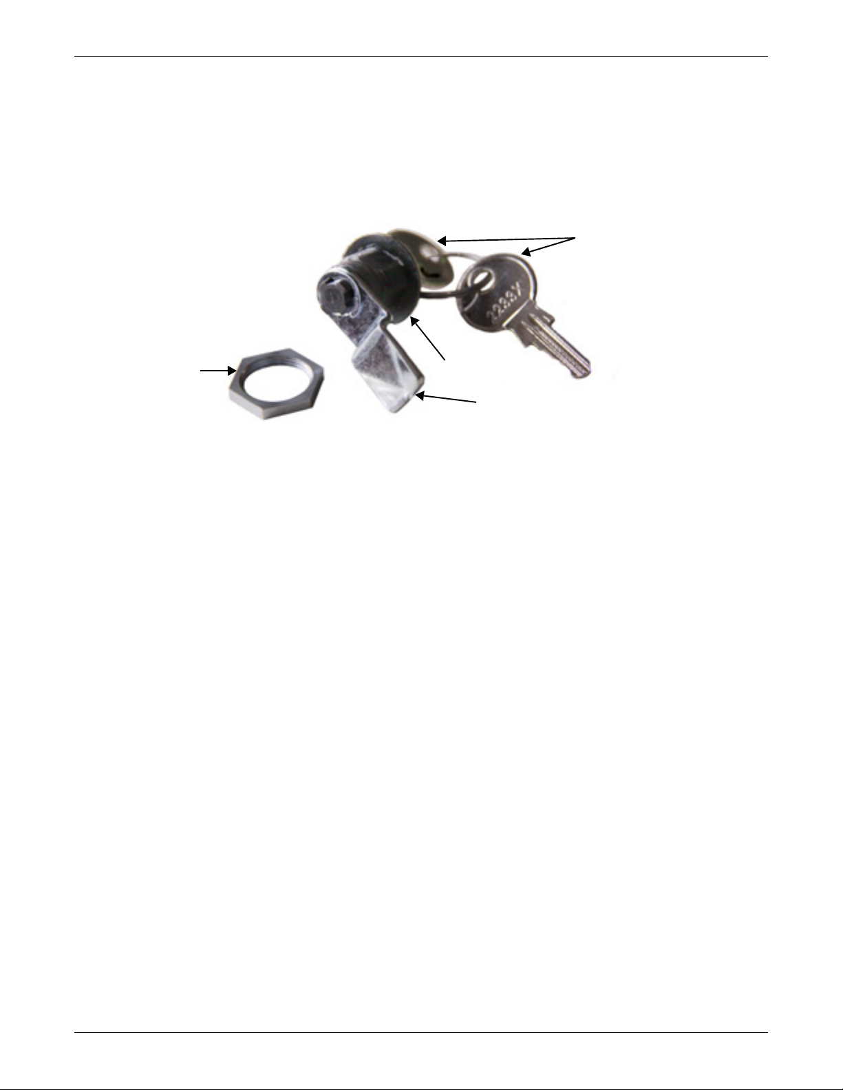
To install the Side Panel Lock:
Side Panel Lock
cylinder
Nut to secure Side
Panel Lock to panel
Keys
Side Panel Lock
cam
1. Insert a key into the lock to use as a handle.
2. Remove the locking nut from the cylinder.
3. Insert the lock, cam first, into the panel. The cam should be pointed to the right.
4. Slip the nut over the cam and tighten it onto the plastic lock cylinder.
5. Test the lock to ensure that it operates properly.
Figure 1 Side panel lock components
Major Components
2.3 Mounting Hardware
Hardware to install all options is shipped with the Knurr DCM. Bags of nuts, screws, washers and
other mounting hardware are attached to the frame. Some mounting hardware ships inside the box
containing the optional equipment.
• 50 each: 10-32 cagenuts, screws and rosette washers
• 20 M5 spring nuts
• 20 M5 screws
• 4mm hex Allen wrench
3
Page 8
3.0 INSTALLATION
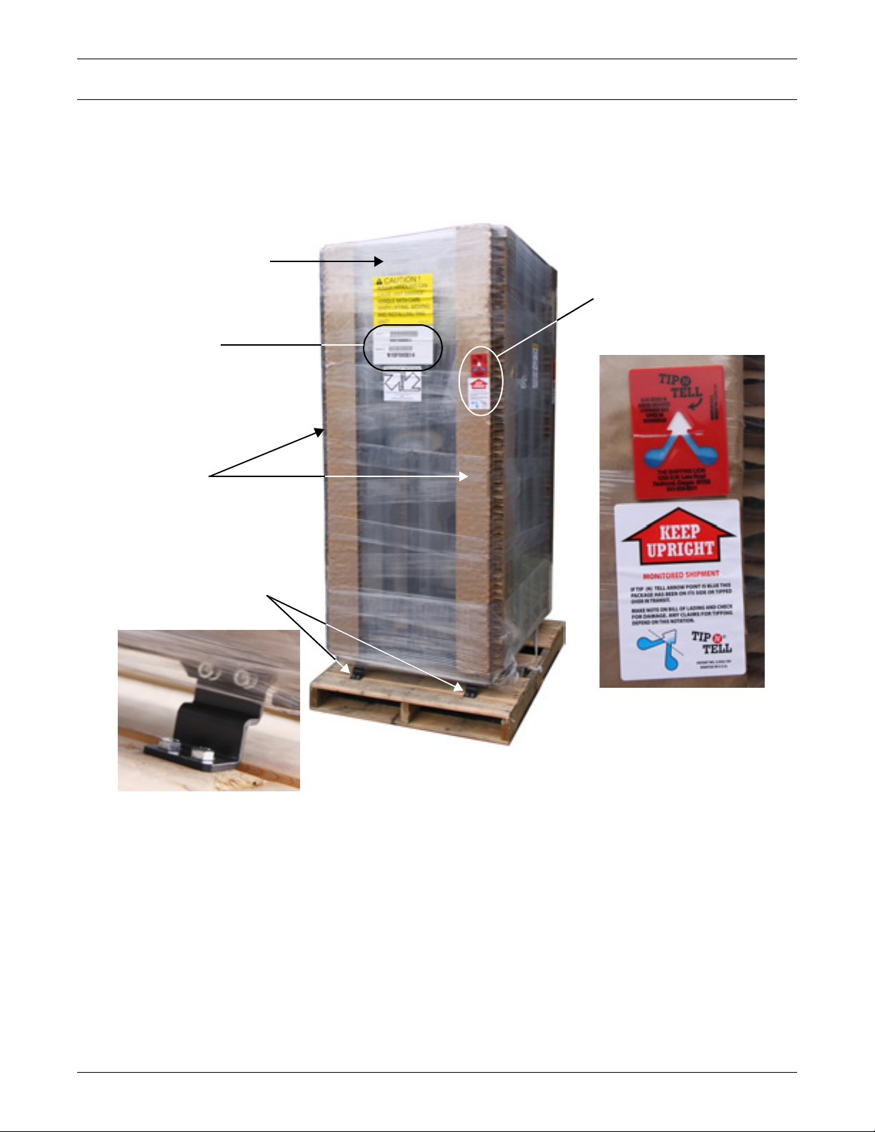
Tilt Indicator shows
whether the unit was been
tilted beyond the allowable
limit or mishandled during
shipping
Braces secure Knurr DCM
to shipping pallet; one at
each corner
Shrink wrap secures corrugated
corner protectors to the Knurr
DCM and shields the unit from
contact damage
Corrugated Corner
Protectors at each
corner
Part Number and
Serial Number
3.1 Inspection
Upon receiving a Knurr DCM, examine the packaging for any signs of mishandling or damage. If any
damage is noted, notify your local Liebert representativ e and your carrier immediately.
Figure 2 Knurr DCM as shipped
Installation
3.2 Required Setup Equipment
Each Knurr DCM ships with all the tools necessary to remove the unit from the pallet. The tool kit,
(Part # 542665G1) contains the following tools:
•1 M5 Allen Wrench
•1 M6 Allen Wrench
• 1 Torx L Key ,T30
The following tools are required to set up a Knurr DCM:
• pallet jack or forklift
• utility knife or scissors
• 9/16" ratchet or wrench
• 6mm hex wrench
4
Page 9
3.3 Unloading the Knurr DCM
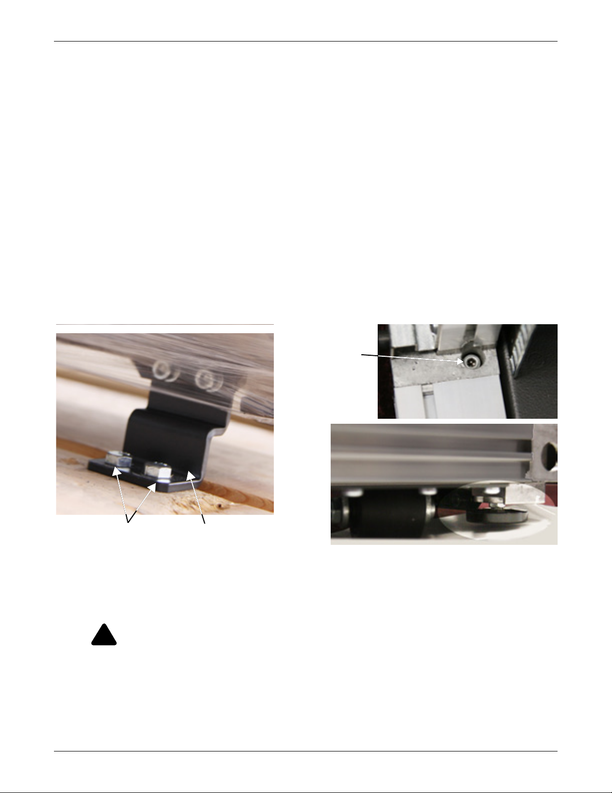
!
Raise leveling feet
by turning the hex
nut on each foot
(one at each corner).
... to free the shipping
braces from the pallet.
Remove lag bolts at each
corner of the rack ...
Before unloading a Knurr DCM, note the weight of the model (see 6.0 - Specifications. Use at least
two people when moving the unit.
1. Using a pallet jack or forklift, move the Knurr DCM on its pallet to the installation location.
2. Cut the shrink wrap and remove all packaging.
3. Remove the lag bolts securing each shipping bracket to the shipping pallet; there is one bracket at
each corner of the Knurr DCM; each bracket has two lag bolts (see Figure 3).
4. Raise the leveling feet so that the rack will rest on the feet:
a. Use the supplied hex wrench to lower each caster until the Knurr DCM is not resting on the
shipping brackets.
b. Remove the hex bolts securing the shipping brackets to the Knurr DCM.
Leave the shipping brackets attached if they will be used to secure the cabinet to the floor.
5. Use a pallet jack or forklift to raise the Knurr DCM off the shipping pallet.
6. Slide the shipping pallet out from under the rack.
The Knurr DCM may be position ed for installation either with the forklift, by two or more people
carrying it or by rolling the cabinet on its casters.
If the casters are to be used to move the cabinet, the leveling feet must be raised by reversing Step 4
above. Position the cabinet and either lower the leveling feet or bolt the cabinet to the floor with the
shipping brackets.
Figure 3 Removing rack from shipping pallet
Installation
3.4 Equipment Layout
To keep the unit’s center of gr av ity a s l ow as pos sible, install equipment from the bottom up, starting
with the heavier units. Leave any unused space at the top of the enclosure.
CAUTION
After equipment is installed, the Knurr DCM may ha ve a high center of grav ity. Avoid tipping
the unit when it is being moved.
5
Page 10
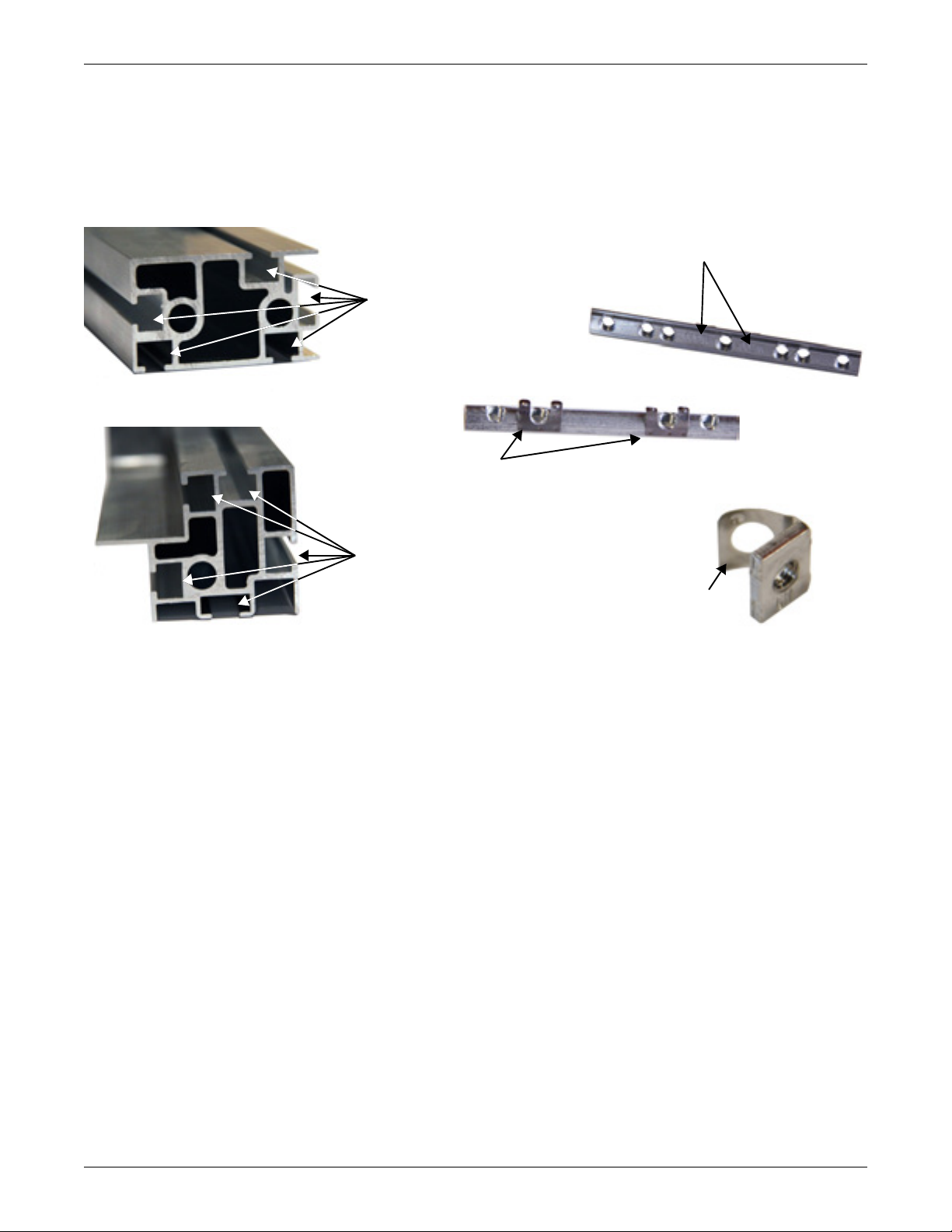
3.5 Basic Hardware Installation—Nutbars and Spring Nuts
Nutbar, Front (above)
and Back (below)
Leaf Springs Stabilize
Nutbar in T-Slot
"W700" and "W80 0"
Stamped on face of
M5 nutbar
Cross-Section of Horizontal
Knurr DCM Frame Member
T-Slots
Spring Nut
Leaf Spring Stabilizes
Spring Nut in T-Slot
T-Slots
Cross-Section of Vertical
Knurr DCM Frame Member
The Knurr DCM is designed with T-slots on exposed faces of the aluminum frame membe rs. These
T-slots permit placing nutbars and spring nuts anywhere along a frame member to mount equipment
at any distance desired (see Figure 4). Nutbars and spring nuts accept M5 and M6 screws used to
attach most equipment and options to the rack’s aluminum frame members.
Figure 4 T-slot configuration and nutbar
Installation
3.5.1 Inserting a Nutbar or Spring Nut
To insert a nutbar or spring nut into a T-slot on the Knurr DCM frame, compress the spring on the
back of the nutbar and slip it into the T-slot (see Figure 5). If the nutbar or spring nut does not
flatten out into the slot, press down on the edge of the block that is too high.
Properly installed nutbars and spring nuts have the thread hole section on the outer side of the T-slot
(see Figure 5). The leaf spring holds the nutbar or spring nut in place while a screw is threaded and
tightened. Nutbars and spring nut s can be pressed down with a small tool and moved for better
alignment.
6
Page 11
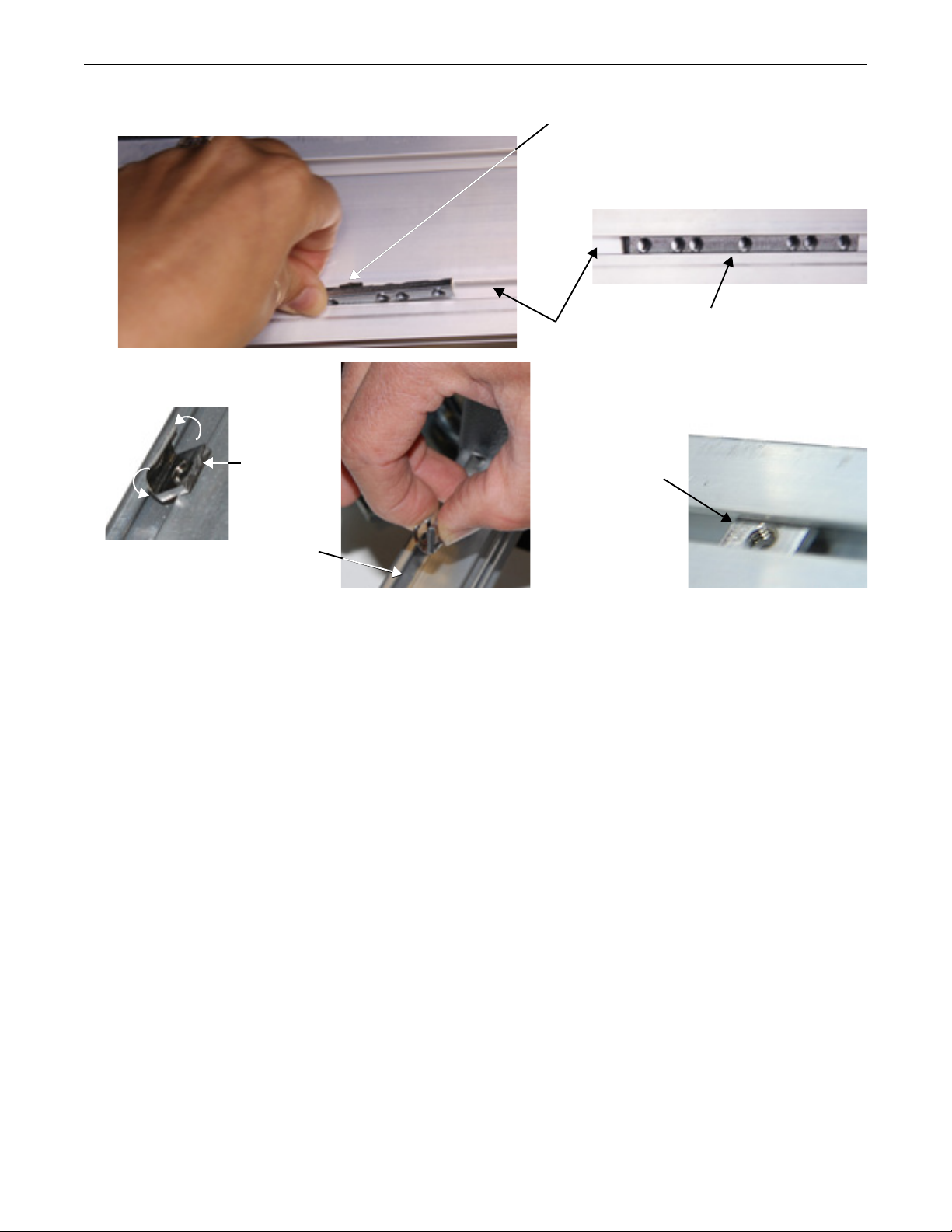
Figure 5 Insert nutbar or spring nut
T-Slot in
Frame
Nutbar in T-Slot
Press leaf spring and slip
edge into T-slot. Flip
nutbar as it slides in.
Spring nut oriented
for insertion into T-Slot
This end
of spring
nut flips
over and
nut slips
into T-Slot
T-Slot
Spring nut
in T-Slot
Installation
3.6 Frame and Enclosure Configurations
3.6.1 Internal Mounting Rails
The Knurr DCM can accommodate rack-mounted or fre e-standi ng comput er and net wo rk equipme nt.
The unit features 19-inch (4 83mm) rack rail s. These in ternal front- a nd rear-mount rai ls are desi gned
in accordance with the EIA 310D rack standard. The rails are adjustable for installing equipment of
different sizes.
Accesories compatible with the 19" rails includes a tool-l ess fixed shelf (Part # 002185000, L-shaped
depth-adjustable support rail (Part # 542777G1), a tool -less telescopic shelf (Part # 535809G1) and
a lockable, fully enclosed 2 U drawer (Part # 011139278). Each is supplied with installation
hardware.
7
Page 12

3.6.2 Front- and Rear-Mount Rails—Position and Attach
Quarter-T urn Mecha n i cal
Fasteners in T-Slot in
Aluminum Frame at Top
of Cabinet
T-Slot in
Frame
Quarter-Turn Mechanical
Fasteners in T-Slot in
Aluminum Frame at Bottom
of Cabinet
Quarter-Turn Mechanical
Fastener in T-Slot in
Center Depth Support
Front- and rear-mount vertical rails are installed in the Knurr DCM at the factory at 29.13inches
(740mm). They are secured to the 600mm Knurr DCM’s aluminum frame using threaded block
nutbars in the T-slot at top and bottom of the EIA rail and M6 x 12 screws. Mechanical fasteners in
are used in center of the EIA rai l to tie into the center depth supp ort member. Vertical rails are
installed in the 700 and 800mm Knurr DCM using a cross-brace at the top; node brackets are used at
the bottom and on the center horizontal rails. The cross-brace and node brackets att ach to the cabinet
frame with Torx head screws and nutbar. The rails can be moved to change the front-to-rear distance
between the rails.
NOTE
The front and rear vertical rails must be kept at a 90-degree angle to the upper and lower
aluminum frame members. The left and right front vertical rails must be the same distance
from the front of the rack; the left and right rear vertical rails must be the same distance from
the rear of the rack.
If those conditions are not met, equipment and optional features will be difficult to install.
Position Vertical Rails in 600mm Cabinet
1. Determine the proper location of the rails.
2. Remove the quarter-turn fasteners in the middle of one of the rear vertical rails (see Figure 6).
3. Loosen the M6 screws from the nutbar that hold the 19" rail in place at the bottom.
4. Hold the 19" rail to keep it from falling and loosen the M6 screws holding the nutbar at the top of
the 19" rail.
5. Slide the rail as unit to the desired position, making sure it is properly oriented as described in
the Note above.
6. Hold the rail in place, then insert and tighten the quarter-turn fastener in the middle of the
vertical rail.
7. Tighten the M6 screws into the nutbar to reattach the 19" rail.
8. Repeat Steps 2 through 7 for the corresponding vertical rail.
Installation
Figure 6 Vertical rail repositioning—600mm cabinet
8
Page 13

Position Rails on 700mm and 800mm Cabinets
Screws in
T-Slot in
frame at
bottom of
cabinet
Rail attached
to cross brace
at top left
corner
Screws in
T-slot in
frame
Screws (2) in T -Slot
in Frame
Screw in T-Slot in face of
aluminum frame at
bottom of cabinet. (There
are two screws, one on
each side of the node.)
Quarter-Turn Fas tener;
fastener on the
innerface of the vertical
rail secures the vertical
rail to the bracket
1. Determine the proper location of the rails.
2. Remove center support by loosening the two quick-release mechanical fasteners.
Repeat for other side of the EIA rail frame (see Figure 7).
3. Loosen the four screws that secure the node brackets to the bottom frame member.
Repeat on the other side of EIA rail frame.
4. Loosen the three screws that secure the top EIA rails support bracket to the top frame member.
Repeat on the other side of the EIA rail frame.
5. Slide the rails to their new location. The rails will bind if they are not kept at a right angle to the
frame.
6. Tighten all hardware and reinstall the quick-release mechanical fasteners.
Figure 7 Vertical rail repositioning—700 and 800mm cabinets
Installation
9
Page 14
3.7 Door—Remove and Reverse
Knurr DCM doors are removable for convenience when installing or maintaining equipment. They
also are reversible, so the single-door may be opened in a more convenient direction if the rack is near
a wall or other equipment.
Doors are supported by two hinges and held in place by gravity. They can be lifted off and reinstalled
without tools.
Doors are available in these styles and sizes:
Table 2 Door dimensions, single door
Door Dimensions, in (mm)
Frame Size
46.6 x 23.6 (1200 x 600)
24U
42U
45U
46.6 x 27.6 (1200 x 700) 27.1 (689) Part # 538444G2L
46.6 x 31.5 (1200 x 800) 31.1 (789) Part # 538444G3L
78.1 x 23.6 (2000 x 600)
78.1 x 27.6 (2000 x 700) 27.1 (689) Part # 538444G5L
78.1 x 31.5 (2000 x 800) 31.1 (789) Part # 538444G6L
83.4 x 23.6 (2100 x 600)
83.4 x 27.6 (2100 x 700) 27.1 (689) Part # 538444G8L
83.4 x 31.5 (2100 x 800) 31.1 (789) Part # 538444G9L
Installation
Part NumberHeight Width
23.2 (589) Part # 538444G1L
46 (1168)
23.2 (589) Part # 538444G4L
78 (1968)
23.2 (589) Part # 538444G7L
83 (2103)
Table 3 Door dimensions, split door
Door Dimensions, in (mm)
Frame Size
46.6 x 23.6 (1200 x 600)
24U
42U
45U
46.6 x 27.6 (1200 x 700) 13.5 (343) Part # 539273G2L
46.6 x 31.5 (1200 x 800) 15.4 (393) Part # 539273G3L
78.1 x 23.6 (2000 x 600)
78.1 x 27.6 (2000 x 700) 13.5 (342) Part # 539273G5L
78.1 x 31.5 (2000 x 800) 15.4 (392) Part # 539273G6L
83.4 x 23.6 (2100 x 600)
83.4 x 27.6 (2100 x 700) 13.5 (342) Part # 539273G8L
83.4 x 31.5 (2100 x 800) 15.4 (392) Part # 539273G9L
46 (1168)
78 (1968)
83 (2103)
Part NumberHeight Width
11.5 (293) Part # 539273G1L
11.5 (292) Part # 539273G4L
11.5 (292) Part # 539273G7L
10
Page 15

3.7.1 Remove the Door
Hinge is on the Knurr DCM door. Lift the
door until the hinge pins at the top and
bottom clear and slide the door free. The
door is held in place by gravity.
Door Hinge
Hinge Pin
Torx head screws hold
the hinge pin assembly
to the Knurr DCM frame
Hinge Pin Cap (rests on hinge pin)
Door Hinge
Move the Hinge Pin Cap here
when changing the way the
door swings; a screw fits
through the hole to secure
the Hinge Pin Cap
Door
Knurr DCM frame
1. Open the door and swing it open about 90 degrees.
2. Lift the door slightly until the hinge pins clear t he hinge pin caps and slide the door free (see
Figure 8).
Figure 8 Door hinge removal
Installation
3.7.2 Reverse the Door
1. Determine the correct location for the hinge pin assemblies, both top and bottom.
2. Mark the corresponding new positi on on the o pposite side of the Knurr DCM . The frame is ta pped
for proper hinge placement.
3. Lift the door off the Knurr DCM.
4. Take out the screws to remove the hinge pin assemblies; each assembly is attached with two
screws.
5. Attach the hinge pin assemblies in the new locations on the opposite side.
6. Remove the pin and reinstall it on the opposite hole. (When the door is reversed, the pin will be
pointing down.)
7. Extract the screw holding the hinge pin cap in place.
8. Flip the Hinge Pin Cap and insert it in the other end of the hinge on the door (see Figure 8).
9. Insert and tighten the screw holding the Hinge Pin Cap in the hinge.
10. Repeat Steps 7 through 9 for the other hinge.
11. Flip the door, and slide it into place.
12. Remove the unit badges from the front of the door and reattach them near what is now the top of
the door.
3.7.3 Reverse the Door Handle
After the door has b een revers ed, the door handl e of t he Knurr D CM will o perate wi thout adj ustment ,
but it will be upside down. To reverse the handle, follow these steps:
1. Open the door and remove all the bolts holding the door handle and lock assembly, including the
four brackets. Studs and nuts secure the brackets to the door frame.
2. Flip the door handle and lock assembly 180 degrees and reattach it with the bolts and nuts.
3. Check the handle and lock to ensure they operate properly.
11
Page 16

3.8 Side Panels—Remove and Replace
Knurr DCM side panels are simple to remove and replace, making it easier to install equipment.
Panel removal also eases maintenance and replacing equipment.
Table 4 Optional side/partition panel sizes and part numbers
Part Numbers
Height, mm Depth, mm
1200
2000
2100
3.8.1 Remove a Panel
Side panels are attached to the Knurr DCM with 10 quarter-turn plastic retainers. The top of the side
panel has a lip that hangs on the top of the cabinet.
1000 538521G1L 538521G1L
1100 538521G2L 538521G2L
1200 538521G3L 538521G3L
1000 538521G4L 538521G4L
1100 538521G5L 538521G5L
1200 538521G6L 538521G6L
1000 538521G7L 538521G7L
1100 538521G8L 538521G8L
1200 538521G9L 538521G9L
Side Panels Partition Panels
Installation
To remove a panel, use a large, flat-blade screwdriver to turn each plastic retainers one-fourth of a
turn or 90 degrees counterclockwise. Lift the panel up and away from the rack. Set it aside.
NOTE
Spinning the plastic quarter-turn retainers more than 90 degrees could damage the retainers.
3.8.2 Replace a Side Panel
1. Hang the side panel on the lip at the top of the Knurr DCM frame.
2. Use a large, flat-blade screwdriver to turn each of the 10 panel retaine rs clockwis e one-fo urth of a
turn or 90 degrees.
12
Page 17

4.0 OPTIONS—INSTALLATION
Anti-Tilt Leg extended. Extending
both legs adds stability for installing
or removing equipment. The Knurr
DCM door must be open to extend
the Anti-Tilt Legs.
Anti-Tilt Leg retracted.
Retracting both legs
permits closing to
permit closing the
Knurr DCM door.
Adjustable foot on each
Anti-Tilt Leg can be
raised or lowered to
steady the Knurr DCM.
Position the top
of the Anti-Tilt
Leg brace near
the center of the
19U mark to
attach it to the
Knurr DCM
frame.
Anti-Tilt Leg brace
4.1 Anti-Tilt Kit (Part # 540254G1L)
An anti-tilt kit can be installed to stablize the Knurr DCM when installing or removing equipment
from the rack. The kit includes the adjustable legs and mounting hardware.
The stabilizer legs attach to the front of the Knurr DCM frame. After attaching the stabilizers, pull
out the metal pin at the top of a leg and extend that leg to the needed distance. Lock it into place by
releasing the spring-loaded pin and letting it lock into the brace that is attached to the rack. To install
the anti-tilt kit:
1. Insert four spring nuts into each T-slot on the front of the rack’s vertical frame member.
2. Align the spring nuts with the holes on the Anti-Tilt Leg.
To move a spring nut, press down on it with a small screwdriver or similar tool and slide it into
position.
3. The top of the Anti-Tilt Leg should be positioned at the 19U mark as shown in Figure 9.
4. Install one Torx head screw in the top hole.
5. Install the two flathead Phillips screws in the two center holes.
6. Install the remaining Torx head screw in the bottom hole.
Figure 9 Anti-Tilt Legs installed
Options—Installation
13
Page 18

4.2 1U Tool-Less Fixed Shelf Installation
Ta b hooks in slot
in rail
Front Corner
of Shelf
The 1U tool-less fixed shelf (Part # 002185000) has tabs on the front and rear that slip into square
holes in the 19" rails. The shelf has a maximum load rating of 150 lb. (68kg).
NOTE
Do not tilt the back of the 1U tool-less fixed shelf down without securing the extensions. The
extensions do not have a positive stop fixture to keep the extensions from falling out.
Figure 10 1U tool-less fixed shelf installation point
4.3 1U Tool-Less Telescopic Shelf
Options—Installation
The 1U telescopic shelf (Part # 535809G1) has tabs on the upper half of the front and rear to hold it
in place. The telescopic slide is assembled and attached to the shelf for shipping. The shelf has a
maximum load rating of 110 lb. (50kg).
To install the shelf:
1. Pull the telescopic slide toward the back of the sh elf.
2. Press the lock on the telescopic slide and pull the slide off the shelf. The locks work in opposite
directions: press down on the lock on one side to release it; press up on the other lock to release it.
3. Repeat Steps 1 and 2 for the telescopic slide on the other side of the shelf.
4. Hang the telescopic slide on the rack’s rails with the tabs on the upper half of the telescopic slide
(see Figure 11).
Make sure that the front and rear tabs are level; the tabs should be slots with the same number.
5. Repeat Step 4 for the second telescopic slide. Make sure the telescopic slides are level.
6. Slide the shelf into the slide until it reaches the back, securing the components. The shelf will
enter more easily if it is kept square with the telescopic slides. The front of the shelf has a notch to
grasp it when pulling the shelf out (see bottom portion of Figure 11).
14
Page 19

Figure 11 1U tool-less telescopic shelf installation
Tab hooks
in slot on
rear rail
Hang front end
of telescopic
slide on rail
T ele sco pic slide lock - one on each
slide attached to shelf
Shelf installed; note
notch on front edge
Locking 2U Drawer
Part # 011139278
Mounting
Slots; two on
each side
Mounting
Slots; two on
each side
Options—Installation
4.4 2U Locking Drawer Installation
An optional 2U drawer (Part # 011139278) with a keyed lock is available (see Figure 12). The
drawer has a static load rating of 30 lb. (13.6kg). The drawer mounts with four bolts on the rack’s
front rails.
NOTE
This operation may require two people.
To attach the locking drawer:
1. Determine the mounting position for the drawer.
2. Insert two cagenuts at t he appropriate height in each of the front vertical rail s.
The nuts must be at the same height as determined by the nu mbered mounting hol es on the verti -
cal rails.
3. Support the drawer so that the metal flanges on either side of the drawer are in front of the rail.
4. Insert a thumb screw with a lock washer through a slot in a flange on the drawer.
5. Thread it into the cagenut and tighten firmly, using a hex wrench, if nece ssary.
6. Repeat Steps 4 and 5 to secure the drawer at all four mounting holes in the flanges.
Figure 12 Locking drawer
15
Page 20

4.5 Power Distribution Unit Mounting
PDU mounting bracket
attached to Knurr DCM
with quarter-turn fastener
Metal tabs fit in
holes on Knurr
DCM rails
Quarter-turn fastener
Power distribution units may be mounted multiple ways in the Knurr DCM rack. They may be
mounted on t he rails or attached to mounting brackets:
• 42U full height PDU mounting brackets (4"W) Part # 539486G1L
• 42U full height PDU mounting brackets (8"W) (Part # 540084G1L)
• 45U full height PDU mounting brackets (4" W) (Part # 539487G1L)
• 45U full height PDU mounting brackets (8"W) (Part # 540085G1L)
• 42U adjustable full height PDU mounting bracket (4"W ) (Part # 542868G1L)
• 45U adjustable full height PDU mounting bracket (4" W) (Part # 542906G1L)
• *42U inset full height PDU mounting bracket (4"W) (Part # 542919G1L)
• *45U inset full height PDU mounting bracket (4"W) (Part # 543002G1L)
* Use this full height PDU bracket only when the center depth support has been removed.
4.5.1 Install Tool-Less PDU Mounting Brackets—700 and 800mm Cabinets Only
1. Choose a position near the top of 19" rail where the first tool-less PDU mounting bracket will be
installed.
2. Hang the tool-less PDU mounting bracket on a 19" rail by slipping the bracket’s metal tabs into
the rectangular shaped cutout on the 19" rail.
3. Insert a high-profile faste ner into the tool-less PDU mounting bracket and turn the fastener to
the right to tighten it (see Figure 13).
4. Insert the other tool-less PDU mounting bracket near the bottom of the 19" rail.
Be sure it is positioned to align with the mounting holes on the PDU.
5. Insert a high-profile quarter-turn fastener into th e tool-less PDU mounting bracket; turn it
clockwise to tighten it.
6. Attach the rack PDU to the upper and lower PDU brackets.
• The left hand tool-less rack PDU mounting bracket part number is Part # 539918G1L
• The right hand tool-less rack PDU mounting bracket part number is Part # 539917G1L
Figure 13 Small PDU mounting bracket on rack frame
Options—Installation
16
Page 21

4.5.2 Full-Height PDU Mounting Brackets
Three models of full-height PDU mounting brackets may be installed for a greater range of mounting
options. For standard positioning of a PDU, the fi xed type can be used to place a PDU in either rear
corner of the rack. The inset PDU mounting bracket permits mounting a PDU nearer the side of the
cabinet, essentially recovering unused space. The adjustable PDU mounting bracket can be used to
mount a PDU at varying distances from the front or rear of the rack.
Available full-height PDU mounting brackets are:
• 42U, 4" wide: fixed PDU, Part # 539486G1L; inset PDU, Part # 542919G1L; adjustable PDU,
Part # 542868G1L
• 42U, 8" wide: fixed PDU, Part # 540084G1L
• 45U, 4" wide: fixed PDU, Part # 539487G1L; inset PDU, Part # 543002G1L; adjustable PDU,
Part # 542906G1L
• 45U, 8" wide: fixed PDU, Part # 540085G1L
To install a full-height PDU bracket:
1. Position the full-height PDU mounting bracket for installation; refer to Figure 14 for placement.
2. Hold the PDU bracket in place and insert and tighten the fasteners. The fastener used varies
depending on the PDU brac ket and PDU:
• Fixed, full-height PDU mounting bracket: use mechanical, quarter-turn fasteners.
• Inset, full-height PDU mounting bracket: with Liebert MPX
spring nuts; with Liebert MPH
PDU, use mechanical, qua rter-turn fa steners; the center depth sup port must be remo ved from the
cabinet before installing this type of bracket, regardless of the type of PDU to be mounted.
• Adjustable, full-height PDU mounting bracket: with Liebert MPX PDU, use M5 hardware
and spring nuts; with Liebert MPH PDU or Knurr DI-STRIP PDU, use mechanical, quarter-turn
fasteners.
™
PDU use M5 hardware and spring nuts; with Knurr DI-S TRIP®
Options—Installation
™
PDU, use M5 hardware and
17
Page 22

Figure 14 Full-height PDU mounting brackets
Top or bottom of adjustable, full-
height PDU bracket, 4" wide.
Attaches to inner face of
horizontal alum inum frame
member at top or bottom of rack.
The ends attach to the
aluminum frame members
as shown above.
Top of inset, full-height
PDU bracket, 4" wide
Attaches to inner face of
horizontal aluminum frame
member at top of rack.
Bottom of inset, full-height
PDU bracket, 4" wide
Attaches to upper face of
horizontal aluminum frame
member at bottom of rack.
T op or bottom of fi xed, full-heigh t
PDU bracket. Ends are identical,
permitting use on either side of
the cabinet. 4" wide and 8-inch
wide brackets available)
Center depth support
must be removed
before installing this
type of bracket
RPC BDM
attaches here
Quarter-turn
fastener secures
RPC BDM
mounting
bracket to Knurr
DCM frame
Phillips head screws
secure RPC BDM
mounting bracket to
Knurr DCM door
Options—Installation
4.6 Install RPC™ BDM™ Mounting Brackets
The RPC BDM, used to monitor Liebert MPX and Liebert MPH PDUs, can be mounted on the Knurr
DCM’s aluminum frame or door. Mounting the RPC BDM on the frame requires a quarter-turn
fastener; mounting it on the door is done with two Phillips head screws ( see Figure 15).
Figure 15 RPC BDM mounting brackets and fasteners
18
Page 23

4.7 Tool-Less Blanking Panels
1U Tool-Less Blanking Panel
(Part # 010200088) Installed in Rack
Front View
2U Blanking Panel;
Snap Fittings on Rear
fit into 19" rails
Tool-less blanking panels can be snapped onto the Knurr DCM 19" rails to block unused portions of
the rack. Blocking the open areas enhancees airflow through the rack equipment. The blanking
panels are available in 1U (Part # 010200087) and 2U (Part # 010200088). Attach the panels by
snaping the tabs on the back into square holes in the 19" rails as shown in Figure 16.
Figure 16 Installing tool-les s blanking panels
Options—Installation
NOTE
Emerson recommends inserting blanking panels in any unused portion of the rack to promote
proper airflow through the rack equipment.
19
Page 24

4.8 Cluster Configuration
Remove the bolt shown above
on the left cabinet. Swing the
cluster tab over to the cabinet
on the left and reinsert and
tighten the bolt. Repeat for rear
of cabinet.
Position the cluster bracket against
the front of the cabinets to be
connected. Insert and tighten two
low-profile quarter-turn fasteners.
Snap the dress strip into
place to complete the
cluster connections.
Two or more Knurr DCM cabinets of the same hei ght can be connected in a cluster with the optional
Cluster Kit of suite brackets and fle xible dress strip (24U , Part # 539608G1; 42U, Part # 539608G2;
45U, Part # 539608G3) or with the standard, factory-installed cluster tab. The brackets put the
cabinets on 24" (609.6mm) centers, which matches the size of U.S. floor tiles, enhancing integration
with underfloor cooling systems. The bracket and plastic strip serve as finishing pieces and close the
gap between the cabinets.
Connecting Knurr DCMs is easier if the units have been moved to their final installation position
before beginning to attach them in a cluster.
4.8.1 Connect Two Racks Using the Tool-Less Cluster Kit
1. Remove the adjacent side panels from the cabinets that will be clustered together (see 3.8.1 Remove a Panel). The panels on the outside of the cluster can be left on the cabinets to help
manage airflow.
2. Get the needed number of tool-less rack cluster kits.
One kit will cluster two racks together in front and rear. Two cluster kits will cluster three cabi-
nets togethers, three cluster kits will cluster four cabinets together and etc. Each cluster kit contains four interchangeable metal cluster brackets and two plastic filler strips. Pressing the filler
strips into the opening between the cabinets reduces the loss of cold air.
3. Level the cabinets and make sur e both frames are the same height off the floor.
4. Remove the racks’ doors (see 3.7.1 - Remove the Door if necessary).
5. Install a cluster bracket as shown in Figure 17 by pressing the integral pins into holes in the
cabinet frame.
The brackets can be installed in any order, starting with either the top of the cabinet or the bottom of the cabinet.
6. Secure the cluster bracket in place with two quarter-turn fasteners as shown in Figure 17.
7. Repeat Steps 5 and 6 for the remaining cluster bracket.
8. Snap the plastic strip in the gap between the cabinets.
Options—Installation
4.8.2 Connect Two Racks Using the Factory-Installed Cluster Tab
Cabinets being clustered using the cluster tab can be clustered with or without the side panels. To do
so:
1. Make sure the cabinets are the same height off the floor.
2. Remove the bolt on the top of a djacent corners of t he racks, front a nd rear, as shown in the top left
illustration in Figure 17.
Swing cluster tab over to adjacent cabinet and reinsert and tighten the bolt.
Figure 17 Cluster connections
20
Page 25

4.9 Cable Management
When designing the equipment layout in the Knurr DCM, consider how cables must be run for each
configuration and how cable runs affect cooling, access and operational factors, such as separating
power and communication cables to reduce electromagnetic interference.
Good cable management contributes to:
• Effective airflow for cooling
• Easier cable identification
• Improved access
• Reduced electromagnetic interference
• Proper bend radii, particularly for fiber optic cables
• Adequate support for large cables and heavy cable bundles
NOTE
When installing cables, leave enough slack for the unit to be rolled forward or sideways for
access to components.
Do not defeat the ground/earth connections between the utility/mains outlet and the Knurr
DCM.
Once equipment has been installed, cables for power and communication may be connected. Before
making any connections, check the equipment to ensure that all power switches are in the Off
position.
Numerous cable entrances and management provisions are built into the various Knurr DCM
configurations to ease cable installation.
Additionally, these cable management options are available to assist with routing power and control
cables to reduce electromagnetic interference and to improve airflow:
•Cable Fingers—Part # 010200078
• Lobster Claw
pack of 10, Part # 002185050
pack of 100, Part # 002185070
• Velcro Straps
pack of 10, Part # 002185060
pack of 100, Part # 002185080
• Cable Trough, (482.6mm), Part # 050400558
• 1U Cable Routing Panel—Part # 011170208
• 1U Cable Routing Panel with D Rings—Part # 011171448
Velcro straps are field-attached in any number of ways. They can be wrapped through slots in the
internal mounting rails and support vertical cable management, attached through small brackets or
to other components.
Options—Installation
21
Page 26

4.10 Cable Access—Top Cover, Back and Base
Cable Entry Holes (four places)
Standard Roof Grommets
(P/N 539536P1) Supplied
Busway Mounting
Bracket Cutout
(Each Rear Corner)
Fan/CableAccess Hole
Standard Cover Plate
(P/N 540939P1) Supplied
Liebert XDV
Mounting
Holes
5.47"
(139mm)
7.76"
(197mm)
12.1" (307mm)
2.5" (64mm)
FRONT
OF CABINET
REAR
OF CABINET
Cover shown is for
cabinets 42U and 45U
high; cover for 24U
cabinet is solid, with
one 4" (101.6mm)
diameter hole in each
corner
A fully removable top cover is available on Knurr DCM enclosures . These features are available:
• 24U cabinets: solid, with one 4" (101.6mm) diameter hole in each corner
• 42U and 45U cabinets: rectangular hole in the rear for mounting a fan or or for cabling. Four
cable entry slots, supplied with grommets are also available for cabling. Slots at each side on the
rear are fabricated for accepting tool-less modular busway brackets.
Figure 18 Top cover for Knurr DCM cabinets 42U and 45U high
Options—Installation
4.1 1 Top Cover Cable Management Kit
The bottom of the Knurr DCM is open for cable entry. The low-profile caster plinth has a rectangular
slot for cable entry.
Top Cover Cable Management kits assist in organizing cables routed across the top of one or more
Knurr DCM racks. Panels may be attached to the front, rear and sides of the Knurr DCM and a
center management unit may be installed in the center of the racks.
The front, rear an side pa nels attach to the cabinet with the bolts at each corner (see Figure 19).
Center cable management units attach to the Knurr DCM with tabs that fit into slots on the top
cover. They are held in place by spring tension.
1. Install the center piece first by squeezing it and sliding the four tabs into the holes in the top of
the rack.
2. Remove the frame-member bolts at the front left and front right corners of a Knurr DCM.
3. Position the front top cover cable management panel so the holes at each end align with the bolt
holes.
4. Reinsert the bolts and tighten them.
5. Repeat Steps 2 through 4 for the rear of rack.
22
Page 27

Figure 19 Dress panels along edge of cluster of Knurr DCMs
Cables can cross
front to back through
the center units
Cables can be
routed lengthwise
through the center
unit
Panels bolt
to the top of
the Knurr DCM
Bracket used to connect
Knurr DCM cabinets
Front panels
on Knurr DCM
cabinets
Options—Installation
Three-piece Top Cover Cable Management kits for racks within a row (front and rear panels, center
cable management unit):
• 600 wide cabinet: Part # 537876G1
• 700 wide cabinet: Part # 537887G1
• 800 wide cabinet: Part # 537877G1
Two-piece Top Cover Cable Management kits for racks at the end of a row (side panels only):
• 1000 deep cabinet: Part # 537878G1
• 1100 deep cabinet: Part # 537879G1
• 1200 deep cabinet: Part # 537880G1
23
Page 28

4.11.1 Internal Cable Management Troughs
Cable Trough, 19"
Part # 050400558
Flange attaches
to vertical rails with
quarter-turn fasteners
Flange attaches
to vertical rails with
quarter-turn
mechanical fasteners
1U Cable Routing Panel
positioned for attachment
to the Knurr DCM’s rails
1U Cable Routing Panels
Part # 011171448
Internal Cable Management Troughs may be installed to support wiring across short spans, such as
when it must cross the width of t he cabinet. The optional accessory mounts on the Knurr DCM’s 19"
rails as shown in Figure 20. Use spring nuts, washers and screws to mount trough to rails or to the
aluminum frame members.
Figure 20 Internal cable trough installation
4.1 1.2 1U Cable Routing Panel
Cable Routing Panels (Part # 011171448) may be installed to separate cables and wiring to reduce
clutter, to reduce chafing and to ease determining a cable’s purpose, such as communication to a
server. The optional accessory mounts on the Knurr DCM’s rails, as shown in Figure 21. Insert
cagenuts in rails where the radial limit will be installed, attach the routing panel and pull cables
through the slot.
Routing panels may be installed to separate cables and wiring to reduce clutter and improve airflow.
The optional accessory mounts on the Knurr DCM’s rails, much like the cable routing panel. Insert
cagenuts in rails where the routing panel will be installed, attach the routing panel and slip cables
through the prongs.
Options—Installation
Figure 21 1U Cable Routing Panel installation
24
Page 29

4.12 Attach Cable Management Option—Cable Fingers
Hooks fit into
longer slots
Screw fits
in hole
Quarter-turn
fastener attaches
in rectangular hole
Liebert MB fits in
either or both of
these adjustable
slots in this double
busway bracket
Liebert MB installed with single busway
bracket; mounting brackets must be
installed in alternating slots
Quarter-turn
fastener in one
side of the
bracket permits
opening and
closing to
install the
Liebert MB
The Cable Fingers (Part # 010200078) option permits routing cables in the void between Knurr DCM
racks in a cluster configuration. The cables can be strung through the fingers of the Cable Fingers
and into an adjacent rack.
A Knurr DCM will accommodate two sets of the Cable Fingers installed one above the other in a 42U
or 45U cabinet.
Hang the Cable Fingers on the rails by fitti ng the tabs into slots as shown in Figure 22. The
uppermost tab on the Cable Fingers should be in the fourth slot from the top.
Cable Fingers should be hung on each rack for easier routing of cables into each.
Figure 22 Cluster cable routing components—assembled and installed
Options—Installation
4.12.1 Install a Liebert MB Mounting Bracket
Figure 23 Liebert MB mounting brackets
The Liebert MB mounting bracket is needed for installing a Liebert MB modular busway on a Knurr
DCM. The Liebert MB provides power connections to multiple rack-mounted and room power
distribution units, uninterruptible power systems and surge protection devices. The Knurr DCM
cabinets must be aligned, but need not be attached in a clust er configuratio n. Refer to the Li ebert MB
user manual for details on installing the power supply system.
The mounting brackets attach at the rear of the Knurr DCM. One bracket must be installed in each
Knurr DCM to hold the Lieb ert MB securely (see Figure 23).
25
Page 30

To install Liebert MB mounting brackets on a row of Knurr DCM cabinets:
Liebert MB mounting
bracket inserted into
Knurr DCM viewed from
inside Knurr DCM
Quarter-turn fasteners
inserted and tightened
Slot for quarter-turn
fastener in T-slot on
cabinet frame member
1. Insert the bottom of the mounting bracket through one of the two slots in the rear of the first
Knurr DCM in the row.
2. Hold the bracket against the cabinet frame member and attach it with metal quarter-turn
fasteners (see Figure 24)
Figure 24 Liebert MB mounting bracket inserted into Knurr DCM
Options—Installation
26
Page 31

5.0 MAINTENANCE
5.1 Periodic Maintenance
Your Knurr DCM cabinet requires no special maintenance. It should be cleaned periodically, more
frequently if the air in the vicinity is not filtered for particulates.
Dust should be cleaned from installed equipment according to the manufacturer’s recommendations.
Clean the interior of the cabinet with a dry cloth.
Maintenance
27
Page 32

6.0 SPECIFICATIONS
DC6111—2A
PRODUCT
D = Knurr DCM
HEIGHT
C = 24U (1200mm)
K = 42U (2000mm)
M = 45U (2100mm)
WIDTH
6 = 23.6" (600mm)
7 = 27.6" (700mm)
8 = 31.5" (800mm)
DEPTH
A = 39.4" (100 0mm)
B = 43.3" (1100mm)
C = 47.2" (120 0mm)
FRONT DOOR
0 = No Door
1 = Single Perforated Door
2 = Split Perforated Doors
REAR DOOR
0 = No Door
1 = Single Perforated
Door
2 = Split Perforated
Doors
SIDE/PARTITION
PANELS
0 = None
1 = 1 Side Panel
2 = 2 Side Panels
3 = 1 Partition Panel
5 = 1 Side Panel and 1 Partition
Panel
COLOR
1 = Black (RAL 7021)
DESIGN REGION
A = Asia/Pacific
E = EMEA
N = North America
G = Global
A
Reserved
D C 6 A 1 1 2 A
The sample part number above and at the top of
the page specifies a Knurr DCM with these
characteristics:
• Height—24U (1200mm)
• Width—23.6" (600mm)
• Depth—39.4" (1000mm)
• Front Door—single, perforated
• Rear Door—single, perforated
• Side Panels—2
• Color—black
• Design Region—Asia/Pacific
Figure 25 Knurr DCM model numbers
Specifications
Table 5 Knurr DCM quick-ship part numbers
Part # Description
D4224442 42U x 24" W x 44" D With Si de Panels
D4224440 42U x 24" W x 44" D No Side Panels
D4232442 42U x 32" W x 44" D With Si de Panels
D4232440 42U x 32" W x 44" D No Side Panels
28
Page 33

Accessories
7.0 ACCESSORIES
Table 6 Accessories part numbers and descriptions
Part # Description On Page
D4224442 42Ux600x1100 Quick Ship Rack with Sides 28
D4224440 42Ux600x1100 Quick Ship Rack Without Sides 28
D4232442 42Ux800x1100 Quick Ship Rack with Sides 28
D4232440 42Ux800x1100 Quick Ship Rack Without Sides 28
035351081 24 NEMA 5-20r (T-slot) Receptacles, 30A L5-30 Locking Input, 10' Cord
035352061 24 IEC C-13 Receptacles, 30A L6-30 Locking Input, 10' Cord
002185050 Tool-Less Cable Management Lobster Claw (Pack of 10) 21
002185060 Tool-Less Cable Management Velcro Strip (Pack of 10) 21
002185070 Tool-Less Cable Management Lobster Claw (Pack of 100) 21
002185080 Tool-Less Cable Management Velco Strip (Pack of 100) 21
010200064 One or Two Rack Solutions Populated with Rack PDU and UPS, Rack Size 42Ux600x1100
538444G1L 24U 1200x600 Single Perforated Door 2
539273G1L 24U 1200x600 Split Perforated Doors 2
538444G2L 24U 1200x700 Single Perforated Door 2
539273G2L 24U 1200x700 Split Perforated Doors 2
538444G3L 24U 1200x800 Single Perfortated Door 2
539273G3L 24U 1200x800 Split Perfortated Doors 2
538444G4L 42U 2000x600 Single Perforated Door 2
539273G4L 42U 2000x600 Split Perforated Doors 2
538444G5L 42U 2000x700 Single Perforated Door 2
539273G5L 42U 2000x700 Split Perforated Doors 2
538444G6L 42U 2000x800 Single Perforated Door 2
539273G6L 42U 2000x800 Split Perforated Doors 2
538444G7L 45U 2100x600 Single Perforated Door 2
539273G7L 45U 2100x600 Split Perforated Door 2
538444G8L 45U 2100x700 Single Perforated Door 2
539273G8L 45U 2100x700 Split Perforated Door 2
538444G9L 45U 2100x800 Single Perforated Door 2
539273G9L 45U 2100x800 Split Perforated Doors 2
538521G1L 24U Sheet Steel Side Panel 1200mm H x 1000mm D 2, 12
538521G2L 24U Sheet Steel Side Panel 1200mm H x 1100mm D 2, 12
538521G3L 24U Sheet Steel Side Panel 1200mm H x 1200mm D 2, 12
538521G4L 42U Sheet Steel Side Panel 2000mm H x 1000mm D 2, 12
538521G5L 42U Sheet Steel Side Panel 2000mm H x 1100mm D 2, 12
538521G6L 42U Sheet Steel Side Panel 2000mm H x 1200mm D 2, 12
538521G7L 45U Sheet Steel Side Panel 2100mm H x 1000mm D 2, 12
538521G8L 45U Sheet Steel Side Panel 2100mm H x 1100mm D 2, 12
538521G9L 45U Sheet Steel Side Panel 2100mm H x 1200mm D 2, 12
539920G1L 42U Partition Panel 2000mm H x 1000mm D 2, 12
539920G3L 42U Partition Panel 2000mm H x 1100mm D 2, 12
539920G5L 42U Partition Panel 2000mm H x 1200mm D
39920G7L 45U Partition Panel 2100mm H x 1000mm D 2, 12
5
539920G9L 45U Partition Panel 2100mm H x 1100mm D 2, 12
539920G11L 45U Partition Panel 2100mm H x 1200mm D 2, 12
2, 12
29
Page 34

Accessories
Table 6 Accessories part numbers and descriptions (continued)
Part # Description On Page
539952G1L 42U x 700mm W Vertical Blanking Panel W/cut Outs 2000mm H, Two Pieces
539957G1L 42U x 800mm W Vertical Blanking Panel w/Cutouts, 2000mm H, Two Pieces
539961G1L 45U x 700mm W Vertical Blanking Panel w/Cutouts ,2100mm H, Two Pieces
539962G1L 45U x 800mm W Vertical Blanking Panel w/Cutouts, 2100mm H, Two Pieces
542306G1L 42U x 700mm W Vertical Blanking Panel Solid, 2000mm H, Two Pieces
542332G1L 42U x 800mm W Vertical Blanking Panel Solid, 2000mm H, Two Pieces
542339G1L 45U x 700mm W Vertical Blanking Panel Solid, 2100mm H, Two Pieces
542340G1L 45U x 800mm W Vertical Blanking Panel Solid, 2100mm H, Two Pieces
539486G1L 42U 2000mm Full Height PDU Mounting Bracket (4" wide) 17
542868G1L 42U 2000mm Adjustable Full Height PDU Mounting Bracket (4" wide) 17
542919G1L 42U 2000mm Inset Full Height PDU Mounting Bracket (4" wide) 17
540084G1L 42U 2000mm Full Height PDU Mounting Bracket (8" wide) 17
539487G1L 45U 2100mm Full Height PDU Mounting Bracket (4" wide) 17
542906G1L 45U 2100mm Adjustable Full Height PDU Mounting Bracket (4" wide) 17
543002G1L 45U 2100mm Inset Full Height PDUmounting Bracket (4" wide) 17
540085G1L 45U 2100mm Full Height PDU Mounting Bracket (8" wide) 17
539917G1L Rh PDU Mounting Bracket for DCM Rail 700-800mm
539918G1L Lh PDU Mounting Bracket for DCM Rail 700-800mm
163796G1L Fan 1000l Low Noise
163796G3L Fan 1000h High Ambient
539991G1L 24U DCM EIA Server Rail Kit for 1200mm H - Two Pieces
539814G1L 42U DCM EIA Server Rail Kit for 2000mm H - Two Pieces
539818G1L 45U DCM EIA Server Rail Kit for 2100mm H - Two Pieces
538569G1
002185000 1U Fixed Tool-Less Shelf, 150lb. (68kg) Load Rating 14
011139278 2U Locking Drawer 15
535809G1 1U Telescopic Shelf, 110lb. (50kg) Load Rating 14
542777G1 “L” Shaped Depth Adjustable Support Rail, Two-Piece Kit 8
010200087 1U Tool-Less Plastic Blanking Panel, Box of 10 19
010200088 2U Tool-LessTool-Less Plastic Blanking Panel, Box of Five 19
540785G1L Air Diverter for IT Switch, 4U
540785G2L Air Diverter for IT Switch, 12U
540785G3L Air Diverter for IT Switch, 15U
010200085 Low-Profile Quarter-Turn Plastic Mechanical Fastener, Bag of 10
010200086 High-Profile Quarter-Turn Plastic Mechanical Fastener, Bag of 10
536650G1 Metal, Quarter-Turn Mechanical Fastener, Bag of 10
540536G1L
538619G1L Kit RPC BDM Bracket to Mount the RPC BDM on the Perforated Door
541100G1L Kit RPC BDM Bracket to Mount the RPC BDM on T-Slot on Knurr Rack
013504059 Kit of 50 Pieces M6 Spring Nut
540254G1L Anti-Tilt System, One Set of Two Deployable Legs 13
539994G1 Set of Two Horizontal Caster Brackets with Integrated Leveling Feet for 600mm wide
539996G1 Set of Two Horizontal Caster Brackets with Integrated Leveling Feet for 700mm wide
539997G1 Set of Two Horizontal Caster Brackets with Integrated Leveling Feet for 800mm wide
Hardware to Mount Components on EIA Rail 50 Each M5 Cagenuts, Screws and Rosette
Washers
Kit of One Mounting Bracket to Sec ure A and B Bus way to Knurr DCM Frame; U se On e for Every
5' of Cabinet Run
30
Page 35

Accessories
Table 6 Accessories part numbers and descriptions (continued)
Part # Description On Page
011309347 Kit of Four Anchor Kits to Secure Cabinet to Raised Floor
540275G1L Lock Insert Kit of Two Lock Inserts and Four Keys
000784649 Handle
011399067L Side Panel Lock Set, Contains One Side Panel Lock and Two Keys 2
539608G1 24U Tool-Less Cluster Kit 20
539608G2 42U Tool-Less Cluster Kit 20
539608G3 45U Tool-Less Cluster Kit 20
011171448 1U 19" Mount Cable Routing Panel with D Rings 21
011170208 1U 19' Mount Cable Routing Panel, Allows Cable to Pass Through Front to Rear 21
050400558 19" Cable Trough, Internal 24
537876G1 Top Cover Based Cable Routing Kit for 600mm W Cabinet, Includes Front and Rear Trim Pieces 22
537887G1 Top Cover Based Cable Routing Kit for 700mm W Cabinet, Includes Front and Rear Trim Pieces 22
537877G1 Top Cover Based Cable Routing Kit for 800mm W Cabinet, Includes Front and Rear Trim Pieces 22
537878G1 Kit of Two Trim Pieces for Top Cover Based Cable Management, 1000mm D Cabinet 22
537879G1 Kit of Two Trim Pieces for Top Cover Based Cable Management, 1100mm D Cabinet 22
537880G1 Kit of Two Trim Pieces for Top Cover Based Cable Management, 1200mm D Cabinet 22
010200078 Kit of Two 18U Vertical Fingers Includes Hardware and Mounting Instructions 21, 25
542665G1 Tool Kit, Contains One M5 Allen Wrench, One M6 Allen Wrench, One Torx L Key, T30 4
31
Page 36

Ensuring The High Availability
Of Mission-Critical Data And Applications.
Emerson Network Power, a business of Emerson (NYSE:EMR),
is the global leader in enabling Business-Critical Continuity
™
from grid to chip for telecommunication networks, data centers,
health care and industrial facilities. Emerson Network Power
provides innovative solutions and expertise in areas including
AC and DC power and precision cooling systems, embedded
computing and power, integrated racks and enclosures,
power switching and controls, infrastructure management,
and connectivity. All solutions are supported globally by local
Emerson Network Power service technicians. Liebert AC power,
precision cooling and monitoring products and services
from Emerson Network Power deliver Efficiency Without
Compromise
™
by helping customers optimize their data center
infrastructure to reduce costs and deliver high availability.
While every precaution has been taken to ensure the accuracy
and completeness of this literature, Liebert Corporation assumes no
responsibility and disclaims all liability for damages resulting from use of
this information or for any errors or omissions.
© 2010 Liebert Corporation
All rights reserved throughout the world. Specifications subject to change
without notice.
® Liebert is a registered trademark of Liebert Corporation.
All names referred to are trademarks
or registered trademarks of their respective owners.
Technical Support / Service
Web Site
www.liebert.com
Monitoring
liebert.monitoring@emerson.com
800-222-5877
Outside North America: +00800 1155 4499
Single-Phase UPS & Server Cabinets
liebert.upstech@emerson.com
800-222-5877
Outside North America: +00800 1155 4499
Three-Phase UPS & Power Systems
800-543-2378
Outside North America: 614-841-6598
Environmental Systems
800-543-2778
Outside the United States: 614-888-0246
Locations
United States
1050 Dearborn Drive
P.O. Box 29186
Columbus, OH 43229
Europe
Via Leonardo Da Vinci 8
Zona Industriale Tognana
35028 Piove Di Sacco (PD) Italy
+39 049 9719 111
Fax: +39 049 5841 257
Asia
29/F, The Orient Square Building
F. Ortigas Jr. Road, Ortigas Center
Pasig City 1605
Philippines
+63 2 687 6615
Fax: +63 2 730 9572
Emerson Network Power.
The global leader in enabling Business-Critical Continuity
™
EmersonNetworkPower.com
Emerson, Business-Critical Continuity, Emerson Network Power and the Emerson Network Power logo are trademarks of Emerson Electric Co. or one of its affiliated companies.
©2010 Emerson Electric Co.
AC Power
Connectivity
DC Power
Embedded Computing
Embedded Power
Infrastructure Management & Monitoring
Outside Plant
Power Switching & Controls
Precision Cooling
Racks & Integrated Cabinets
Services
Surge Protection
SL-11384_REV0_01-11
 Loading...