

Page 1

P/N 3-9008-562, Rev E
Daniel™ Models 762, 763, 765, 766 and 767
Control Valves
NPS 2 through 16 / Class 150-600
User manual
January 2016
Page 2

Flow Lifecycle Services for Daniel products
Location Telephone number Fax number
North America/Latin America +1.713.467.6000 +1.713.827.4805
Flow Lifecycle Services for Daniel products +1.713.827.6314 +1.713.827.6312
USA (toll free) +1.888.356.9001 +1.713.827.3380
Asia Pacific (Republic of Singapore) +65.6777.8211 +65.6777.0947.0743
Europe (Stirling Scotland, UK) +44 (0)1786.433400 +44 (0)1786.433401
Middle East Africa (Dubai, UAE) +971 4 8118100 +971 4 8865465
Daniel Measurement and Control, Inc. (Headquarters)
11100 Brittmoore Park Drive
Houston, TX 77041 USA
http://www.EmersonProcess.com
Email
• Customer Service: tech.service@emersonprocess.com
• Customer Support: daniel.cst.support@emerson.com
• Asia-Pacific: danielap.support@emerson.com
• Europe: DanielEMA.CST@EmersonProcess.com
Return Material Authorization (RMA)
A Return Material Authorization (RMA) number must be obtained prior to returning any equipment for any reason. Download the
RMA form from the Support Services web page by selecting the link below.
http://www2.emersonprocess.com/EN-US/BRANDS/DANIEL/SUPPORT-SERVICES/Pages/Support-Services.aspx
Page 3

Signal words and symbols
Pay special attention to the following signal words, safety alert symbols and statements:
Safety alert symbol
This is a safety alert symbol. It is used to alert you to potential physical injury hazards. Obey all safety messages that follow this symbol
to avoid possible injury or death.
DANGER!
Danger indicates a hazardous situation which, if not avoided, will result in death or serious injury.
WARNING!
Warning indicates a hazardous situation which, if not avoided, could result in death or serious injury.
CAUTION!
Caution indicates a hazardous situation which, if not avoided, could result in minor or moderate injury.
NOTICE
Notice is used to address safety messages or practices not related to personal injury.
Important
Important is a statement the user needs to know and consider.
Tip
Tip provides information or suggestions for improved efficiency or best results.
Note
Note is “general by-the-way” content not essential to the main flow of information.
Page 4

Important safety instructions
Daniel Measurement and Control, Inc. (Daniel) designs, manufactures and tests products to function within specific conditions.
Because these products are sophisticated technical instruments, it is important that the owner and operation personnel must
strictly adhere both to the information printed on the product and to all instructions provided in this manual prior to installation,
operation, and maintenance.
Daniel also urges you to integrate this manual into your training and safety program.
BE SURE ALL PERSONNEL READ AND FOLLOW THE INSTRUCTIONS IN THIS MANUAL AND ALL NOTICES AND PRODUCT WARNINGS.
WARNING!
Failure to follow the installation, operation or maintenance instructions for a Daniel product could lead to serious injury or death
from explosion or exposure to dangerous substances.
To reduce the risk:
• Comply with all information on the product, in this manual, and in any local and national codes that apply to this product.
• Do not allow untrained personnel to work with this product.
• Use Daniel parts and work procedures specified in this manual.
Product owners (Purchasers):
• Use the correct product for the environment and pressures present. See technical data or product specifications for
limitations. If you are unsure, discuss your needs with your Daniel representative.
• Inform and train all personnel in the proper installation, operation, and maintenance of this product.
• To ensure safe and proper performance, only informed and trained personnel should install, operate, repair and maintain
this product.
• Verify that this is the correct instruction manual for your Daniel product. If this is not the correct documentation, contact
Daniel at 1-713-827-6314. You may also download the correct manual from: http://www.daniel.com.
• Save this instruction manual for future reference.
• If you resell or transfer this product, it is your responsibility to forward this instruction manual along with the product to the
new owner or transferee.
• ALWAYS READ AND FOLLOW THE INSTALLATION, OPERATIONS, MAINTENANCE AND TROUBLESHOOTING MANUAL(S) AND
ALL PRODUCT WARNINGS AND INSTRUCTIONS.
• Do not use this equipment for any purpose other than its intended service. This may result in property damage and/or
serious personal injury or death.
Page 5

Product operation (Personnel):
• To prevent personal injury, personnel must follow all instructions of this manual prior to and during operation of the
product.
• Follow all warnings, cautions, and notices marked on, and supplied with, this product.
• Verify that this is the correct instruction manual for your Daniel product. If this is not the correct documentation, contact
Daniel at 1-713-827-6314. You may also download the correct manual from: http://www.daniel.com.
• Read and understand all instructions and operating procedures for this product.
• If you do not understand an instruction, or do not feel comfortable following the instructions, contact your Daniel
representative for clarification or assistance.
• Install this product as specified in the INSTALLATION section of this manual per applicable local and national codes.
• Follow all instructions during the installation, operation, and maintenance of this product.
• Connect the product to the appropriate pressure and electrical sources when and where applicable.
• Ensure that all connections to pressure and electrical sources are secure prior to and during equipment operation.
• Use only replacement parts specified by Daniel. Unauthorized parts and procedures can affect this product's performance,
safety, and invalidate the warranty. “Look-a-like” substitutions may result in deadly fire, explosion, release of toxic
substances or improper operation.
• Save this instruction manual for future reference.
Page 6

Notice
THE CONTENTS OF THIS PUBLICATION ARE PRESENTED FOR INFORMATIONAL PURPOSES ONLY, AND WHILE EVERY EFFORT HAS
BEEN MADE TO ENSURE THEIR ACCURACY, THEY ARE NOT TO BE CONSTRUED AS WARRANTIES OR GUARANTEES, EXPRESSED OR
IMPLIED, REGARDING THE PRODUCTS OR SERVICES DESCRIBED HEREIN OR THEIR USE OR APPLICABILITY. ALL SALES ARE GOVERNED
BY DANIEL'S TERMS AND CONDITIONS, WHICH ARE AVAILABLE UPON REQUEST. WE RESERVE THE RIGHT TO MODIFY OR IMPROVE
THE DESIGNS OR SPECIFICATIONS OF SUCH PRODUCTS AT ANY TIME.
DANIEL DOES NOT ASSUME RESPONSIBILITY FOR THE SELECTION, USE OR MAINTENANCE OF ANY PRODUCT. RESPONSIBILITY FOR
PROPER SELECTION, USE AND MAINTENANCE OF ANY DANIEL PRODUCT REMAINS SOLELY WITH THE PURCHASER AND END-USER.
TO THE BEST OF DANIEL'S KNOWLEDGE THE INFORMATION HEREIN IS COMPLETE AND ACCURATE. DANIEL MAKES NO
WARRANTIES, EXPRESSED OR IMPLIED, INCLUDING THE IMPLIED WARRANTIES OF MERCHANTABILITY AND FITNESS FOR A
PARTICULAR PURPOSE WITH RESPECT TO THIS MANUAL AND, IN NO EVENT, SHALL DANIEL BE LIABLE FOR ANY INCIDENTAL,
PUNITIVE, SPECIAL OR CONSEQUENTIAL DAMAGES INCLUDING, BUT NOT LIMITED TO, LOSS OF PRODUCTION, LOSS OF PROFITS,
LOSS OF REVENUE OR USE AND COSTS INCURRED INCLUDING WITHOUT LIMITATION FOR CAPITAL, FUEL AND POWER, AND CLAIMS
OF THIRD PARTIES.
PRODUCT NAMES USED HEREIN ARE FOR MANUFACTURER OR SUPPLIER IDENTIFICATION ONLY AND MAY BE TRADEMARKS/
REGISTERED TRADEMARKS OF THESE COMPANIES.
Page 7

Warranty and Limitations
1. LIMITED WARRANTY: Subject to the limitations contained in Section 2 herein, Daniel Measurement & Control, Inc. (“Daniel”)
warrants that the licensed firmware embodied in the Goods will execute the programming instructions provided by Daniel, and that
the Goods manufactured by Daniel will be free from defects in materials or workmanship under normal use and care and Services
will be performed by trained personnel using proper equipment and instrumentation for the particular Service provided. The
foregoing warranties will apply until the expiration of the applicable warranty period. Goods are warranted for twelve (12) months
from the date of initial installation or eighteen (18) months from the date of shipment by Daniel, whichever period expires first.
Consumables and Services are warranted for a period of 90 days from the date of shipment or completion of the Services. Products
purchased by Daniel from a third party for resale to Buyer (“Resale Products”) shall carry only the warranty extended by the original
manufacturer. Buyer agrees that Daniel has no liability for Resale Products beyond making a reasonable commercial effort to
arrange for procurement and shipping of the Resale Products. If Buyer discovers any warranty defects and notifies Daniel thereof in
writing during the applicable warranty period, Daniel shall, at its option, correct any errors that are found by Daniel in the firmware
or Services or repair or replace F.O.B. point of manufacture that portion of the Goods or firmware found by Daniel to be defective, or
refund the purchase price of the defective portion of the Goods/Services. All replacements or repairs necessitated by inadequate
maintenance, normal wear and usage, unsuitable power sources or environmental conditions, accident, misuse, improper
installation, modification, repair, use of unauthorized replacement parts, storage or handling, or any other cause not the fault of
Daniel are not covered by this limited warranty, and shall be at Buyer's expense. Daniel shall not be obligated to pay any costs or
charges incurred by Buyer or any other party except as may be agreed upon in writing in advance by Daniel. All costs of dismantling,
reinstallation and freight and the time and expenses of Daniel's personnel and representatives for site travel and diagnosis under
this warranty clause shall be borne by Buyer unless accepted in writing by Daniel. Goods repaired and parts replaced by Daniel
during the warranty period shall be in warranty for the remainder of the original warranty period or ninety (90) days, whichever is
longer. This limited warranty is the only warranty made by Daniel and can be amended only in a writing signed by Daniel. THE
WARRANTIES AND REMEDIES SET FORTH ABOVE ARE EXCLUSIVE. THERE ARE NO REPRESENTATIONS OR WARRANTIES OF ANY
KIND, EXPRESS OR IMPLIED, AS TO MERCHANTABILITY, FITNESS FOR PARTICULAR PURPOSE OR ANY OTHER MATTER WITH RESPECT
TO ANY OF THE GOODS OR SERVICES. Buyer acknowledges and agrees that corrosion or erosion of materials is not covered by this
warranty.
2. LIMITATION OF REMEDY AND LIABILITY: Daniel shall not be liable for damages caused by delay in performance. The remedies of
Buyer set forth in this agreement are exclusive. In no event, regardless of the form of the claim or cause of action (whether based in
contract, infringement, negligence, strict liability, other tort or otherwise), shall Daniel's liability to Buyer and/or its customers
exceed the price to Buyer of the specific goods manufactured or services provided by Daniel giving rise to the claim or cause of
action. Buyer agrees that in no event shall Daniel's liability to Buyer and/or its customers extend to include incidental, consequential
or punitive damages. The term “consequential damages” shall include, but not be limited to, loss of anticipated profits, revenue or
use and costs incurred including without limitation for capital, fuel and power, and claims of Buyer's customers.
Page 8

Page 9

Contents
Contents
Part I Plan
Chapter 1 Introduction ..................................................................................................................3
1.1 Purpose of this manual ................................................................................................................3
1.2 Description of the Models 762, 763, 765, 766 and 767 Control Valves ........................................3
1.2.1 General features of the control valve ............................................................................3
1.2.2 Control valve application ..............................................................................................4
1.2.3 Operation overview of the control valve .......................................................................5
1.2.4 Parts list for the Models 762, 763, 765, 766 and 767 Control Valves .............................9
1.3 Agency certifications for the Models 762, 763, 765, 766 and 767 Control Valves ......................41
Chapter 2 Operating conditions and specifications ...................................................................... 43
2.1 Operating conditions for the control valve ................................................................................43
2.1.1 Design considerations ................................................................................................44
2.1.2 Environmental conditions .......................................................................................... 45
2.2 Specifications for the control valve ........................................................................................... 46
2.2.1 Interface requirements ...............................................................................................46
2.2.2 Requirements and limitations for installation ............................................................. 47
2.2.3 Minimum clearances for installation, operation and maintenance ..............................48
Chapter 3 Control valve handling ................................................................................................ 55
3.1 Receive the control valve .......................................................................................................... 55
3.1.1 Unpack and inspect the control valve ......................................................................... 55
3.2 Store the control valve ..............................................................................................................55
3.2.1 Rust inhibitor ............................................................................................................. 55
3.2.2 Pack the control valve ................................................................................................ 55
3.2.3 Storage conditions .....................................................................................................55
Chapter 4 Prepare the control valve for use ................................................................................. 57
4.1 Lifting conditions ......................................................................................................................57
4.2 Lifting requirements for personnel ............................................................................................58
4.2.1 Safety precautions using appropriately rated lifting slings ..........................................58
4.3 Configure the control valve .......................................................................................................59
4.3.1 Orientation and position of the control valve ..............................................................59
4.3.2 Piping recommendations ...........................................................................................60
Part II Install
Chapter 5 Installation prerequisites .............................................................................................65
5.1 Pre-start checks ........................................................................................................................ 65
5.2 Torque information .................................................................................................................. 65
5.3 Torque values (flanges) .............................................................................................................66
5.4 Torque pattern sequences ........................................................................................................ 66
5.5 Tools required for control valve installation ...............................................................................67
5.6 Typical installation .................................................................................................................... 68
5.7 Nitrogen system ....................................................................................................................... 68
User manual i
Page 10

Contents
5.8 Gas plenum tank installation and sizing .................................................................................... 69
5.9 Nitrogen system panel ..............................................................................................................70
Chapter 6 Installation procedure ................................................................................................. 73
6.1 External components assembly ................................................................................................ 73
6.1.1 Fasteners ....................................................................................................................73
6.2 Oil filling procedure for valve with drain port .............................................................................74
Chapter 7 Testing the product ..................................................................................................... 77
7.1 Commission the control valve ...................................................................................................77
Part III Operate
Chapter 8 Operation parameters .................................................................................................81
8.1 Control valve normal operation ................................................................................................ 81
8.2 Features and benefits ................................................................................................................81
8.3 Oil reservoir .............................................................................................................................. 81
8.4 Applications ............................................................................................................................. 83
Part IV Maintain
Chapter 9 Planned maintenance ..................................................................................................87
9.1 Maintenance considerations ..................................................................................................... 87
9.2 Tools required for mechanical components .............................................................................. 87
9.3 Mechanical disassembly ............................................................................................................88
9.3.1 Cylinder disassembly (NPS 2-12) ................................................................................ 88
9.3.2 Cylinder disassembly NPS 16 valve only ......................................................................89
9.4 Mechanical assembly ................................................................................................................ 91
9.4.1 Valve torque specifications ........................................................................................ 91
9.4.2 Cylinder reassembly (2" - 12" valves with socket head screws in circular pattern on
cylinder head) B style ................................................................................................. 92
9.4.3 Cylinder reassembly (NPS 16 valve only) .....................................................................93
9.5 Planned maintenance tasks ...................................................................................................... 94
Chapter 10 Corrective maintenance .............................................................................................. 95
10.1 Control valve troubleshooting .................................................................................................. 95
10.2 Verify the return to operational condition .................................................................................95
Chapter 11 Spare parts ..................................................................................................................97
11.1 Recommended spare parts ....................................................................................................... 97
Chapter 12 Decommission .......................................................................................................... 101
12.1 Shut down the control valve ................................................................................................... 101
12.2 Shipment of the control valve ................................................................................................. 101
ii Daniel Models 762, 763, 765, 766 and 767 Control Valves
Page 11

Part I
Plan
Plan
Chapters covered in this part:
• Introduction
• Operating conditions and specifications
• Control valve handling
• Prepare the control valve for use
User manual 1
Page 12

Plan
2 Daniel Models 762, 763, 765, 766 and 767 Control Valves
Page 13

1 Introduction
Topics covered in this chapter:
• Purpose of this manual
• Description of the Models 762, 763, 765, 766 and 767 Control Valves
• Agency certifications for the Models 762, 763, 765, 766 and 767 Control Valves
1.1 Purpose of this manual
This manual provides guidance to owners and personnel in the installation, operation and
maintenance of the DanielTM Models 762, 763, 765, 766 and 767 Control Valves manual,
3-9008-562. It is imperative that product owners and operation personnel read and follow
the information contained in this manual to ensure that the control valve is installed
correctly and is operating according to the design certifications and safety considerations.
Introduction
1.2 Description of the Models 762, 763, 765, 766
and 767 Control Valves
1.2.1 General features of the control valve
In many applications, such as pipelines, storage terminals and marine loading and
unloading, it is necessary to include surge relief systems for the purpose of equipment and
personnel protection. Surge pressures result from a sudden change in fluid velocity and,
without surge relief, these surge pressures can damage pipes, other piping components,
equipment and personnel.
These pressure surges can be generated by anything that causes the liquid velocity in a line
to change quickly (e.g., valve closure, pump trip, Emergency Shut Down (ESD) closure) and
subsequently packing pressure. Total surge pressure may be significantly above the
maximum allowable pressure of the system, leading to serious damage to your valuable
assets.
The fundamental requirements of surge relief systems include the need for fast acting,
high capacity valves which can open very quickly to remove surge pressures from the line
and then return to the normal (closed) state quickly but without causing additional
pressure surge during closure. These valves are often required to open fully in very short
periods of time, so that they may pass the entire flowing stream if conditions dictate.
Long pipelines can produce dangerous pressures when static product is shut-in between
valves and thermal expansion occurs. In this situation, pressure relief will be required.
Although the time of operation and valve capacities are not as crucial in such applications,
they remain as key elements of safety in the system and proper regard to selection and
operation is imperative.
User manual 3
Page 14

Introduction
In general, all systems where pressure is contained must have some form of pressure relief,
which is often mandated and regulated by local authorities. The design of such systems is
dependent on a complex range of factors including, but not limited to, the potential for
pressures increases, the volumes which must be passed by the pressure relief equipment
in operation and the capacity of the system to contain pressures.
Typical tank and pressure vessel systems are required to release pressure without passing
large volumes of liquid. Usually these systems operate to relieve vapor from the space
above the liquid using self acting pressure relief valves.
Although these valves are commonly used as pressure relief devices, the nozzle size is
quite small and hence, the capacity for passing liquids is extremely limited. Therefore, such
designs are limited to tank and vessel protection, where overpressure is readily relieved
without the need to pass significant quantities of liquid.
1.2.2 Control valve application
The Daniel Models 762, 763, 765, 766 and 767 Gas Loaded Relief/Back Pressure Control
Valves are specifically designed to regulate and control maximum pipeline pressures or to
maintain a minimum back pressure in a system. They have proven to be reliable, rugged
and very responsive in controlling pipeline surges and pressures. The Daniel Models 762,
763, 765, 766 and 767 Gas Loaded Relief/Back Pressure Control Valves are not pilot
operated. They incorporate an integral oil reservoir mounted on the external surface of the
valve cylinder head, which upon installation, is partially filled with a light oil. Gas under
pressure is then applied to the reservoir. The oil is a moveable barrier between the gas and
the valve piston. This insures that nitrogen gas does not permeate the piston seals which
would result in nitrogen consumption and the need to constantly replenish the system. A
major benefit of the valve design is that all internal parts, including cylinder, piston and
seat ring are removed as a cartridge assembly which keeps your line connections intact.
Applications
• Back pressure control
• Pipeline pump station by-pass
• Pipeline pressure and surge relief
• By-pass pressure control
Features and benefits
• Modular construction
• No diaphragms or stuffing boxes
• Linear control characteristics
• Exceptionally fast response speed
• Positive shut-off
• High flow capacity
• Balanced piston design
• No pilot controls
• Can pass dirty or viscous products
4 Daniel Models 762, 763, 765, 766 and 767 Control Valves
Page 15
• Screwed seat rings on all sizes
• No consumption of nitrogen gas
NOTICE
The Daniel Models do not comply with any internationally over-pressurization protection
recognized codes. What the Daniel Models do is to allow the movement of an undetermined
amount of substance within a pressurized system, not from a pressurized system.
1.2.3 Operation overview of the control valve
The Daniel Models 762, 763, 765, 766 and 767 control valves are normally closed and
open on increasing inlet pressure. The basic valve is of the balanced piston operated
design. Pressure applied to the inlet side of the piston is equally transmitted to the spring
side of the piston. When the line pressure on the inlet side exceeds the gas pressure plus
the pressure exerted by the spring, the moveable barrier of oil compresses the gas and the
valve opens. As line pressure falls below set point, the gas pressure, added to the spring
pressure, closes the valve and it remains closed as long as gas pressure is greater than the
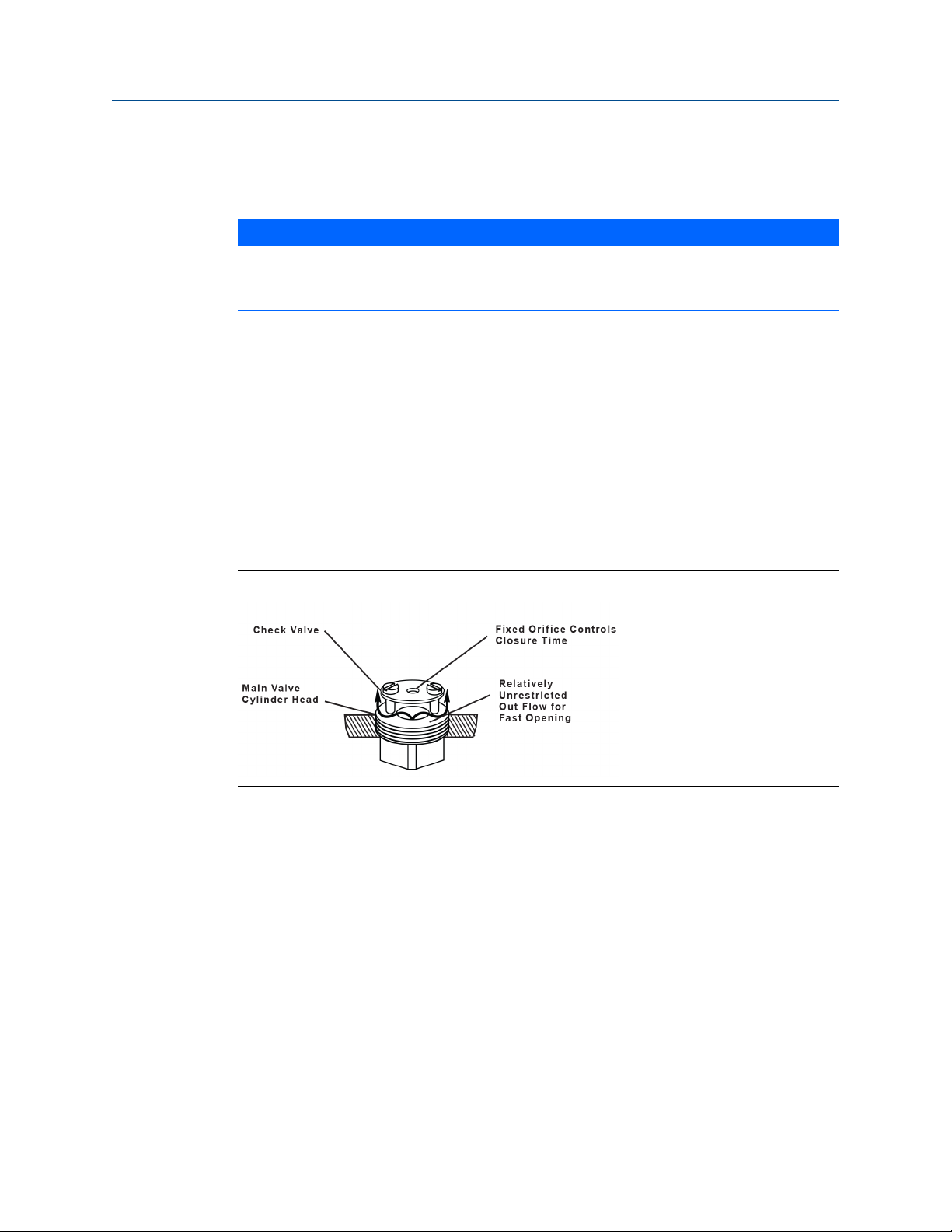
line pressure. Opening and closing speeds are controlled by a check valve mounted to the
internal surface of the cylinder head as shown in Figure 1-1.
Introduction
Check valveFigure 1-1:
Opening speed is relatively unrestricted which results in very fast opening speed. Closing
speed is controlled by the fixed orifice in the check valve.
These valves are normally closed and open on increasing inlet pressure. The basic valve is
the balanced piston design. Nitrogen gas is used to pressurize the valve piston to keep it in
the closed position. The valve incorporates an integral oil reservoir mounted on the
external surface of the cylinder head, which upon installation, is partially filled with a light
oil. Gas under pressure is applied to the reservoir. The pressure of the nitrogen gas, minus
the 4 psi (force of the valve spring) is the effective set point of the valve. When the pipeline
pressure is less than this total force, the valve will be tightly closed. As pipeline pressure
increases the spring and gas pressure is overcome and the valve opens. The oil is a
moveable barrier between the gas and the valve piston. This should eliminate any
possibility of gas permeating the piston seal which would result in gas bypassing the piston
and gas consumption.
The valve may be mounted in a 45° angle position, horizontally or vertically. Whichever
orientation is specified, the oil reservoir must be vertical.
User manual 5
Page 16

Introduction
Valve orientationFigure 1-2:
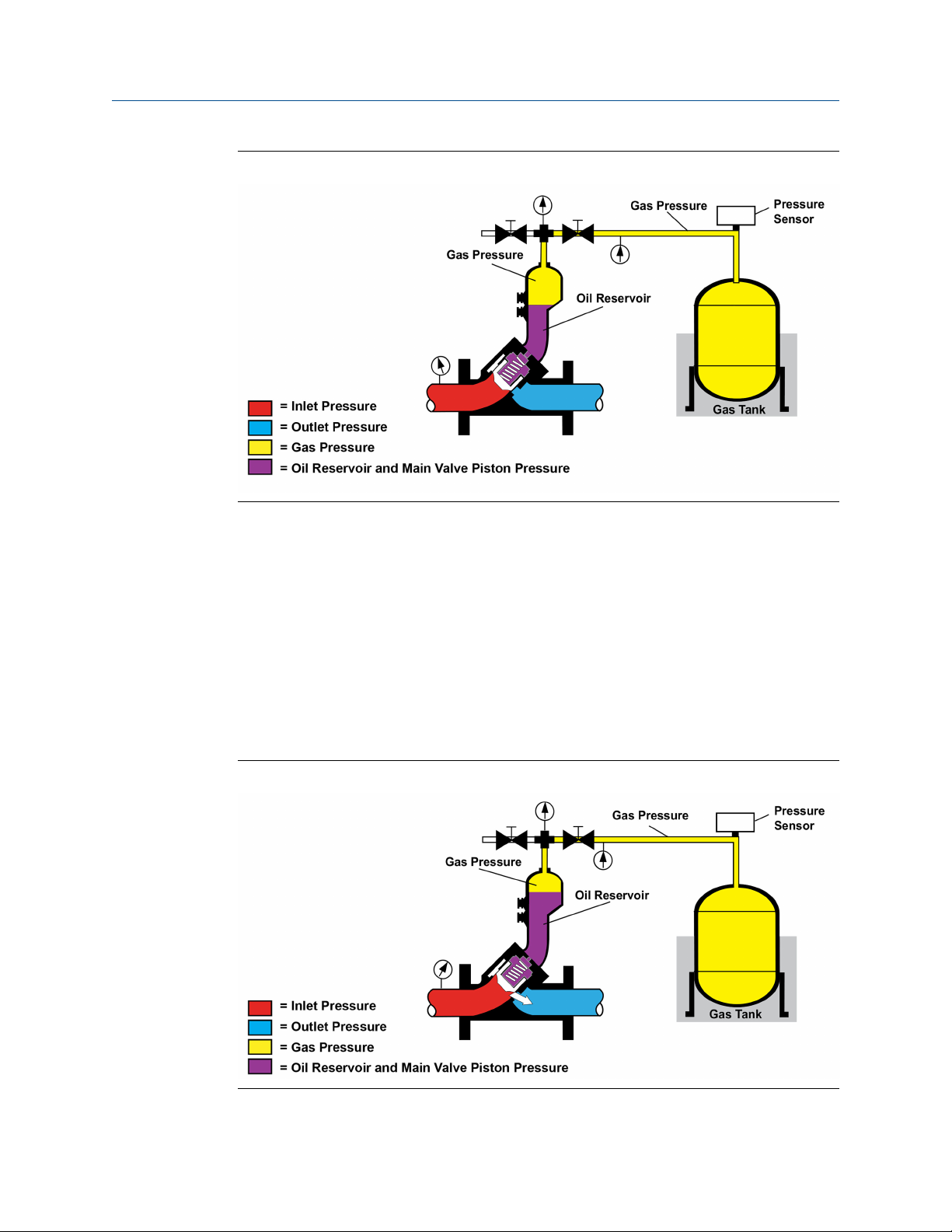
Closed position
Line pressure on the nose of the piston is equally transmitted to the spring side of the
piston. When the nitrogen pressure is applied to the top of the oil, (which is in effect a
moveable barrier between the piston and nitrogen) plus the spring pressure is greater than
line pressure, the valve will be in the closed position. (See below.)
6 Daniel Models 762, 763, 765, 766 and 767 Control Valves
Page 17
Introduction
Closed positionFigure 1-3:
• The oil reservoir is supplied with two sight gauges. When the valve is closed the oil
level in the reservoir will show oil covering the lower sight glass only.
• Oil visible in both the lower and upper sight gauges indicates that the valve is in the
open position.
• Absence of oil in the lower sight gauge indicates that proper oil capacity has not
been reached or that reservoir oil is leaking into the product system. (See below.)
Open position
As pipeline pressure increases, the combined force of the spring and nitrogen gas pressure
is overcome and the valve opens.
Open positionFigure 1-4:
User manual 7
Page 18

Introduction
• Opening and closing speed is controlled by a unique check valve mounted to the
internal surface of the cylinder head. The opening of the valve is relatively
unrestricted, and response time is typically under 100 msec.
• This results in an extremely fast opening response. The opening and closing speeds
are controlled by an orifice in the check valve.
A simple routine visual check can be done to determine if the oil in the sight glass is within
the recommended limits. This makes it easy for a pipeline operations team to be confident
of the surge relief valves readiness.
Note
The spring in the Daniel Nitrogen Loaded Surge Relief Valve is for shipping purposes to ensure piston
movement does not cause damage during shipment. This is the only purpose of this spring.
Note
Equal area on both sides of the piston allow the nitrogen pressure to be set at the actual set point
minus spring force rather than a calculated percentage.
Note
Oil in the reservoir of the Daniel Nitrogen Loaded Surge Relief Valve has many advantages. It allows
the piston seals to be exposed to a clean, lubricant fluid which helps to extend the service life of the
seals tremendously. In addition, it should eliminate the possibility of nitrogen gas permeating the
seals which will ultimately result in a leak and nitrogen consumption.
NOTICE
The Daniel Models do not comply with any internationally over-pressurization protection
recognized codes. What the Daniel Models do is to allow the movement of an undetermined
amount of substance within a pressurized system, not from a pressurized system.
8 Daniel Models 762, 763, 765, 766 and 767 Control Valves
Page 19
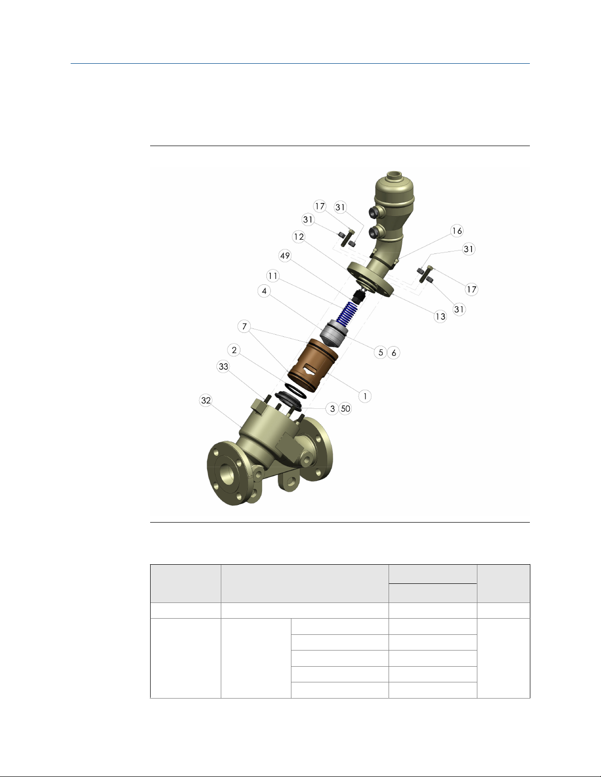
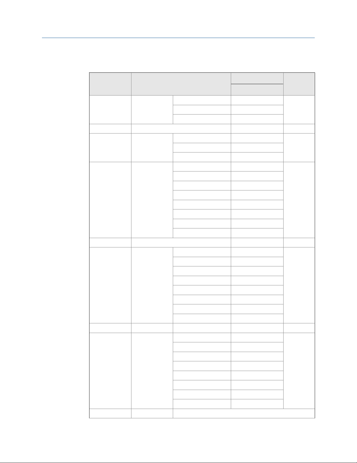
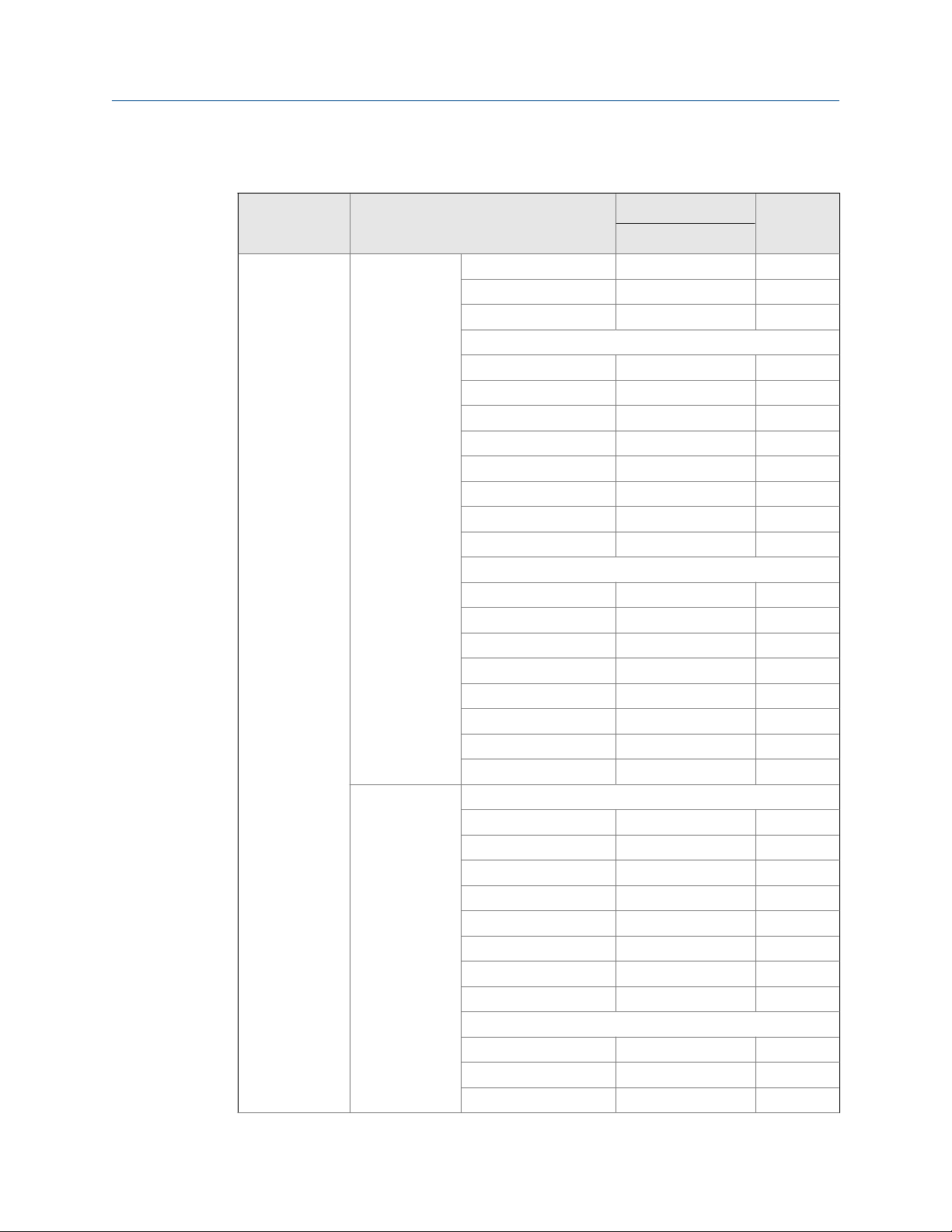
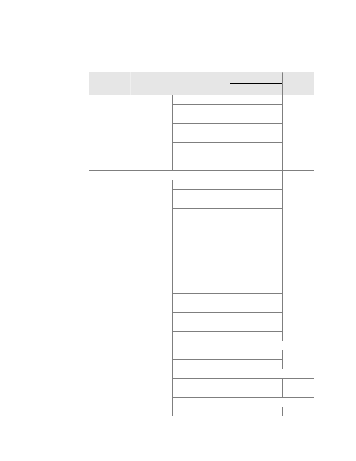
1.2.4 Parts list for the Models 762, 763, 765, 766 and 767 Control Valves
Models 762, 763, 765, 766 and 767 Control Valves NPS 2"-12"Figure 1-5:
Introduction
Table 1-1:
Item number Description
1 Cylinder 526471-690 1
2 O-ring Buna-N 1500399 1
User manual 9
Part description for a model 762, 763, 765, 766 and 767 Control Valve NPS
2
Part number
2 inch
EPR 1500399-005
FFKM 1500399-075
NBR (Low-swell) 1500399-120
CR 1500399-116
Quantity
Page 20
Introduction
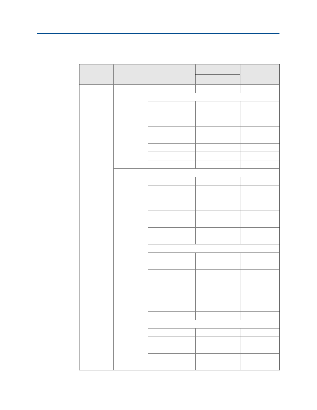
Table 1-1:
Part description for a model 762, 763, 765, 766 and 767 Control Valve NPS
2 (continued)
Part number
Item number Description
FKM 1500399-022
FKM GFLT 1500399-027
FKM V1289 1500399-029
3 Seat ring 526024-610 1
4 Piston Standard 520024-691 1
AP option 520024-693
High-pressure 526024-691
5 O-ring Buna-N 152073 1
EPR 152073-005
FFKM 152073-075
NBR (Low-swell) 152073-120
CR 152073-116
FKM 152073-022
FKM GFLT 152073-027
FKM V1289 152073-029
6 Backup ring 157194 2
7 O-ring Buna-N 157000 2
EPR 157000-005
FFKM 157000-075
NBR (Low-swell) 157000-120
CR 157000-116
FKM 157000-022
FKM GFLT 157000-027
FKM V1289 157000-029
11 Spring Light (blue) 530031 1
12 O-ring Buna-N 157029 1
EPR 157029-005
FFKM 157029-075
NBR (Low-swell) 157029-120
CR 157029-116
FKM 157029-022
FKM GFLT 157029-027
FKM V1289 157029-029
13 Cylinder head Horizontal
2 inch
Quantity
10 Daniel Models 762, 763, 765, 766 and 767 Control Valves
Page 21

Introduction
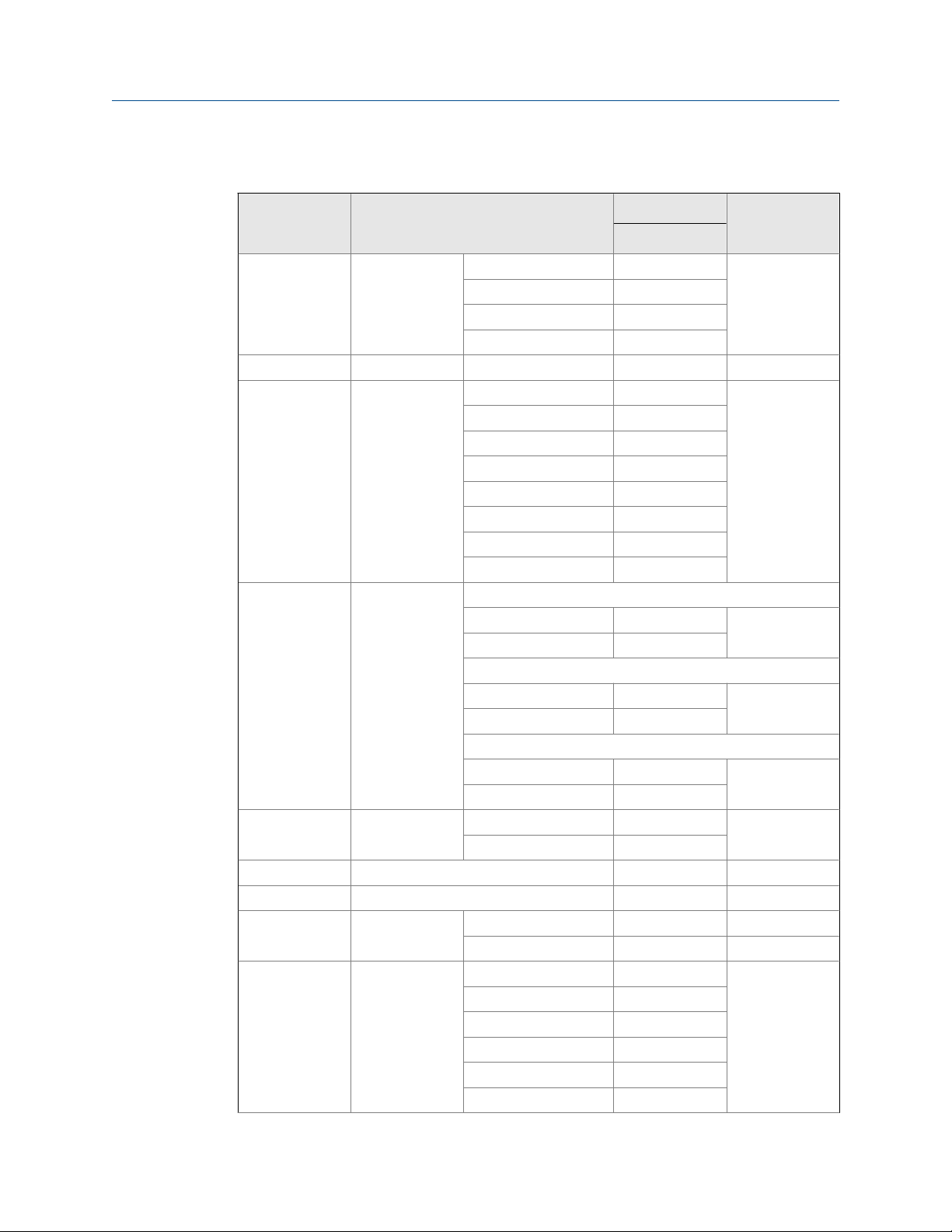
Table 1-1:
Part description for a model 762, 763, 765, 766 and 767 Control Valve NPS
2 (continued)
Part number
Item number Description
Class 150 and 300 520754-590M 1
Class 600 526754-590M
45°
Class 150 and 300 520854-590M 1
Class 600 526854-590M
Vertical
Class 150 and 300 520954-590M 1
Class 600 526954-590M
16 Screw Class 150 and 300 151066M 4
Class 600 151032M 4
17 Jack-out screws 150691 2
27 Bal-seal 159775 2
28 Piston seal retainer 520027-690 2
29 External retaining ring 156576 2
31 Nuts Class 150 and 300 151546M 4
Class 600 151553M 4
32 Valve body Class 150 521001M 1
Class 300 523001M
Class 600 526001M
DIN PN 16 521001-016M
DIN PN 40 523001-040M
DIN PN 64 526001-064M
DIN PN 100 526001-100M
33 Studs Class 150 and 300 151309M 4
Class 600 151451M 4
34 Pipe plug 154721 2
49 Check valve assembly 520045-701 1
50 Set screw 150975 1
A Cylinder
assembly class
150 and 300
Horizontal
Buna-N 520770-690 1
EPR 520770-697 1
FFKM 520770-695 1
NBR (Low-swell) 520770-696 1
CR 520770-693 1
2 inch
Quantity
User manual 11
Page 22
Introduction
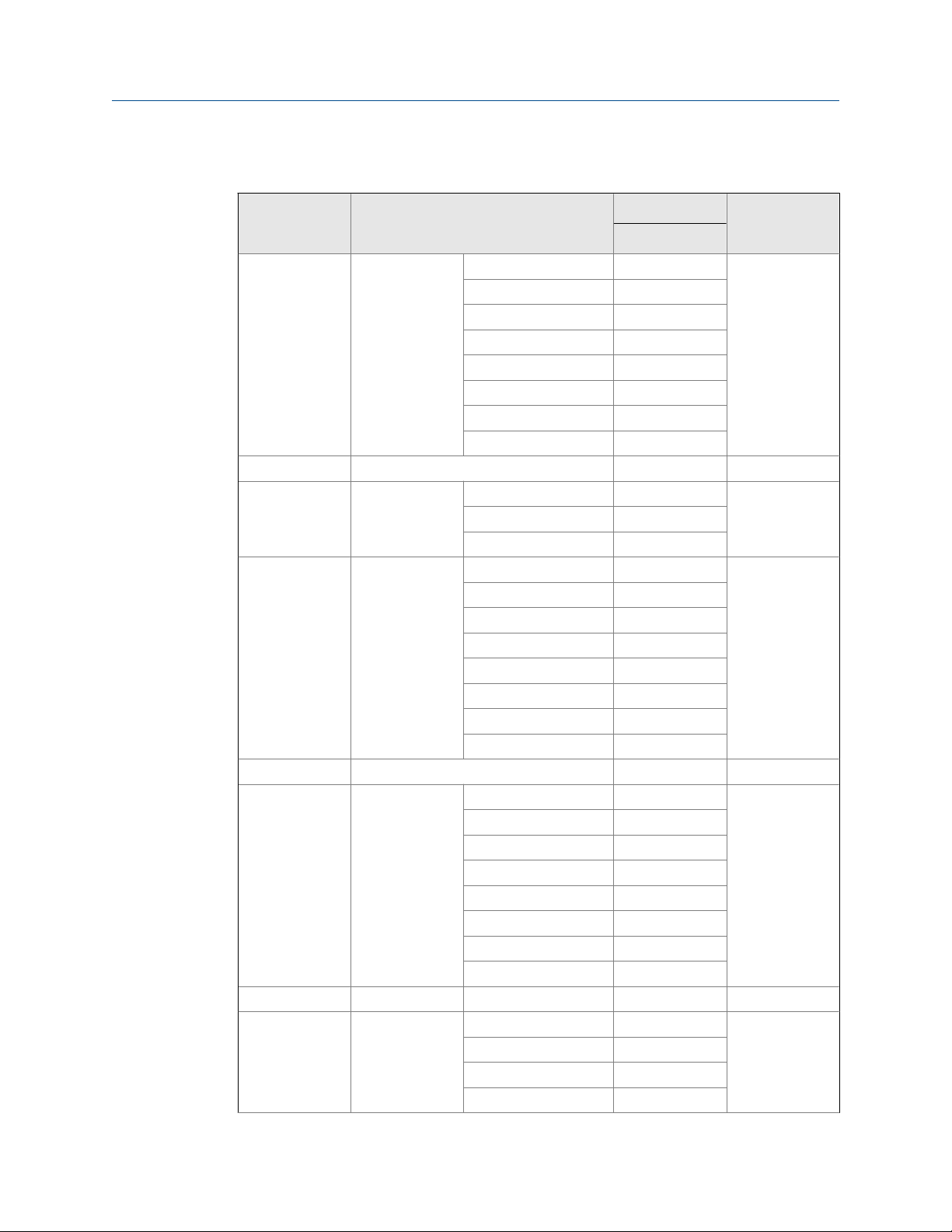
Table 1-1:
Part description for a model 762, 763, 765, 766 and 767 Control Valve NPS
2 (continued)
Item number Description
Cylinder
assembly class
600
Part number
2 inch
FKM 520770-692 1
FKM GFLT 520770-69G 1
FKM V1289 520770-69M 1
45°
Buna-N 520870-690 1
EPR 520870-697 1
FFKM 520870-695 1
NBR (Low-swell) 520870-696 1
CR 520870-693 1
FKM 520870-692 1
FKM GFLT 520870-69G 1
FKM V1289 520870-69M 1
Vertical
Buna-N 520970-690 1
EPR 520970-697 1
FFKM 520970-695 1
NBR (Low-swell) 520970-696 1
CR 520970-693 1
FKM 520970-692 1
FKM GFLT 520970-69G 1
FKM V1289 520970-69M 1
Horizontal
Buna-N 526770-690 1
EPR 526770-697 1
FFKM 526770-695 1
NBR (Low-swell) 526770-696 1
CR 526770-693 1
FKM 526770-692 1
FKM GFLT 526770-69G 1
FKM V1289 52770-69M 1
45°
Buna-N 526870-690 1
EPR 526870-697 1
FFKM 526870-695 1
Quantity
12 Daniel Models 762, 763, 765, 766 and 767 Control Valves
Page 23

Introduction
Table 1-1:
Part description for a model 762, 763, 765, 766 and 767 Control Valve NPS
2 (continued)
Item number Description
Part number
Quantity2 inch
NBR (Low-swell) 526870-696 1
CR 526870-693 1
FKM 526870-692 1
FKM GFLT 526870-69G 1
FKM V1289 526870-69M 1
Vertical
Buna-N 526970-690 1
EPR 526970-697 1
FFKM 526970-695 1
NBR (Low-swell) 526970-696 1
CR 526970-693 1
FKM 526970-692 1
FKM GFLT 526970-69G 1
Table 1-2:
Part description for a model 762, 763, 765, 766 and 767 Control Valve NPS
3
Part number
Item number Description
1 Cylinder 536471-690 1
2 O-ring Buna-N 1500480 1
EPR 1500480-005
FFKM 1500480-075
NBR (Low-swell) 1500480-120
CR 1500480-116
FKM 1500480-022
FKM GFLT 1500480-027
FKM V1289 1500480-029
3 Seat ring 536026-610 1
4 Piston Standard 530024-691 1
AP option 530024-693
High-pressure 536024-691
5 O-ring Buna-N 152075 1
EPR 152075-005
3 inch
Quantity
User manual 13
Page 24

Introduction
Table 1-2:
Part description for a model 762, 763, 765, 766 and 767 Control Valve NPS
3 (continued)
Part number
Item number Description
FFKM 152075-075
NBR (Low-swell) 152075-120
CR 152075-116
FKM 152075-022
FKM GFLT 152075-027
FKM V1289 152075-029
6 Backup ring 157195 2
7 O-ring Buna-N 152095 2
EPR 152095-005
FFKM 152095-075
NBR (Low-swell) 152095-120
CR 152095-116
FKM 152095-022
FKM GFLT 152095-027
FKM V1289 152095-029
11 Spring Light (blue) 540031 1
12 O-ring Buna-N 159575 1
EPR 159575-005
FFKM 159575-075
NBR (Low-swell) 159575-120
CR 159575-116
FKM 159575-022
FKM GFLT 159575-027
FKM V1289 159575-029
13 Cylinder head Horizontal
Standard 530754-590M 1
High-pressure 536754-590M
45°
Standard 530854-590M 1
High-pressure 536854-590M
Vertical
Standard 530954-590M 1
High-pressure 536954-590M
16 Screw Class 150 and 300 151012M 6
3 inch
Quantity
14 Daniel Models 762, 763, 765, 766 and 767 Control Valves
Page 25

Introduction
Table 1-2:
Part description for a model 762, 763, 765, 766 and 767 Control Valve NPS
3 (continued)
Part number
Item number Description
Class 600 151033M 6
17 Jack-out screws 150695 2
27 Bal-seal 159714 2
31 Nuts Class 150 and 300 151547M 4
Class 600 151553M 8
32 Valve body Class 150 531001M 1
Class 300 533001M
Class 600 536001M
DIN PN 16 531001-016M
DIN PN 40 533001-040M
DIN PN 64 536001-064M
DIN PN 100 536001-100M
33 Studs Class 150 and 300 151305M 4
Class 600 151451M 8
34 Pipe plug 154721 2
49 Check valve assembly 530045-701 1
50 Set screw 150975 1
A Cylinder
assembly class
150 and 300
Horizontal
Buna-N 530770-690 1
EPR 530770-697 1
FFKM 530770-695 1
NBR (Low-swell) 530770-696 1
CR 530770-693 1
FKM 530770-692 1
FKM GFLT 530770-69G 1
FKM V1289 530770-69M 1
45°
Buna-N 530870-690 1
EPR 530870-697 1
FFKM 530870-695 1
NBR (Low-swell) 530870-696 1
CR 530870-693 1
FKM 530870-692 1
FKM GFLT 530870-69G 1
3 inch
Quantity
User manual 15
Page 26
Introduction
Table 1-2:
Part description for a model 762, 763, 765, 766 and 767 Control Valve NPS
3 (continued)
Item number Description
Cylinder
assembly class
600
Part number
3 inch
FKM V1289 530870-69M 1
Vertical
Buna-N 530970-690 1
EPR 530970-697 1
FFKM 530970-695 1
NBR (Low-swell) 530970-696 1
CR 530970-693 1
FKM 530970-692 1
FKM GFLT 530970-69G 1
FKM V1289 530970-69M 1
Horizontal
Buna-N 536770-690 1
EPR 536770-697 1
FFKM 536770-695 1
NBR (Low-swell) 536770-696 1
CR 536770-693 1
FKM 536770-692 1
FKM GFLT 53670-69G 1
FKM V1289 536770-69M 1
45°
Buna-N 536870-690 1
EPR 536870-697 1
FFKM 536870-695 1
NBR (Low-swell) 536870-696 1
CR 536870-693 1
FKM 536870-692 1
FKM GFLT 536870-69G 1
FKM V1289 536870-69M 1
Vertical
Buna-N 536970-690 1
EPR 536970-697 1
FFKM 536970-695 1
NBR (Low-swell) 536970-696 1
CR 536970-693 1
Quantity
16 Daniel Models 762, 763, 765, 766 and 767 Control Valves
Page 27

Introduction
Table 1-2:
Part description for a model 762, 763, 765, 766 and 767 Control Valve NPS
3 (continued)
Part number
Item number Description
FKM 536970-692 1
FKM GFLT 536970-69G 1
Table 1-3:
Part description for a model 762, 763, 765, 766 and 767 Control Valve NPS
4
Part number
Item number Description
1 Cylinder 546471-690 1
2 O-ring Buna-N 152080 1
EPR 152080-005
FFKM 152080-075
NBR (Low-swell) 152080-120
CR 152080-116
FKM 152080-022
FKM GFLT 152080-027
FKM V1289 152080-029
3 Seat ring 546026-610 1
4 Piston Standard 540024-691 1
AP option 540024-693
High-pressure 546024-691
5 O-ring Buna-N 152078 1
EPR 152078-005
FFKM 152078-075
NBR (Low-swell) 152078-120
CR 152078-116
FKM 152078-022
FKM GFLT 152078-027
FKM V1289 152078-029
6 Backup ring 157196 2
7 O-ring Buna-N 152094 2
EPR 152094-005
FFKM 152094-075
NBR (Low-swell) 152094-120
4 inch
Quantity3 inch
Quantity
User manual 17
Page 28
Introduction
Table 1-3:
Part description for a model 762, 763, 765, 766 and 767 Control Valve NPS
4 (continued)
Part number
Item number Description
CR 152094-116
FKM 152094-022
FKM GFLT 152094-027
FKM V1289 152094-029
11 Spring Light (blue) 540031 1
12 O-ring Buna-N 157032 1
EPR 157032-005
FFKM 157032-075
NBR (Low-swell) 157032-120
CR 157032-116
FKM 157032-022
FKM GFLT 152078-027
FKM V1289 152078-029
13 Cylinder head Horizontal
Standard 540754-590M 1
High-pressure 546754-590M
45°
Standard 540854-590M 1
High-pressure 546854-590M
Vertical
Standard 540954-590M 1
High-pressure 546954-590M
16 Screw Class 150 and 300 151012M 6
Class 600 151033M
17 Jack-out screws 150695 2
27 Bal-seal 159715 2
31 Nuts Class 150 and 300 151547M 6
Class 600 151551M 8
32 Valve body Class 150 541001M 1
Class 300 543001M
Class 600 546001M
DIN PN 16 541001-016M
DIN PN 40 543001-040M
DIN PN 64 546001-064M
4 inch
Quantity
18 Daniel Models 762, 763, 765, 766 and 767 Control Valves
Page 29

Introduction
Table 1-3:
Part description for a model 762, 763, 765, 766 and 767 Control Valve NPS
4 (continued)
Part number
Item number Description
DIN PN 100 546001-100M
33 Studs Class 150 and 300 151305M 6
Class 600 151454M 8
34 Pipe plug Class 150 and 300 154721M 2
Class 600 154704M
49 Check valve assembly 540045-701 1
50 Set screw 150975 1
A Cylinder
assembly class
150 and 300
Horizontal
Buna-N 540770-690 1
EPR 540770-697 1
FFKM 540770-695 1
NBR (Low-swell) 540770-696 1
CR 540770-693 1
FKM 540770-692 1
FKM GFLT 540770-69G 1
FKM V1289 540770-69M 1
45°
Buna-N 540870-690 1
EPR 540870-697 1
FFKM 540870-695 1
NBR (Low-swell) 540870-696 1
CR 540870-693 1
FKM 540870-692 1
FKM GFLT 540870-69G 1
FKM V1289 540870-69M 1
Vertical
Buna-N 540970-690 1
EPR 540970-697 1
FFKM 540970-695 1
NBR (Low-swell) 540970-696 1
CR 540970-693 1
FKM 540970-692 1
FKM GFLT 540970-69G 1
FKM V1289 540970-69M 1
4 inch
Quantity
User manual 19
Page 30

Introduction
Table 1-3:
Part description for a model 762, 763, 765, 766 and 767 Control Valve NPS
4 (continued)
Item number Description
Cylinder
assembly class
600
Part number
Quantity4 inch
Horizontal
Buna-N 546770-690 1
EPR 546770-697 1
FFKM 546770-695 1
NBR (Low-swell) 546770-696 1
CR 546770-693 1
FKM 546770-692 1
FKM GFLT 546770-69G 1
FKM V1289 546770-69M 1
45°
Buna-N 546870-690 1
EPR 546870-697 1
FFKM 546870-695 1
NBR (Low-swell) 546870-696 1
CR 546870-693 1
FKM 546870-692 1
FKM GFLT 54670-69G 1
FKM V1289 546870-69M 1
Vertical
Buna-N 546970-690 1
EPR 546970-697 1
FFKM 546970-695 1
NBR (Low-swell) 546970-696 1
CR 546970-693 1
FKM 546970-692 1
FKM GFLT 546970-69G 1
FKM V1289 546970-69M 1
Table 1-4:
Part description for a model 762, 763, 765, 766 and 767 Control Valve NPS
6
Part number
Item number Description
1 Cylinder 566471-590 1
6 inch
Quantity
20 Daniel Models 762, 763, 765, 766 and 767 Control Valves
Page 31
Introduction
Table 1-4:
Part description for a model 762, 763, 765, 766 and 767 Control Valve NPS
6 (continued)
Part number
Item number Description
2 O-ring Buna-N 1500407 1
EPR 1500407-005
FFKM 1500407-075
NBR (Low-swell) 1500407-120
CR 1500407-116
FKM 1500407-022
FKM GFLT 1500407-027
FKM V1289 1500407-029
3 Seat ring 566026-610 1
4 Piston Standard 560024-691 1
AP option 560024-693
High-pressure 566024-691
5 O-ring Buna-N 157002 1
EPR 157002-005
FFKM 157002-075
NBR (Low-swell) 157002-120
CR 157002-116
FKM 157002-022
FKM GFLT 157002-027
FKM V1289 157002-029
6 Backup ring 157197 2
7 O-ring Buna-N 152079 2
EPR 152079-005
FFKM 152079-075
NBR (Low-swell) 152079-120
CR 152079-116
FKM 152079-022
FKM GFLT 152079-027
FKM V1289 152079-029
11 Spring Light (blue) 560031 1
12 O-ring Buna-N 159576 1
EPR 159576-005
FFKM 159576-075
NBR (Low-swell) 159576-120
6 inch
Quantity
User manual 21
Page 32

Introduction
Table 1-4:
Part description for a model 762, 763, 765, 766 and 767 Control Valve NPS
6 (continued)
Part number
Item number Description
CR 159576-116
FKM 159576-022
FKM GFLT 159576-027
FKM V1289 159576-029
13 Cylinder head Horizontal
Standard 560754-590M 1
High-pressure 566754-590M
45°
Standard 560854-590M 1
High-pressure 566854-590M
Vertical
Standard 560954-590M 1
High-pressure 566954-590M
16 Screw Class 150 and 300 151012M 8
Class 600 151068M 8
17 Jack-out screws 150695 2
27 Bal-seal 159716 2
31 Nuts Class 150 and 300 151553M 8
Class 600 151558M 8
32 Valve body Class 150 561001M 1
Class 300 563001M
Class 600 566001M
DIN PN 16 561001-016M
DIN PN 40 563001-040M
DIN PN 64 566001-064M
DIN PN 100 566001-100M
33 Studs Class 150 and 300 151347M 8
Class 600 151450M 8
34 Pipe plug Class 150 and 300 154721M 2
Class 600 154704M 2
49 Check valve assembly 560045-701 1
50 Set screw 150975 1
A Cylinder Horizontal
Buna-N 560770-690 1
6 inch
Quantity
22 Daniel Models 762, 763, 765, 766 and 767 Control Valves
Page 33

Introduction
Table 1-4:
Part description for a model 762, 763, 765, 766 and 767 Control Valve NPS
6 (continued)
Item number Description
assembly class
150 and 300
Cylinder
assembly class
600
Part number
6 inch
EPR 560770-697 1
FFKM 560770-695 1
NBR (Low-swell) 560770-696 1
CR 560770-693 1
FKM 560770-692 1
FKM GFLT 560770-69G 1
FKM V1289 560770-69M 1
45°
Buna-N 560870-690 1
EPR 560870-697 1
FFKM 560870-695 1
NBR (Low-swell) 560870-696 1
CR 560870-693 1
FKM 560870-692 1
FKM GFLT 560870-69G 1
FKM V1289 560870-69M 1
Vertical
Buna-N 560970-690 1
EPR 560970-697 1
FFKM 560970-695 1
NBR (Low-swell) 560970-696 1
CR 560970-693 1
FKM 560970-692 1
FKM GFLT 560970-69G 1
FKM V1289 560970-69M 1
Horizontal
Buna-N 566770-690 1
EPR 566770-697 1
FFKM 566770-695 1
NBR (Low-swell) 566770-696 1
CR 566770-693 1
FKM 566770-692 1
FKM GFLT 566770-69G 1
FKM V1289 566770-69M 1
Quantity
User manual 23
Page 34

Introduction
Table 1-4:
Part description for a model 762, 763, 765, 766 and 767 Control Valve NPS
6 (continued)
Item number Description
Part number
Quantity6 inch
45°
Buna-N 566870-690 1
EPR 566870-697 1
FFKM 566870-695 1
NBR (Low-swell) 566870-696 1
CR 566870-693 1
FKM 566870-692 1
FKM GFLT 566870-69G 1
FKM V1289 566870-69M 1
Vertical
Buna-N 566970-690 1
EPR 566970-697 1
FFKM 566970-695 1
NBR (Low-swell) 566970-696 1
CR 566970-693 1
FKM 566970-692 1
FKM GFLT 566970-69G 1
FKM V1289 566970-69M 1
Table 1-5:
Part description for a model 762, 763, 765, 766 and 767 Control Valve NPS
8
Part number
Item number Description
1 Cylinder 586471-500 1
2 O-ring Buna-N 157006 1
EPR 157006-005
FFKM 157006-075
NBR (Low-swell) 157006-120
CR 157006-116
FKM 157006-022
FKM GFLT 157006-027
FKM V1289 157006-029
3 Seat ring 586026-600 1
8 inch
Quantity
24 Daniel Models 762, 763, 765, 766 and 767 Control Valves
Page 35

Introduction
Table 1-5:
Part description for a model 762, 763, 765, 766 and 767 Control Valve NPS
8 (continued)
Part number
Item number Description
4 Piston Standard 580057-601 1
AP option 580057-630
High-pressure 586057-601
5 O-ring Buna-N 157005 1
EPR 157005-005
FFKM 157005-075
NBR (Low-swell) 157005-120
CR 157005-116
FKM 157005-022
FKM GFLT 157005-027
FKM V1289 157005-029
6 Backup ring 157198 2
7 O-ring Buna-N 157004 2
EPR 157004-005
FFKM 157004-075
Low-swell NBR 157004-120
CR 157004-116
FKM 157004-022
FKM GFLT 157004-027
FKM V1289 157004-029
11 Spring Light (blue) 580031 1
12 O-ring Buna-N 157074 1
EPR 157074-005
FFKM 157074-075
NBR (Low-swell) 157074-120
CR 157074-116
FKM 157074-022
FKM GFLT 157074-027
FKM V1289 157074-029
13 Cylinder head Horizontal
Standard 580754-590M 1
High-pressure 586754-590M
45°
Standard 580854-590M 1
8 inch
Quantity
User manual 25
Page 36

Introduction
Table 1-5:
Part description for a model 762, 763, 765, 766 and 767 Control Valve NPS
8 (continued)
Part number
Item number Description
High-pressure 586854-590M
Vertical
Standard 580954-590M 1
High-pressure 586954-590M
16 Screw Standard 151072 4
High-pressure 151038 4
17 Jack-out screws 150696 2
27 Bal-seal 159651 2
31 Nuts Class 150 and 300 151558M 4
Class 600 151559M 4
32 Valve body Class 150 581008M 1
Class 300 583001M
Class 600 586001M
DIN PN 16 581001-016M
DIN PN 40 583001-040M
DIN PN 64 586001-064M
DIN PN 100 586001-100M
33 Studs Class 150 and 300 151335M 4
Class 600 151455M 4
34 Pipe plug 154704M 2
49 Check valve assembly 580045-701 1
50 Set screw 150975-019 1
A Cylinder
assembly class
150 and 300
Horizontal
Buna-N 580770-690 1
EPR 580770-697 1
FFKM 580770-695 1
NBR (Low-swell) 580770-696 1
CR 580770-693 1
FKM 580770-692 1
FKM GFLT 580770-69G 1
FKM V1289 580770-69M 1
45°
Buna-N 580870-690 1
EPR 580870-697 1
8 inch
Quantity
26 Daniel Models 762, 763, 765, 766 and 767 Control Valves
Page 37

Introduction
Table 1-5:
Part description for a model 762, 763, 765, 766 and 767 Control Valve NPS
8 (continued)
Item number Description
Cylinder
assembly class
600
Part number
8 inch
FFKM 580870-695 1
NBR (Low-swell) 580870-696 1
CR 580870-693 1
FKM 580870-692 1
FKM GFLT 580870-69G 1
FKM V1289 580870-69M 1
Vertical
Buna-N 580970-690 1
EPR 580970-697 1
FFKM 580970-695 1
NBR (Low-swell) 580970-696 1
CR 580970-693 1
FKM 580970-692 1
FKM GFLT 50970-69G 1
FKM V1289 580970-69M 1
Horizontal
Buna-N 586770-690 1
EPR 586770-697 1
FFKM 586770-695
NBR (Low-swell) 586770-696
CR 586770-693
FKM 586770-692
FKM GFLT 586770-69G 1
FKM V1289 586770-69M 1
45°
Buna-N 586870-690 1
EPR 586870-697 1
FFKM 586870-695 1
NBR (Low-swell) 586870-696 1
CR 586870-693 1
FKM 586870-692 1
FKM GFLT 586870-69G 1
FKM V1289 586870-69M 1
Vertical
Quantity
User manual 27
Page 38

Introduction
Table 1-5:
Part description for a model 762, 763, 765, 766 and 767 Control Valve NPS
8 (continued)
Part number
Item number Description
Buna-N 586970-690 1
EPR 586970-697 1
FFKM 58970-695 1
NBR (Low-swell) 586970-696 1
CR 586970-693 1
FKM 586970-692 1
FKM GFLT 586970-69G 1
FKM V1289 586970-69M 1
Table 1-6:
Part description for a model 762, 763, 765, 766 and 767 Control Valve NPS
10
Part number
Item number Description
1 Cylinder 606471-510 1
2 O-ring Buna-N 157014 1
EPR 157014-005
FFKM 157014-075
NBR (Low-swell) 157014-120
CR 157014-116
FKM 157014-022
FKM GFLT 157014-027
FKM V1289 157014-029
3 Seat ring 606026-600 1
4 Piston Standard
Buna-N 600057-600 1
FFKM 600057-608
NBR (Low-swell) 600057-60L
CR 600057-603
FKM 600057-602
AP option 600057-631 1
High-pressure
Buna-N 606057-600 1
FKM 606057-602
10 inch
Quantity8 inch
Quantity
28 Daniel Models 762, 763, 765, 766 and 767 Control Valves
Page 39
Introduction
Table 1-6:
Part description for a model 762, 763, 765, 766 and 767 Control Valve NPS
10 (continued)
Part number
Item number Description
5 O-ring Buna-N 157015 1
EPR 157015-005
FFKM 157015-075
NBR (Low-swell) 157015-120
CR 157015-116
FKM 157015-022
FKM GFLT 157015-027
FKM V1289 157015-029
6 Backup ring 157190 2
7 O-ring Buna-N 157013 2
EPR 157013-005
FFKM 157013-075
NBR (Low-swell) 157013-120
CR 157013-116
FKM 157013-022
FKM GFLT 157013-027
FKM V1289 157013-029
11 Spring Light (blue) 600031 1
12 O-ring Buna-N 157340 1
EPR 157340-005
FFKM 157340-075
NBR (Low-swell) 157340-120
CR 157340-116
FKM 157340-022
FKM GFLT 157340-027
FKM V1289 157340-029
13 Cylinder head Horizontal
Standard 600754-510M 1
High-pressure 606754-590M
45°
Standard 600854-590M 1
High-pressure 606854-590M
Vertical
Standard 600954-590M 1
10 inch
Quantity
User manual 29
Page 40

Introduction
Table 1-6:
Part description for a model 762, 763, 765, 766 and 767 Control Valve NPS
10 (continued)
Part number
Item number Description
High-pressure 606954-590M
16 Screw Standard 151017M 4
High-pressure 151026M 4
17 Jack-out screws 150698 2
27 Bal-seal 159805 2
31 Nuts Class 150 and 300 151559M 4
Class 600 151560M 4
32 Valve body Class 150 601001M 1
Class 300 603001M
Class 600 606001M
DIN PN 16 601001-016M
DIN PN 40 603001-040M
DIN PN 64 606001-064M
DIN PN 100 606001-100M
33 Studs Class 150 and 300 151345M 4
Class 600 151456M 4
34 Pipe plug 154704M 2
49 Check valve assembly 600045-701 1
50 Set screw 150977-019 1
A Cylinder
assembly class
150 and 300
Horizontal
Buna-N 600770-690 1
EPR 600770-697 1
FFKM 600770-695 1
NBR (Low-swell) 600770-696 1
CR 600770-693 1
FKM 600770-692 1
FKM GFLT 600770-69G 1
FKM V1289 600770-69M 1
45°
Buna-N 600870-690 1
EPR 600870-697 1
FFKM 600870-695 1
NBR (Low-swell) 600870-696 1
CR 600870-693 1
10 inch
Quantity
30 Daniel Models 762, 763, 765, 766 and 767 Control Valves
Page 41

Introduction
Table 1-6:
Part description for a model 762, 763, 765, 766 and 767 Control Valve NPS
10 (continued)
Item number Description
Cylinder
assembly class
600
Part number
10 inch
FKM 600870-692 1
FKM GFLT 600870-69G 1
FKM V1289 600870-69M 1
Vertical
Buna-N 600970-690 1
EPR 600970-697 1
FFKM 600970-695 1
NBR (Low-swell) 600970-696 1
CR 600970-693 1
FKM 600970-692 1
FKM GFLT 60970-69G 1
FKM V1289 600970-69M 1
Horizontal
Buna-N 606770-690 1
EPR 606770-697 1
FFKM 606770-695 1
NBR (Low-swell) 606770-696 1
CR 606770-693 1
FKM 606770-692 1
FKM GFLT 606770-69G 1
FKM V1289 606770-69M 1
45°
Buna-N 606870-690 1
EPR 606870-697 1
FFKM 606870-695 1
NBR (Low-swell) 606870-696 1
CR 606870-693 1
FKM 606870-692 1
FKM GFLT 606870-69G 1
FKM V1289 606870-69M 1
Vertical
Buna-N 606970-690 1
EPR 606970-697 1
FFKM 60970-695 1
Quantity
User manual 31
Page 42

Introduction
Table 1-6:
Part description for a model 762, 763, 765, 766 and 767 Control Valve NPS
10 (continued)
Part number
Item number Description
NBR (Low-swell) 606970-696 1
CR 606970-693 1
FKM 606970-692 1
FKM GFLT 606970-69G 1
FKM V1289 606970-69M 1
Table 1-7:
Part description for a model 762, 763, 765, 766 and 767 Control Valve NPS
12
Part number
Item number Description
1 Cylinder 626471-500 1
2 O-ring Buna-N 157017 1
EPR 157017-005
FFKM 157017-075
NBR (Low-swell) 157017-120
CR 157017-116
FKM 157017-022
FKM GFLT 157017-027
FKM V1289 157017-029
3 Seat ring 626026-600 1
4 Piston Standard
Buna-N 620057-600 1
FKM 620057-602
FKM V1289 620057-6M
AP 620057-630 1
High-pressure
FKM 626057-602 1
FKM V1289 626057-60M
5 O-ring Buna-N 157018 1
EPR 157018-005
FFKM 157018-075
NBR (Low-swell) 157018-120
CR 157018-116
12 inch
Quantity10 inch
Quantity
32 Daniel Models 762, 763, 765, 766 and 767 Control Valves
Page 43

Introduction
Table 1-7:
Part description for a model 762, 763, 765, 766 and 767 Control Valve NPS
12 (continued)
Part number
Item number Description
FKM 157018-022
FKM GFLT 157018-027
FKM V1289 157018-029
6 Backup ring 157172 2
7 O-ring Buna-N 157019 2
EPR 157019-005
FFKM 157019-075
NBR (Low-swell) 157019-120
CR 157019-116
FKM 157019-022
FKM GFLT 157019-027
FKM V1289 157019-029
11 Spring Light (blue) 620031 1
Medium (bronze) 620029
Heavy (green) 620059-012 1
12 O-ring Buna-N 157030 1
EPR 157030-005
FFKM 157030-075
NBR (Low-swell) 157030-120
CR 157030-116
FKM 157030-022
FKM GFLT 157030-027
FKM V1289 157030-029
13 Cylinder head Horizontal
Standard 620754-590M 1
High-pressure 626754-590M
45°
Standard 620854-590M 1
High-pressure 626854-590M
Vertical
Standard 620954-590M 1
High-pressure 626954-590M
16 Screw Standard 151052M 4
12 inch
620059-018
Quantity
User manual 33
Page 44
Introduction
Table 1-7:
Part description for a model 762, 763, 765, 766 and 767 Control Valve NPS
12 (continued)
Part number
Item number Description
High-pressure 151074M 4
17 Jack-out screws 150697 2
31 Nuts Class 150 and 300 151060M 4
Class 600 151561M 4
32 Valve body Class 150 621001M 1
Class 300 623001M
Class 600 626001M
DIN PN 16 621001-016M
DIN PN 40 623001-040M
DIN PN 64 626001-064M
DIN PN 100 626001-100M
33 Studs Class 150 and 300 151395M 4
Class 600 151457M 4
34 Pipe plug 154704M 2
49 Check valve assembly 620045-701 1
50 Set screw 150977-019 1
A Cylinder
assembly class
150 and 300
Horizontal
Buna-N 620770-690 1
EPR 620770-697 1
FFKM 620770-695 1
NBR (Low-swell) 620770-696 1
CR 620770-693 1
FKM 620770-692 1
FKM GFLT 620770-69G 1
FKM V1289 620770-69M 1
45
Buna-N 620870-690 1
EPR 620870-697 1
FFKM 620870-695 1
NBR (Low-swell) 620870-696 1
CR 620870-693 1
FKM 620870-692 1
FKM GFLT 620870-69G 1
FKM V1289 620870-69M 1
12 inch
Quantity
34 Daniel Models 762, 763, 765, 766 and 767 Control Valves
Page 45

Introduction
Table 1-7:
Part description for a model 762, 763, 765, 766 and 767 Control Valve NPS
12 (continued)
Item number Description
Cylinder
assembly class
600
Part number
12 inch
Vertical
Buna-N 620970-690 1
EPR 620970-697 1
FFKM 620970-695 1
NBR (Low-swell) 620970-696 1
CR 620970-693 1
FKM 620970-692 1
FKM GFLT 62970-69G 1
FKM V1289 620970-69M 1
Horizontal
Buna-N 626770-690 1
EPR 626770-697 1
FFKM 626770-695 1
NBR (Low-swell) 626770-696 1
CR 626770-693 1
FKM 626770-692 1
FKM GFLT 626770-69G 1
FKM V1289 626770-69M 1
45°
Buna-N 626870-690 1
EPR 626870-697 1
FFKM 626870-695 1
NBR (Low-swell) 626870-696 1
CR 626870-693 1
FKM 626870-692 1
FKM GFLT 626870-69G 1
FKM V1289 626870-69M 1
Vertical
Buna-N 626970-690 1
EPR 626970-697 1
FFKM 62970-695 1
NBR (Low-swell) 626970-696 1
CR 626970-693 1
FKM 626970-692 1
Quantity
User manual 35
Page 46

Introduction
Table 1-7:
Part description for a model 762, 763, 765, 766 and 767 Control Valve NPS
12 (continued)
Item number Description
Part number
Quantity12 inch
FKM GFLT 626970-69G 1
FKM V1289 62970-69M 1
36 Daniel Models 762, 763, 765, 766 and 767 Control Valves
Page 47

Introduction
Models 762, 763, 765, 766 and 767 Control Valves NPS 16"Figure 1-6:
User manual 37
Page 48

Introduction
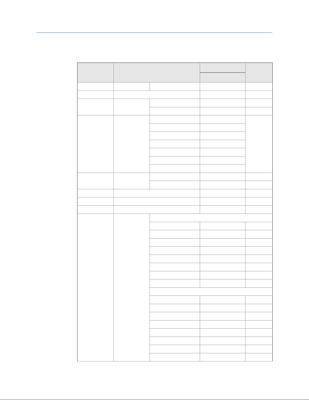
Table 1-8:
Part description for a model 762, 763, 765, 766 and 767 Control Valve NPS
16
Part number
Item number Description
1 Cylinder 666021-500 1
2 O-ring Buna-N 157095 2
EPR 157095-005
FFKM 157095-075
NBR (Low-swell) 157095-120
CR 157095-116
FKM 157095-022
FKM GFLT 157095-027
FKM V1289 157095-029
3 Seat ring 666026-500 1
4 Piston Standard 660124-600 1
AP Consult factory
High-pressure 666057-601
5 O-ring Buna-N 157086 1
EPR 157086-005
FFKM 157086-075
NBR (Low-swell) 157086-120
CR 157086-116
FKM 157086-022
FKM GFLT 157086-027
FKM V1289 157086-029
6 Backup ring 157201 2
7 O-ring Buna-N 157087 2
EPR 157087-005
FFKM 157087-075
NBR (Low-swell) 157087-120
CR 157087-116
FKM 157087-022
FKM GFLT 157087-027
FKM V1289 157087-029
11 Spring Light (blue) 660031 1
13 Cylinder head Standard 660754-500 1
High-pressure 666754-500
16 Screw 151019 24
16 inch
Quantity
38 Daniel Models 762, 763, 765, 766 and 767 Control Valves
Page 49

Introduction
Table 1-8:
Part description for a model 762, 763, 765, 766 and 767 Control Valve NPS
16 (continued)
Part number
Item number Description
17 Jack-out screws Standard 151453-100M 2
High pressure 151399-100M
31 Nuts Class 150 and 300 151560M 4
Class 600 151563M 4
32 Valve body Class 150 661001M 1
Class 300 663001M
Class 600 666001M
DIN PN 16 661001-016M
DIN PN 40 663001-040M
DIN PN 64 666001-064M
DIN PN 100 666001-100M
33 Studs Class 150 and 300 151453M 4
Class 600 151399M 4
34 Pipe plug Standard 154704M 2
High pressure 154718-074M
38 Cap plug 154774 1
39 Check valve 620043-701 1
A Cylinder
assembly class
150 and 300
Cylinder
assembly class
600
Horizontal
Buna-N 660770-690 1
EPR 660770-697 1
FFKM 660770-695 1
NBR (Low-swell) 660770-696 1
CR 660770-693 1
FKM 660770-692 1
FKM GFLT 660770-69G 1
FKM V1289 660770-69M
Buna-N 660870-690 1
EPR 660870-697 1
FFKM 660870-695 1
NBR (Low-swell) 660870-696 1
CR 660870-693 1
FKM 660870-692 1
FKM GFLT 660870-69G 1
FKM V1289 660870-69M 1
16 inch
Quantity
User manual 39
Page 50

Introduction
Table 1-8:
Part description for a model 762, 763, 765, 766 and 767 Control Valve NPS
16 (continued)
Item number Description
Part number
16 inch
Vertical
Buna-N 660970-690 1
EPR 660970-697 1
FFKM 660970-695 1
NBR (Low-swell) 660970-696 1
CR 660970-693 1
FKM 660970-692 1
FKM GFLT 66970-69G 1
FKM V1289 660970-69M 1
Horizontal
Buna-N 666770-690 1
EPR 666770-697 1
FFKM 666770-695 1
NBR (Low-swell) 666770-696 1
CR 666770-693 1
FKM 666770-692 1
FKM GFLT 666770-69G 1
FKM V1289 666770-69M 1
45°
Buna-N 666870-690 1
EPR 666870-697 1
FFKM 666870-695 1
NBR (Low-swell) 666870-696 1
CR 666870-693 1
FKM 666870-692 1
FKM GFLT 666870-69G 1
FKM V1289 666870-69M 1
Vertical
Buna-N 666970-690 1
EPR 666970-697 1
FFKM 66970-695 1
NBR (Low-swell) 666970-696 1
CR 666970-693 1
FKM 666970-692 1
Quantity
40 Daniel Models 762, 763, 765, 766 and 767 Control Valves
Page 51
Introduction
Table 1-8:
Item number Description
Part description for a model 762, 763, 765, 766 and 767 Control Valve NPS
16 (continued)
Part number
Quantity16 inch
FKM GFLT 66970-69G 1
FKM V1289 66970-69M 1
1.3 Agency certifications for the Models 762, 763, 765, 766 and 767 Control Valves
The following product agency certifications are applicable to the Daniel Control Valves.
Agency certifications for control valvesTable 1-9:
Certification type Description
Pressure equipment PED
NOTICE
The Daniel Models do not comply with any internationally over-pressurization protection
recognized codes. What the Daniel Models do is to allow the movement of an undetermined
amount of substance within a pressurized system, not from a pressurized system.
User manual 41
Page 52

Introduction
42 Daniel Models 762, 763, 765, 766 and 767 Control Valves
Page 53

Operating conditions and specifications
2 Operating conditions and
specifications
Topics covered in this chapter:
• Operating conditions for the control valve
• Specifications for the control valve
2.1 Operating conditions for the control valve
Operating conditions for the control valveTable 2-1:
Condition type Description
Fluid phase Liquid
Process temperature -26°C to 205°C (-15°F to 400°F)
Optional process temperature
Fluid velocity Operational recommended flow velocity up to 58 ft/sec, beyond this
Fluid(s) controlled • Low/Medium viscosity crude oils and condensates
Viscosity limits on valves • Maximum valve viscosity is 8800 Cst
Differential pressure The maximum allowable differential pressure across a control valve is
Atmospheric pressure Absolute
Sizes (NPS) 2, 3, 4, 6, 8,10,12,16
Pressure class (ANSI) 150, 300, 600
Maximum safe working
temperature range
-46°C to 205°C (-51°F to 400°F)
point will result in a high pressure drop and increased wear.
• Refined products and intermediates (ie: gasoline, diesel, kerosene,
light fuel oils, jet fuel, LPG, butanes, naphtha, alkylate, reformate,
straight run gasoline, cat-cracked gasoline)
• Petrochemicals (ie: benzene, toluene, xylenes, cumene, olefins, py-
rolysis gasoline)
• Natural gas liquids
• Maximum viscosity for valves with pilots is 440 Cst due to re-
sponse time of high viscosity pilot
6894 kPa (1,000 psi). Consult factory for location of first shut down
valve.
• -26°C to 205°C (-15°F to 400°F)
• Using FKM O-rings
• Temperature range is dependent of O-ring T
• Consult the factory for other safe working temperatures
min
and T
max
User manual 43
Page 54

Operating conditions and specifications
Condition type Description
Maximum safe working
pressure
Materials of construction Main valve body: Steel, ASTM-A352 Gr. LCC
Valve capacity Cv is a capacity coefficient that defines as the number of US gpm of
Operating conditions for the control valve (continued)Table 2-1:
Flange connections/Ratings (DIN) for valve sizes DN50 and DN400:
• DIN PN16 MWP at 120°C: 16 bar
• DIN PN25 MWP at 120°C: 25 bar
• DIN PN40 MWP at 120°C: 40 bar
• DIN PN64 (class 300) MWP at 120°C: 51 bar
• DIN PN64 (class 600) MWP at 120°C: 64 bar
• DIN PN100 MWP at 120 °C: 100 bar
Flange connections/Ratings (ANSI) for valve sizes 2"-16":
• Class 150 MWP at 100°F: 285 psi
• Class 300 MWP at 100°F: 740 psi
• Class 600 MWP at 100°F: 1480 psi
* MWP: Maximum Working Pressure
Main valve cylinder:
• NPS 2-4: Stainless steel
• NPS 6 and larger: Nickel coated steel
Main valve piston: Stainless steel (standard)
Seat ring:
• Class 150 and 300:
- NPS 2-6: Stainless steel
- NPS 8-16: Nickel coated steel
• Class 600: Stainless steel
O-Rings:
• Standard: FKM
• Optional: CR, EPR, FKM V1289, NBR, FFKM, FKM GLT
• For other material contact the factory
Other internal parts: Stainless steel
water that flows through a valve with a pressure drop of 1 psi across
the valve. Daniel valves have the following Cv:
• NPS 2: 86 gpm
• NPS 3: 186 gpm
• NPS 4: 309 gpm
• NPS 6: 688 gpm
• NPS 8: 1296 gpm
• NPS 10: 2040 gpm
• NPS 12: 2920 gpm
• NPS 16: 5360 gpm
*Cv based on wide open valve with water temperature at 16°C (60°F)
2.1.1 Design considerations
Some conditions to consider:
44 Daniel Models 762, 763, 765, 766 and 767 Control Valves
Page 55

Operating conditions and specifications
• Service operating pressure
• Service testing pressures
• Service process temperature and ambient site temperatures
• Chemical composition and toxicity of fluid in operating conditions
• Traffic, wind and earthquake at loading site
• Adverse force or stress caused by inadequate supports, attachments, piping, etc.
• Corrosion, erosion, fatigue, etc.
• Decomposition of unstable fluids in operating and test conditions
• Possible damage from external fire
• Mass fluid in process and test conditions
WARNING!
FUNCTIONAL AND ENVIRONMENTAL HAZARD
Evaluate the functional and environmental conditions prior to installing a control valve. Install
the control valve in a well-designed piping system.
Failure to comply may result in death or serious injury from pipe failure.
NOTICE
The Daniel Models do not comply with any internationally over-pressurization protection
recognized codes. What the Daniel Models do is to allow the movement of an undetermined
amount of substance within a pressurized system, not from a pressurized system.
2.1.2 Environmental conditions
WARNING!
EQUIPMENT HAZARD
Never use this equipment for any purpose other than its intended use.
Failure to comply may result in death, serious personal injury and/or property damage.
Environmental conditionsTable 2-2:
Parameter type Description
Severe service conditions Ensure that piping or other attachments connected to the valve
are not under stress. The design of the control valve has not
been assessed for the effects of wind, earthquake loading and
severe weather conditions.
User manual 45
Page 56

Operating conditions and specifications
Parameter type Description
Additional severe service conditions
Corrosive service Select the material compatible with the specific processes and
Populated areas For new installations, locate the control valve to an area that has
Closed, poorly ventilated areas Install the control valve in a well ventilated area, not less than
Elevation No limit
Humidity No limit
Proximity to open flame Provide fire prevention measures and equipment per local regu-
Proximity to vehicular traffic The design of the control valve has not been assessed for the ef-
Environmental conditions (continued)Table 2-2:
The valves are designed to be used on liquid applications for
crude oil and refined products.
The use of aggressive additives or oxygenates requires the use
of the Aggressive Products (AP) option. The AP option valve cylinder incorporates cup-seals (PTFE Bal Seals) and an O-ring
made from appropriate materials for severe conditions.
atmospheric environments. Implement a periodic inspection
and maintenance program to ensure that pressure retaining
components are free from corrosion and erosion.
The valve is not designed with corrosion allowance. Inspect the
valve's metal parts periodically for corrosion and erosion, and inspect the seals and O-rings for wear and chemical deterioration.
fewer than 10 buildings intended for human occupancy within
an area that extends 200 meters (220 yards) radially from the
control valve. (Reference: Class 1 Location: U.S. DOT, CFR Title
49: Part 192.5)
one meter (approximately three feet) from source of ignition or
source of heat which might damage the unit.
lations.
fects of traffic.
2.2 Specifications for the control valve
2.2.1 Interface requirements
WARNING!
EXCEEDING REQUIREMENTS HAZARD
Control valve requirements are defined to ensure safe equipment operation. Do not exceed
published specifications.
Failure to comply may result in death, serious injury and/or damage to the equipment.
46 Daniel Models 762, 763, 765, 766 and 767 Control Valves
Page 57

Operating conditions and specifications
Interface requirementsTable 2-3:
Requirements Description
Flange type The mechanical connections for Models 762,
763, 765, 766 and 767 control valve NPS 2 to 16
are standard class 150, 300 and 600 ANSI R.F.
flanges, which are available only in carbon steel.
Other types of flange connections are available
per customer request for Daniel control valves.
For other ANSI ratings or flanges consult the factory engineers. For maximum working pressures
at intermediate temperatures refer to ANSI
B16.5.
WARNING!
FLANGE SIZE HAZARD
Customers must choose the appropriate size material of the flange for their piping
requirements.
Choosing an incorrect flange may cause a pressure leak, resulting in death or serious injury.
2.2.2 Requirements and limitations for installation
NOTICE
Comply with local government regulations and company requirements.
See Figure 2-1 for flow direction.
NOTICE
Flush lines to remove welding bead, pipe scale, etc.
User manual 47
Page 58

Operating conditions and specifications
Valve orientationFigure 2-1:
WARNING!
EQUIPMENT HAZARD
Never use this equipment for any purpose other than its intended use.
Failure to comply may result in death, serious personal injury and/or property damage.
2.2.3 Minimum clearances for installation, operation and maintenance
For certified prints, consult the factory.
48 Daniel Models 762, 763, 765, 766 and 767 Control Valves
Page 59

Operating conditions and specifications
Dimensions - 45° in-line installationFigure 2-2:
Dimensions A - 45° in-line installationTable 2-4:
Dimension A (ANSI Flanges)
150 300 600
Valve size
2" 10 1/4 260 10 1/2 267 11 1/2 292
3" 11 279 13 1/8 333 14 356
4" 13 330 14 1/2 368 17 432
6" 17 432 17 7/8 454 22 559
8" 22 1/4 565 23 1/4 591 26 660
10" 26 1/2 673 27 7/8 708 31 787
12" 30 7/8 784 33 5/8 854 36 1/2 927
16" 41 3/8 1,051 43 1/2 1,105 46 1,168
inches millimeters inches millimeters inches millimeters
User manual 49
Page 60

Operating conditions and specifications
Dimensions B - 45° in-line installationTable 2-5:
Dimension B (ANSI Flanges)
150 300 600
Valve size
2" 15 1/2 394 15 1/2 394 16 1/8 410
3" 18 5/8 473 20 1/4 514 20 1/4 514
4" 19 1/4 487 19 1/4 502 27 1/2 699
6" 25 5/8 151 25 7/8 657 27 3/4 705
8" 29 7/8 759 30 1/4 768 32 3/4 832
10" 35 1/4 895 36 1/4 921 39 991
12" 42 3/4 1,086 43 5/8 1,108 45 1/2 1,156
16" 58 1,473 58 3/4 1,492 56 1/4 1,429
inches millimeters inches millimeters inches millimeters
Dimensions C - 45° in-line installationTable 2-6:
Dimension C (ANSI Flanges)
150 300 600
Valve size
2" 5 1/2 140 5 3/8 137 5 3/4 146
3" 5 3/8 137 6 1/4 159 7 1/8 181
4" 6 3/4 171 7 1/4 184 8 5/8 219
6" 8 5/8 219 8 3/4 222 10 1/2 267
8" 10 254 11 1/4 286 12 5/8 321
10" 12 305 13 3/8 340 7 1/2 445
12" 15 1/2 394 16 3/4 425 18 457
16" 20 3/4 527 21 3/4 552 23 3/4 603
inches millimeters inches millimeters inches millimeters
50 Daniel Models 762, 763, 765, 766 and 767 Control Valves
Page 61

Operating conditions and specifications
Dimensions - 45° horizontal installationFigure 2-3:
Dimensions A - 45° horizontal installationTable 2-7:
Dimension A (ANSI Flanges)
150 300 600
Valve size
2" 10 1/4 260 10 1/2 267 11 1/2 292
3" 11 279 13 1/8 333 14 356
4" 13 330 14 1/2 368 17 432
6" 17 432 17 7/8 454 22 559
8" 22 1/4 565 23 1/4 591 26 660
10" 26 1/2 673 27 7/8 708 31 787
12" 30 7/8 784 33 5/8 854 36 1/2 927
16" 41 3/8 1,051 43 1/2 1,105 46 1,168
inches millimeters inches millimeters inches millimeters
User manual 51
Page 62

Operating conditions and specifications
Dimensions B - 45° horizontal installationTable 2-8:
Dimension B (ANSI Flanges)
150 300 600
Valve size
2" 14 1/8 359 14 1/8 359 14 1/2 368
3" 16 3/4 425 17 1/4 438 18 3/8 467
4" 17 5/8 448 17 5/8 470 19 3/8 492
6" 23 3/8 594 23 3/8 606 24 3/8 619
8" 27 686 27 714 28 1/8 714
10" 32 1/2 806 31 3/4 806 34 3/4 883
12" 38 3/4 984 38 3/4 1000 41 1041
16" 52 1/4 1,327 52 1/4 1,327 49 1245
inches millimeters inches millimeters inches millimeters
Dimensions C - 45° horizontal installationTable 2-9:
Dimension C (ANSI Flanges)
150 300 600
Valve size
2" 5/8 16 3/4 19 1/2 13
3" 2 3/8 60 1 1/2 38 1 1/2 38
4" 1 1/4 32 1/2 13 1/2 13
6" 2 3/8 60 2 51 1/4 6
8" 3 3/8 86 1 5/8 41 3/4 19
10" 4 102 1 1/2 38 1/2 13
12" 3 5/8 92 2 1/8 54 1 1/8 29
16" 3 1/4 86 2 1/8 54 CF CF
inches millimeters inches millimeters inches millimeters
CF=Consult factory
52 Daniel Models 762, 763, 765, 766 and 767 Control Valves
Page 63

Operating conditions and specifications
Vertical installationFigure 2-4:
Approximate shipping weight and volume for vertical installationTable 2-10:
150 - 300 ANSI 600 ANSI
Shipping weights Shipping volume Shipping weights Shipping volume
Valve
size
2" 63 29 1.26 0.036 103 47 1.43 0.04
3" 113 51 2.11 0.06 158 72 2.25 0.063
4" 148 67 2.66 0.075 213 97 4.23 0.12
lbs Kgs
Cubic
feet
Cubic
meters lbs Kgs
Cubic
feet
Cubic
meters
User manual 53
Page 64

Operating conditions and specifications
Table 2-10:
Valve
size
6" 268 122 5.12 0.145 363 165 7.19 0.204
8" 493 224 9.84 0.279 423 192 11.84 0.335
10" 743 337 16.32 0.462 1,225 556 20.45 0.579
12" 1,278 580 26.83 0.76 1,883 854 33.29 0.943
16" CF CF CF CF CF CF CF CF
Approximate shipping weight and volume for vertical installation
(continued)
150 - 300 ANSI 600 ANSI
Shipping weights Shipping volume Shipping weights Shipping volume
lbs Kgs
Cubic
feet
Cubic
meters lbs Kgs
Cubic
feet
Cubic
meters
CF=Consult factory
54 Daniel Models 762, 763, 765, 766 and 767 Control Valves
Page 65

3 Control valve handling
Topics covered in this chapter:
• Receive the control valve
• Store the control valve
3.1 Receive the control valve
WARNING!
EQUIPMENT HANDLING AND OPERATING HAZARD
Wear personal protective equipment appropriate to the situation when working with the
control valve. Adhere to all safety standards and best practices for operating the equipment.
Failure to comply may result in death or serious injury.
Control valve handling
3.1.1 Unpack and inspect the control valve
Check the control valve when it is received at the customer facility.
1. Remove the control valve from the shipping container.
2. Inspect the control valve for damage.
3. See Chapter 6 for Installation Procedure.
3.2 Store the control valve
3.2.1 Rust inhibitor
Apply light oil or rust inhibitor on surfaces that are in contact with the environment.
3.2.2 Pack the control valve
1. Use stretch wrap (not adhesive) to attach the correct size flange cover to the valve
end flanges. This protects the unpainted surfaces of the flange sealing.
2. A flush contact between the flange cover and the flange sealing face is important.
3.2.3 Storage conditions
Store the control valve in a safe area to avoid damage.
User manual 55
Page 66

Control valve handling
WARNING!
CRUSHING HAZARD
During installation or removal of a control valve, always place the unit on a stable platform or
surface that supports its assembled weight.
Failure to comply may allow the control valve to roll, resulting in death, serious injury or
equipment damage.
Control valve storage conditionsTable 3-1:
Parameter type Description
Storage environment
conditions
Shelf life for elastomers Inspect O-rings for wear or damage during disassembly of the cover
Inspect stored equipment
Labels and nameplates Do not remove nameplates or labels. Doing so will void the control
Stacking conditions When stacking equipment, follow all the safety standards taking into
For long term storage, it is recommended that the complete control
valve assembly be stored under cover in a controlled environmental atmosphere in the original packaging. The storage temperature limits
are: 20 ºC to 60 ºC (68 ºF to140 ºF) .
and right before assembling the unit. Replace damaged elastomer.
FKM has an unlimited shelf life.
Examine the internal surfaces and flange faces of the control valve at
least once every three months.
Repack the control valve as originally received.
valve warranty.
account the type of box used, the maximum height of the equipment,
the maximum number of boxes stacked, etc.
56 Daniel Models 762, 763, 765, 766 and 767 Control Valves
Page 67

Prepare the control valve for use
4 Prepare the control valve for use
Topics covered in this chapter:
• Lifting conditions
• Lifting requirements for personnel
• Configure the control valve
4.1 Lifting conditions
WARNING!
CRUSHING HAZARD
During installation or removal of a control valve, always place the unit on a stable platform or
surface that supports its assembled weight.
Failure to comply may allow the control valve to roll, resulting in death, serious injury or
equipment damage.
WARNING!
LIFTING HAZARD
The lifting instructions are for installation and removal of a Daniel control valve only and do not
address lifting the control valve while it is attached or bolted to piping.
Failure to follow these instructions may result in death, serious injury or equipment damage.
CAUTION!
FORKLIFT HAZARD
Do not insert the forks of a forklift into the bore when moving the control valve.
Inserting the forks may cause the meter to become unstable, resulting in serious injury or
equipment damage.
Lifting and installation conditions Table 4-1:
Conditions Description
Ventilation and lightning Install the control valve in a well lit and ventilated location, not
less than one meter (approximately three feet) from source of ignition or source of heat which might damage the unit.
Surface considerations Stable surface.
User manual 57
Page 68

Prepare the control valve for use
Lifting and installation conditions (continued)Table 4-1:
Conditions Description
Soil/floor loadings and product/piping support
Follow local procedures that meet the standards for soil/floor
loading and product/piping support.
4.2 Lifting requirements for personnel
4.2.1 Safety precautions using appropriately rated lifting slings
WARNING!
LIFTING HAZARD
The lifting instructions are for installation and removal of a Daniel control valve only and do not
address lifting the control valve while it is attached or bolted to piping.
Failure to follow these instructions may result in death, serious injury or equipment damage.
• Only personnel properly trained in the safe practices of rigging and lifting should lift
valves.
• Prior to use, visually inspect the slings for any signs of abrasion or other damage.
Refer to the sling manufacturer for inspection procedures specific to the sling you
are using.
• Never attempt to lift the valve by wrapping slings around the visual indicator,
position indicator pilots, needle valves, accessories or tubing.
• Never attempt to lift the valve using only one sling around the valve. Always use two
slings wrapped around each end of the body as shown below. Use a choker style
sling with a spreader bar.
• Only use slings with ratings that exceed the weight to be lifted. Reference all safety
standards for safety factors that must be included when calculating the load rating.
CAUTION!
SLING HAZARD
Never allow the slings to come in contact with the visual indicator, position indicator, pilots,
needle valves, accessories or tubing. Use a spreader bar on the sling to prevent contact.
Failure to comply may cause equipment damage.
• Never apply shock loads to the valve. Always lift the control valve gradually. If shock
loading occurs, inspect the slings per manufacturer's procedures before reuse.
58 Daniel Models 762, 763, 765, 766 and 767 Control Valves
Page 69

Prepare the control valve for use
WARNING!
EQUIPMENT HANDLING AND OPERATING HAZARD
Wear personal protective equipment appropriate to the situation when working with the
control valve. Adhere to all safety standards and best practices for operating the equipment.
Failure to comply may result in death or serious injury.
4.3 Configure the control valve
The factory configures Daniel control valve internal components. Inspect the internal
components before installation.
4.3.1 Orientation and position of the control valve
Flow direction
NOTICE
Comply with local government regulations and company requirements.
NOTICE
Flush lines to remove welding bead, pipe scale, etc.
User manual 59
Page 70

Prepare the control valve for use
Control valve positionFigure 4-1:
WARNING!
EQUIPMENT HAZARD
Never use this equipment for any purpose other than its intended use.
Failure to comply may result in death, serious personal injury and/or property damage.
4.3.2 Piping recommendations
NOTICE
When installing the control valve, ensure that the bolts conform to the requirements of ASME
B16.5 paragraph 5.3 and to the material requirements of ASME B16.5 Table 1B. Gaskets must
conform to the requirements of ASME B16.20.
60 Daniel Models 762, 763, 765, 766 and 767 Control Valves
Page 71

Prepare the control valve for use
The design of the control valve has not been assessed for the effects of traffic, wind or
earthquake loading.
Important
Ensure that piping or other attachments connected to the control valve are not under stress.
Important
Provide fire prevention measures and equipment per local regulations.
User manual 61
Page 72

Prepare the control valve for use
62 Daniel Models 762, 763, 765, 766 and 767 Control Valves
Page 73

Part II
Install
Install
Chapters covered in this part:
• Installation prerequisites
• Installation procedure
• Testing the product
User manual 63
Page 74

Install
64 Daniel Models 762, 763, 765, 766 and 767 Control Valves
Page 75

5 Installation prerequisites
Topics covered in this chapter:
• Pre-start checks
• Torque information
• Torque values (flanges)
• Torque pattern sequences
• Tools required for control valve installation
• Typical installation
• Nitrogen system
• Gas plenum tank installation and sizing
• Nitrogen system panel
Installation prerequisites
5.1 Pre-start checks
Ensure that the pipeline is completely free of all foreign material before installing the valve.
The design of the control valve has not been assessed for the effects of traffic, wind or
earthquake loading. Provide fire prevention measures and equipment per local
regulations.
5.2 Torque information
NOTICE
When installing the control valve, ensure that the bolts conform to the requirements of ASME
B16.5 paragraph 5.3 and to the material requirements of ASME B16.5 Table 1B. Gaskets must
conform to the requirements of ASME B16.20.
Tightening procedure:
1. Lubricate the nuts and bolts.
2. Hand-tighten until the nuts and bolts are snug against the flanges.
3. Use the minimum pressure setting on an air wrench.
4. Use the correct tightening sequence for the bolt flanges.
5. Follow your company's internal flange installation procedures.
Important
Ensure that piping or other attachments connected to the control valve are not under stress.
User manual 65
Page 76
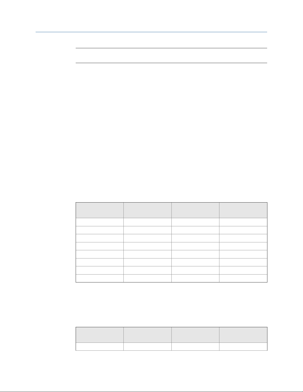
Installation prerequisites
Important
Provide fire prevention measures and equipment per local regulations.
Flanges with 4 and 8 bolts
• First round - 30% of final torque (flange sequential order)
• Second round- 60% of final torque (flange sequential order)
• Third round - 100% of final torque (flange sequential order)
• One final time - clockwise or counter clockwise sequentially around the flange
Flanges with 12 or more bolts
• First round - 20% of final torque (flange sequential order)
• Second round - 40% of final torque (flange sequential order)
• Third round - 80% of final torque (flange sequential order)
• Fourth round - 100% of final torque (sequential order)
• One final time - clockwise or counter clockwise sequentially around the flange
5.3 Torque values (flanges)
Reference torque values for Daniel Control Valve (ft-lb) flange connectionsTable 5-1:
Nominal pipe size
(NPS) ANSI class 150 ANSI class 300 ANSI class 600
2 90 90 90
3 90 160 160
4 90 160 250
6 160 160 400
8 160 250 550
10 250 400 800
12 250 550 800
16 400 800 1400
5.4 Torque pattern sequences
Cross-pattern tightening sequence when using single toolTable 5-2:
Nominal pipe size
(NPS) ANSI class 150 ANSI class 300 ANSI class 600
2 1-3-2-4 1-5-3-7 2-6-4-8 1-5-3-7 2-6-4-8
66 Daniel Models 762, 763, 765, 766 and 767 Control Valves
Page 77

Installation prerequisites
Cross-pattern tightening sequence when using single tool (continued)Table 5-2:
Nominal pipe size
(NPS) ANSI class 150 ANSI class 300 ANSI class 600
3 1-3-2-4 1-5-3-7 2-6-4-8 1-5-3-7 2-6-4-8
4 1-5-3-7 2-6-4-8 1-5-3-7 2-6-4-8 1-5-3-7 2-6-4-8
6 1-5-3-7 2-6-4-8 1-7-4-10 2-8-5-11
3-9-6-12
8 1-5-3-7 2-6-4-8 1-7-4-10 2-8-5-11
3-9-6-12
10 1-7-4-10 2-8-5-11
3-9-6-12
12 1-7-4-10 2-8-5-11
3-9-6-12
16 1-9-5-13 3-11-7-15
2-10-6-14 4-12-8-16
1-9-5-13 3-11-7-15
2-10-6-14 4-12-8-16
1-9-5-13 3-11-7-15
2-10-6-14 4-12-8-16
1-11-6-16 3-13-8-18
5-15-10-20 2-12-7-17
4-14-9-19
1-7-4-10 2-8-5-11
3-9-6-12
1-7-4-10 2-8-5-11
3-9-6-12
1-11-6-16 3-13-8-18
5-15-10-20 2-12-7-17
4-14-9-19
1-11-6-16 3-13-8-18
5-15-10-20 2-12-7-17
4-14-9-19
1-11-6-16 3-13-8-18
5-15-10-20 2-12-7-17
4-14-9-19
The position of the number 1 screw determines the position of the clockwise rotation of
the subsequent screws.
5.5 Tools required for control valve installation
Flange installation tools
Follow all best practice procedures when installing or removing flanges.
Control valve components
The control valve does not have pre-installation requirements. If installation is required for
maintenance purposes, use the following tools:
• Socket wrench
• Adjustable wrench
• T-handle or extended Allen wrench
• Arbor press (may be needed for 4- and 6-inch valves)
• Retaining ring pliers
User manual 67
Page 78

Installation prerequisites
5.6 Typical installation
Although quick opening of the surge relief valve is desirable, if the valve were to shut in a
similar time, then further problems could occur - a valve slamming shut can produce
hydraulic shock (water hammer) in the system, creating an undesirable secondary surge.
Good surge relief system design will include systems to dampen, or slow the valve, on
closing. Often, this requires sophisticated reverse flow when opening and reduced orifice
to limit closing speed. This design is extremely versatile and offers the user the opportunity
to determine different closing speeds as required by the system when the valve is built.
Typical installation - 766 Gas loaded pressure relief valveFigure 5-1:
NOTICE
The Daniel Models do not comply with any internationally over-pressurization protection
recognized codes. What the Daniel Models do is to allow the movement of an undetermined
amount of substance within a pressurized system, not from a pressurized system.
5.7 Nitrogen system
The nitrogen system must supply a constant pressure to the valve, even under conditions
of varying ambient temperatures. Normally, the system will be designed to use standard
gas bottles and will incorporate a control panel to regulate the nitrogen supply pressure.
68 Daniel Models 762, 763, 765, 766 and 767 Control Valves
Page 79

Installation prerequisites
Supply pressure should be set at, or close to, the relief pressure required. The valve is a
hydraulically balanced piston design which means that the forces applied across the piston
are proportional to the pressures. This is particularly important when setting the system
up: the gas pressure set point, minus the force exerted by the spring is the relief pressure
for the system.
The gas tank should be buried underground or insulated to keep the gas at a constant
temperature. Thermal expansion, caused by the increases in temperature of the gas will
change the relief set point.
5.8 Gas plenum tank installation and sizing
The gas plenum should be buried underground to keep the gas at a constant temperature.
Thermal expansion, caused by increases in temperature, will change the relief set point.
The effective volume of the gas plenum decreases as the valve opens by an amount equal
to the piston displacement. The size of the gas plenum determines the percentage that
the pressure relief set point will change as the valve opens. For example, a 12" valve piston
displacement is 554 cubic inches from a closed to an open position. Thus, when fully
opened, an equal amount of gas is contained in a volume that is decreased by 554 cubic
inches. From Boyles Law, we can see the proportional increase in pressure as: P1V1 =P2V2.
For example, a 12" valve piston displacement is 554 cubic inches from a closed to an open
position.
Before the gas tank is sized, determine:
1. Set point (PSI)
2. Valve size
3. Allowable over-pressure (PSI)
P
1
P
2
V1
PD
Exponent
No consideration is given to the volume of gas contained in tubing, fittings and the top
portion of the valve itself.
Valve required set pressure, valve closed
Maximum allowable overpressure, valve open
Total gas volume (gas chamber and volume behind main valve piston)
Volume displacement of main valve piston
0.709 derived from K factor of Nitrogen (1.41)
(1)
(1)
(typically 10%)
Gas plenum sizing formula Equation 5-1:
P
0.709
2
PD
(
)
P
(
1
P
0.709
2
− 1
)
P
1
V =
User manual 69
Page 80

Installation prerequisites
Volume displacement (Main valve piston)
Valve size Cubic inches Valve size Cubic inches
2" 3.7 8" 165
3" 12.6 10" 347
4" 20 12" 554
6" 66 15" 1,207
Example:
(12" valve, set point 640 psi and over-pressure is 40 psi)
Solving V1 Equation 5-2:
V1=
V1=
14, 046.121
231
576.74779
0.041061
= 14, 046.12in
= 60.80U .S .Gallons(TankVolume
3
)
P
1
P
2
V
1
PD
1 U.S. Gallon
Note
Valve is fitted with light piston spring which provides:
• 4 psi Preload with valve close
• 6 psi Preload with valve open
This 4 and 6 psi Preload must be subtracted from P1 & P2, respectively, to arrive at actual gas
pressure.
Conditions assume adiabatic compression.
640 psi set point required, minus 4 psi spring load plus 14.7 psi (adjustment to
absolute) = 650.7 psi
680 psi maximum allowable over-pressure, minus 6 psi spring load 14.7 psi
(adjustment to absolute) = 688.7 psi
Unknown
3
554 in
231 cu. in.
5.9 Nitrogen system panel
A nitrogen control panel may be advantageous if there are large variations in ambient
temperature or if it is not practical to bury the nitrogen plenum underground.
The control panel can be used to provide a precise output which is used to regulate the set
point of the gas loaded relief valve.
70 Daniel Models 762, 763, 765, 766 and 767 Control Valves
Page 81

Installation prerequisites
The Nitrogen Supply Cylinders shown in Figure 5-2 are used as a source of the nitrogen and
the control panel will use this to replenish the nitrogen pressure within the valve anytime it
falls below the desire set point. Conversely if the set point at the valve is higher than the
desired set point, the control panel will relieve the excess pressure from the valve.
Since the Daniel valve does not consume nitrogen, unlike competitive valves, the need to
adjust nitrogen is normally due to changes in pressure due to ambient temperatures.
The nitrogen set point pressure is measured using a pressure transmitter, which can be
transmitted to a remote control room. The system nitrogen set point is field adjustable by
authorized personnel. A complete Emerson control valve system can be furnished that will
include the surge relief valve, inlet/outlet piping, nitrogen control panel, supply cylinders
and the plenum. The system is carefully designed, engineered and assembled onto a
structural skid with a lifting facility (as shown below in Figure 5-2).
Surge relief system with nitrogen panel and plenumFigure 5-2:
User manual 71
Page 82

Installation prerequisites
72 Daniel Models 762, 763, 765, 766 and 767 Control Valves
Page 83

6 Installation procedure
Topics covered in this chapter:
• External components assembly
• Oil filling procedure for valve with drain port
6.1 External components assembly
Install the external components (e.g., flanges) onto the pipeline.
The control valve is assembled at the factory. The components do not need to be
uninstalled or reinstalled unless maintenance is required.
CAUTION!
SURFACE TEMPERATURE HAZARD
Installation procedure
The control valve body and piping may be extremely hot or cold.
Wear personal protective equipment appropriate to the situation when working with the
control valve. Adhere to your company's safety standards and practices.
Failure to comply may cause serious injury.
6.1.1 Fasteners
The property class of the fastener is in accordance with ASME B16.5.
Stud bolt and nut types
All fasteners (nuts and studs) used in assembling Daniel control valves are made of one of
the materials listed in the table below.
Bolt material selectionTable 6-1:
Bolt material selection Description
ASTM SA 193 Grade B7 <63.5 mm (<2.5 in.) High strength low alloy steel
ASTM SA 193 Grade B7M <63.5 mm (<2.5 in.) Controlled strength low alloy steel
ASTM SA 320 Grade L7 <63.5 mm (<2.5 in.) High strength low alloy low temperature steel
ASTM SA 320 Grade L7M <63.5 mm (<2.5 in.) Controlled hardness low temperature steel
ASTM SA 449 <25.4 mm (<1.0 in.) Quenched and tempered steel
ASTM SA 453 Grade 660 High temperature stainless steel
User manual 73
Page 84

Installation procedure
Selection of stud bolts and nuts
• Select all fasteners (nuts and studs) used in a hydrostatic test according to the flange
size and quantity listed in ASME ANSI B16.5.
• Use the shortest stud bolt that permits full engagement of the thread through the
nut by hand-tightening.
• Use only clean, rust-free nuts and stud bolts.
Note
Ensure that once the nut is tightened two threads outside the nut are exposed. The only exception is
when a flange requires hydraulic bolt tensioning. The manufacturer of the hydraulic bolt tensioning
equipment will specify number of exposed threads outside the nut.
• Do not use damaged or worn stud bolts or nuts.
• Do not use nuts or stud bolts that do not fit together correctly.
• Do not use nuts or stud bolts without grade or type identification.
• Do not mix nuts or stud bolts of different coatings. Different nut and stud bolt
coatings require different torques to achieve the same bolt tension.
• Do not assemble nuts with the identification hard stamp against the back face of the
flange
Stud bolt and nut storage
Remove each nut and bolt as a pair. Thread the matching nut back onto the bolt. Stack
them in a fashion that will not cause thread damage.
Reuse of stud bolts and nuts
The reuse of threaded fasteners is permitted on Daniel control valves under the following
conditions:
• Fasteners are clean, free of corrosion, paint, thread damage, cracks, teeth marks
(caused by wrenches) or other signs of damage.
• Fasteners are not tightened to or beyond their yield strength.
• Fasteners have not lost their coating.
Compare the threads of a used stud bolt with the thread of a new stud bolt. Finger-tighten
the nut over the entire thread length of the bolt.
6.2 Oil filling procedure for valve with drain port
The oil reservoir is supplied with two sight gauges. When properly filled and the valve
closed, the oil level will be half way between the two sight gauges. In the closed valve
position oil is visible only at the lower sight gauge. Oil visible in the upper sight gauge
indicates that the valve is in the open position or that the line product is present in the oil
reservoir.
1. a) Locate NPT plug on the Cylinder Head as shown in Figure 6-1.
74 Daniel Models 762, 763, 765, 766 and 767 Control Valves
Page 85

Installation procedure
NPT plug locationFigure 6-1:
2. Remove plug.
Removing NPT plugFigure 6-2:
3. Pour oil through the reservoir port shown in Figure 6-3. The oil should come out of
the bleed port.
User manual 75
Page 86

Installation procedure
Nitrodome oil portFigure 6-3:
4. Add Teflon tape or liquid thread sealant to the plug and close the bleed port. Use the
recommended torque for this NPT connection.
5. Pour the additional of oil into the reservoir port until the level is just below the top
sight gauge.
76 Daniel Models 762, 763, 765, 766 and 767 Control Valves
Page 87

7 Testing the product
7.1 Commission the control valve
After installation, commission the control valve to ensure that the equipment is working
properly.
1. Inspect all bolts used to secure the control valve in-line to ensure that proper
mounting procedures have been followed and that flange connections are leak-free.
2. Evaluate the system setup to ensure that all components are in the correct
operating sequence.
3. Evaluate the system setup to ensure that all components are in the correct sequence
for accurate product measurement. Some components are isolation valves,
strainers, flow straighteners, turbine meters, downstream sections, etc.
WARNING!
ISOLATING UPPER CHAMBER HAZARD
The only function of the socket-head screws that secure the cylinder head to the cylinder
is to provide a mechanical joint between components during assembly or disassembly.
Testing the product
Do not Isolate the upper chamber (Nitrogen Reservoir) during Shell or Hydro Testing,
pressure must be applied to the inlet and upper chamber at the same time.
User manual 77
Page 88

Testing the product
78 Daniel Models 762, 763, 765, 766 and 767 Control Valves
Page 89

Part III
Operate
Operate
User manual 79
Page 90

Operate
80 Daniel Models 762, 763, 765, 766 and 767 Control Valves
Page 91

8 Operation parameters
Topics covered in this chapter:
• Control valve normal operation
• Features and benefits
• Oil reservoir
• Applications
8.1 Control valve normal operation
All series 700 control valves are pressure balanced, single-seated piston operated with 45°
body construction.
Unique design features and unit-built construction ensures positive leak-proof
performance. In addition, the basic valves body and internals are the same throughout the
line, simplifying spare parts inventory and reducing costs.
Operation parameters
8.2 Features and benefits
• Balanced piston principle, spring biased
• Linear valve action: Rectangular ports provide smooth linear action with maximum
flow and minimum pressure drop
• Uniform speed of response: Uniform area above main piston provides uniform
opening and closing.
• Positive (pressure type sealing) O-ring seal and valve seats are not affected by fluid
viscosity or pressure drop
• High capacity 45° (in-line) valve body ensures high capacity at low pressure drop
• Zero leakage: Contoured edge of piston provides a tight seal and ensures drip-tight
operation and dead-end service
• Unit-built construction: All internal parts, including seat ring, can be removed as a
unit without disturbing valve body and connections.
• Simple design: No diaphragms or stuffing boxes
8.3 Oil reservoir
The Oil reservoir is supplied with two (2) sight gauges. In a closed position, the oil is visible
only at the lower sight gauge. Should oil be visible in the upper sight gauge, this indicates
line product is leaking into the reservoir or that the valve is open. If no oil is visible in the
lower sight gauge, this indicates the reservoir oil is leaking into the product stream.
User manual 81
Page 92
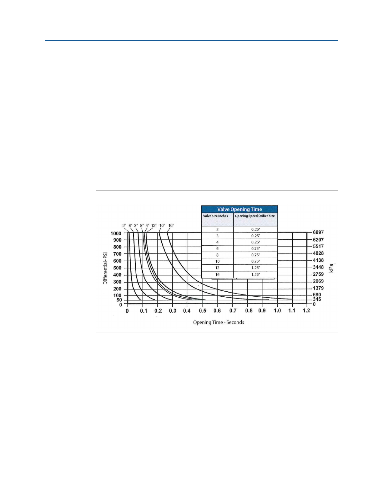
Operation parameters
Oil specifications
Use a light weight non-detergent oil between 5-30 Centipoise based on climate conditions
of user.
The oil to fill the reservoir, gas tank, pressure switch and other interconnecting pieces is to
be supplied by the customer.
Opening/Closing speed
The opening speed of the valve is virtually unrestricted. Closing speed is standard at three
(3) seconds from a full open position, based on gas pressure being 25 psi (1,724 kPa)
above line pressure. The fastest closure is limited to 0.5 seconds at 1,500 seat ring. For
closure speeds longer than three (3) seconds, the orifice size can be changed to match
customer requirements. It should be noted that the calculated closing speeds are a
function of the viscosity of the oil in the reservoir. Typical valve opening times are
illustrated in Figure 8-1 .
Typical valve opening timeFigure 8-1:
Pressure switch
The valve will open any time gas pressure is less than line pressure. A pressure switch is
recommended in the gas supply line to the valve for alarm actuation should gas pressure
decrease below an acceptable operating level.
82 Daniel Models 762, 763, 765, 766 and 767 Control Valves
Page 93

8.4 Applications
NOTICE
The Daniel Models do not comply with any internationally over-pressurization protection
recognized codes. What the Daniel Models do is to allow the movement of an undetermined
amount of substance within a pressurized system, not from a pressurized system.
Back pressure control
The Model 762 is ideally suited for back pressure control and minimum pressure drop.
When line pressure exceeds the gas pressure, the valve will open and follow the Cv curve
for pressure loss.
Typical applications for minimum back pressure control requirements are illustrated in
Figure 8-2.
• Reference API Chapter 5 for minimum back pressure requirements of the turbine
and ultrasonic meters.
• On the end of a pipeline or any point along the pipeline where the upstream
pressure is subject to drop below minimum requirements.
• Discharge of centrifugal pumps to maintain maximum efficiency and to start against
a closed valve.
Operation parameters
Back pressure controlFigure 8-2:
Pipeline pump station by-pass
Most pipeline have booster pumps at intervals along the pipeline. If a pump station is shutdown, it must be by-passed or the entire pipeline is subject to being shutdown. The Model
766 control valve, when installed as shown in Figure 8-3, will automatically open and bypass the pump station when line pressure exceeds set point.
User manual 83
Page 94
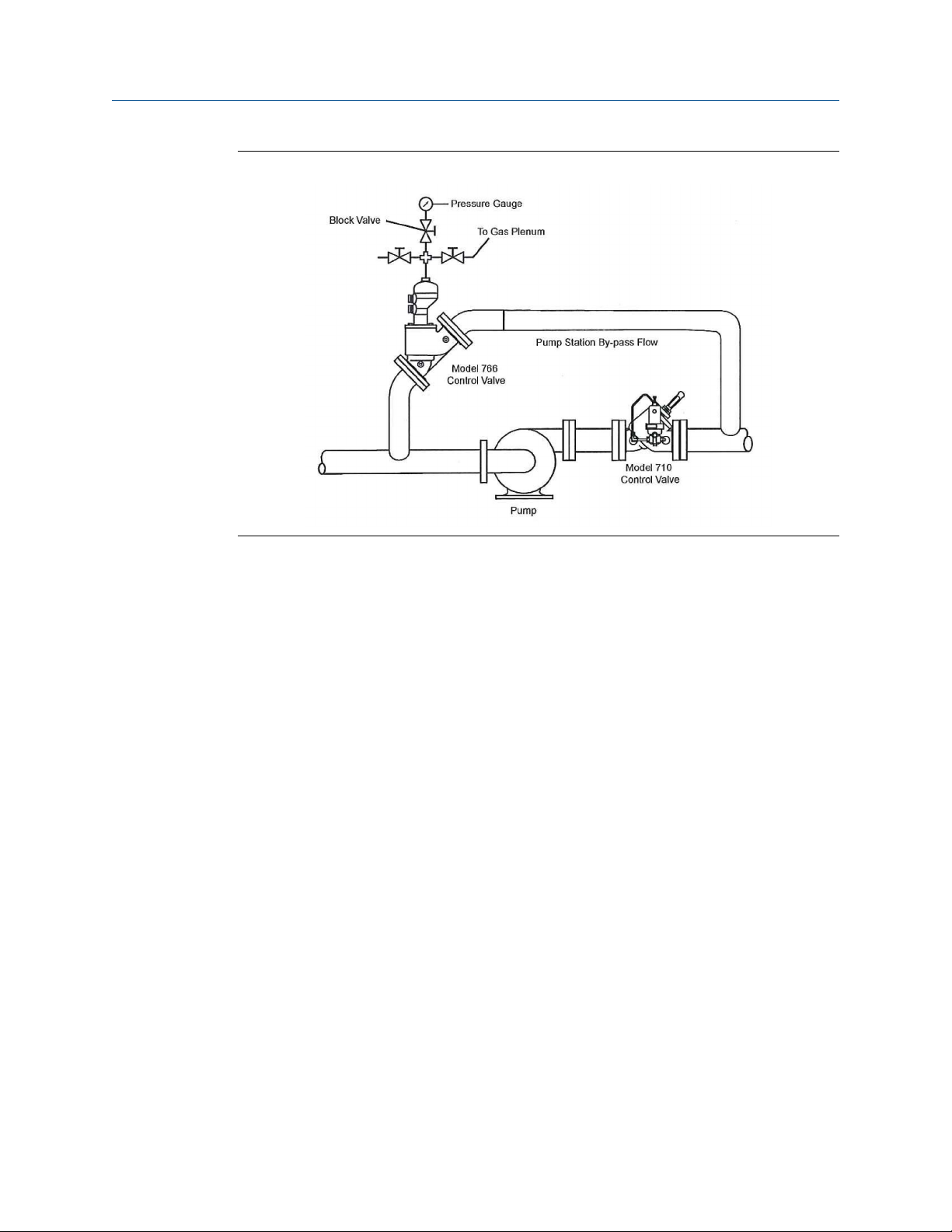
Operation parameters
Pipeline pump station by-passFigure 8-3:
84 Daniel Models 762, 763, 765, 766 and 767 Control Valves
Page 95

Part IV
Maintain
Chapters covered in this part:
• Planned maintenance
• Corrective maintenance
• Spare parts
• Decommission
Maintain
User manual 85
Page 96

Maintain
86 Daniel Models 762, 763, 765, 766 and 767 Control Valves
Page 97

9 Planned maintenance
Topics covered in this chapter:
• Maintenance considerations
• Tools required for mechanical components
• Mechanical disassembly
• Mechanical assembly
• Planned maintenance tasks
9.1 Maintenance considerations
Read and understand all instructions and operating procedures before performing
maintenance procedure, internal component inspection, or field requirement changes.
To ensure safe and accurate performance, only informed and trained personnel should
install, operate, repair and maintain this product.
Planned maintenance
Follow the recommendations below before servicing the control valve:
1. Label all parts or place parts in labeled containers during disassembly.
2. Do not use metal clamping devices in direct contact with any control valve part or
surface.
Important
All control valve adjustments were completed at the factory during liquid calibration and should not
require field setup.
9.2 Tools required for mechanical components
Flange installation tools
Follow all best practice procedures when installing or removing flanges.
Control valve components
The control valve does not have pre-installation requirements. If installation is required for
maintenance purposes, use the following tools:
• Socket wrench
• Adjustable wrench
• T-handle or extended Allen wrench
• Arbor press (may be needed for 4- and 6-inch valves)
• Retaining ring pliers
User manual 87
Page 98

Planned maintenance
9.3 Mechanical disassembly
To ensure safe and accurate performance, only informed and trained personnel should
install, operate, repair and maintain this product.
WARNING!
PRESSURE HAZARD
The control valve is subject to pressurized fluids. Isolate the control valve upstream and
downstream.
Always depressurize the control valve before disassembly.
Failure to comply may cause high pressure fluids to leak, resulting in death or serious injury.
9.3.1 Cylinder disassembly (NPS 2-12)
1. Remove the nuts that secure the cylinder head to the valve body.
2. Alternately tighten the jack-out screws until the cylinder assembly is free to be lifted
out of the valve body.
3. Lift the cylinder assembly by the cylinder head. Remove it from the valve body and
set it in a vertical position with the cylinder head on top.
4. Before removing the screws, place the cylinder assembly in an arbor press to
immobilize the cylinder head. This is to prevent sudden spring pressure from being
released and causing injury or damage.
CAUTION!
SPRING PRESSURE HAZARD
Follow the instructions in step 5.
Failure to comply may cause release of spring pressure, resulting in serious injury or
equipment damage.
5. Use an Allen wrench to remove the screws that secure the cylinder head to the
cylinder, and then gradually release the arbor press to remove the cylinder head
from the cylinder. Remove the indicator guard and the upper bearing first, if your
valve has a position indicator.
6. Remove the valve spring, indicator stem, retaining ring, washer, and piston from the
cylinder. Remove only the valve spring and the piston if your valve does not have a
position indicator.
7. Turn the cylinder over with the ports on top when removing the high pressure seat
ring. Remove the set screw from the seat ring. Turn the seat ring counterclockwise
to remove the seat ring and then remove the O-ring from the cylinder.
88 Daniel Models 762, 763, 765, 766 and 767 Control Valves
Page 99

9.3.2 Cylinder disassembly NPS 16 valve only
Important
The 16" valve does NOT disassemble as a complete assembly. The first step is to remove the cylinder
head from the valve body.
Prerequisites
The construction of the NPS 16 valve cylinder assembly is different from all other valve
cylinder assemblies and requires different procedures. The following tools are needed to
disassemble and reassemble the control valve.
• Socket wrench
• Adjustable wrench
• Extended allen wrench set
• Mallet and cold chisel
• Appropriate lifting gear and sling
• (2) all thread rods, 3/4" no. 10x18"-24" long
• (2) 3/4" no. 10x2" bolts with 3/4" flatwashers
• Hand pump
• Drip pan
• (3) hoist rings 1"-8" nnc 10,000 lb, part number 1-504-90-094
Planned maintenance
Procedure
1. Completely block all product flow to the valve and drain the process line.
2. Disconnect "Y" port on top of cylinder head and relieve pressure in the valve.
WARNING!
SPRING FORCE HAZARD
Use extreme caution when removing the cylinder head from the valve body.
Failure to disassemble or reassemble the valve without carefully being aware of the
force of the spring against the cylinder head may result in death, serious injury or
damage to the equipment.
WARNING!
SPRING TENSION HAZARD
Do not remove jack screws (long bolts). Jack screws are spring tension retaining devices
and must NOT be tampered with. Follow disassembly procedure above.
Failure to comply with instructions may result in serious personal injury or damage to
the equipment.
User manual 89
Page 100

Planned maintenance
Figure 9-1:
Models 762, 763, 765, 766 and 767 Control Valve jack screws and
spring
3. Product remains in the valve below the cylinder head in the piston. Place a drip pan
below the valve before starting step 4 (removal of the cylinder head).
4. Remove nuts; except the jack screws (long bolts).
5. Alternatively, loosen the remaining two nuts from threaded rods allowing the
cylinder head to slowly raise from the valve body and relieve spring tension. Oil from
the piston will flow into drip pan. It is important to avoid damaging or bending the
threaded rods during this operation.
6. Once spring tension is fully relieved, remove remaining nuts from threaded rods and
lift cylinder head and reservoir away from threaded rods.
7. Remove spring from valve.
8. Use a hand pump to remove the remaining oil from the cylinder/piston assembly.
9. Insert (2) 3/4" - 10 N.C. bolts with large washers behind bolt heads into threaded
holes in the cylinder.
10. Use a chain or other suitable lifting device attached to the bolts and carefully
remove the cylinder and piston from the valve body.
11. Secure the cylinder assembly and remove the piston from the cylinder by pushing
the bottom of the piston.
12. Remove (24) bolts (item 12) while holding the seal ring to the cylinder. Remove the
seal ring and the seat O-ring.
13. Inspect all components, remove any foreign material and replace O-rings, as
necessary.
90 Daniel Models 762, 763, 765, 766 and 767 Control Valves
 Loading...