

Page 1

Maintenance and Troubleshooting Manual
Par t Number 3-9000-764 Rev ision F
DanielTM 3814 Liquid Ultrasonic Flow Meter
December 2017
Page 2

Page 3

Flow Lifecycle Services for Daniel products
Location Tel ephone number Fax number
North America/Latin America +1.713.467.6000 +1.713.827.4805
Daniel Customer Service +1.713.827.6314 +1.713.827.6312
USA (toll free) +1.888.356.9001 +1.713.827.3380
Asia Pacific (Republic of Singapore) +65.6777.8211 +65.6777.0947.0743
Europe (Stirling Scotland, UK) +44 (0)1786.433400 +44 (0)1786.433401
Middle East Africa (Dubai, UAE) +971 4 8118100 +971 4 8865465
Daniel Measurement and Control, Inc. (Headquarters)
11100 Brittmoore Park Drive
Houston, TX 77041 USA
http://www.Emerson.com
Email
• Customer Service: Daniel.SystemSales@Emerson.com
• Customer Support: Daniel.SystemSales@Emerson.com
• Asia-Pacific: danielap.support@emerson.com
• Europe: danielEMA.cst@emerson.com
Return Material Authorization (RMA)
A Return Material Authorization (RMA) number must be obtained prior to returning any equipment for any reason. Download the
RMA form from the Support Services web page by selecting the link below.
http://www.daniel/rma
Page 4

Signal words and symbols
This is a safety alert symbol. It is used to alert you to potential physical injury hazards. Obey
all safety messages that follow this symbol to avoid possible injury or death.
Safety alert symbol
Danger indicates a hazardous situation which, if not avoided, will result in death or serious
injury.
Warning indicates a hazardous situation which, if not avoided, could result in death or serious
injury.
Caution indicates a hazardous situation which, if not avoided, could result in minor or
moderate injury.
Caution indicates a hazardous situation which, if not avoided, could result in minor or
moderate injury.
Pay special attention to the following signal words, safety alert symbols and statements:
Tip: Tip provides information or suggestions for improved efficiency or best results.
Note: Note is “general by-the-way” content not essential to the main flow of information.
Page 5

Important safety instructions
Installing, operating or maintaining a Daniel product improperly could lead to serious injury or
death from explosion or exposure to dangerous substances. To reduce this risk:
• Comply with all information on the product, in this manual, and in any local and national
codes that apply to the product.
• Do not allow untrained personnel to work with this product.
• Use Daniel parts and work procedures specified in this manual.
Daniel Measurement and Control, Inc. (Daniel) designs, manufactures and tests products to
function within specific conditions. Because these products are sophisticated technical
instruments, it is important that the owner and operation personnel strictly adhere both to the
information printed on the product and to all instructions provided in this manual prior to
installation, operation, and maintenance.
Daniel also urges you to integrate this manual into your training and safety program.
BE SURE ALL PERSONNEL READ AND FOLLOW THE INSTRUCTIONS IN THIS MANUAL AND ALL
NOTICES AND PRODUCT WARNINGS.
Product owners (Purchasers):
• Use the correct product for the environment and pressures present. See technical data
or product specifications for limitations. If you are unsure, discuss your needs with your
Daniel representative.
• Inform and train all personnel in the proper installation, operation, and maintenance of
this product.
• To ensure safe and proper performance, only informed and trained personnel shou
install, operate, repair and maintain this product.
• Verify that this is the correct instruction manual for your Daniel product. If this is not
the correct documentation, contact Daniel at 1-713-827-6314. You may also download
the correct manual from
• Save this instruction manual for future reference.
• If you resell or transfer this product, it is your responsibility to forward this instruction
manual along with the product to the new owner or transferee.
• ALWAYS READ AND FOLLOW THE INSTALLATION, OPERATIONS, MAINTENANCE AN
TROUBLESHOOTING MANUALS AND ALL PRODUCT WARNINGS AND INSTRUCTIONS.
• Do not use this equipment for any purpose other than its intended service. This ma
result in property damage and/or serious personal injury or death.
:
http://www.daniel.com
ld
D
y
Page 6

Product Operation Personnel:
• To prevent personal injury, personnel must follow all instructions of this manual prior to
and during operation of the product.
• Follow all warnings, cautions, and notices marked on, and supplied with, this product.
• Verify that this is the correct instruction manual for your Daniel product. If this is not
the correct documentation, contact Daniel at 1-713-827-6314. You may also download
the correct manual from
• Read and understand all instructions and operating procedures for this product.
• If you do not understand an instruction, or do not feel comfortable followin
instructions, contact your Daniel representative for clarification or assistance.
• Install this product as specified in the INSTALLATION section of this manual per
applicable local and national codes.
• Follow all instructions during the installation, operation, and maintenance of this
product.
• Connect the product to the appropriate pressure and electrical sources when and
where applicable.
• Ensure that all connections to pressure and electrical sources are secure prior to and
during equipment operation.
• Use only replacement parts specified by Daniel. Unauthorized parts and procedures can
affect this product's performance, safety, and invalidate the warranty. "Look-a-like"
substitutions may result in deadly fire, explosion, release of toxic substances
improper operation.
• Save this instruction manual for future reference.
:
ht
tp://www.daniel.com
g the
or
Page 7

Notice
THE CONTENTS OF THIS PUBLICATION ARE PRESENTED FOR INFORMATIONAL PURPOSES ONLY,
AND WHILE EVERY EFFORT HAS BEEN MADE TO ENSURE THEIR ACCURACY, THEY ARE NOT TO
BE CONSTRUED AS WARRANTIES OR GUARANTEES, EXPRESSED OR IMPLIED, REGARDING THE
PRODUCTS OR SERVICES DESCRIBED HEREIN OR THEIR USE OR APPLICABILITY. ALL SALES ARE
GOVERNED BY DANIEL'S TERMS AND CONDITIONS, WHICH ARE AVAILABLE UPON REQUEST. WE
RESERVE THE RIGHT TO MODIFY OR IMPROVE THE DESIGNS OR SPECIFICATIONS OF SUCH
PRODUCTS AT ANY TIME.
DANIEL DOES NOT ASSUME RESPONSIBILITY FOR THE SELECTION, USE OR MAINTENANCE OF
ANY PRODUCT. RESPONSIBILITY FOR PROPER SELECTION, USE AND MAINTENANCE OF ANY
DANIEL PRODUCT REMAINS SOLELY WITH THE PURCHASER AND END-USER.
TO THE BEST OF DANIEL'S KNOWLEDGE THE INFORMATION HEREIN IS COMPLETE AND
ACCURATE. DANIEL MAKES NO WARRANTIES, EXPRESSED OR IMPLIED, INCLUDING THE IMPLIED
WARRANTIES OF MERCHANTABILITY AND FITNESS FOR A PARTICULAR PURPOSE WITH RESPECT
TO THIS MANUAL AND, IN NO EVENT, SHALL DANIEL BE LIABLE FOR ANY INCIDENTAL, PUNITIVE,
SPECIAL OR CONSEQUENTIAL DAMAGES INCLUDING, BUT NOT LIMITED TO, LOSS OF
PRODUCTION, LOSS OF PROFITS, LOSS OF REVENUE OR USE AND COSTS INCURRED INCLUDING
WITHOUT LIMITATION FOR CAPITAL, FUEL AND POWER, AND CLAIMS OF THIRD PARTIES.
PRODUCT NAMES USED HEREIN ARE FOR MANUFACTURER OR SUPPLIER IDENTIFICATION ONLY
AND MAY BE TRADEMARKS/REGISTERED TRADEMARKS OF THESE COMPANIES.
DANIEL AND THE DANIEL LOGO ARE REGISTERED TRADEMARKS OF DANIEL INDUSTRIES, INC.
THE EMERSON LOGO IS A TRADEMARK AND SERVICE MARK OF EMERSON ELECTRIC CO.
Page 8

Warranty and Limitations
1. LIMITED WARRANTY: Subject to the limitations contained in Section 2 herein, Daniel Measurement &
Control, Inc. ("Daniel") warrants that the licensed firmware embodied in the Goods will execute the
programming instructions provided by Daniel, and that the Goods manufactured by Daniel will be free from
defects in materials or workmanship under normal use and care and Services will be performed by trained
personnel using proper equipment and instrumentation for the particular Service provided. The foregoing
warranties will apply until the expiration of the applicable warranty period. Goods are warranted for twelve
(12) months from the date of initial installation or eighteen (18) months from the date of shipment by Daniel,
whichever period expires first. Consumables and Services are warranted for a period of 90 days from the date
of shipment or completion of the Services. Products purchased by Daniel from a third party for resale to Buyer
("Resale Products") shall carry only the warranty extended by the original manufacturer. Buyer agrees that
Daniel has no liability for Resale Products beyond making a reasonable commercial effort to arrange for
procurement and shipping of the Resale Products. If Buyer discovers any warranty defects and notifies Daniel
thereof in writing during the applicable warranty period, Daniel shall, at its option, correct any errors that are
found by Daniel in the firmware or Services or repair or replace F.O.B. point of manufacture that portion of the
Goods or firmware found by Daniel to be defective, or refund the purchase price of the defective portion of the
Goods/Services. All replacements or repairs necessitated by inadequate maintenance, normal wear and usage,
unsuitable power sources or environmental conditions, accident, misuse, improper installation, modification,
repair, use of unauthorized replacement parts, storage or handling, or any other cause not the fault of Daniel
are not covered by this limited warranty, and shall be at Buyer's expense. Daniel shall not be obligated to pay
any costs or charges incurred by Buyer or any other party except as may be agreed upon in writing in advance
by Daniel. All costs of dismantling, reinstallation and freight and the time and expenses of Daniel's personnel
and representatives for site travel and diagnosis under this warranty clause shall be borne by Buyer unless
accepted in writing by Daniel. Goods repaired and parts replaced by Daniel during the warranty period shall be
in warranty for the remainder of the original warranty period or ninety (90) days, whichever is longer. This
limited warranty is the only warranty made by Daniel and can be amended only in a writing signed by Daniel.
THE WARRANTIES AND REMEDIES SET FORTH ABOVE ARE EXCLUSIVE. THERE ARE NO REPRESENTATIONS OR
WARRANTIES OF ANY KIND, EXPRESS OR IMPLIED, AS TO MERCHANTABILITY, FITNESS FOR PARTICULAR
PURPOSE OR ANY OTHER MATTER WITH RESPECT TO ANY OF THE GOODS OR SERVICES. Buyer acknowledges
and agrees that corrosion or erosion of materials is not covered by this warranty.
2. LIMITATION OF REMEDY AND LIABILITY
PERFORMANCE. THE REMEDIES OF BUYER SET FORTH IN THIS AGREEMENT ARE EXCLUSIVE. IN NO EVENT,
REGARDLESS OF THE FORM OF THE CLAIM OR CAUSE OF ACTION (WHETHER BASED IN CONTRACT,
INFRINGEMENT, NEGLIGENCE, STRICT LIABILITY, OTHER TORT OR OTHERWISE), SHALL DANIEL'S LIABILITY TO
BUYER AND/OR ITS CUSTOMERS EXCEED THE PRICE TO BUYER OF THE SPECIFIC GOODS MANUFACTURED OR
SERVICES PROVIDED BY DANIEL GIVING RISE TO THE CLAIM OR CAUSE OF ACTION. BUYER AGREES THAT IN NO
EVENT SHALL DANIEL'S LIABILITY TO BUYER AND/OR ITS CUSTOMERS EXTEND TO INCLUDE INCIDENTAL,
CONSEQUENTIAL OR PUNITIVE DAMAGES. THE TERM "CONSEQUENTIAL DAMAGES" SHALL INCLUDE, BUT NOT
BE LIMITED TO, LOSS OF ANTICIPATED PROFITS, REVENUE OR USE AND COSTS INCURRED INCLUDING
WITHOUT LIMITATION FOR CAPITAL, FUEL AND POWER, AND CLAIMS OF BUYER'S CUSTOMERS.
: DANIEL SHALL NOT BE LIABLE FOR DAMAGES CAUSED BY DELAY IN
Page 9

Maintenance and Troubleshooting Manual Table of Contents
3-9000-764 Rev F December 2017
Contents
Preface
Section 1: Routine maintenance
1.1 Meter maintenance ......................................................................................... 1
1.2 Field hydrostatic pressure testing procedures ................................................... 3
1.3 Routine Maintenance ...................................................................................... 4
1.3.1 Maintenance logs and reports .............................................................................. 4
1.3.2 Pipeline cleaning maintenance ............................................................................ 7
1.3.3 High Viscosity piping requirements...................................................................... 8
Section 2: Troubleshooting
2.1 Meter status alarms ........................................................................................ 9
2.1.1 Check status....................................................................................................... 10
2.1.2 System alarm ..................................................................................................... 10
2.1.3 Chord A, Chord B, Chord C and Chord D alarm.................................................... 11
2.1.4 Field I/O alarm.................................................................................................... 11
2.1.5 Validity alarm ..................................................................................................... 11
2.1.6 Comms alarm..................................................................................................... 11
2.1.7 Communications................................................................................................ 11
2.2 Troubleshooting the meter ............................................................................ 12
2.2.1 Meter maintenance............................................................................................ 19
2.2.2 Unable to connect direct serial or external serial modem ................................... 28
2.2.3 Unable to connect to meter ............................................................................... 28
2.2.4 Ethernet connections ......................................................................................... 28
2.2.5 Direct serial connections .................................................................................... 28
2.3 Troubleshoot Maintenance log files and trend files .......................................... 29
2.3.1 Files Do Not Appear in Workbook....................................................................... 29
2.3.2 Microsoft® Excel® Log/Export Options are not Available ................................... 29
2.3.3 Maintenance Logs or Trend files are not created................................................. 30
2.3.4 Windows® XP with Security Update................................................................... 33
Section 3: Meter maintenance
3.1 Meter maintenance ....................................................................................... 35
3.2 Transducer field removal and installation ........................................................ 38
3.2.1 Transducer removal and installation................................................................... 40
Table of Contents i
Page 10

Table of Contents Maintenance and Troubleshooting Manual
December 2017 3-9000-764 Rev F
3.3 Transducer housing removal and installation ...................................................43
3.3.1 Manually modifying the Calibration Parameters .................................................48
3.4 Transducer cable removal and installation ....................................................... 52
3.5 Replace the meter electronics ........................................................................60
3.5.1 Replace CPU Module or optional I/O Module.......................................................61
3.5.2 Fuse Replacement ..............................................................................................63
3.5.3 Replace Backplane, I.S. Barrier or Power Supply board ........................................64
3.5.4 Acquisition Module replacement ........................................................................70
Appendix A: Conversion factors
A.1 Conversion factors per units of measurement..........................................................75
A.2 K Factor conversions ................................................................................................76
K-Factor and inverse K-Factor 76
Appendix B: Engineering Drawings
B.1 Daniel 3410 Series Ultrasonic Flow Meter Drawings.................................................77
Appendix C: Index
C.1 Manual Index ...........................................................................................................79
ii Table of Contents
Page 11

Maintenance and Troubleshooting Manual List of Tables
3-9000-764 Rev F December 2017
List of Tables
Table 2-1 Troubleshooting .............................................................................................................. 12
Table 2-2 Maintenance.................................................................................................................... 20
Table A-1 Conversion factors per units of measurement .................................................................. 75
List of Tables iii
Page 12

List of Tables Maintenance and Troubleshooting Manual
December 2017 3-9000-764 Rev F
iv List of Tables
Page 13

Maintenance and Troubleshooting Manual List of Figures
3-9000-764 Rev F December 2017
List of Figures
Figure 1-2 Flange stabilizers .......................................................................................................... 2
Figure 1-3 Maintenance log collection parameters ........................................................................ 4
Figure 1-4 Trend log collection ...................................................................................................... 5
Figure 1-5 Archive log collection parameters................................................................................. 6
Figure 1-6 High Viscosity meter tube and Venturi piping requirements......................................... 8
Figure 2-1 Meter Monitor status alarms......................................................................................... 9
Figure 2-2 Status summary............................................................................................................ 9
Figure 2-3 Status Summary ......................................................................................................... 10
Figure 2-4 Meter Monitor (Summary) view ................................................................................. 19
Figure 2-5 Meter Monitor (Detailed) view ................................................................................... 19
Figure 2-6 Excel® 2000 Tools Menu ............................................................................................ 30
Figure 2-7 Excel® Trusted Access Setting.................................................................................... 31
Figure 2-8 Excel® 2007 Tools Menu ............................................................................................ 31
Figure 2-9 Excel® 2007 Developer tab - Macro Security .............................................................. 32
Figure 3-2 Flange stabilizers ........................................................................................................ 36
Figure 3-3 Transducer (LT-01/LT-04/LT-08) ................................................................................. 38
Figure 3-4 Transducer (LT-03/LT-05/LT-09) ................................................................................. 38
Figure 3-5 Transducer assembly ................................................................................................. 39
Figure 3-6 Tools required............................................................................................................. 40
Figure 3-7 Transducer security seal removal ............................................................................... 41
Figure 3-8 Transducer installation ............................................................................................... 42
Figure 3-9 Transducer housing ................................................................................................... 43
Figure 3-10 Transducer disassembly ............................................................................................. 44
Figure 3-11 Transducer installation ............................................................................................... 47
Figure 3-12 Transducer Swap Out Wizard ..................................................................................... 48
Figure 3-13 Transducer Swap Out Wizard - Select Components Page ........................................... 49
Figure 3-14 Transducer Swap Out Wizard - Select Components Page ........................................... 50
Figure 3-15 Flow meter transducer cables and ports ..................................................................... 52
Figure 3-16 Transducer security seal removal ............................................................................... 53
Figure 3-17 Flow meter transducer tie wraps ................................................................................ 54
Figure 3-18 Flow meter Acquisition Module wiring........................................................................ 56
Figure 3-19 Transmitter Electronics Enclosure security seals ......................................................... 58
Figure 3-20 Base Enclosure security seals....................................................................................... 59
List of Figures v
Page 14

List of Figures Maintenance and Troubleshooting Manual
December 2017 3-9000-764 Rev F
Figure 3-21 Transmitter electronics ..............................................................................................60
Figure 3-22 CPU or I/O Module replacement..................................................................................61
Figure 3-23 Transmitter electronics enclosure security seals .........................................................62
Figure 3-24 Fuse holder cap ...........................................................................................................63
Figure 3-25 Backplane board replacement ...................................................................................64
Figure 3-26 I.S. Barrier board replacement ...................................................................................66
Figure 3-27 Transmitter electronics enclosure security seals .........................................................67
Figure 3-28 Power Supply board replacement ..............................................................................68
Figure 3-29 Conduit removal .........................................................................................................70
Figure 3-30 Transmitter Electronics Enclosure and Base Enclosure security seal removal ...............71
Figure 3-31 Transmitter Electronics Enclosure removal .................................................................71
Figure 3-32 Acquisition Module cable and transducer wiring ........................................................72
vi List of Figures
Page 15
Maintenance and Troubleshooting Manual Section 1: Routine maintenance
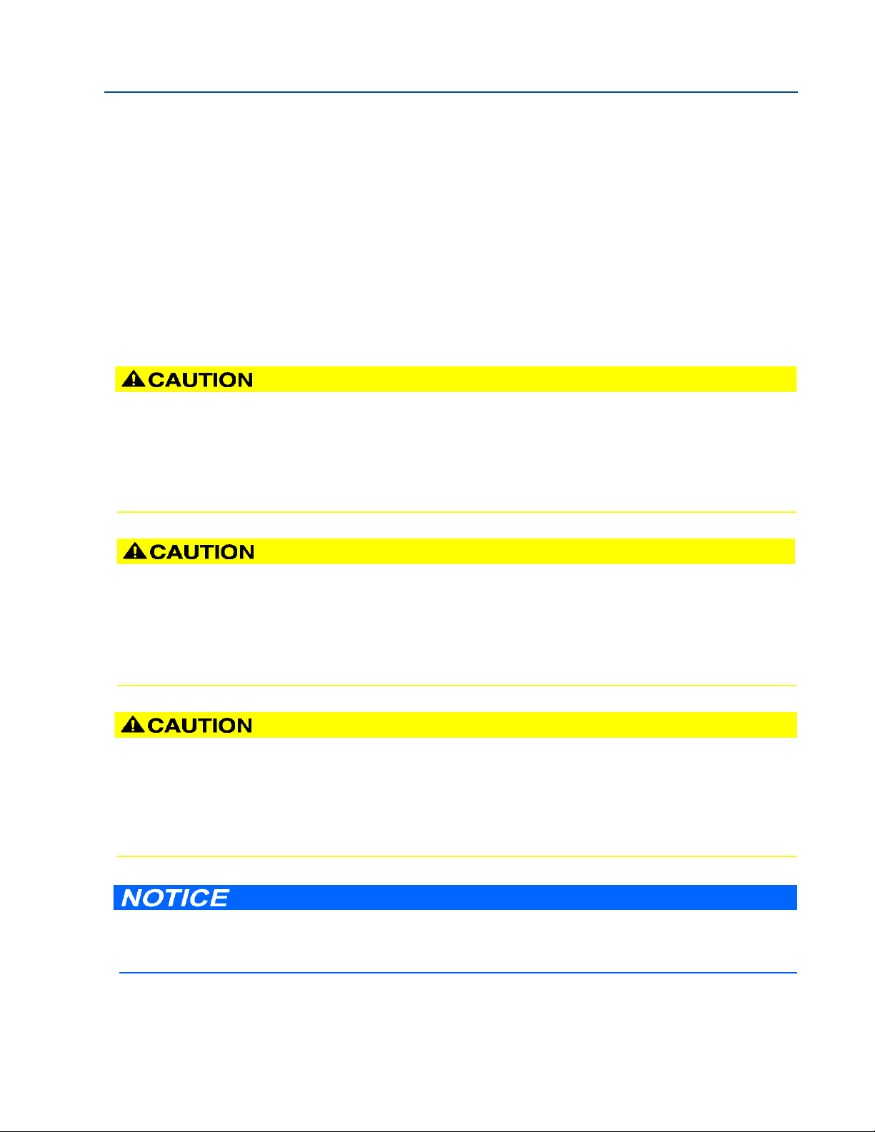
SURFACE TEMPERATURE HAZARD
The meter body and piping may be extremely hot or cold
Wear appropriate personal protective equipment when coming in contact with the meter. Failure to do so may
result in injury.
TRANSPORTATION HAZARD
When moving the meter, do not insert the forks of a forklift into the bore.
inserting the forks may cause the meter to become unstable, resulting in injury or damage to the bore and
sealing face.
TRIPPING HAZARD
Clear all obstacles or obstructions from the work area when transporting, installing or removing the
meter.
Failure to clear the work area may cause injury to personnel.
Prior to lifting the unit, refer to the flow meter nameplate or outline dimensional (general arrangement)
drawing for the assembled weight.
3-9000-764 Rev F December 2017
11
Section 1: Routine maintenance
1.1 Meter maintenance
This section includes discussion of the maintenance of Daniel 3814 Liquid Ultrasonic Flow
Meters.
For reference, you may download the Daniel MeterLink Quick Start Manual from:
http://www2.emersonprocess.com/en-US/brands/daniel/Flow/ultrasonics/Pages/Ultrasonic.aspx
Meter maintenance 1
Page 16
Section 1: Routine maintenance Maintenance and Troubleshooting Manual
Figure 1-2 Flange stabilizers
CRUSHING HAZARD
Do not remove flange stabilizers
Attempting to do so may allow the meter to roll, resulting in serious injury or equipment damage.
A.
A. Flange stabilizers
ESCAPING FLUIDS HAZARD
The purchaser of the meter is responsible for the selection of Daniel components/seals and materials
compatible with the chemical properties of the measurement fluid.
Failure to select suitable meter components/seals may cause escaping fluids, resulting in injury or equipment
damage.
December 2017 3-9000-764 Rev F
2 Meter maintenance
Page 17

Maintenance and Troubleshooting Manual Section 1: Routine maintenance
LEAKAGE OR PRESSURE CONTAINING PARTS FAILURE
Use precautions to eliminate hazards to personnel in the event of leakage or failure of
the liquid ultrasonic meter pressure containing parts or failure of the test equipment
and to prevent over-pressurization during the test procedure.
Failure to do so may result in injury to personnel or cause damage to the equipment.
3-9000-764 Rev F December 2017
1.2 Field hydrostatic pressure testing procedures
The Daniel 3814 Liquid Ultrasonic Flow Meter can be hydro-tested without any special
preparations. The transducers are not exposed to the process pressure and can remain installed
in the meter.
The liquid ultrasonic meter pressure containing parts include but are not limited to the
transducer housings. These pressure containing parts are pressure tested while attached to the
meter body as a completed ultrasonic meter assembly. The hydrostatic test is verification of the
pressure containing capability of the liquid ultrasonic meter pressure containing parts and the
seals that seal them.
Field hydrostatic pressure testing procedures 3
Page 18

Section 1: Routine maintenance Maintenance and Troubleshooting Manual
December 2017 3-9000-764 Rev F
1.3 Routine Maintenance
Routine maintenance operations requires adherence to all applicable regulations and laws and
safety training for personnel to perform the maintenance operations. Review your
organization’s best practices procedures before performing routine maintenance.
1.3.1 Maintenance logs and reports
To monitor the performance health of the meter, and ensure it is operating within acceptable
specifications, routine diagnostics should be performed. Collecting a maintenance log gives
you a snapshot of the current health of the meter and you can compare the inspection reports
from previously saved logs. Use the Logs/Reports menu and click Maintenance Logs and
Reports. Daniel MeterLink displays the Maintenance Logs and Reports dialog. Choose the time
duration, log format and collection rate for the output file and click the Start button. You can
open the file immediately after it is generated or view it at a later time. It is recommended that a
Maintenance log be collected after an upset in the system.
In establishing a baseline to be used for the trending of the meter diagnostics, it is very helpful if
a set of log files are collected immediately after the meter has been installed in the field.
Preferably, collect the log files at several velocities within the operating range of the meter. This
helps establish that the flow profile is relatively constant throughout the meters operating
range (except velocities below 3 ft/sec where the profile may vary).
Maintenance log collection
Figure 1-3 Maintenance log collection parameters
4 Routine Maintenance
Page 19

Maintenance and Troubleshooting Manual Section 1: Routine maintenance
3-9000-764 Rev F December 2017
Trend maintenance log collection
Merging the results of two or more Maintenance logs into a single file, allows you to build a
historical database of the meter’s performance. Trending the logs indicates changes from the
original installation of the meter over time. Looking at a single inspection report, that is either
collected monthly or quarterly, will only give you an indication of the meter's current health.
Figure 1-4 Trend log collection
This is important since many diagnostics change slowly over time. Trending the maintenance
logs helps identify these changes and makes problems much more obvious than merely viewing
a single inspection report. The Trending feature is integral to Daniel MeterLink which allows all
important parameters to be trended. Daniel MeterLink supports trending files in a Microsoft®
Excel® workbook from multiple 3814 meter maintenance logs. Some parameters like gain,
signal level, and noise level level may show a shift over time which can be useful in detecting
changes in the meter and the installation.
Maintenance logs to be trended must all have matching column headings. This means the logs
must be in the same units (i.e. U.S. Customary or Metric), must have the same pressure type (i.e.
gage or absolute), and must have the same time base (1/second, 1/minute, 1/hour, 1/day). If
not, an error message will be displayed stating the column headings do not match and the file
will not be added to the Workbook to trend list.
Maintenance logs and reports 5
Page 20

Section 1: Routine maintenance Maintenance and Troubleshooting Manual
December 2017 3-9000-764 Rev F
Archive log collection
Archive logs may be collected and the options include:
• Daily log - generated every 24 hours on the Contract Hour.
• Hourly log - generated every hour at the top of the hour.
• Event log - collects the alarm and event log records.
Figure 1-5 Archive log collection parameters
The logs may be collected in a single file or you can choose to collect one type of log. Each of the
Meter Archive logs include the Meter Configuration file.
6 Maintenance logs and reports
Page 21
Maintenance and Troubleshooting Manual Section 1: Routine maintenance
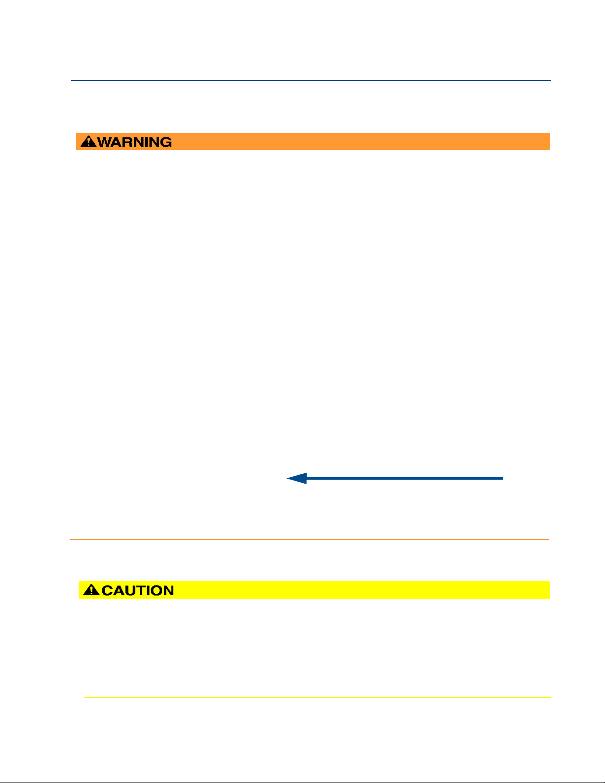
BURST HAZARD
Before pipeline cleaning and maintenance (“pigging operations”), remove straightening vanes or flow
conditioners. Failure to do so may cause excessive pressure in the meter system, resulting in serious injury/death
or equipment damage.
3814 Liquid Ultrasonic Flow Meter with flow conditioner for uni-directional flow
3814 Liquid Ultrasonic Flow Meter with flow conditioner for bi-directional flow
Flow conditioner
Straightening device
Flow conditioner
Straightening device
Flow conditioner
Straightening device
3-9000-764 Rev F December 2017
1.3.2 Pipeline cleaning maintenance
Straightening vanes or flow profilers must be removed during pipeline cleaning maintenance
operations (“pigging operation”). if the meter run is pigged with a flow conditioner in line,
pressure may build up and cause the pipes and flanges to burst and severely injure personnel.
The excessive pressure may damage the meter or the transducer ports may collect debris which
may impede data acquisition and flow measurement.
Pipeline cleaning maintenance 7
Page 22
Section 1: Routine maintenance Maintenance and Troubleshooting Manual
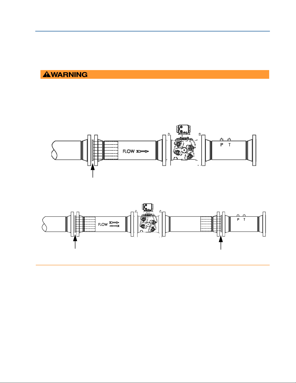
HIGH VISCOSITY FLOW MEASUREMENT METER RECALIBRATION
In high viscosity meter applications, if the connection between the upstream meter flange
(Figure 1-6, Item D) and the Venturi reducer (Figure 1-6, Item C) is disassembled or disturbed for
any reason, the meter will need to be recalibrated in accordance with Daniel recommendations. Alignment of this flange joint is critical in the performance of the meter. It is
recommended to consult Daniel Support for assistance when re-aligning this joint.
Failure to recalibrate the meter and correctly reinstall the flanged joint will result in faulty flow measurement.
A.
B.
C.
E.
F.
G.
B. Flow conditioner and flange gaskets
C. Venturi conical reducer
D. Upstream meter flange
E. 3814 Liquid Ultrasonic Flow Meter
F. Pressure tap
D.
A. Meter tube
G. Temperature tap
December 2017 3-9000-764 Rev F
1.3.3 High Viscosity piping requirements
The piping requirements for High Viscosity meter applications are shown in Figure 1-6.
Figure 1-6 High Viscosity meter tube and Venturi piping requirements
8 High Viscosity piping requirements
Page 23
Maintenance and Troubleshooting Manual Section 2: Troubleshooting
3-9000-764 Rev F December 2017
APPENDIX A:DANIEL METERLINK
Section 2: Troubleshooting
2.1 Meter status alarms
Run Daniel MeterLink and open the Meter Monitor (Summary) view to perform a diagnostics
health check.
Figure 2-1 Meter Monitor status alarms
If the meter is measuring flow and operating within the established parameters the Meter Status
LED is green. If the Meter Status LED is red, an active alarm exists that requires you to take
corrective action. Click the Check Status button to display the Status Summary screen. The
alarms are shown with the primary causes listed first. Click the question mark next to the
alarm to display a help topic related to the alarm and recommended actions to resolve the issue.
Figure 2-2 Status summary
Section 2: Troubleshooting 9
Page 24
Section 2: Troubleshooting Maintenance and Troubleshooting Manual
A.
B.
A. Active alarm conditions from Meter Monitor page
B. Status summary page with alarm examples
December 2017 3-9000-764 Rev F
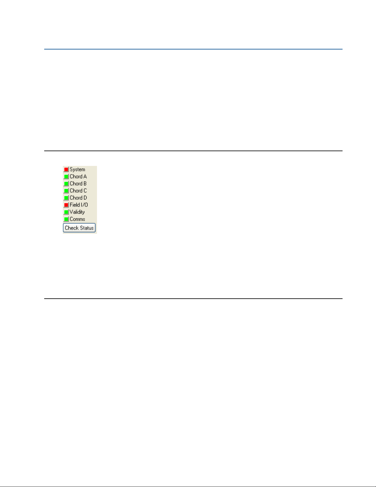
2.1.1 Check status
Click the Check Status button if any of the LEDs are yellow or red to see more specific
information causing the status alarm. Some alarms do not require an acknowledge and will clear
automatically when the alarm condition goes away. Alarms that require a user to acknowledge
them will have a button to the right titled
Wait and sends a request to the meter to clear the alarm. The alarm will disappear from the
to
Check Status dialog once the alarm actually clears.
ACK. Clicking the AC K button changes the button text
Click the
description of all alarms present.
Figure 2-3 Status Summary
Following is a list and a brief description of the types of alarms:
Check Status button and DUI opens the Status Summary dialog box that gives a short
• System
• Power Loss
• Field I/O
• Validity
• Comms
• Check Status
2.1.2 System alarm
The System alarm indicates a failure in the hardware that should be addressed by a service
technician. This includes memory checksum errors and communication errors within the
hardware. A Red LED indicates a System alarm condition. Collect a Maintenance log and an
audit/alarm log and then, contact your Daniel service representative.
10 Check status
Page 25
Maintenance and Troubleshooting Manual Section 2: Troubleshooting
3-9000-764 Rev F December 2017
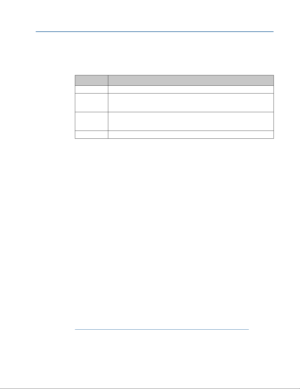
2.1.3 Chord A, Chord B, Chord C and Chord D alarm
Chord A, Chord B, Chord C, and Chord D - These alarms indicate how a chord is functioning.
LED Color Problem
Green No alarms are present. Chord is operating properly.
Yellow At least one sample in the batch caused an alarm but it did not cause the chord to fail.
The sample will not be used in the batch. Discarding occasional samples can occur
during normal operation such as during flow velocity changes.
Red The chord has failed or is in acquisition. This chord is not used for this batch. Chords
that have failed or are shown to be in acquisition for repeated batches indicates that the
meter should be inspected by a service technician.
Gray The chord has manually been set to inactive.
2.1.4 Field I/O alarm
Reports various field I/O devices that are in alarm. Click the Check Status button for more details
on specific alarms. The field is grayed out if the Daniel 3810 Series Ultrasonic Flow Meter does
not support this alarm.
2.1.5 Validity alarm
This alarm indicates that the meter may not be measuring accurately. Click Check Status to see a
description of which validity alarms are active. The validity alarms
issue with the meter collecting enough information from the chords to make an accurate
measurement. The validity alarms for pressure and temperature indicate that the value is above
or below the alarm limits for these values. Red and green are the only colors used for this alarm.
2.1.6 Comms alarm
The Comms alarm indicates that communications between DUI and the meter failed. This could
be due to a poor communication link. DUI continues to retry communications. Red and green
are the only colors used for this alarm.
2.1.7 Communications
The Communications Analyzer (via Daniel MeterLink Tools> Menu>Communications Analyzer
menu path) displays communications between Daniel MeterLink and the ultrasonic meter. This
utility is useful for troubleshooting communications to the meter. It displays many of the TCP/IP
commands between Daniel MeterLink and the connected meter.
For troubleshooting communications with the 475 Field Communicator for the HART®
Protocol, refer to Section 5 of the Emerson 475 Field Communicator User’s Manual, Rev D. This
manual may be downloaded from the following location:
QMeter and QFlow indicate an
http://www2.emersonprocess.com/en-US/brands/Field-Communicator/Pages/Support.aspx
For troubleshooting communications with AMS Device Manager, refer to the help
documentation and support at the following web site:
http://www2.emersonprocess.com/en-US/brands/amssuite/amsdevicemanager/Pages/AMSDeviceManager.aspx
Chord A, Chord B, Chord C and Chord D alarm 11
Page 26
Section 2: Troubleshooting Maintenance and Troubleshooting Manual
December 2017 3-9000-764 Rev F
2.2 Troubleshooting the meter
Table 2-1 and the following sections show errors that may occur with the meter hardware,
firmware or connections and recommended actions to resolve the problem(s).
Table 2-1 Troubleshooting
Error Recommended action(s)
Acquisition Module Error
Acquisition Module is not compatible with firmware
Chord failure
CPU Module LINK LED
• Check interconnect cable between Acquisition Module and the CPU Module.
• Attempt the Program Download procedure to install the firmware.
— Cycle power to the meter.
— Replace the Acquisition Module.
— If the Acquisition Module cannot be reprogrammed, collect a complete
Archive log and contact your local area Daniel service representative.
• Upgrade the firmware in the meter to the latest version using Daniel MeterLink
(Too ls| Pro gram Downloa d). Contact your Daniel service representative to obtain
the latest firmware or download the firmware from:
http://www2.emersonprocess.com/en-US/brands/daniel/Pages/Daniel.aspx
• Replace the Acquisition Module.
• Chord is hard failed (Chord A, Chord B, Chord C or Chord D) and meter is unable to
obtain measurement data from this pair of transducers.
— If Chord A is failed and no other transducers are failed or are reporting status
alerts, the issue is most likely isolated to this pair of transducers or its cabling.
Check the transducer wiring for this pair of transducers to make sure connections are secure and wired correctly.
— Verify that the meter run is not partially full where the top transducer pair are
not submerged in the process fluid.
— Verify the average gain of this transducer pair is not above 90dB. The gain
value can be read in Daniel MeterLink on the Monitor page.
— Remove the transducer cable from the transducer and measure the resistance
with an Ohm meter across the two pins on the back of the transducer
housing. If the value is over 2 ohms, replace the transducers.
— If transducer cabling allows, swap cabling of failed transducer pair with a pair
with equal path lengths. If the alarm remains active for this chord, then the
transducers are working properly. If this alarm clears but the chord that was
swapped now fails, the issue is with the transducer.
— Collect a Maintenance Log, Configuration file and Waveform stream file with
Daniel MeterLink and contact your Daniel service representative.
• When connecting directly:
— Check the cross-over cable connection (P/N 1-360-01-596)
• When Using a Hub:
— Use straight-through patch cable between the meter and the hub and a
straight-through patch cable between the hub and the PC
— Do not connect either the meter or PC to the hub UPLINK port.
— Check the CPU Module LED 1 is on (either solid red or flashing green). If the
LED is not on, check power to the meter.
— If the LED is on, check the Ethernet cable connections
12 Troubleshooting the meter
Page 27

Maintenance and Troubleshooting Manual Section 2: Troubleshooting
3-9000-764 Rev F December 2017
Table 2-1 Troubleshooting
Error Recommended action(s)
CPU Module LINK LED is on but I
can't communicate with the meter
using Ethernet
Communication line connected to
the flow computer but no signal is
received
If you are connecting for the first time,
• Enable the DHCP switch on the CPU Module
• Verify that the PC has received an IP address from the meter as follows:
— bring up Command prompt window (Start->Run->(type)cmd)
— in the Command prompt window, type ipconfig
• If you get the following: IP 192.168.135.35 (note: the last .35 can be up to .44) with
a Subnet Mask of 255.255.255.0 and Default Gateway you should be able to
connect to the meter
• If you get the following:
— Ethernet adapter Local Area Connection 1:
— IP Address: 0.0.0.0
— the PC has not yet received an IP address from the DHCP server wait (up to 30
seconds) to receive an IP address before attempting to connect to the meter
— after 30 seconds the PC has not received an IP address from the DHCP server
or the IP address shown above (from ipconfig) is different from the range of
192.168.135.35 through 192.168.135.44, verify that the PC is configured to
receive its IP address automatically (via DHCP)
• Check for loose connections at the flow meter and the flow computer.
• Check the CPU Module settings.
Troubleshooting the meter 13
Page 28

Section 2: Troubleshooting Maintenance and Troubleshooting Manual
December 2017 3-9000-764 Rev F
Table 2-1 Troubleshooting
Error Recommended action(s)
Communication issues due to
blocked network ports
Communicating with meter but all
chords display failures
Cannot communicate with Daniel
MeterLink program
• Blocked network ports on the computer running Daniel MeterLink or on a company
LAN can prevent connections to the meter or prevent certain features from
working. These issues may occur over Ethernet, Modem and Direct serial connections. Reference the list of network ports used by Daniel MeterLink in the Help file
and the symptoms of having blocked ports. Contact your IT department for
assistance in resolving these issues.
• Error condition of a blocked network:
— Cannot connect to a meter
— Cannot collect Archive log files
— Cannot view or stream waveforms in Waveform Viewer or Signal Analyzer.
— Cannot upgrade firmware.
— Communications lost over serial or modem connections while
Daniel MeterLink is idle on a screen.
• Symptoms of blocked network:
— If a PING is blocked on this network port, serial or modem connections could
be lost after approximately 15 seconds of inactivity. This issue can be
confirmed by checking the log_meter log file in the Temp data folder. The
path of the Temp data folder is shown in the Daniel MeterLink About dialog.
— A blocked FTP port will generally not prevent a connection to the meter, but
will prevent log collections and program downloads. A blocked FTP port could
prevent a connection in the event the meter is running a newer version of
firmware for which Daniel MeterLink does not currently have a database configuration file. If this is a case, a message stating “Error reading database
config file dbconfig<databaseversion>.xml from the meter.” will be displayed.
— A blocked DB API port will report “Error 10001 opening database connection
to <IP address>”.
— A blocked Streaming port will report an error message “Unable to open a
control socket”. This will occur when opening the Signal Analyzer window or
clicking Read or Stream to File in the Waveform Viewer.
• Verify that the resistance of transducers is within Specification (2 Ω).
• Check the Acquisition Board.
• Check the interconnect cables between the Base assembly and the Transmitter
Electronics Enclosure.
• Ensure that the meter is properly powered.
• Ensure that the computer cable is properly connected and check your interface pins
(RS-485 or RS-232).
• Verify that the communication parameters of the Daniel MeterLink
correctly set.
program are
• Check RS-485 or RS-232 communication.
14 Troubleshooting the meter
Page 29
Maintenance and Troubleshooting Manual Section 2: Troubleshooting
3-9000-764 Rev F December 2017
Table 2-1 Troubleshooting
Error Recommended action(s)
Cannot communicate with 475 Field
Communicator
Cannot communicate with AMS
Device Manager
Connect to multiple meters via
Ethernet when they are on the same
LAN
Connect to multiple meters via
Ethernet when they are on the same
hub but not connected to an
intranet LAN
Configuration changed
Configuration lost
Electronics Temperature is Out Of
Nominal Range
• Refer to the Emerson 475 Field Communication User’s Manual, Rev F. This manual may
be downloaded from the following location:
http://www2.emersonprocess.com/en-US/brands/Field-Communicator/Pages/
Documentation.aspx
— Note: The 375 Field Communicator is no longer available for purchase since the
release of the 475 Field Communicator. Customer support for the 375 Field
Communicator remains available
• Refer to the AMS help documentation and support at the following web site:
http://www.emersonprocess.com/ams/suppinde.htm
• Configure each meter with a unique user-specified IP address following the initial
communication quick start instructions.
• Contact your IT department for valid IP addresses for your LAN and Gateway
addresses.
• Disable the DHCP server.
• Configure each meter with a unique user-specified IP address
following the initial communication quick start instructions.
• Assign each meter on the hub a unique IP address within the range
192.168.135.150 through 192.168.135.254 (Gateway address for each meter may
be left unconfigured as 0.0.0.0).
• A PC may receive its IP address from an external DHCP server; in this case, one and
only one meter must have its DHCP ser ver enabl ed (the DHCP ser ver will ser ve up to
10 IP addresses to PCs attempting to talk to all meters on the hub).
• Once a meter's IP address is configured, the meter may be connected to the hub
and accessed using that IP address.
• One or more parameters have been modified in the meter's configuration
— Collect an Audit log using Daniel MeterLink in order to see what configuration
parameters changed and when they changed.
— Save the configuration file.
• The meter configuration has reset to default values and the meter is not configured
correctly to measure flow and the meter has performed a Cold Start.
— Unless the Cold Start occurred after upgrading firmware, replace the CPU
board.
— If the cold start occurred after a firmware upgrade, fully re-configure the
meter from a previously saved configuration using the
Edit/Compare Configuration in Daniel MeterLink.
• Temperature of the electronics is out of nominal operating range (below -40 °C or
above 100 °C) which could lead to a system failure.
— Attempt to warm or cool the meter electronics housing.
— If the electronics is mounted to the meter and the process fluid in the meter is
over 65 °C, you must remote mount the electronics off of the meter body.
— Collect a Maintenance log using Daniel MeterLink while the meter is experi-
encing the issue and contact your Daniel service representative.
Troubleshooting the meter 15
Page 30

Section 2: Troubleshooting Maintenance and Troubleshooting Manual
December 2017 3-9000-764 Rev F
Table 2-1 Troubleshooting
Error Recommended action(s)
Flow pressure is outside the alarm
limits
Flow temperature is outside the
alarm limits
• Startup Issues:
— Verify that there is voltage to the pressure sensor from either the meter's
power supply board or from an external power supply.
— If using an analog pressure device, verify that the pressure sensor is properly
wired to the connector.
— Verify the input is properly configured for your pressure input.
— If using a flow computer to write pressure to the meter, verify that it is
properly writing to fixed flow pressure in the proper units.
• Run Time Issues:
— Adjust pressure of process fluid to within alarm limits.
— If using an analog pressure device and input reading is 0, check if IsAI1Avail is
equal to 1 in the Meter Information dialog in Daniel MeterLink. If it is not 1,
either the I/O Board has been removed or is damaged. Reinstall or replace the
board if this value is 0.
— If using an analog pressure device, verify that the pressure sensor is working
properly.
— If using an analog pressure device, recheck wiring and switch settings.
— If a flow computer is writing values to the fixed flow pressure, verify that the
flow computer is still writing valid values without Modbus write errors.
— Reverify the pressure input settings are correct.
• Startup Issues:
— Verify that there is voltage to the temperature sensor from either the meter's
power supply board or from an external power supply.
— If using an analog temperature device, verify that the temperature sensor is
properly wired to the connector.
— Verify the input is properly configured for your temperature input.
— If using a flow computer to write temperature to the meter, verify that it is
properly writing to fixed flow temperature in the proper units.
• Run Time Issues:
— Adjust temperature of process fluid to within alarm limits.
— If using an analog temperature device and input reading is 0, check if
IsAI2Avail is equal to 1 in the Meter Information dialog in Daniel MeterLink. If
it is not 1, either the I/O Board has been removed or is damaged. Reinstall or
replace the board if this value is 0.
— If using an analog temperature device, verify that the temperature sensor is
working properly.
— If using an analog temperature device, recheck wiring and switch settings.
— If a flow computer is writing values to the fixed flow temperature, verify that
the flow computer is still writing valid values without Modbus write errors.
— Reverify the temperature input settings are correct.
16 Troubleshooting the meter
Page 31

Maintenance and Troubleshooting Manual Section 2: Troubleshooting
3-9000-764 Rev F December 2017
Table 2-1 Troubleshooting
Error Recommended action(s)
Program download failed during
firmware upgrade
No power to the unit
• If the meter power fails during a firmware upgrade process, perform a backup
upgrade in an attempt to connect to the meter and download the program again.
— In Daniel MeterLink go to the File pull-down menu and select Program
Settings.
— Enable the Allow FTP-only connection
— For Serial Port Connections: for Daniel 3810 Series Liquid Ultrasonic meters
connect to Port A. You may need to adjust your Meter Directory settings for
the connection so that they match the port default settings. Port A will default
to 19200 baud with a Modbus address of 32.
— For Ethernet Connections: If you are connecting to the meter over an Ethernet
port, you should be able to connect with the same IP address as normal. If this
is unsuccessful, the meter may have defaulted to 192.168.135.100 with a
subnet of 255.255.255.0. Make sure your PC has a compatible address and
attempt a connection using this IP address.
— Make sure your cabling and your Meter Directory record are setup, then
attempt to connect to the meter.
— You will receive a message “Error 10001 opening database connection to...”.
Click OK and you will be prompted to “Attempt FTP-only connection ….”. Click
Yes and if successful, the Daniel MeterLink™ caption displays “…Connected to
<meter name>…”. Go to the To ol s pull down menu and select Program
Download to attempt the firmware upgrade again.
— If the firmware upgrade is successful, the meter should start working as
normally as the meter’s configuration is not normally lost.
— If the configuration is lost, use Daniel MeterLink
to write the saved configuration back to the meter. The saved configuration
files are typically stored in C:\Ultrasonic Data folder.
Edit/Compare Configuration
— Restart the meter to install the firmware. Daniel MeterLink prompts you with a
message that it must disconnect from the meter. Once the firmware upgrade
is complete you will be able to reconnect to the meter with Daniel MeterLink.
— When the meter restarts, it takes about two minutes before you will be able to
reconnect depending on the firmware upgrade being performed. If the
database does need to be reinitialized, it could take up to five minutes.
— After an upgrade, it is recommended to reconnect to the meter and repeat
the Program Download process.
— If all the program components are successfully updated, they will show to be
the same date and version as the Currently Installed Versions and the
Download button will be disabled.
— If one or more components are still not updated, click Download to continue
the upgrade process.
• Check for correct voltage (24 VDC) (refer to the System Wiring Diagram).
• Check the main power source for blown fuse or tripped circuit breaker. Reference
your “as built” installation drawings for your location.
Troubleshooting the meter 17
Page 32

Section 2: Troubleshooting Maintenance and Troubleshooting Manual
December 2017 3-9000-764 Rev F
Table 2-1 Troubleshooting
Error Recommended action(s)
One or more of the chords is not
indicating a reading (reporting
zeros)
Power Failure
Sound velocity is outside defined
limits
Waveform contains an excessive
amount of noise
• Check for loose connections at the cable connectors.
• Check the resistance of the transducers (should be approximately 2 Ω).
• Problem also may be caused by a bad Acquisition Board or interconnect cable.
• Check system status in the Daniel MeterLink program for any flagged errors.
• Check the CPU Module.
• Check the resistance of the failed transducer.
• If Chord A is not indicating, change the transducer cables from Chord B to chord A.
If Chord B then fails, the transducers are bad on Chord A.
• Meter has had power removed for a period of time or the meter restarted itself such
as after a firmware upgrade. The Audit log in the meter indicates the power fail
time.
— If this was an unexpected restart of the meter, verify the integrity of the power
to the meter and make sure that the voltage level is in the range of 11-36 VDC
at the meter.
— If this was a known power fail or restart of the meter, just acknowledge this
alarm.
• The meter's measured average sound velocity is outside the defined limits.
— Verify that all chords are measuring the same Speed of Sound within about
0.15%. Look for alarms that indicate transducer problems and resolve any of
these issues. This could include failing transducers, debris buildup on transducers, or incorrectly entered path lengths in the configuration.
— If the chords agree, adjust the SSMin or SSMax using the Edit/Compare
Config utility in Daniel MeterLink
within these limits.
so the meter's average speed of sound falls
— Collect a Maintenance log using Daniel MeterLink and contact your Daniel
service representative.
• Use the Daniel MeterLink Meter>Signal Analyzer to increase the StackSize until
noise level decreases (settings can be 1 (none) 2, 4, 8, or 16). If increasing the
StackSize is not successful, try turning on the filter or consult with Daniel Customer
Service if you are unsure of how stacking a signal can affect the meter's operation.
18 Troubleshooting the meter
Page 33

Maintenance and Troubleshooting Manual Section 2: Troubleshooting
3-9000-764 Rev F December 2017
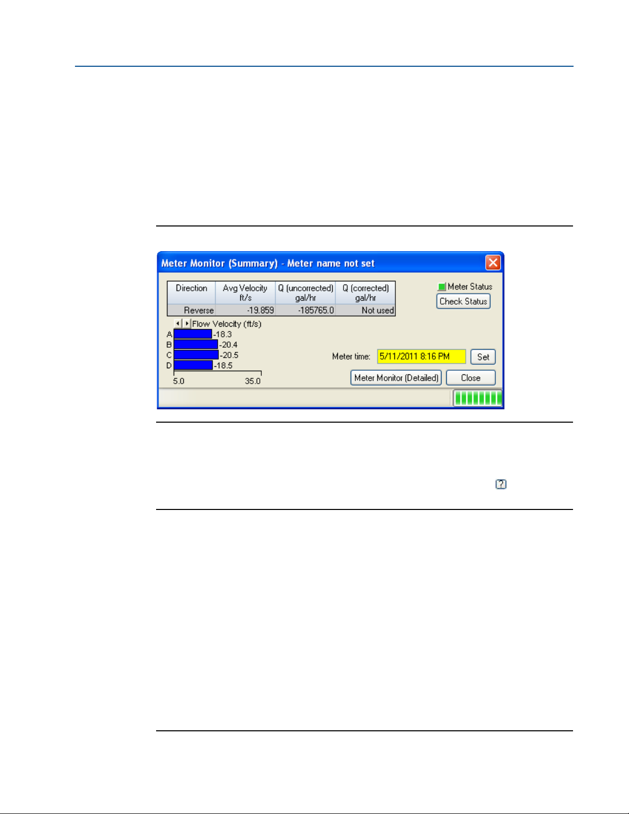
2.2.1 Meter maintenance
The Monitor (Summary) includes the direction of flow measurement, velocity rate, units of
measurement, uncorrected or corrected flow (if applicable for your meter) and a bar graph for a
visual comparison between the velocities for each chord.
Figure 2-4 Meter Monitor (Summary) view
Run Daniel MeterLink and open the Meter Monitor (Detailed) view to perform a diagnostics
health check and or adjust parameters for your site requirements. If you wish to use the Monitor
(Detailed) dialog as the default view, click the checkbox in the lower portion of the dialog box
Figure 2-5 Meter Monitor (Detailed) view
Meter maintenance 19
Page 34

Section 2: Troubleshooting Maintenance and Troubleshooting Manual
December 2017 3-9000-764 Rev F
The following details the information displayed in this dialog box.
• Flow Properties Table - the table at the top of the Meter Monitor dialog box shows basic
information about the condition of the flow in the meter.
• Flow Velocity/Flow Ratios Bar Graph - provides a visual comparison between the
velocities for each chord.
• Chord Speeds of Sound Bar Graph - a visual comparison between the speeds of sound
for each chord.
• Gain/Performance Bar Graph - provides either a visual comparison of the average
upstream and downstream gains for each chord or a visual comparison of the average
upstream and downstream performance for each chord.
• Signal to Noise Bar Graph - provides a visual comparison between the signal to noise
ratio for each chord direction.
• Meter Status Alarms - provides a visual indication of the meter’s status.
• Run time - displays how long the monitor screen has been collecting data.
• Meter Time - the time displayed is the time from the Ultrasonic meter.
(NOTE: If the time displayed has a yellow background, that is an indication that the
meter’s time is more than 10 minutes apart from the PC’s time.)
• Meter Data List - displays read-only data selected from the drop-down list
• Chart - the chart utility displays the data collected for the value selected from the Chart
drop-down list.
Refer to
Table 2 -1 for error resolutions and Tab le 2- 2 for meter maintenance hardware diagnostics.
Table 2-2 Maintenance
Daniel MeterLink utility Diagnostics Action(s)
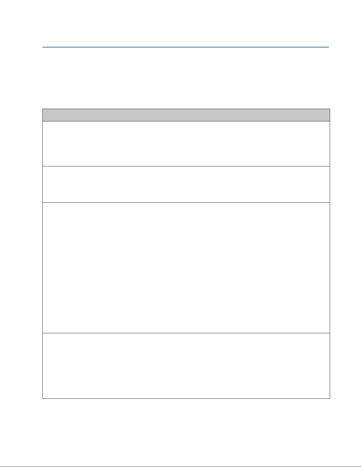
Meter Monitor (Summary) view
• Check Status for active alarms • Meter Status LED is green if there are
no active alarms. This indicates the
meter is measuring flow and
operating within the calibrated
parameters.
• Meter Status LED is red. This indicates
an active alarm. Resolve and acknowledge active alarms as displayed on
the Status Summary page. Click the
Help button beside the alarm
description to display information
about the alarm and recommended
actions to resolve the issue.
20 Meter maintenance
Page 35

Maintenance and Troubleshooting Manual Section 2: Troubleshooting
3-9000-764 Rev F December 2017
Table 2-2 Maintenance
Daniel MeterLink utility Diagnostics Action(s)
Meter Monitor (Detailed) view
• Flow Profile • Flow profile ratios can be viewed by
clicking on the arrows in the upper
left of the chart.
• The flow profile ratios for chords A
and D and chords B and C should be
equal lengths.
• The flow velocity ratio between
chords A & D or chords B & C should
not differ by more than 10%, changes
will be reflected by the symmetr y and
flow profile values.
• If the difference persists, the flow
conditioner (if installed) should be
checked for blockages and if required
the upstream piping should be
cleaned.
• Per path Speed of Sound (SOS) differ-
ences should not be more than .35%,
these can be viewed by clicking on the
arrows in the upper left of the chart.
Negative values are shown in blue.
• The SOS difference can be caused by
buildup on the transducer, incorrect
geometrical and delay time values
and stratification at lower velocities.
• Gains and Signal to Noise Ratios (SNR)
are displayed in decibels and should
be compared to the initial values in
the maintenance logs taken during
the calibration or initial start-up.
• The average chord signal amplitudes
should be compared to the initial
values in the maintenance logs.
• The Check Status chord LED will turn
from green to red if a path is hard
failed. The issue or issues causing the
failure must be corrected before the
alarm can be cleared.
Meter maintenance 21
Page 36

Section 2: Troubleshooting Maintenance and Troubleshooting Manual
December 2017 3-9000-764 Rev F
Table 2-2 Maintenance
Daniel MeterLink utility Diagnostics Action(s)
Meter Monitor (Summary) view
Meter Flow Properties Table
Meter Monitor (Detailed) view
Monitor Chart Selection list
• Flow velocity • Check the flow direction. If reverse
flow is detected, check for valve leaks.
• If the meter run typically has reverse
flow when flow is stopped, reconfigure the ReverseFlowVolLmt to allow a
higher volume from the Field Setup
Wizard> General Page.
• Speed of Sound • Compare Speed of Sound deviation
from measured SOS relative to the
average SOS.
• Check the chord’s SOS.
• Check and correct geometry configu-
ration (pipe diameter, distance
between the transducers (LA), and
delay time).
• If present, resolve transducer issues
(failed transducer, cabling or debris
buildup on the transducer face, or
path length configured incorrectly).
• If SOS is out of range and all checks
were positive, adjust SSMin or SSMax
(consult with a Daniel Service representative before making these adjustments).
22 Meter maintenance
Page 37

Maintenance and Troubleshooting Manual Section 2: Troubleshooting
3-9000-764 Rev F December 2017
Table 2-2 Maintenance
Daniel MeterLink utility Diagnostics Action(s)
Meter Monitor (Detailed) view
Meter Data List
Meter Monitor (Detailed) view
Meter Data List
• Electronics Temperature out of
range
• Temperature of the electronics is out
of nominal operating range
below -40 °C or above 100 °C (-40 °F
or above 212 °F).
— Heat or cool the meter electron-
ics housing. If operating
temperature exceeds 65
remote mount the Transmitter
Electronics Enclosure.
o
C,
• Electronics voltage out of range • Systems voltages are valid if 1.0V,
1.2V, 2.5V, 3.3V or the Acquisition
Module valid voltages are 1.2V, 2.5V
or 3.3V.
• Replace the CPU Module if one or
more of the System Voltages is out of
range.
• Replace the Acquisition Module if one
or more of the voltages is out of
range.
MeterLink Tools Menu‘
• Frequency output • Run the Frequency Outputs test
• If the output reads zero, you may
require a pull up resistor 1.2kOHM,
0.5W.
Meter maintenance 23
Page 38

Section 2: Troubleshooting Maintenance and Troubleshooting Manual
December 2017 3-9000-764 Rev F
Table 2-2 Maintenance
Daniel MeterLink utility Diagnostics Action(s)
MeterLink Tools Menu
MeterLink Tools Menu
• Analog outputs • Run Analog Outputs test and verify
outputs are within 4mA -20mA range
— 0% = 4mA
— 25% = 8mA
— 50% = 12mA
— 75% = 16mA
— 100% = 20 mA
• Digital outputs • Run the Digital Outputs test.
• Digital Output Content is in relation
to frequency validity and flow
direction configuration and polarity.
24 Meter maintenance
Page 39

Maintenance and Troubleshooting Manual Section 2: Troubleshooting
3-9000-764 Rev F December 2017
Meter Hardware Diagnostics Action(s)
Meter Electronics
MeterLink Logs/
Reports Menu
• Acquisition Module communications error • Check firmware revision and upgrade if
necessary using Daniel MeterLink Tools>Program Download.
• If the CPU Module LED 5 is not flashing green,
check interconnect cable between acquisition
Module and the CPU Module.
• If the CPU Board LED 5 is not flashing green,
replace Acquisition Module.
• Meter performed a Warm Start or a Warm
start required
• Meter performed a Warm Start:
— Collect an Archive event log (Audit log)
using Daniel MeterLink to view configuration parameters changes and when
they changed.
• Warm start required:
— When you make changes to the trans-
ducer characteristics, sample rates, the
device number, or a Modbus map file.
Meter maintenance 25
Page 40

Section 2: Troubleshooting Maintenance and Troubleshooting Manual
December 2017 3-9000-764 Rev F
Meter Hardware Diagnostics Action(s)
MeterLink Tools>Edit/
Compare Configuration Menu
MeterLink Logs/
Reports Menu
• Meter performed a Cold Start • The meter configuration has reset to default
values and the meter is not configured
correctly to measure flow.
• Unless the cold start occurred after upgrading
firmware, you may need to replace the CPU
Module.
• If the Cold Start occurred after a firmware
upgrade, you must reconfigure the meter
from a previously saved configuration file
using the Edit>Compare Configuration screen.
Then clear the latched alarm on the Status
Summary page.
• Power failure • If this was a known power fail or restart of the
meter just acknowledge this alarm on the
Status Summary page.
• If this was an unexpected restart of the meter,
verify the integrity of the power to the meter
and make sure that the voltage level is in the
range of 11-36 VDC at the meter.
Meter Hardware Diagnostics Action(s)
Daniel MeterLink
Meter Monitor
(Summary) view
• Chord Failure Daniel MeterLink
Meter Monitor (Summary) view
• The meter is unable to obtain measurement
data from a pair of transducers.
• The cause may be isolated to one pair of trans-
ducers or its cabling. Check the transducer
wiring for this pair of transducers to make sure
connections are secure and wired correctly.
• Verify that the meter run is not partially full
where this top transducer pair is not
submerged in the process fluid.
• Verify the average gain of this transducer pair
is not above 90dB. Read the value from the
Daniel MeterLink Monitor Page or using AMS
under Service Tools|Path performance.
• Remove the transducer and clean the trans-
ducer face. Reapply coupling fluid to the
transducer face and reinstall.(see
Section 3.2.1 Transducer removal procedure).
26 Meter maintenance
Page 41

Maintenance and Troubleshooting Manual Section 2: Troubleshooting
3-9000-764 Rev F December 2017
Meter Components Visual Inspection Action(s)
Security seals
External ground wiring
Conduit seals
• Endcap seals
• Endcaps latches
• Transmitter Electronics Enclosure
• Base Enclosure
• Shroud seals
• Transmitter Electronics Enclosure
ground lug
• Only authorized personnel may
remove security seals. Follow your
standard operating procedure to
report seals that have been tampered
with or removed and replace the seals
per instructions in Section 3.6.8 in the
Installation Manual (3-9000-765).
• Inspect ground lug wiring and make
sure the wiring is tightly secured.
• Transmitter Electronics Enclosure • Inspect the conduit sealant and follow
your standard operating procedure to
report tampering with the conduit
sealant.
• Your operating procedures may
require a certified electrician and
company witness to reseal the
conduit.
Flanges
CRUSHING HAZARD
Do not remove flange stabilizers.
Attempting to do so may allow the meter to roll, resulting in serious injury or equipment damage.
• Inspect for leaks
• Inspect flange stabilizers
• Perform leak tests on flanges
• Ensure flange stabilizers are installed.
Meter maintenance 27
Page 42

Section 2: Troubleshooting Maintenance and Troubleshooting Manual
December 2017 3-9000-764 Rev F
2.2.2 Unable to connect direct serial or external serial modem
If you are using Windows® XP, Windows® Vista or Windows® 7 make sure that you do not have
more than one modem driver installed to the same COM port. Typically this will only be
necessary if you use one COM port to talk direct (serial communications) and use the same COM
port to connect to an external modem. This is an apparent limitation in Microsoft’s® Dial-up
Networking. If more than one modem driver is installed for a particular COM port, Dial-up
Networking will always use the last driver installed regardless of what is selected. The only work
around is to only install one modem driver per COM port on the PC at a time. Refer to the Daniel
MeterLink Quick Start Manual (P/N 3-9000-763) for phone and modem details. The manual
may also be downloaded from the Daniel website.
http://www2.emersonprocess.com/en-US/brands/daniel/Flow/ultrasonics/Pages/Ultrasonic.aspx
2.2.3 Unable to connect to meter
If you receive the error message “Unable to connect to meter” when trying to connect to a
Daniel 3814 Liquid Ultrasonic Flow Meter, refer to the following:
• Ethernet Connections (
• Direct Serial Connections (
Section 2.2.4)
Section 2.2.5)
2.2.4 Ethernet connections
If you received this message while trying to connect over Ethernet, verify you have the correct IP
address in the Meter Directory record. If the meter is to assign the IP address, make sure the IP
address is set to 192.168.135.100 and that the DHCP switch is in the ON position on the CPU
Module. If the meter has a fixed IP address, verify the IP address, Subnet, and Gateway are
correct in the meter. If going through a hub, verify that the computer and meter are connected
to the hub with straight-through patch cables.
2.2.5 Direct serial connections
Verify the Comm settings on the CPU Module. Also, verify your wiring between the meter and
the computer running DUI using the Field Wiring drawing DMC- 004946. Verify the Comms
Address and Baud rate are correct in the Meter Directory record.
For additional information on wiring and configuring the meter for the various communication
options refer to the Daniel 3814 Liquid Ultrasonic Flow Meter Installation Manual (P/N 3-9000760, Section 3.5).
28 Unable to connect direct serial or external serial modem
Page 43

Maintenance and Troubleshooting Manual Section 2: Troubleshooting
3-9000-764 Rev F December 2017
2.3 Troubleshoot Maintenance log files and trend files
2.3.1 Files Do Not Appear in Workbook
Maintenance Log files and Trend files that exist on the PC do not appear in the Microsoft®
Excel® workbooks tree under Trend Maintenance Logs.
This is most likely caused by the fact that the desired file or files are already open in Microsoft®
Excel®. Open files can not be verified as Maintenance Log files or Trend Files by
Daniel MeterLink and are left out of the list. Simply close the files in Microsoft® Excel® and then
close and reopen the Trend Maintenance Logs dialog box to include them in the list.
2.3.2 Microsoft® Excel® Log/Export Options are not Available
In order for the Excel® log/export options to be available, Excel® 2000 or later must be installed
on the machine and at least one printer must be installed under the Windows® operating
system.
If Excel® 2000 or later is installed and you have printers installed but the Excel® option is still
unavailable, it may be because Excel® cannot access the printer driver information of the
Windows® default printer. If the Windows® default printer is a network printer and you are not
currently connected to the network, then Excel® will most likely not be able to access the
printer driver information and Daniel MeterLink cannot use Excel® to generate reports or logs.
One solution is to install a local printer on your machine tied to LPT1. The local printer driver you
installed can be for any printer and the printer does not actually have to exist or be connected to
the PC. If you install a local printer, you can configure Daniel MeterLink to temporarily change
your Windows® default printer over to this local printer while running Daniel MeterLink. Do this
by selecting this local printer for the Override system default printer selection in the Program
Settings dialog. Daniel MeterLink will automatically change the Windows® default printer to
the selected override printer when it starts and will set the Windows® default printer back to its
original printer when it closes.
Troubleshoot Maintenance log files and trend files 29
Page 44

Section 2: Troubleshooting Maintenance and Troubleshooting Manual
December 2017 3-9000-764 Rev F
2.3.3 Maintenance Logs or Trend files are not created
When using Excel® XP or later, some of the worksheets in the Maintenance Logs or Trend files
are not created.
If the Inspection sheet of the Maintenance Log file or the Charts sheet of a Trend file is not
generated, it is probably because Excel® is not configured to allow Daniel MeterLink to run the
Visual Basic® script that generates the page. Excel® can be configured to allow Daniel
MeterLink to run the Visual Basic® script by following the instructions below.
To enable Excel® 2000 to work with Daniel MeterLink,
1. Select
Figure 2-6 Excel® 2000 Tools Menu
2. The Security dialog appears. Select the
Tools>Macros>Security menu path.
Trusted Sources tab.
30 Maintenance Logs or Trend files are not created
Page 45

Maintenance and Troubleshooting Manual Section 2: Troubleshooting
3-9000-764 Rev F December 2017
3. Click the Trust access to Visual Basic Project radio button and click OKAY to apply your
selections.
Figure 2-7 Excel® Trusted Access Setting
To enable Excel® 2007 to work with Daniel MeterLink customize the Ribbon to include the Developer
tab,
Figure 2-8 Excel® 2007 Tools Menu
Maintenance Logs or Trend files are not created 31
Page 46

Section 2: Troubleshooting Maintenance and Troubleshooting Manual
December 2017 3-9000-764 Rev F
1. Select Macro Security to access the Trust Center.
Figure 2-9 Excel® 2007 Developer tab - Macro Security
2. Select Macro Settings from the left panel, then click the Enable all macros (not
recommended; potentially dangerous code can run) radio button.
3. Place a check mark in “Trust access to the V
4. Click
OK to apply the changes and close the Trust Center dialog.
BA project object model”.
32 Maintenance Logs or Trend files are not created
Page 47

Maintenance and Troubleshooting Manual Section 2: Troubleshooting
3-9000-764 Rev F December 2017
2.3.4 Windows® XP with Security Update
The Security Update for Windows® XP (823980) has a problem that causes the Show only
maintenance log and trend workbooks check box in Daniel MeterLink to be ineffective.
See http://www.microsoft.com/downloads/en/details.aspx?FamilyID=2354406c-c5b6-44ac-
9532-3de40f69c074
Additionally, it may take longer to validate a workbook when you attempt to add it to the
Workbooks to trend list. This is a known Issue documented in the Microsoft® Knowledge Base
Article 824136 Windows® Explorer Quits Unexpectedly or You Receive an Error Message When
You Right-Click a File. For Windows® XP, simply install Service Pack 2 for Windows® XP to
resolve the issue. It is not necessary to take action on this issue to use the Trend Maintenance
Logs dialog, but you should be aware of possible slow downs if the issue is unresolved.
Windows® XP with Security Update 33
Page 48

Section 2: Troubleshooting Maintenance and Troubleshooting Manual
December 2017 3-9000-764 Rev F
34 Windows® XP with Security Update
Page 49

Maintenance and Troubleshooting Manual Section 3: Meter maintenance
SURFACE TEMPERATURE HAZARD
The meter body and piping may be extremely hot or cold
Wear appropriate personal protective equipment when coming in contact with the meter.
Failure to do so may result in injury.
TRANSPORTIATION HAZARD
When moving the meter, do not insert the forks of a forklift into the bore.
Inserting the forks may cause the meter to become unstable, resulting in injury or damage to
the bore and sealing face.
TRIPPING HAZARD
Clear all obstacles or obstructions from the work area when transporting, installing or
removing the meter.
Failure to clear the work area may cause injury to personnel.
TRIPPING HAZARD
Clear all obstacles or obstructions from the work area when transporting, installing or
removing the meter.
Failure to clear the work area may cause injury to personnel.
3-9000-764 Rev F December 2017
31
Section 3: Meter maintenance
3.1 Meter maintenance
This section includes discussion of the maintenance of Daniel 3814 Liquid Ultrasonic Meters.
Section 3: Meter maintenance 9
Page 50

Section 3: Meter maintenance Reference, Installation and Operation Manual
Prior to lifting the unit, refer to the Daniel 3814 Liquid Ultrasonic Flow Meter nameplate or
outline dimensional (general arrangement) drawing for the assembled weight.
CRUSHING HAZARD
Do not remove flange stabilizers
Attempting to do so may allow the meter to roll, resulting in serious injury or equipment damage.
A.
A. Flange stabilizers
December 2017 3-9000-764 Rev F
.
10 Meter maintenance
Page 51

Maintenance and Troubleshooting Manual Section 3: Meter maintenance
FLUID CONTENTS MAY BE UNDER PRESSURE
When the meter is under pressure, DO NOT attempt to remove or adjust the transducer housing.
Attempting to do so may release pressurized fluid, resulting in serious injury or equipment damage.
FLUID CONTENTS MAY BE HAZARDOUS
The meter must be fully depressurized and drained before attempting to remove the transducer housing.
If fluid begins to leak from the transducer housing, immediately reinstall it.
Failure to do so may cause serious injury or equipment damage.
A. Transducer housing
A.
ESCAPING FLUIDS HAZARD
The purchaser of the meter is responsible for the selection of Daniel components/seals and materials
compatible with the chemical properties of the measurement fluid.
Failure to select suitable meter components/seals may cause escaping fluids, resulting in injury or equipment
damage
3-9000-764 Rev F December 2017
Meter maintenance 11
Page 52

Section 3: Meter maintenance Reference, Installation and Operation Manual
CRUSHING HAZARD
During meter installation or removal, always place the unit on a stable platform or surface that supports
its assembled weight.
Failure to do so could allow the meter to roll, resulting in serious injury or equipment damage.
December 2017 3-9000-764 Rev F
12 Meter maintenance
Page 53

Maintenance and Troubleshooting Manual Section 3: Meter maintenance
3-9000-764 Rev F December 2017
3.2 Transducer field removal and installation
The liquid ultrasonic meter transducers are a spring-loaded assembly with the piezoelectric
element at one end and the electrical connection at the other end. Daniel 3810 Series Ultrasonic
Flow Meters are supplied with transducers which are extractable while the line is pressurized.
The transducer shown below is a one-piece capsule that can be easily installed or removed from
the meter without depressurizing the meter.
Figure 3-3 Transducer (LT-01/LT-04/LT-08)
Figure 3-4 Transducer (LT-03/LT-05/LT-09)
Transducer field removal and installation 13
Page 54

Section 3: Meter maintenance Reference, Installation and Operation Manual
A.
B.
C.
A. Transducer cable (P/N 1-360-01-600) (max. length 15 ft.)
B. Coupling nut
C. Transducer retainer
D. Transducer
E. Transducer housing locking ring
D.
F. Transducer housing
E.
F.
December 2017 3-9000-764 Rev F
Figure 3-5 Transducer assembly
14 Transducer field removal and installation
Page 55

Maintenance and Troubleshooting Manual Section 3: Meter maintenance
CUTTING HAZARD
Sharp edges may be present on the meter.
Wear appropriate personal protective equipment when working on the meter. Failure to do so
may cause serious injury.
A. B. C. D. E. F. G. H.
A. Crescent wrench or channel lock pliers for cable glands and electrical conduit
B. 7/16 inch (12 mm) wrench
C. 3/8 inch drive ratchet wrench (10mm)
D. 3/8 inch drive (10mm) - at least 3.5 inch extension (89mm) with 7/16 (12mm) socket wrench
E. 1/4 inch (7mm) flat-blade screw driver
F. 1/8 inch (3mm) flat-blade screw driver (3mm)
G. Allen wrench - size 3mm (Daniel P/N 2-4-9200-501)
H. Retaining ring pliers (Daniel P/N 1-504-90-043)
Note: 7/16" (12 mm) socket wrench not shown
6mm T-handle Allen wrench not shown
3-9000-764 Rev F December 2017
3.2.1 Transducer removal and installation
Tools required:
Figure 3-6 Tools required
Transducer removal and installation 15
Page 56

Section 3: Meter maintenance Reference, Installation and Operation Manual
A.
A. Transducer cable connector to transducer cable nut security wire
B. Transducer retainer to locking ring security wire
B.
DO NOT ATTEMPT TO REMOVE TRANSDUCER HOUSING LOCKING RING
Removing the locking ring may allow the transducer housing to unscrew from the
meter body while the meter is under pressure.
Release of fluid under pressure may cause injury to personnel resulting in injury to personnel
or damage equipment.
December 2017 3-9000-764 Rev F
Supplies needed:
• Dow Corning 111
• Dow Corning 200
1
Silicone compound
1
Silicon oil
• Loctite® Nickel anti-seize compound
1. Before removing and installing transducer(s), connect to the meter using Daniel
MeterLink and collect and save a Maintenance Log and configuration files.
2. If installed, remove the security wire seals from the transducer cable connector
attached to the transducer cable nut and the transducer retainer attached to the
locking ring.
Figure 3-7 Transducer security seal removal
3. Do not remove the transducer housing locking ring to ensure that the transducer
housing does not unscrew from the meter body during this process. Place a wrench on
the 1inch hex of the transducer retainer and unscrew it from the transducer housing.
4. Use a pair of needle nose pliers to grab the indexing key of the transducer and pull the
transducer from the housing.
5. For LT-05 transducers only, place a small amount of the Dow Corning 111
grease (P/N 1-360-01-651) on the face of the transducer to be installed. Using your
finger spread the silicone grease over the face of the transducer to create a thin, even
layer of silicone grease on the surface of the transducer face. There should be no gaps or
mounds of the silicone grease on the face of the transducer. Wipe off any excess silicone
grease from the sides of the transducer.
1. Dow Corning 111 and Dow Corning 200 are trademarks of Dow Corning Corporation, U.S.A.
16 Transducer removal and installation
1
Silicone
Page 57

Maintenance and Troubleshooting Manual Section 3: Meter maintenance
3-9000-764 Rev F December 2017
6. For all other transducers, place three drops of Dow Corning 2001 Silicon Oil (12,500
Centistokes) (P/N 1-360-01-650) on the face of the transducer to be installed.
7. Place the new transducer into the transducer housing. Rotate the transducer so that
the alignment notch on the back of the transducer fits over the indexing pin on the back
of the transducer housing.
8. Screw the transducer retainer onto the back of the transducer housing. Ensure the
transducer housing threads are properly aligned (avoid cross-threading the housing)
with the meter body, then use a wrench on the 1inch hex bolt, if necessary, to screw it
down until it is flush with the transducer housing. The transducer retainer just has to be
flush and should not be torqued down once it bottoms out.
9. Align the transducer cable connector with the indexing key on the back of the
transducer and hand-tighten the coupling nut to secure the cable. Insert the transducer
cable assembly into the housing in the meter body
Figure 3-8 Transducer installation
10. Repeat these steps for any other transducers that require replacement.
11. Use the
Tools|Transducer Swap-out menu path to access the Transducer Swap-out
Wizard. The Transducer Swap-Out Wizard is a utility that allows you to easily update
parameters such as path lengths, delay times, and delta times for chord. This is
necessary anytime transducers or housings have to be replaced for a chord. The wizard
guides you through updating which chords have been changed, which components in
the chords have been changed, as well as recalculating new path lengths based on the
information entered. This utility is only available while connected to a meter. Collect
and save a Maintenance Log and verify the meter is optimally performing. If
communicating with the meter via Modbus or HART, manually update the parameters
(see Section 3.3.1).
12. Once the transducer replacement is complete, use Daniel MeterLink
Calibration|Zero Calibration and select the Zero Calibration utility to re-zero the meter
at no-flow conditions.
13. Close your connection to Daniel CUI and install security seals on the transducers if
required (see Figure 3-7).
14. This completes the transducer removal and installation procedure.
Transducer removal and installation 17
Page 58

Section 3: Meter maintenance Reference, Installation and Operation Manual
CUTTING HAZARD
Sharp edges may be present on the meter.
Wear appropriate personal protective equipment when working on the meter. Failure to do so may cause
serious injury.
FLUID CONTENTS MAY BE UNDER PRESSURE
When the meter is under pressure, DO NOT attempt to remove or adjust the transducer housing.
Attempting to do so may release pressurized fluid, resulting in serious injury or equipment damage.
December 2017 3-9000-764 Rev F
3.3 Transducer housing removal and installation
Daniel 3810 Series Ultrasonic Flow Meters utilize transducer housings that contain the
transducer and act as the pressure barrier between the transducers and the fluid. Under normal
maintenance such as transducer replacement, the transducer housings do not need to be
removed. If it is necessary to remove the transducer housings, the following steps detail how to
safely remove and reinstall them.
Figure 3-9 Transducer housing
18 Transducer housing removal and installation
Page 59

Maintenance and Troubleshooting Manual Section 3: Meter maintenance
FLUID CONTENTS MAY BE HAZARDOUS
The meter must be fully depressurized and drained before attempting to remove the transducer housing.
If fluid begins to leak from the transducer housing, immediately reinstall it.
Failure to do so may cause serious injury or equipment damage.
A.
B.
C.
A. Transducer cable (P/N 1-504-90-129) (max. length 15 ft.)
B. Coupling nut
C. Transducer retainer
D. Transducer
E. Transducer housing locking ring
D.
F. Transducer housing
E.
F.
3-9000-764 Rev F December 2017
Figure 3-10 Transducer disassembly
Transducer housing removal and installation 19
Page 60

Section 3: Meter maintenance Reference, Installation and Operation Manual
Replace with new O-rings during transducer maintenance or after every ten years of service.
Ensure that the transducers identified as belonging to end 1 are installed on end 1 (A1) of the
meter housing and those identified as belonging to end 2 (A2) are installed on end 2 of the
meter housing.
December 2017 3-9000-764 Rev F
1. Before removing the transducer housing(s), slowly vent all line pressure on the meter
to atmosphere pressure and drain the meter of fluid. Remove the transducer(s)
security seals. See Warnings on Pages 39 and 40 of this document.
2. Unscrew the coupling nut on the transducer cable to remove the cable from the
transducer retainer.
3. Unscrew the locking ring bolt and slide the locking ring from the transducer housing.
4. Use a pair of needle nose pliers to grab the indexing key of the transducer and pull the
transducer from the housing.
5. Place a wrench on the hex of the transducer housing and slowly unscrew in a counterclockwise direction from the meter. If fluid begins to leak from the meter and or you
hear or see fluids leaking from the threads, immediately stop and reinstall the housing
as the meter has not been fully drained and/or pressure has not been relieved from the
meter. Correct the issue before attempting to remove the housing again.
6. Any time a transducer housing is removed from the meter the O-rings must be replaced
with new O-rings prior to reinstalling the housing in the meter. Apply a light coat of
1
Dow Corning 111
Silicone grease or equivalent to the O-rings Make sure the
contoured side of the backup ring faces away from the transducer housing.
7. Ensure that the transducer port, and transducer housing are clean and free of debris.
8. Apply a small amount of nickel anti-seize compound (P/N 2-9-9960-134) to the outer
1
threads of the transducer housing. Apply a light coat of Dow Corning 111
Silicone
grease or equivalent to the O-rings.
1
9. For LT-05 transducers only, place a small amount of the Dow Corning 111
Silicone
grease (P/N 1-360-01-651) on the face of the transducer to be installed. Using your
finger spread the silicone grease over the face of the transducer to create a thin, even
layer of silicone grease on the surface of the transducer face. There should be no gaps or
mounds of the silicone grease on the face of the transducer. Wipe off any excess silicone
grease from the sides of the transducer.
1
10. For all other transducers, place three drops of Dow Corning 200
Silicon Oil (12,500
Centistokes) (P/N 1-360-01-650) on the face of the transducer to be installed.
11. Insert the transducer (parts are keyed and can only be assembled one way) into the into
the new transducer housing. Do not use any lubricant on the O-rings or contacts of the
transducers.
20 Transducer housing removal and installation
Page 61

Maintenance and Troubleshooting Manual Section 3: Meter maintenance
Tr an sd u cer
housing
3-9000-764 Rev F December 2017
12. Screw the transducer housing into the meter body. Ensure the transducer housing
threads are properly aligned (avoid cross-threading the housing) with the meter body,
then use a wrench on the hex bolt of the housing and slowly screw in a clockwise
direction. Also, ensure the transducer housing is fully seated against the meter body
per the table below 20 ft-lb (27 N-m).
Tra ns du ce r
housing
LT- 01 /LT- 03
LT- 08 /LT- 09
LT- 04 /LT- 05
Torque range
Ft-lb (N-m)
20 (27)
Transducer housing
Transducer housing removal and installation 21
Page 62

Section 3: Meter maintenance Reference, Installation and Operation Manual
A.
A. Transducer locking ring
December 2017 3-9000-764 Rev F
13. Slide the locking ring onto the transducer housing in an orientation so that the locking
ring bolt can be installed through the slot of the locking ring and into the threaded hole
in the meter body. The recommended torque for installing the locking ring bolt is
2.5 ft-lb (3.4 N-m).
Figure 3-11 Transducer installation
14. Align the transducer cable connector with the indexing key on the back of the
transducer and hand-tighten the coupling nut to secure the cable (see Figure 3-11).
15. Apply power to the meter and slowly repressurize the meter to line pressure. Check for
leaks as the meter is pressurized. If you hear or see fluids leaking from the threads,
recheck all connections and resolve the problem. Then, slowly repressurize the meter
to line pressure.
16. Connect to the meter using Daniel MeterLink. Open the detailed view in Meter Monitor
and verity the meter is acquiring data, the transducers have good signals and flow
profiles for the chords are displayed.
17. Use the
Tools|Transducer Swap-out menu path to access the Transducer Swap-out
Wizard. The Transducer Swap-Out Wizard is a utility that allows you to easily update
parameters such as path lengths, delay times, and delta times for chord. This is
necessary anytime transducers or housings have to be replaced for a chord. The wizard
guides you through updating which chords have been changed, which components in
the chords have been changed, as well as recalculating new path lengths based on the
information entered. This utility is only available while connected to a meter. Collect
and save a Maintenance Log and verify the meter is optimally performing. If
communicating with the meter via Modbus or HART, manually update the parameters
(see Section 3.3.1).
18. Disconnect communications with the meter and close DUI.
19. If required, install the security wires on the transducer(s) cable and locking ring (see
Figure 3-7) for each component you replaced.
20. This completes the removal and installation of the transducer housing.
22 Transducer housing removal and installation
Page 63

Maintenance and Troubleshooting Manual Section 3: Meter maintenance
3-9000-764 Rev F December 2017
3.3.1 Manually modifying the Calibration Parameters
Use the Tools|Transducer Swap-out utility in Daniel MeterLink to easily update parameters
such as path lengths, delay times, and delta times for chord. This is necessary anytime
transducers or housings have to be replaced for a chord or if the meter has performed a cold
start. The wizard steps you through selecting which chords have been changed, which
components in the chords have been changed, as well as recalculating new path lengths based
on the information entered. This utility is only available while connected to a meter. The length
of the meter body is found on the original calibration sheet supplied with the meter.
Figure 3-12 Transducer Swap Out Wizard
Manually modifying the Calibration Parameters 23
Page 64

Section 3: Meter maintenance Reference, Installation and Operation Manual
December 2017 3-9000-764 Rev F
Chord select components page
When transducer pairs are replaced or the meter has performed a cold start, the corresponding
meter calibration parameters must be updated for accurate operation. Select the chord
parameters which have changed (see Figure 3-13 example: Transducers and Housings are
selected).
Figure 3-13 Transducer Swap Out Wizard - Select Components Page
24 Manually modifying the Calibration Parameters
Page 65

Maintenance and Troubleshooting Manual Section 3: Meter maintenance
CurrentL RemovedHou g1sin RemovedHou g2sin ) AddedHou g1sin AddedHou g2sin )+(–+(+
3-9000-764 Rev F December 2017
Update Chord parameters page
Enter the chord values for the removed components, the components added and the new Delay
time and Delta time on this page. After the values are entered, click the Write to Meter button
to apply the changes.
Figure 3-14 Transducer Swap Out Wizard - Select Components Page
Calculated “L” value
New chord parameters “L” for Liquid Ultrasonic meters will be calculated by the equation:
Equation 3-1 Calculated “L” value
Daniel MeterLink™ may not be able to use the full precision of the values provided with the
replacement components but the resolution of the New Chord Parameter is equivalent to the
resolution to which it will be stored in the meter.
Manually modifying the Calibration Parameters 25
Page 66

Section 3: Meter maintenance Reference, Installation and Operation Manual
L
chord
L
MeterHou gsin
L
Hsng1LHsng2
––=
L
chord
L
MeterHou gsin
L
Hsng1
L
Hsng2
December 2017 3-9000-764 Rev F
Chord “L” Dimension Calculation
The chord “L” dimension is calculated from the meter housing length and the transducer
housing lengths as shown in Equation 3-2. The lengths of t he transducer housings are etched on
on the individual components. The length of the meter body is found on the original calibration
sheet supplied with the meter.
Equation 3-2 Chord “L” Dimension
where
chord “L” dimension (in) (LA ... LD)
=
meter housing length (in)
=
transducer 1 housing length (in)
=
transducer 2 housing length (in)
=
26 Manually modifying the Calibration Parameters
Page 67

Maintenance and Troubleshooting Manual Section 3: Meter maintenance
A.
C.
D.
B.
A. Base enclosure transducer cable glands
B. Cable ties (two locations)
C. 3814 Ultrasonic Meter transducer port and locking ring
D. Transducer mount and transducer cable
FLUID CONTENTS MAY BE UNDER PRESSURE
DO NOT remove the transducer locking ring while the line is pressurized.
Failure to do so may cause serious injury or equipment damage.
3-9000-764 Rev F December 2017
3.4 Transducer cable removal and installation
Daniel 3810 Series Ultrasonic Flow Meters have blue transducer cables and a transducer cable
nut that threads directly into the back of the transducer housing. The cables use plastic glands
that come with the meter.
Figure 3-15 Flow meter transducer cables and ports
Transducer cable removal and installation 27
Page 68

Section 3: Meter maintenance Reference, Installation and Operation Manual
CUTTING HAZARD
Sharp edges may be present on the meter.
Wear appropriate personal protective equipment when working on the meter. Failure to do so may cause
serious injury.
A.
B.
A. Transducer cable connector to transducer cable nut security wire
B. Transducer retainer to locking ring security wire
December 2017 3-9000-764 Rev F
The meter body ports are identified by stamped or cast lettering adjacent to the transducer port
(i.e. Model 3814 - A1, A2, B1, B2, C1, C2, D1, and D2.
1. Remove power to the meter.
2. If installed, remove the security wire seals from the transducer cable connector
attached to the transducer cable nut and the transducer retainer attached to the
locking ring.
Figure 3-16 Transducer security seal removal
3. Unscrew the cable nut from the transducer housing and then, pull the cable from the
transducer housing (see Figure 3-5).
28 Transducer cable removal and installation
Page 69

Maintenance and Troubleshooting Manual Section 3: Meter maintenance
A.
C.
D.
A. Base enclosure transducer cable glands
B.
B. Cable ties (two locations for large size meters)
C. 3810 Series Ultrasonic Meter transducer port
D. Transducer mount and transducer cable
3-9000-764 Rev F December 2017
4. Cut the tie wraps for the transducer cable you are replacing
Figure 3-17 Flow meter transducer tie wraps
5. Use a wrench and loosen the cable gland (where the transducer cable enters the Base
Electronics Enclosure) until the transducer cable freely slides inside the gland.
6. Remove the two bolts holding the Base Enclosure cover to the Transmitter Electronics
Enclosure using a 6mm Allen wrench.
7. Lift the Transmitter Electronics Enclosure from the Base Enclosure. It may be necessary
to remove the ground lug wire and loosen the conduit connections prior to removal.
Transducer cable removal and installation 29
Page 70

Section 3: Meter maintenance Reference, Installation and Operation Manual
CRUSHING HAZARD
During meter installation or removal, always place the unit on a stable platform or
surface that supports its assembled weight.
Failure to do so could allow the meter to roll, resulting in serious injury or equipment
damage.
December 2017 3-9000-764 Rev F
8. Carefully prop the Transmitter Electronics Enclosure to the side. Make sure the
enclosure is stable and does not roll.
9. Use a 1/8 inch (3mm) flat-blade screw driver and disconnect the transducer wiring
terminal block from the Acquisition Module (see Figure 3-18).
10. Place the Transmitter Electronics Enclosure in a clean dry area. Be careful not to
dislodge or damage the enclosure gasket (see Warning above).
11. Remove the transducer cable wires from the terminal block and slide the existing cable
through the Base Enclosure gland.
12. Use the existing cable and cut the new cable to same length.
13. Make sure the keyed parts are correctly aligned and insert cable connector into the
transducers and tighten the locking nut.
14. Route the cable through the gland on the Base Enclosure and pull the cable up through
the Base Enclosure to allow enough slack to strip the cable wire.
15. Strip the outer insulation, outer shield, and inner insulation to just inside the cable gland
using a utility knife. Verify that insulation of individual wires were not cut while
removing outer layers. Strip each wire 1/4 inch and wire them to the Acquisition
Module terminal block. Check the label number (i.e. A1) on the Acquisition Module and
match it with the label on the cable. Securely tighten the mounting screws of terminal
block J1 and J2 as shown in Figure 3-18.
30 Transducer cable removal and installation
Page 71

Maintenance and Troubleshooting Manual Section 3: Meter maintenance
3-9000-764 Rev F December 2017
Figure 3-18 Flow meter Acquisition Module wiring
16. The relative position of the contacts is shown on the Acquisition Module label adjacent
to the terminal block. When terminating the connector wires, ensure that the contacts
clamp on the bare wires and not on the wire insulation. Leave the connector plugged
into the Acquisition Module while terminating the individual wires.
17. Once the transducers are wired correctly, tighten the cable gland so that the transducer
cable is held securely in place. Pull the cable back through the gland to remove the slack
and configure the cable to follow the path of the existing cable. (see Figure 3-15).
18. Repeat Steps 11 through 17 if you are replacing other cables.
19. Once all of the cables are replaced, dress with tie wraps (P/N 2-4-9158-001) in groups of
two; A1and C1, D1 and B1, A2 and C2, D2 and B2. Install one cable tie three inches
from the Base Enclosure and another near the point the cables start to bend and
separate out into their respective port (see Figure 3-15).
20. Prop the Transmitter Electronics Enclosure at an angle on top of the the Base
Electronics Enclosure. Verify the enclosure is stable and does not roll.
21. Plug the Acquisition cable terminal block to J3 on the Acquisition Module. Use a flat 1/8
inch (3mm) blade screw driver and securely tighten the terminal block mounting
screws to the Acquisition Module.
22. Wrap the excess cable around the Acquisition Module below the lip of the Base
Enclosure (this prevents pinching the cable when the Transmitter Electronics Enclosure
is installed).
Transducer cable removal and installation 31
Page 72

Section 3: Meter maintenance Reference, Installation and Operation Manual
December 2017 3-9000-764 Rev F
23. Inspect the Transmitter Electronics Enclosure gasket for wear and replace it if necessary.
1
24. If replacing the gasket, lubricate it with Dow Corning 111
(P/N 2-9-9960-135).
25. Attach one desiccant pack to the underside of the Base Enclosure cover.
26. Place the Transmitter Electronics Enclosure onto the Base Enclosure. Rotate the
Transmitter Electronics Enclosure until the mounting holes are correctly aligned with
the holes in the Base Enclosure.
27. Install the two screws with a 6 mm Allen wrench to secure the Transmitter Electronics
Enclosure to the Base Enclosure.
28. Reattach the external ground wire to the ground lug, reconnect the conduit and
prepare to seal the meter.
32 Transducer cable removal and installation
Page 73

Maintenance and Troubleshooting Manual Section 3: Meter maintenance
A.
A. Transmitter Electronics Enclosure end cap
B. Security wire seals
B.
3-9000-764 Rev F December 2017
29. If required, install the security seal wire into and through one of the two holes in the
end cap. Choose holes that minimize counterclockwise rotation of the end cap when
the security wire is taut (maximum wire diameter.078 inch; 2.0mm).
Figure 3-19 Transmitter Electronics Enclosure security seals
30. Adjust the security wire, removing all slack and thread into the lead seal.
31. Crimp seal and cut wire ends to remove excess wire.
Transducer cable removal and installation 33
Page 74

Section 3: Meter maintenance Reference, Installation and Operation Manual
A.
A. Transmitter Electronics Enclosure
D.
B. Security wire sealse
C. Transmitter Electronics endcap security latch
B.
C.
D. Base Enclosure
December 2017 3-9000-764 Rev F
32. If required, attach the security wire seals on the Base Enclosure.
Figure 3-20 Base Enclosure security seals
33. If required by the site operations manager, have an electrician fully test the
connections. After the Acceptance Test is witnessed and approved, seal the conduit.
34. Power down the system and apply the sealing compound to the conduit and allow to
set in accordance with manufacturer specifications.
35. This completes the transducer cable removal and installation procedure.
34 Transducer cable removal and installation
Page 75

Maintenance and Troubleshooting Manual Section 3: Meter maintenance
A.
A. Backplane board location
B.
B. Terminal end of Transmitter Electronics Enclosure
C.
C. End cap security latch
D.
D. Base enclosure with Acquisition Module
3-9000-764 Rev F December 2017
3.5 Replace the meter electronics
The following procedure should be performed by a qualified service technician or trained
personnel. Observe all warning labels on the meter before starting this procedure.
The Daniel 3410 Series Gas Ultrasonic Flow Meter Transmitter Electronics Enclosure consists of
the following:
• CPU Module assembly (P/N 1-360-03-014)
• Optional I/O Module (RS-232 or RS-485)
• I.S. Barrier Board (P/N 1-360-03-004)
• Power Supply (P/N 1-360-03-003)
• Backplane Board (P/N 1-360-03-07)
The Daniel 3410 Series Gas Ultrasonic Flow Meter Base Enclosure consists of the following:
• Acquisition Module (P/N 1-360-03-013)
• Acquisition Cable (P/N 1-360-01-595)
Should the Daniel 3810 Series Ultrasonic Flow Meter require disassembly in the field (i.e., check
boards, change switch settings, or replace boards), to prevent electrostatic damage to the
electronic boards, always use a Ground Strap while handling the circuit boards. If one is not
available, make sure you are electrically discharged before touching the boards by first touching
a metal surface such as a ground lug on the meter or a table.
Figure 3-21 Transmitter electronics
Replace the meter electronics 35
Page 76

Section 3: Meter maintenance Reference, Installation and Operation Manual
A. Terminal end of Transmitter Electronics Enclosure
B. CPU Module
A.
C.
B.
D.
C. Optional I/O Module
D. Power Supply board
F.
E. Fuse
E.
F. Internal chassis ground
December 2017 3-9000-764 Rev F
3.5.1 Replace CPU Module or optional I/O Module
1. Remove power to the meter.
2. Refer to Figure 3-6 for the tools required to complete this procedure.
3. Disconnect security seals on the Transmitter Electronics Enclosure (see Figure 3-7),
loosen the end cap security latches using a 3 mm Allen wrench (see Figure 3-21) and
remove both end caps from the Transmitter Electronics Enclosure.
4. If replacing the CPU Module (terminal end of the enclosure) or the optional I/O Module,
use a 1/8 inch (3mm) flat blade screw driver and disconnect the CPU Module terminal
blocks (or the optional I/O Module terminal blocks).
Figure 3-22 CPU or I/O Module replacement
36 Replace CPU Module or optional I/O Module
5. Grasp the module you want to replace and pull it out of the enclosure.
6. Insert the new CPU Module or I/O Module into the enclosure and firmly push until the
board is fully seated into the Backplane Board connectors and the lock is engaged.
7. Replace the terminal blocks for the CPU Module and/or the Optional I/O Module and
tighten the flat head screws with a 1/8 inch (3mm) flat blade screw driver.
Page 77

Maintenance and Troubleshooting Manual Section 3: Meter maintenance
A.
A. Transmitter Electronics Enclosure end cap
B. Security wire seals
B.
3-9000-764 Rev F December 2017
8. If you are not replacing other electronics, replace the end caps and security latches
(requires a 3 mm Allen wrench). If required, install the security seal wire into and
through one of the two holes in the end cap. Choose holes that minimize counterclockwise rotation of the end cap when the security wire is taut (maximum wire
diameter.078 inch; 2.0mm).
Figure 3-23 Transmitter electronics enclosure security seals
9. Adjust the security wire, removing all slack and thread into the lead seal.
10. Cut wire ends to remove excess wire.
11. If replacing other electronics or the fuse, continue with Section 3.5.2, Section 3.5.3 and
Section 3.5.4 before replacing the end caps and sealing the enclosure.
12. If you encounter problems replacing the electronics, see the Daniel Customer Service
contact information on the back cover of this manual.
13. This completes the CPU Module or I/O Module replacement procedure.
Replace CPU Module or optional I/O Module 37
Page 78

Section 3: Meter maintenance Reference, Installation and Operation Manual
A.
A. Fuse holder cap
December 2017 3-9000-764 Rev F
3.5.2 Fuse Replacement
1. Remove power to the meter.
2. Refer to Figure 3-6 for the tools required to complete this procedure.
3. Disconnect the Transmitter Electronics Enclosure security seals (see Figure 3-19),
loosen the end cap security latch (requires a 3 mm Allen wrench) on the terminal end of
the enclosure (see Figure 3-21) and remove the end cap.
4. Use a 1/4 inch standard flat head screw driver and remove the Fuse Holder cap (see
Figure 3-22).
Figure 3-24 Fuse holder cap
5. Remove the fuse from the holder.
6. Insert the replacement fuse (Littlefuse #218002.HXP) into the Fuse Holder.
7. Install the fuse cap into the holder and push until it is flush with the holder.
8. Turn the fuse cap clockwise 1/8 turn using a 1/4 inch standard flat head screw driver.
9. If replacing other electronics, continue with Section 3.5.3, and Section 3.5.4 before
replacing the end caps and sealing the enclosure.
10. If you are not replacing other electronics, replace the end caps and security latches
(requires a 3 mm Allen wrench). If required, install the security seal wire into and
through one of the two holes in the end cap. Choose holes that minimize counterclockwise rotation of the end cap when the security wire is taut (maximum wire
diameter.078 inch; 2.0mm) (see Figure 3-23).
11. Adjust the security wire, removing all slack and thread into the lead seal.
12. Cut wire ends to remove excess wire.
13. Apply power to the meter.
38 Fuse Replacement
Page 79

Maintenance and Troubleshooting Manual Section 3: Meter maintenance
A. Non-terminal end of Transmitter Electronics Enclosure
B. Power Supply board
A.
C.
B.
D.
C. I.S. Barrier board (inside the Guide Plate)
D. Backplane board
3-9000-764 Rev F December 2017
14. This completes the fuse replacement procedure.
3.5.3 Replace Backplane, I.S. Barrier or Power Supply board
The following sections detail removal of the Backplane board, the I.S. Barrier Board and the
Power Supply Board.
Backplane replacement
1. If replacing the Backplane board, remove power to the meter.
2. Refer to Figure 3-6 for the tools required to complete this procedure.
3. Disconnect the Transmitter Electronics Enclosure security seals, loosen the end cap
security latches (3mm Allen wrench required) and remove both end caps
(see Figure 3-23).
4. Remove the CPU Module and the Optional I/O Module (if installed).
See Figure 3-22 for board locations and associated terminal blocks.
5. Use a #1Standard Phillips head screw driver and remove the four Backplane board
screws and captive star washers from the enclosure standoffs.
6. Pull the Backplane board out of the enclosure. This disconnects the I.S. Barrier Board.
Lay the Backplane board down with the Acquisition Cable still attached (the Power
Supply board may remain attached to the Backplane when you remove it from the
enclosure).
Figure 3-25 Backplane board replacement
7. Use a 1/8 inch (3 mm) flat head screw driver and disconnect the Acquisition Cable
terminal block from the Backplane. Unplug the Acquisition Cable from the Backplane.
Replace Backplane, I.S. Barrier or Power Supply board 39
Page 80

Section 3: Meter maintenance Reference, Installation and Operation Manual
Make sure the terminal blocks are aligned with the Guide Plate openings.
December 2017 3-9000-764 Rev F
8. Remove the Power Supply (if it was not removed with the Backplane board) and I.S.
Barrier boards from the enclosure. The I.S. Barrier Board has a notched tab that secures
the board to the Guide Plate.
9. Attach the Acquisition Cable terminal block to the new Backplane Board and plug the
Power Supply Board and I.S. Barrier board into the Backplane board.
10. Insert the Backplane (with the Power Supply and I.S. Barrier Boards attached to the
Backplane) into the enclosure.
11. Fully seat the CPU Module and Optional I/O Module onto the Backplane board.
12. Install the four Phillips head screws to secure the Backplane to the enclosure standoffs.
13. Reinstall the terminal blocks on the CPU Module, Optional I/O Module, and the Power
Supply board using a 3 mm flat head screw driver.
14. Recheck the connections, wiring and switch settings before replacing the end caps.
15. If replacing other electronics, continue with the following sections before replacing the
end caps and sealing the enclosure.
16. If you are not replacing other electronics, replace the end caps, security latches, reseal
the meter and apply power. If required, install the security seal wire into and through
one of the two holes in the end cap. Choose holes that minimize counterclockwise
rotation of the end cap when the security wire is taut (maximum wire diameter.078
inch; 2.0mm) (see Figure 3-26.
17. Adjust the security wire, removing all slack and thread into the lead seal.
18. Cut wire ends to remove excess wire.
19. Apply power to the meter.
20. This completes the Backplane Board replacement procedure.
21. If you encounter problems with this procedure, see the Daniel Customer Service
contact information on the back cover of this manual.
40 Replace Backplane, I.S. Barrier or Power Supply board
Page 81

Maintenance and Troubleshooting Manual Section 3: Meter maintenance
A. Non-terminal end of Transmitter Electronics Enclosure
B. Power Supply board
A.
C.
B.
D.
C. I.S. Barrier board (inside the Guide Plate)
D. Backplane board
3-9000-764 Rev F December 2017
I.S. Barrier Board replacement
1. If replacing the I.S. Barrier board, remove power to the meter.
2. Refer to Figure 3-6 for the tools required to complete this procedure.
3. Disconnect the Transmitter Electronics Enclosure security seals, loosen the end cap
security latches with a 3mm Allen wrench and remove both end caps (see Figure 3-23).
4. Use a 1/8 inch (3 mm) flat head screw driver and remove the terminal blocks from the
Power Supply board, the CPU Module and the Optional I/O Module (if installed).
See Figure 3-22 for board locations and associated terminal blocks.
5. Use a #1Standard Phillips head screw driver and remove the four Backplane board
screws from the enclosure standoffs.
6. Pull the Backplane board out of the enclosure. This disconnects the I.S. Barrier Board.
Lay the Backplane board down with the Acquisition Cable still attached (the Power
Supply board may remain attached to the Backplane when you remove it from the
enclosure).
Figure 3-26 I.S. Barrier board replacement
7. Remove the I.S. Barrier Board from the Guide Plate on the right side of the enclosure.
8. Install the new I.S. Barrier board onto the Backplane Board and seat the Power Supply
board onto the Backplane board.
9. Insert the Backplane, I.S. Barrier board and the Power Supply Board into the enclosure
10. Fully seat the CPU Module and Optional I/O Module onto the Backplane Board.
11. Attach the Backplane to the enclosure standoffs with the four Phillips head screws.
Replace Backplane, I.S. Barrier or Power Supply board 41
Page 82

Section 3: Meter maintenance Reference, Installation and Operation Manual
A.
A. Transmitter Electronics Enclosure end cap
B. Security wire seals
B.
December 2017 3-9000-764 Rev F
12. Reinstall the terminal blocks (3 mm Allen wrench required) on the CPU Module,
Optional I/O Module, I.S. Barrier Board and the Power Supply.
13. Recheck the connections, wiring and switch settings before replacing the end caps.
14. If replacing other electronics, continue with the following procedures before replacing
the end caps and sealing the enclosure.
15. If you are not replacing other electronics, replace the end caps and security latches (3
mm Allen wrench required). If required, install the security seal wire into and through
one of the two holes in the end cap. Choose holes that minimize counterclockwise
rotation of the end cap when the security wire is taut (maximum wire diameter.078
inch; 2.0mm).
Figure 3-27 Transmitter electronics enclosure security seals
16. Adjust the security wire, removing all slack and thread into the lead seal.
17. Cut wire ends to remove excess wire.
18. Apply power to the meter.
19. This completes the I.S. Barrier Board replacement procedure.
20. If you encounter problems with this procedure, see the Daniel Customer Service
contact information on the back cover of this manual.
42 Replace Backplane, I.S. Barrier or Power Supply board
Page 83

Maintenance and Troubleshooting Manual Section 3: Meter maintenance
A. Non-terminal end of Transmitter Electronics Enclosure
B. Power Supply board
A.
C.
B.
D.
C. I.S. Barrier board (inside the Guide Plate)
D. Backplane board
3-9000-764 Rev F December 2017
Power Supply Board replacement
1. If replacing the Power Supply board remove power to the meter.
2. Refer to Figure 3-6 for the tools required to complete this procedure.
3. Disconnect the Transmitter Electronics Enclosure security seals, loosen the end cap
security latches with a 3mm Allen wrench and remove both end caps (see Figure 3-27).
4. Use a 1/8 inch (3 mm) flat head screw driver and remove the terminal blocks from the
Power Supply board, the CPU Module and the Optional I/O Module.
See Figure 3-22 for board locations and associated terminal blocks.
5. Use a #1Standard Phillips head screw driver and remove the four Backplane board
screws from the enclosure standoffs.
Figure 3-28 Power Supply board replacement
6. Pull the Backplane board out of the enclosure. This disconnects the I.S. Barrier Board.
Lay the Backplane board down with the Acquisition Cable still attached (the Power
Supply board may remain attached to the Backplane when you remove it from the
enclosure).
7. Plug the new Power Supply board and the I.S. Barrier Board onto the Backplane Board.
8. Insert the Backplane, I.S. Barrier board and the Power Supply Board into the enclosure
and fully seat the CPU Module and Optional I/O Module.
9. Attach the Backplane to the enclosure standoffs with the four Phillips head screws.
10. Use a 1/8 inch (3 mm) flat blade screw driver and install the terminal blocks on the CPU
Module, Optional I/O Module, I.S. Barrier Board and the Power Supply.
Replace Backplane, I.S. Barrier or Power Supply board 43
Page 84

Section 3: Meter maintenance Reference, Installation and Operation Manual
December 2017 3-9000-764 Rev F
11. Recheck the connections, wiring and switch settings before replacing the end caps.
12. If replacing other electronics, continue with Section 3.5.4 before replacing the end caps
and sealing the enclosure.
13. If you are not replacing other electronics, replace the Transmitter Electronics Enclosure
end caps, install the end cap security latches (3mm Allen wrench required). If required,
install the security seal wire into and through one of the two holes in the end cap.
Choose holes that minimize counterclockwise rotation of the end cap when the
security wire is taut (maximum wire diameter.078 inch; 2.0mm) (see Figure 3-23).
14. Adjust the security wire, removing all slack and thread into the lead seal.
15. Cut wire ends to remove excess wire.
16. Apply power to the meter.
17. This completes the Power Supply Board replacement procedure.
18. If you encounter problems with this procedure, see the Daniel Customer Service
contact information on the back cover of this manual.
44 Replace Backplane, I.S. Barrier or Power Supply board
Page 85

Maintenance and Troubleshooting Manual Section 3: Meter maintenance
A. Transmitter electronics enclosure
A.
B. Conduit bolts
B.
3-9000-764 Rev F December 2017
3.5.4 Acquisition Module replacement
1. Remove power to the meter.
2. Refer to Figure 3-6 for the tools required to complete this procedure.
3. If the installation has rigid conduit, use a medium size crescent wrench and loosen the
hex nuts on the Transmitter Electronics Enclosure. This should allow enough slack to
remove the Transmitter Electronics Enclosure from the Base Enclosure. If the
installation uses flexible conduit, you may not need to disconnect it from the
Transmitter Electronics Enclosure.
Figure 3-29 Conduit removal
Acquisition Module replacement 45
Page 86

Section 3: Meter maintenance Reference, Installation and Operation Manual
A. Transmitter electronics enclosure
A.
B. Base enclosure bolts and security seals
B.
December 2017 3-9000-764 Rev F
4. If the meter is equipped with security seals, remove the seals from the bolts on the Base
Enclosure.
Figure 3-30 Transmitter Electronics Enclosure and Base Enclosure security seal removal
5. Use a 7/16 inch (6mm) Allen wrench and remove the two hex head bolts and split lock
washers securing the Transmitter Electronics Enclosure to the Base Enclosure.
46 Acquisition Module replacement
Page 87

Maintenance and Troubleshooting Manual Section 3: Meter maintenance
A. Transmitter electronics enclosure
A.
B. Base enclosure bolts
B.
C.
C. Base enclosure
3-9000-764 Rev F December 2017
Figure 3-31 Transmitter Electronics Enclosure removal
Acquisition Module replacement 47
Page 88

Section 3: Meter maintenance Reference, Installation and Operation Manual
A.
A. Base Enclosure O-ring
B. Acquisition cable
B.
C.
C. Transducer wiring terminal blocks
D.
D. Acquisition Module
Make sure the transducer cables are labeled for the chord configuration (A1, A2, B1, B2, C1,
C2, D1 and D2).
December 2017 3-9000-764 Rev F
6. Use a 1/8 inch (3 mm) flat head screw driver and disconnect the Acquisition cable
terminal block and the transducer wire terminal blocks from the Acquisition Module
inside of the Base enclosure.
Figure 3-32 Acquisition Module cable and transducer wiring
7. Remove the three Acquisition Module flat head screws and split lock washers, then
remove the Acquisition Module from the Base Enclosure.
8. Insert the new Acquisition Module into the Base Enclosure and secure with the three
split lock washers and flat head screws.
9. Reattach the terminal blocks onto the Acquisition Module 1/8 inch (3 mm) screw driver
for the corresponding chord (A1, B1, A2, B2, C1, C2, D1, or D2). Make sure the
transducer wires have good contact with the terminal block and the terminal block
screws are tight.
48 Acquisition Module replacement
Page 89

Maintenance and Troubleshooting Manual Section 3: Meter maintenance
3-9000-764 Rev F December 2017
10. When you have completed attaching the transducer wire terminal blocks and the
Acquisition cable terminal block to the Acquisition Module, check the Base Enclosure
O-ring and reinstall if necessary.
11. Reattach the Transmitter Electronics Enclosure to the Base Enclosure with the two hex
head bolts and lock washers. Tighten bolts with a 6mm Allen wrench.
12. Retighten or reattach the conduit to the Transmitter Electronics Enclosure using a
crescent wrench or channel lock pliers.
13. If required, install the security seal wire into and through one of the two holes in the
end cap. Choose holes that minimize counterclockwise rotation of the end cap when
the security wire is taut (maximum wire diameter.078 inch; 2.0mm) (see Figure 3-23).
14. Adjust the security wire, removing all slack and thread into the lead seal.
15. Cut wire ends to remove excess wire.
16. If required, apply conduit sealing compound according to manufacturer’s recommendations.
17. Apply power to the meter.
18. This completes the Acquisition Module replacement procedure.
19. If you encounter problems with this procedure, see the Daniel Customer Service
contact information on the back cover of this manual.
Acquisition Module replacement 49
Page 90

Section 3: Meter maintenance Reference, Installation and Operation Manual
December 2017 3-9000-764 Rev F
50 Acquisition Module replacement
Page 91

Maintenance and Troubleshooting Manual Appendix A: Conversion factors
3-9000-764 Rev F December 2017
Appendix A: Conversion factors
A.1 Conversion factors per units of measurement
The following table includes conversion factors for many of the Metric and U.S. Customary units
of measure used with Daniel 3412 Liquid Allocation Ultrasonic Flow Meters and Daniel
MeterLink™.
Table A-1 Conversion factors per units of measurement
Conversion factors Unit of measurement
(°F-32)x(5/9)—>°C
(°C+273.15)—>K
1 K/°C
5/9 °C/°F
-6
10
0.006894757 MPa/psi
0.1 MPa/bar
0.101325 MPa/atm
0.000133322 MPa/mmHg
0.3048 m/ft
0.0254 m/in
3
10
-6
10
(0.3048)
(0.0254)
3600 s/h
86400 s/day
10
0.45359237 kg/lbm
231
42 gal/bbl (barrel)
0.0037854
6.289811
10
1.488 Pa•s/(lb/(ft•s))
3
3
3
-3
MPa/Pa
3
dm3/m
m3/cc (=m3/cm3)
3
m3/ft
3
m3/in
g/kg
3
/gal
in
3
gal/m
3
bbl/m
Pa•s/cPoise
Conversion factors per units of measurement 75
Page 92

Appendix A: Conversion factors Maintenance and Troubleshooting Manual
KFactor
FreqQ
FullScale
MaxFreq()3600shr§
----------------------------------------------------------=
**
*
InvKFactor
MaxFreq()3600shr§()
FreqQ
FullScale
---------------------------------------------------------------=
*
KFactor
InvKFactor
FreqQ
FullScale
MaxFreq
TimeUnit
*
Volume
**
December 2017 3-9000-764 Rev F
A.2 K Factor conversions
A.2.1 K-Factor and inverse K-Factor
Equation A-1 Frequency volumetric flow rate K-Factor
and
Equation A-2 Frequency volumetric flow rate inverse K-Factor
where
=
frequency “K-Factor” (pulses/volume**) (Freq1KFactor and
Freq2KFactor)
=
frequency “Inverse K-Factor” (volume**/pulse) (Freq1InvKFactor and
Freq2InvKFactor)
=
frequency full-scale volumetric flow rate (volume**/time unit*)
(Freq1FullScaleVolFlowRate and Freq2FullScaleVolFlowRate)
= maximum frequency (Hz = pulses/time unit*) (Freq1MaxFrequency and
Freq2MaxFrequency)
time conversion factor depends on the VolFlowRate Time Unit
=
data point:
volume/second = 1 s/s
•
• volume/minute = 60 s/m
• volume/hour = 3600 s/h
• volume/day = 86400 s/d
where the volume is selected via data points:
=
• Units System
• Vol Uni tUS (
- gallons
- barrels
Vol Uni tMe tri c
•
- cubic meters
- liters
76 K Factor conversions
Page 93

Maintenance and Troubleshooting Manual Engineering Drawings
3-9000-764 Rev F December 2017
APPENDIX BPAGE 498
Appendix B: Engineering Drawings
B.1 Daniel 3410 Series Ultrasonic Flow Meter
Drawings
List of Engineering Drawings
This appendix contains the following engineering drawing(s) for the ultrasonic meter:
DMC-004936 Daniel 3810 Series Liquid Ultrasonic Flow Meter System Wiring Diagram
Daniel 3410 Series Ultrasonic Flow Meter Drawings 77
Page 94

Engineering Drawings Maintenance and Troubleshooting Manual
December 2017 3-9000-764 Rev F
78 Daniel 3410 Series Ultrasonic Flow Meter Drawings
Page 95

Page 96

Page 97

Page 98

Page 99

Maintenance and Troubleshooting Manual Index
3-9000-764 Rev F December 2017
APPENDIX 0:
Appendix C: Index
C.1 Manual Index
A
Acquisition Cable....................................................................60
Acquisition Module................................................................60
Acquisition Module transducer wiring.............................72
Alarms
Acquisition Module Error
Acquisition Module is not compatible
with firmware
Can’t communicate with the meter
using Ethernet
Check status ....................................................................10
Chord failure....................................................................12
Comms ..............................................................................11
Communicating with meter but all
chords display failures
Communication line connected
to flow computer but no signal received
CPU Module LINK LED ...................................................12
Meter Monitor Status Summary................................10
Power loss.........................................................................11
Sound velocity out of limits ........................................ 18
System............................................................................... 10
Validity............................................................................... 11
B
Backplane Board.....................................................................60
C
Cannot communicate with AMS Device Manager ....... 15
Cannot communicate with Daniel MeterLink................14
Cannot communicate with 475
Field Communicator
Check Status ............................................................................10
Communication issues due to blocked
network ports
Conduit removal.....................................................................70
Configuration changed ........................................................15
Configuration lost ..................................................................15
Connect to multiple meters via Ethernet .......................15
Conversion factors.................................................................75
Conversion factors per unit of measurement................ 75
CPU Module assembly ..........................................................60
..................................................................14
D
Direct serial connections...................................................... 28
.............................................12
.........................................................12
.........................................................13
..........................................14
........13
.....................................................15
E
Electronics is out of nominal operating range .............. 15
Electronics Temperature is out of range......................... 15
Ethernet Connections...........................................................28
Ethernet connections............................................................28
F
Field Hydrostatic Pressure Testing Procedures.........3, 38
Field I/O .....................................................................................11
Flow pressure is outside the alarm limits........................16
Flow temperature is outside the alarm limits................ 16
Frequency volumetric flow rate inverse K-Factor......... 76
Frequency volumetric flow rate K-Factor........................ 76
H
High Viscosity
Piping requirements
........................................................ 8
I
I.S. Barrier Board .....................................................................60
K
K Factor conversions ............................................................. 76
K-Factor and inverse K-Factor.............................................76
M
Maintenance
Average chord signal amplitudes
Chord is hard failed........................................................21
Flow conditioner blockage.......................................... 21
Gains and Signal to Noise Ratios ............................... 21
Reverse flow is detected ..............................................22
SOS difference caused by buildup
on transducer face
Maintenance Log
Files are not created
Files Do Not Appear in Workbook............................. 29
Microsoft® Excel® Log/Export Options
are not Available
Maintenance Logs and Reports............................................ 4
Meter Monitor Status Alarms ............................................... 9
Meter safety
Base Enclosure Security Seals
Base Enclosure security seals......................................59
Electronics enclosure security latch .............58, 62, 67
Meter Status Alarms................................................................ 9
Microsoft® Excel® Log/Export Options
are not Available
................................................. 21
...................................................... 30
..................................................... 29
............................................................29
.............................. 21
.....................................59
N
No power to the unit ............................................................. 17
O
One or more of the chords is not indicating
a reading
Optional I/O Module..............................................................60
........................................................................... 18
Manual Index 79
Page 100

Index Maintenance and Troubleshooting Manual
December 2017 3-9000-764 Rev F
P
Power Failure ...........................................................................18
Power Loss ................................................................................11
Power Supply ...........................................................................60
Program download failed.....................................................17
R
Replace Backplane, I.S. Barrier or Power
Supply board
Replacing the Acquisition Board........................................60
Replacing the meter electronics........................................60
Routine Maintenance
Archive log collection
Maintenance log collection...........................................4
Trend maintenance log collection..............................5
....................................................................64
......................................................6
S
Security seal removal ............................................................71
System .......................................................................................10
T
Transducer assembly.......................................................39, 44
Transducer Field Removal and
Installation Procedures
Transducer holder removal and installation ..................43
Transducer removal...............................................................40
...........................................38, 41
U
Unable to Connect Direct Serial or External
Serial Modem
Unable to Connect to Meter ...............................................28
Unable to connect to meter ................................................28
Units of measurement ..........................................................75
...................................................................28
V
Validity.......................................................................................11
W
Waveform noise......................................................................18
Windows® XP with Security Update................................33
Numerics
3814 Liquid Ultrasonic Flow Meter with
flow conditioner for bi-directional flow
3814 Liquid Ultrasonic Flow Meter with
flow conditioner for uni-directional flow
....................7
..................7
80 Manual Index
 Loading...