

Page 1
Installation Manual
Part Number 3-9000-765Revision H
June 2017
Daniel
TM
3812 Liquid Ultrasonic Flow Meter
for Direct or Remote Mount Meter Electronics
Page 2

Page 3
Daniel customer service
Location Tel ephone nu m ber Fax number
North America/Latin America +1.713.467.6000 +1.713.827.4805
Daniel Customer Service +1.713.827.6413 +1.713.827.6312
USA (toll free) +1.888.356.9001 +1.713.827.3380
Asia Pacific (Republic of Singapore) +65.6777.8211 +65.6777.0947.0743
Europe (Stirling Scotland, UK) +44 (0)1786.433400 +44 (0)1786.433401
Middle East Africa (Dubai, UAE) +971 4 8118100 +971 4 8865465
Email
• Customer Service: Daniel.SystemSales@emerson.com
• Customer Support: Daniel. SystemSales@emerson.com
• Asia-Pacific: danielap.support@emerson.com
• Europe: danielEMA.cst@emerson.com
Return Material Authorization (RMA)
A Return Material Authorization (RMA) number must be obtained prior to returning any equipment for any reason.
Download the RMA form from the Support Services web page by selecting the link below.
http://www.emerson.com/en-us/automation/daniel
Page 4
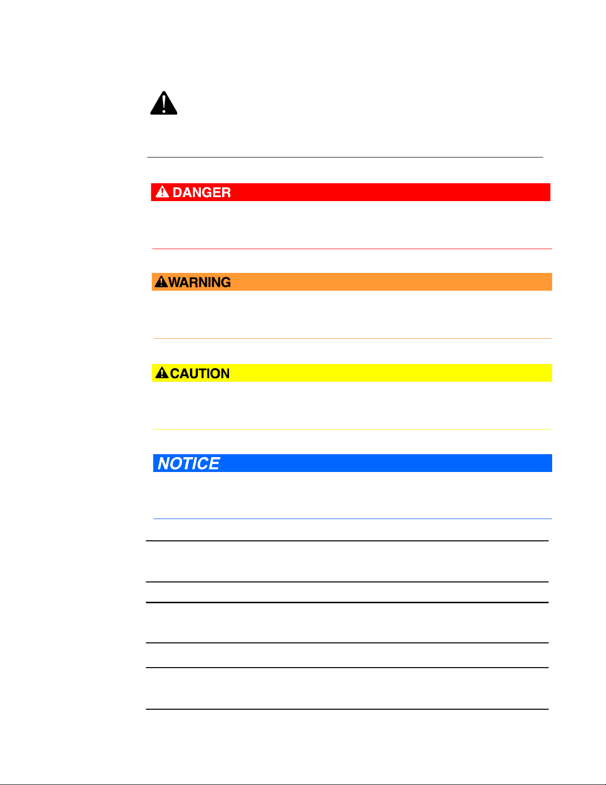
Signal words and symbols
This is a safety alert symbol. It is used to alert you to potential physical injury hazards. Obey
all safety messages that follow this symbol to avoid possible injury or death.
Safety alert symbol
Danger indicates a hazardous situation which, if not avoided, will result in death or serious
injury.
Warning indicates a hazardous situation which, if not avoided, could result in death or serious
injury.
Caution indicates a hazardous situation which, if not avoided, could result in minor or
moderate injury.
Caution indicates a hazardous situation which, if not avoided, could result in minor or
moderate injury.
Pay special attention to the following signal words, safety alert symbols and statements:
Important
Important is a statement the user needs to know and consider.
Tip
Tip provides information or suggestions for improved efficiency or best results.
Note
Note is a “general by-the-way” content not essential to the main flow of information.
Page 5

Important safety instructions
Installing, operating or maintaining a Daniel product improperly could lead to serious injury or
death from explosion or exposure to dangerous substances. To reduce this risk:
• Comply with all information on the product, in this manual, and in any local and national
codes that apply to the product.
• Do not allow untrained personnel to work with this product.
• Use Daniel parts and work procedures specified in this manual.
Daniel Measurement and Control, Inc. (Daniel) designs, manufactures and tests products to
function within specific conditions. Because these products are sophisticated technical
instruments, it is important that the owner and operation personnel strictly adhere both to the
information printed on the product and to all instructions provided in this manual prior to
installation, operation, and maintenance.
Daniel also urges you to integrate this manual into your training and safety program.
BE SURE ALL PERSONNEL READ AND FOLLOW THE INSTRUCTIONS IN THIS MANUAL AND ALL
TICES AND PR
NO
ODUCT WARNINGS.
Product owners (Purchasers):
• Use the correct product for the environment and pressures present. See technical data
or product s
Daniel representative.
• In
• To ensure safe and proper performance, only informed and trained personnel should
• Verify that this is the correct instruction manual for your Daniel product. If this is not
• S
• If you resell or transfer this product, it is your responsibility to forward this instruction
• ALWAYS READ AND FOLLOW THE INSTALLATION, OPERATIONS, MAINTENANCE AND
• Do not us
form and train all personnel in the proper install
this product.
install, o
the correc
the correct manual from:
ave this instruction manual for future reference.
manua
TROUBLE
result in property damage and/or serious personal injury or death.
pecifications for limitations. If you are unsure, discuss your needs with your
ation, operation, and maintenance of
perate, repair and maintain this product.
t documentation, contact Daniel at 1-713-827-6314. You may also download
http://www.daniel.com
l along with the product to the new owner or transferee.
SHOOTING MANUALS AND ALL PRODUCT WARNINGS AND INSTRUCTIONS.
e this equipment for any purpose other than its intended service. This may
Page 6

Product Operation Personnel:
• To prevent personal injury, personnel must follow all instructions of this manual prior to
and during
• Follow all warnings, cautions, and notices marked on, and supplied with, this product.
• Verify that this is the correct instruction manual for your Daniel product. If this is not
correc
the
the correct manual from:
operation of the product.
t documentation, contact Daniel at 1-713-827-6314. You may also download
http://www.daniel.com
• R
• If you do not understand an instruction, or do not feel comfortable following the
• Install this product as specified in the INSTALLA
• Follow all instructions during the installation, operation, and maintenance of this
• Co
• Ensure that
• Use only replacement parts specified by Daniel. Unauthorized parts and procedures can
• S
ead and understand all instructions and operating procedures for this product.
tions, contact your Daniel representative for clarification or assistance.
instruc
TION section of this manual per
applicable local and national codes.
product.
nnect the product to the appropriate pressure and e
where applicable.
all connections to pressure and electrical sources are secure prior to and
during equipment operation.
t this product's performance, safety, and invalidate the warranty. "Look-a-like"
affec
substitutions may result in deadly fire, explosion, release of toxic substances or
improper operation.
ave this instruction manual for future reference.
lectrical sources when and
Page 7

Notice
THE CONTENTS OF THIS PUBLICATION ARE PRESENTED FOR INFORMATIONAL PURPOSES ONLY,
AND WHILE EVERY EFFORT HAS BEEN MADE TO ENSURE THEIR ACCURACY, THEY ARE NOT TO
BE CONSTRUED AS WARRANTIES OR GUARANTEES, EXPRESSED OR IMPLIED, REGARDING THE
PRODUCTS OR SERVICES DESCRIBED HEREIN OR THEIR USE OR APPLICABILITY. ALL SALES ARE
GOVERNED BY DANIEL'S TERMS AND CONDITIONS, WHICH ARE AVAILABLE UPON REQUEST. WE
RESERVE THE RIGHT TO MODIFY OR IMPROVE THE DESIGNS OR SPECIFICATIONS OF SUCH
PRODUCTS AT ANY TIME.
DANIEL DOES NOT ASSUME RESPONSIBILITY FOR TH
ANY PRODUCT. RESPONSIBILITY FOR PROPER SELECTION, USE AND MAINTENANCE OF ANY
DANIEL PRODUCT REMAINS SOLELY WITH THE PURCHASER AND END-USER.
TO THE BEST OF DANIEL'S KNOWLEDGE THE INFORMATION HEREIN IS COMPLETE AND
CCURATE. D
A
WARRANTIES OF MERCHANTABILITY AND FITNESS FOR A PARTICULAR PURPOSE WITH RESPECT
TO THIS MANUAL AND, IN NO EVENT, SHALL DANIEL BE LIABLE FOR ANY INCIDENTAL, PUNITIVE,
SPECIAL OR CONSEQUENTIAL DAMAGES INCLUDING, BUT NOT LIMITED TO, LOSS OF
PRODUCTION, LOSS OF PROFITS, LOSS OF REVENUE OR USE AND COSTS INCURRED INCLUDING
WITHOUT LIMITATION FOR CAPITAL, FUEL AND POWER, AND CLAIMS OF THIRD PARTIES.
PRODUCT NAMES USED HEREIN ARE FOR MANUFACTURER OR SUPPLIER IDENTIFICATION ONLY
MAY BE T
AND
ANIEL MAKES NO WARRANTIES, EXPRESSED OR IMPLIED, INCLUDING THE IMPLIED
RADEMARKS/REGISTERED TRADEMARKS OF THESE COMPANIES.
E SELEC
TION, USE OR MAINTENANCE OF
Page 8

Warranty and Limitations
1. LIMITED WARRANTY: Subject to the limitations contained in Section 2 herein, Daniel Measurement &
Control, Inc. ("Daniel") warrants that the licensed firmware embodied in the Goods will execute the
programming instructions provided by Daniel, and that the Goods manufactured by Daniel will be free from
defects in materials or workmanship under normal use and care and Services will be performed by trained
personnel using proper equipment and instrumentation for the particular Service provided. The foregoing
warranties will apply until the expiration of the applicable warranty period. Goods are warranted for twelve
(12) months from the date of initial installation or eighteen (18) months from the date of shipment by Daniel,
whichever period expires first. Consumables and Services are warranted for a period of 90 days from the date
of shipment or completion of the Services. Products purchased by Daniel from a third party for resale to Buyer
("Resale Products") shall carry only the warranty extended by the original manufacturer. Buyer agrees that
Daniel has no liability for Resale Products beyond making a reasonable commercial effort to arrange for
procurement and shipping of the Resale Products. If Buyer discovers any warranty defects and notifies Daniel
thereof in writing during the applicable warranty period, Daniel shall, at its option, correct any errors that are
found by Daniel in the firmware or Services or repair or replace F.O.B. point of manufacture that portion of the
Goods or firmware found by Daniel to be defective, or refund the purchase price of the defective portion of the
Goods/Services. All replacements or repairs necessitated by inadequate maintenance, normal wear and usage,
unsuitable power sources or environmental conditions, accident, misuse, improper installation, modification,
repair, use of unauthorized replacement parts, storage or handling, or any other cause not the fault of Daniel
are not covered by this limited warranty, and shall be at Buyer's expense. Daniel shall not be obligated to pay
any costs or charges incurred by Buyer or any other party except as may be agreed upon in writing in advance
by Daniel. All costs of dismantling, reinstallation and freight and the time and expenses of Daniel's personnel
and representatives for site travel and diagnosis under this warranty clause shall be borne by Buyer unless
accepted in writing by Daniel. Goods repaired and parts replaced by Daniel during the warranty period shall be
in warranty for the remainder of the original warranty period or ninety (90) days, whichever is longer. This
limited warranty is the only warranty made by Daniel and can be amended only in a writing signed by Daniel.
THE WARRANTIES AND REMEDIES SET FORTH ABOVE ARE EXCLUSIVE. THERE ARE NO REPRESENTATIONS OR
WARRANTIES OF ANY KIND, EXPRESS OR IMPLIED, AS TO MERCHANTABILITY, FITNESS FOR PARTICULAR
PURPOSE OR ANY OTHER MATTER WITH RESPECT TO ANY OF THE GOODS OR SERVICES. Buyer acknowledges
and agrees that corrosion or erosion of materials is not covered by this warranty.
LIMITATION OF REMEDY AND LIABILITY: DANIEL SHALL NOT BE LIABLE FOR DAMAGES CAUSED BY DELAY IN
2.
PERFORMANCE. THE REMEDIES OF BUYER SET FORTH IN THIS AGREEMENT ARE EXCLUSIVE. IN NO EVENT,
REGARDLESS OF THE FORM OF THE CLAIM OR CAUSE OF ACTION (WHETHER BASED IN CONTRACT,
INFRINGEMENT, NEGLIGENCE, STRICT LIABILITY, OTHER TORT OR OTHERWISE), SHALL DANIEL'S LIABILITY TO
BUYER AND/OR ITS CUSTOMERS EXCEED THE PRICE TO BUYER OF THE SPECIFIC GOODS MANUFACTURED OR
SERVICES PROVIDED BY DANIEL GIVING RISE TO THE CLAIM OR CAUSE OF ACTION. BUYER AGREES THAT IN NO
EVENT SHALL DANIEL'S LIABILITY TO BUYER AND/OR ITS CUSTOMERS EXTEND TO INCLUDE INCIDENTAL,
CONSEQUENTIAL OR PUNITIVE DAMAGES. THE TERM "CONSEQUENTIAL DAMAGES" SHALL INCLUDE, BUT NOT
BE LIMITED TO, LOSS OF ANTICIPATED PROFITS, REVENUE OR USE AND COSTS INCURRED INCLUDING
WITHOUT LIMITATION FOR CAPITAL, FUEL AND POWER, AND CLAIMS OF BUYER'S CUSTOMERS.
Page 9

Daniel 3812 Liquid Ultrasonic Flow Meter Installation Manual Table of Contents
3-9000-765 Rev H June 2017
Contents
Daniel customer service
Signal words and symbols
Important safety instructions
Notice
Warranty and Limitations
Section 1: Introduction
1.1 Typical Applications .................................................................................... 1
1.2 Features and benefits .................................................................................. 2
1.3 Acronyms, abbreviations and definitions ....................................................... 3
1.4 Daniel MeterLink software ...........................................................................5
1.5 Daniel 3812 Liquid Ultrasonic Flow meter design ........................................... 6
1.6 Meter specifications ................................................................................. 13
1.7 Pre-installation considerations ................................................................... 17
1.8 Safety ...................................................................................................... 17
1.9 Daniel 3812 Certifications and Approvals .................................................... 19
1.10 FCC compliance ....................................................................................... 19
Section 2: Mechanical installation
2.1 Meter piping, lifting and mounting ............................................................. 23
2.2 Piping recommendations ........................................................................... 30
2.3 Meter safety for hoist rings and lifting slings ............................................... 34
2.3.1 Use of appropriate safety engineered swivel hoist rings in
meter end fl
2.3.2 Appropriately rated lifting slings.................................................................. 42
2.4 Mounting requirements in heated or cooled pipelines .................................. 45
anges........................................................................................ 35
Section 3: Electrical installation
3.1 Cable length TTL mode .............................................................................. 47
3.2 Cable length Open Collector mode ............................................................. 47
3.3 Grounding meter electronics housing ......................................................... 48
3.4 Conduit seals ............................................................................................ 49
3.4.1 Startup for systems using explosion-proof conduit ........
3.4.2 Startup for systems that use flame-proof cable ........................................... 51
3.5 Wiring and I/O .......................................................................................... 52
3.5.1 CPU Module labeling and LED indicators ..................................................... 53
.............................. 50
Table of Contents i
Page 10

Table of Contents Daniel 3812 Liquid Ultrasonic Flow Meter Installation Manual
June 2017 3-9000-765 Rev H
3.6 I/O connections ......................................................................................... 57
3.6.1 Frequency/Digital outputs ...........................................................................58
3.6.2 Analog input settings...................................................................................62
3.6.3 Analog output settings ................................................................................62
3.6.4 Digital Input.................................................................................................62
3.6.5 DHCP server switch settings.........................................................................62
3.6.6 Configuration protect switch settings .................
3.6.7 External power source connection and fuse ........
3.7 Security seal installation ............................................................................64
3.7.1 Direct or remote mount transmitter electronics enclosure seal
3.7.2 Base Enclosure Security Seals .......................................................................66
3.7.3 Seal the Junction Box remote mount electronics option ...............................67
3.7.4 Bolted band shroud security seals ................................................................68
3.7.5 Clamped band shroud security seals ............................................................69
3.7.6 Split shroud security seals ............................................................................70
3.7.7 Latched band shroud security seals..............................................................71
3.7.8 Seal conduit ports ........................................................................................73
.........................................63
.........................................63
....................64
Section 4: Configuration
4.1 Daniel MeterLink setup ..............................................................................75
4.2 Field Setup Wizard..................................................................................... 76
4.3 Using AMS Device Manager to configure the meter ...................................... 80
4.4 Using a Field Communicator to configure the meter .................................... 95
4.5 Security seals for the meter ........................................................................ 98
Appendix A: Engineering drawings
A.1 Daniel 3812 Liquid Ultrasonic Flow Meter drawings ..........................................................99
Appendix B: Open source licenses
B.1 GNU General Public License............................................................................................. 102
B.2 GNU Lesser General Public License .................................................................................. 113
B.3 BSD Open Source License................................................................................................ 117
B.4 M.I.T License ................................................................................................................... 118
Appendix C Index
C.1 Manual Index .................................................................................................................. 119
ii Table of Contents
Page 11

Daniel 3812 Liquid Ultrasonic Flow Meter Installation Manual Installation Manual List of Tables
3-9000-765 Rev H June 2017
List of Tables
Table 1-1 Acronyms, abbreviations and definitions ........................................................................... 3
Table 1-2 Meter specifications........................................................
Table 2-1 3812 Ultrasonic Meter shrouds options per ANSI pressure rating ..................................... 29
................................................. 13
Table 2-2 Piping recommendation for uni-directional or bi-directional flow .
Table 2-3 Hoist ring part number lookup table ................................................................................ 41
Table 2-4 Hoist ring lookup table for Daniel Model 3812 Liquid Ultrasonic Flow Meters................... 41
Table 3-1 Configurations for open collector frequency outputs....................................................... 47
Table 3-2 CPU Module labeling and LED functions ........................................................................... 54
Table 3-3 Ethernet cable to PC communication............................................................................... 55
Table 3-4 Serial Port A parameters................................................................................................... 56
Table 3-5 Frequency/Digital Outputs possible configurations.......................................................... 60
Table 3-6 DHCP server switch settings............................................................................................. 62
gs ......
Table 3-7 Configuration protect switch settin
Table 4-1 Local display labels, descriptions and valid units............................................................... 77
Table B-1 Open source licences .................................................................................................... 101
........................................................................ 63
................................... 33
List of Tables i
Page 12

List of Tables Daniel 3812 Liquid Ultrasonic Flow Meter Installation Manual Installation Manual
June 2017 3-9000-765 Rev H
ii List of Tables
Page 13

Daniel 3812 Liquid Ultrasonic Flow Meter Installation Manual Installation Manual List of Figures
3-9000-765 Rev H June 2017
List of Figures
Figure 1-1 Daniel MeterLink download and registration ................................................................ 5
Figure 1-2 Direct mount electronics assembly with split shroud ....
Figure 1-3 Direct mount electronics with latched single band shro
Figure 1-4 Direct mount electronics with bolted single band shrouds and local display ................ 8
Figure 1-5 Direct mount electronics assembly with clamped band shrouds ...
Figure 1-6 Remote mount electronics assembly with clamped band shrouds .............................. 10
Figure 1-7 Remote mount electronics assembly with split shrouds ............................................. 11
Figure 1-8 Optional local display and glass endcap ...................................................................... 12
Figure 2-1 Direct mount meter electronics assembly with spli
Figure 2-2 Remote mount meter electronics assembly with split shroud ..................................... 27
Figure 2-3 Direct mount meter electronics with bolted band
Figure 2-4 Direct mount meter electronics assembly with clamped band shro
Figure 2-5 Piping recommendations unidirectional flow ............................................................. 31
Figure 2-6 Piping recommendations bidirectional flow................................................................ 32
Figure 2-7 Meter end flange with tapped flat-counterbore hole for hoist ring ............................ 35
Figure 2-8 Safety approved hoist ring and non-compliant eye
Figure 2-9 90 Degree angle between slings ................................................................................. 37
Figure 2-10 Sling contacting electronics enclosure........................................................................ 38
Figure 2-11 Correct sling attachment ............................................................................................ 43
Figure 2-12 Incorrect sling attachment.......................................................................................... 44
Figure 3-1 Transmitter Electronics Enclosure internal chassis ground .......................................... 48
................................................ 6
uds and remote display............ 7
................................ 9
t shroud..
shrouds ......................................... 28
bolt ...........
...................................... 26
uds....................... 29
................................... 36
Figure 3-2 External ground lug .................................................................................................... 49
Figure 3-3 CPU Module labeling and LED indicators ..................................................................... 53
Figure 3-4 PC to meter serial connection wiring........................................................................... 57
Figure 3-5 CPU Module I/O connections...................................................................................... 57
Figure 3-6 CPU Module - Frequency/Digital outputs common ground ........................................ 61
Figure 3-7 CPU Module power source connections ..................................................................... 63
Figure 3-8 Transmitter electronics enclosure security latch ........................................................ 64
Figure 3-9 Direct or remote mount Tra
Figure 3-10 Base Enclosure security seals ...................................................................................... 66
Figure 3-11 3812 Remote mount transmitter electronics option.......
Figure 3-12 Bolted band shroud security seals - bottom view ........................................................ 68
Figure 3-13 Clamped shroud security seals ................................................................................... 69
List of Figures iii
nsmitter Electronics
Enclosure security seals ................... 65
............................................ 67
Page 14

List of Figures Daniel 3812 Liquid Ultrasonic Flow Meter Installation Manual Installation Manual
June 2017 3-9000-765 Rev H
Figure 3-14 Split shroud security seals ...........................................................................................70
Figure 3-15 Latched band shroud assembly ...................................................................................71
Figure 3-16 Shroud latch holes for security wire seals.....................................................................72
Figure 4-1 AMS Device Description search ...................................................................................80
Figure 4-2 AMS file download complete ......................................................................................81
Figure 4-3 AMS Device Manager .................................................................................................82
Figure 4-4 AMS Device Manager - Overview ...............................................................................82
Figure 4-5 AMS Device Manager - Guided Setup ..........................................................................83
Figure 4-6 AMS Device Manager - Service Tools All Variables status indicators .............................85
Figure 4-7 Display Meter K-Factors ..............................................................................................85
Figure 4-8 AMS Device Manager - Configure Manual Setup..........................................................86
Figure 4-9 Gating configuration parameter Edge gated, active
high ......
Figure 4-10 Gating configuration parameter Edge gated, active low..
......................................88
............................................88
Figure 4-11 Gating configuration parameter State gated, active high...
Figure 4-12 Gating configuration parameter State gated, active low .
.........................................88
............................................89
Figure 4-13 Configure Flow Analysis Alert .....................................................................................89
Figure 4-14 AMS Device Manager - Service Tools Alerts .................................................................91
Figure 4-15 Configuration changes dialog .....................................................................................91
Figure 4-16 AMS Device Manager - Service Tools ..........................................................................92
Figure 4-17 AMS Device Manager - Service Tools All Variables ......................................................93
Figure 4-18 AMS Device Manager - Service Tools Trends ..............................................................94
Figure 4-19 3812 transmitter field wiring conduit
entries .......
Figure 4-20 Field Communicator wiring diagram for the 3810 Series electronics
.......................................................96
..........................97
iv List of Figures
Page 15

Daniel 3812 Liquid Ultrasonic Flow Meter Installation Manual Section 1: Introduction
3-9000-765 Rev H June 2017
Section 1: Introduction
Daniel 3812 Liquid Ultrasonic Flow Meters have direct mount or remote mount electronic
options and various configurations that meet a broad range of customer requirements. Each
meter comes fully assembled from Daniel Measurement and Control, Inc. and all parts and
assemblies are tested prior to shipment. Refer to the following documents for additional details:
• P/N 3-9000-761 HART® Field Device Specification for Liquid Ultrasonic Flow Meters
• P/N 3-9000-763 D
Meters
• P/N 3-9000-767 D
and Troubleshooting Manual
The Daniel 3812 Liquid Ultrasonic Flow Meter tech
measurement and check metering applications as shown below.
aniel MeterLink Software for Daniel Gas and Liquid Ultrasonic Flow
aniel Model 3812 Liquid Ultrasonic Flow Meter Maintenance
1.1 Typical Applications
• Allocation measurement
• Check mete
• Leak detection
• Line balancing
• Batch control
• Loading and off loading
• Offshore
- FPSO (Floating Production, Storage and Offshore Loading)
- Offshore Platforms
- Barges
• Pipeli
ring
nes
nology can be applied to allocation
- Crude Oil pipeli
- Refined product pipelines
• Ter m in al s
- Loading and off-loading (Ship, barge, truck, railcar, etc…)
- Ta nk Far ms
• Cavern Storage
Typical Applications 1
nes
Page 16

Section 1: Introduction Daniel 3812 Liquid Ultrasonic Flow Meter Installation Manual
June 2017 3-9000-765 Rev H
1.2 Features and benefits
• Explosion-proof transmitter electronics enclosure with CPU Module, Power Supply,
Intrinsic Safety Barrier Module
• Intrinsically safe transducer electronics enclosure with the Acquisition Module
• Daniel MeterLink (software for Daniel Ultrasonic Flow Meters)
®
• HART
architecture
• Direct mount or remote mount options electronics
• Reduce unaccounted measurement
• Increase energy savings
• Replaceable transducers while under pressure
• Extensive self diagnostics
• Immedia
• Auto-detected ASCII/RTU Modbus communications protocol
• Interchangeable electronics modules
• Internet-ready communications
and AMS Suite: Intelligent Device Manager communications for PlantWebTM
te alarm
reporting
• Ethernet access
• Modbus T
• On
• Analog pressure and temperature inputs
• Local display and glass endcap (optional)
or ot
her features and benefits refer to the product datasheet at
F
http://www2.emersonprocess.com/EN-US/BRANDS/DANIEL/FLOW/Pages/Flow.aspx
CP/IP
-board LED status indicators
2 Features and benefits
Page 17
Daniel 3812 Liquid Ultrasonic Flow Meter Installation Manual Section 1: Introduction
3-9000-765 Rev H June 2017
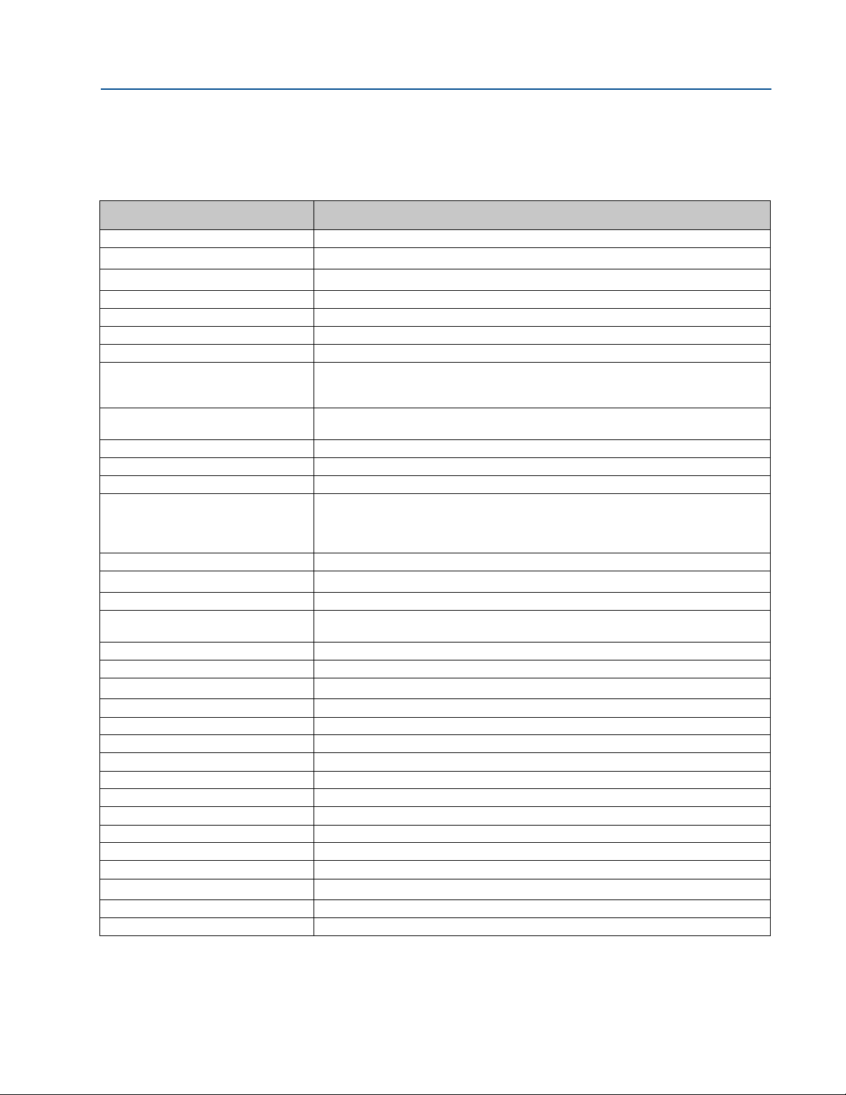
1.3 Acronyms, abbreviations and definitions
Table 1-1 Acronyms, abbreviations and definitions
Acronym or abbreviation Definition
° degree (angle)
o
C
o
F
ADC analog-to-digital converter
AI analog input
AMS® Device Manager Asset Management Software - Device Manager
AO analog output
ASCII MODBUS A Modbus protocol message framing format in which ASCII characters are used to
boolean a type of data point that can only take on values of TRUE or F
bps bits per second (baud rate)
cPoise centipoise (viscosity unit)
CPU central processing unit
CTS Clear-to-Send; the RS-232C handshaking signal input to a transmitter indicating that
DAC Digital-to-Analog Converter
Daniel MeterLink
DI digital input
Direct Mount Transmitter electronics enclosure and base electronics enclosure is directly mounted
DO digital output
DHCP Dynamic Host Configuration Protocol
dm
ECC Error Correction Code
EEPROM Electrically-Erasable, Programmable Read-Only Memory
Flash non-volatile, programmable read-only memory
FODO output that is user configurable as either a frequency or digital output
HART® Communication Protocol Highway Addressable Remote Transducer communications protocol
hr hour (time unit)
Hz Hertz (cycles per second, frequency unit)
I/O Input/Output
IS Intrinsically Safe
K Kelvin (temperature unit)
kHz
LAN Local Area Network
LED light-emitting diode
TM
degrees celsius (temperature unit)
degrees fahrenheit (temperature unit)
eate the beginning and end of the frame. ASCII stands for American Standard
delin
Code for Information Interchange.
ALSE (generally TRUE is
represented by a value of 1, FALSE is represented by a value of 0)
it is okay
Generally, the Request-to-Send (RTS) output from a receiver is input to the Clear-toSend (CTS) input of a transmitter.
Daniel ultrasonic meter interface software
to
decimeter (10
kilohertz (10
to transmit data – i.e., the corresponding receiver is ready to receive data.
meter bo
dy
-1
meters, length unit)
3
cycles per second, frequency unit)
Acronyms, abbreviations and definitions 3
Page 18

Section 1: Introduction Daniel 3812 Liquid Ultrasonic Flow Meter Installation Manual
June 2017 3-9000-765 Rev H
Table 1-1 Acronyms, abbreviations and definitions
Acronym or abbreviation Definition
m meter (length unit)
3
m
/d
3
m
/h
3
m
/s
mA milliamp (current unit)
MAC Address Media Access Control (Ethernet Hardware Address -EHA)
microinch (
μinch)
micron
MMU Memory Management Unit
MPa
N/A not applicable
3
/h
Nm
NOVRAM non-volatile random access memory
Pa Pascal, equivalent to 1 newton per square meter (pressure unit)
Pa⋅s Pascal Second (viscosity unit)
PC Personal Computer
PFC peripheral field connection (board)
P/N part number
PS power supply (board)
psi pounds per square inch (pressure unit)
psia pounds per square inch absol
psig pounds per square inch gage (pressure unit)
R Radius
rad radian (angle)
RAM Random Access Memory
Remote Mount Option Detaching the transmitter electronics enclosure and base electronics enclosure from
RTS Request-to-Send; the RS-232C handshaking signal output by a receiver when it is
RTU MODBUS A Modbus protocol framing format in which elapsed time between received charac-
s second (time unit, metric)
SDRAM Synchronous Dynamic Random Access Memory
sec second (time unit, U.S. Customary)
TCP/I P Transmission Control Protocol/Internet Protocol
time_t seconds since Epoch (00:00:00 UTC Jan. 1, 1970) (time unit)
UDP User Datagram Protocol
U.L. Underwriters Laboratories, Inc. - product safety testing
V volts (electric potential unit)
cubic meters per day (volumetric flow rate)
cubic meters per hour (volumetric flow rate)
cubic meters per second (volumetric flow rate)
-6
microinch (10
in)
micrometer (10-6 m)
6
Megapascal (equivalent to 10
Pascal) (pressure unit)
normal cubic meters per hour
ute (pressure unit)
ter body and moun
me
ting and affixing them with the mounting bracket to a pole or
other structure.
ready to re
ceive data
ters is used to separate messages. RTU stands for Remote Terminal Unit.
and certification organization
4 Acronyms, abbreviations and definitions
Page 19

Daniel 3812 Liquid Ultrasonic Flow Meter Installation Manual Section 1: Introduction
3-9000-765 Rev H June 2017
Table 1-1 Acronyms, abbreviations and definitions
Acronym or abbreviation Definition
W watts (power unit)
Acronyms, abbreviations and definitions 5
Page 20
Section 1: Introduction Daniel 3812 Liquid Ultrasonic Flow Meter Installation Manual
June 2017 3-9000-765 Rev H
1.4 Daniel MeterLink software
Daniel MeterLink software has robust features for setting communications parameters,
calibrating your meter, collecting logs and reports and monitoring the meter health and alarm
statuses. Daniel MeterLink may be downloaded at no charge from:
http://www2.emersonprocess.com/en-US/brands/danie
Figure 1-1 Daniel MeterLink download and registration
l/Flow/ultrasonics/P
ages/MeterLink.aspx
1.
2. Click the Order No
3. Click Next to go
4. Click Comple
5. Click Save.
6 Daniel MeterLink software
From the right panel under Quick Links, click the MeterLin
link.
w button to complete the Online registration form.
to the order confirmation page.
te Order.
You will receive a conformation email with a hyperlink directing you to the download
site. Click the
link provided.
k Registration and Download
Page 21
Daniel 3812 Liquid Ultrasonic Flow Meter Installation Manual Section 1: Introduction
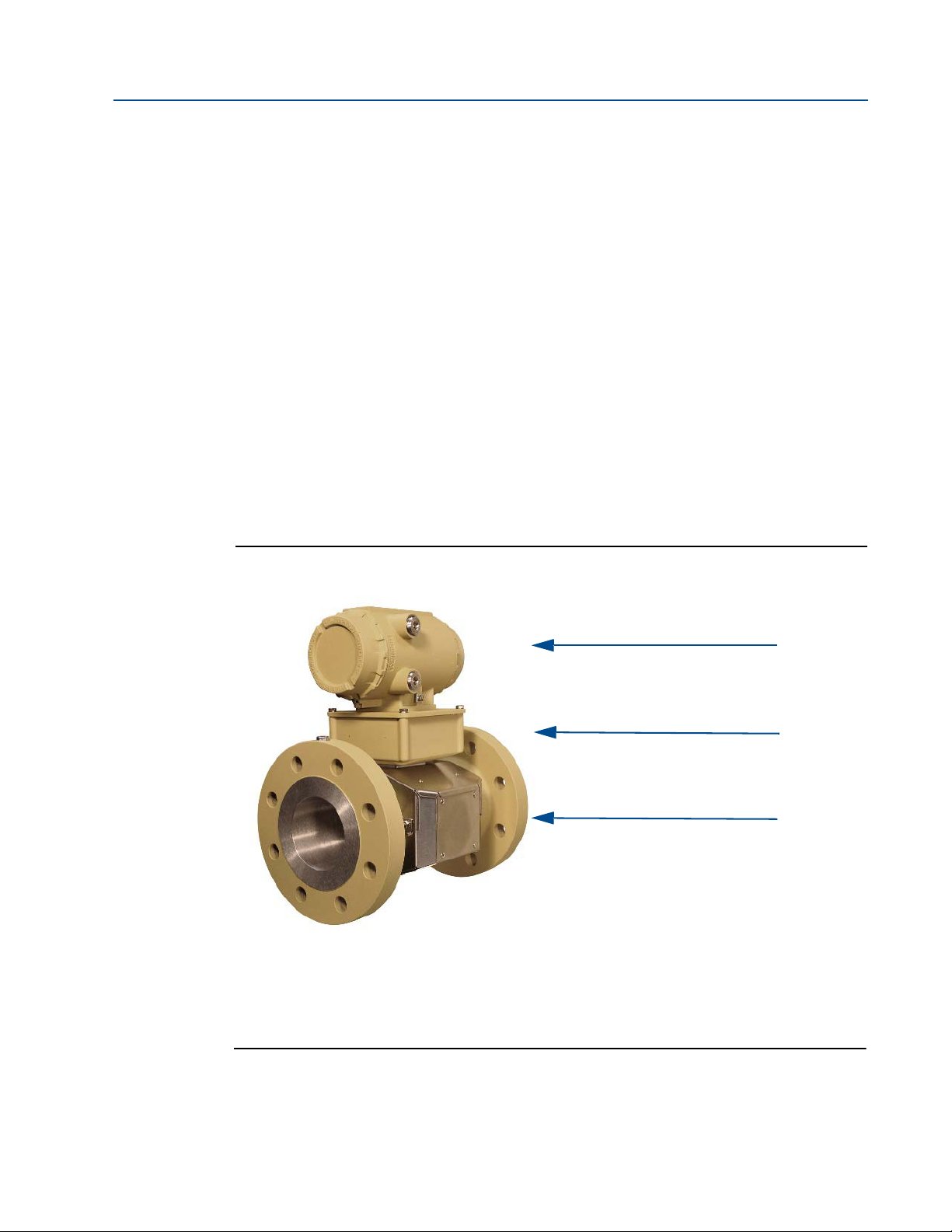
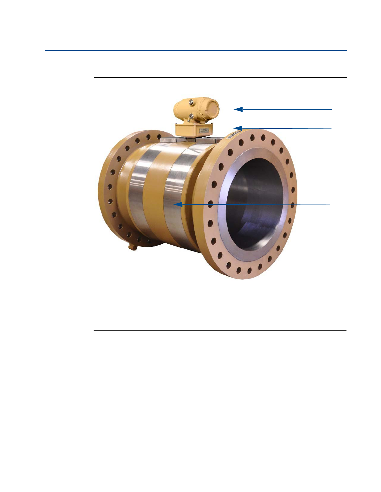
A. Explosion-proof transmitter enclosure (CPU Module, Power Supply, I.S. Barrier Board,
B. Intrinsically-safe base enclosure includes Acquisition Module
C. Meter - body and split shroud for transducers and cables assemblies
A.
B.
C.
Backplane board, and optional LCD Board with glass endcap)
3-9000-765 Rev H June 2017
Refer to the Daniel MeterLink Software for Gas and Liquid Ultrasonic Meters Quick Start Manual
(P/N 3-9000-763) for installation instructions and setup for initi
download the manual from the Daniel MeterLink web page:
al communications. You may
http://www2.emersonprocess.com/en-US/brands/daniel/Flow/ultrasonics/P
ages/MeterLink.aspx
1.5 Daniel 3812 Liquid Ultrasonic Flow meter design
TheDaniel 3812 Liquid Ultrasonic Flow Meter designs include a direct or remote mount
electronics option and depending on the meter’s outside diameter, have a shroud cover
protecting the transducers and cable assemblies. See Table 2-1 and the list below for meter
body shroud types.
Shroud options are:
• sp
• bolted band shroud
• latched single band shroud
• clamped band shroud
Figure
lit shroud
1-2 Direct mount electronics assembly with split shroud
Daniel 3812 Liquid Ultrasonic Flow meter design 7
Page 22
Section 1: Introduction Daniel 3812 Liquid Ultrasonic Flow Meter Installation Manual
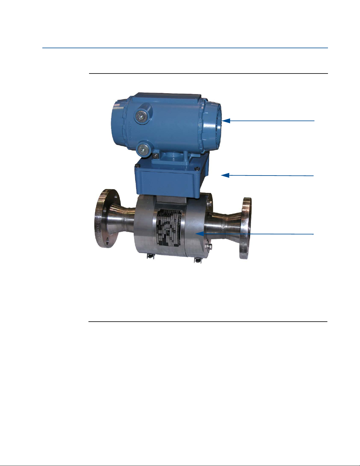
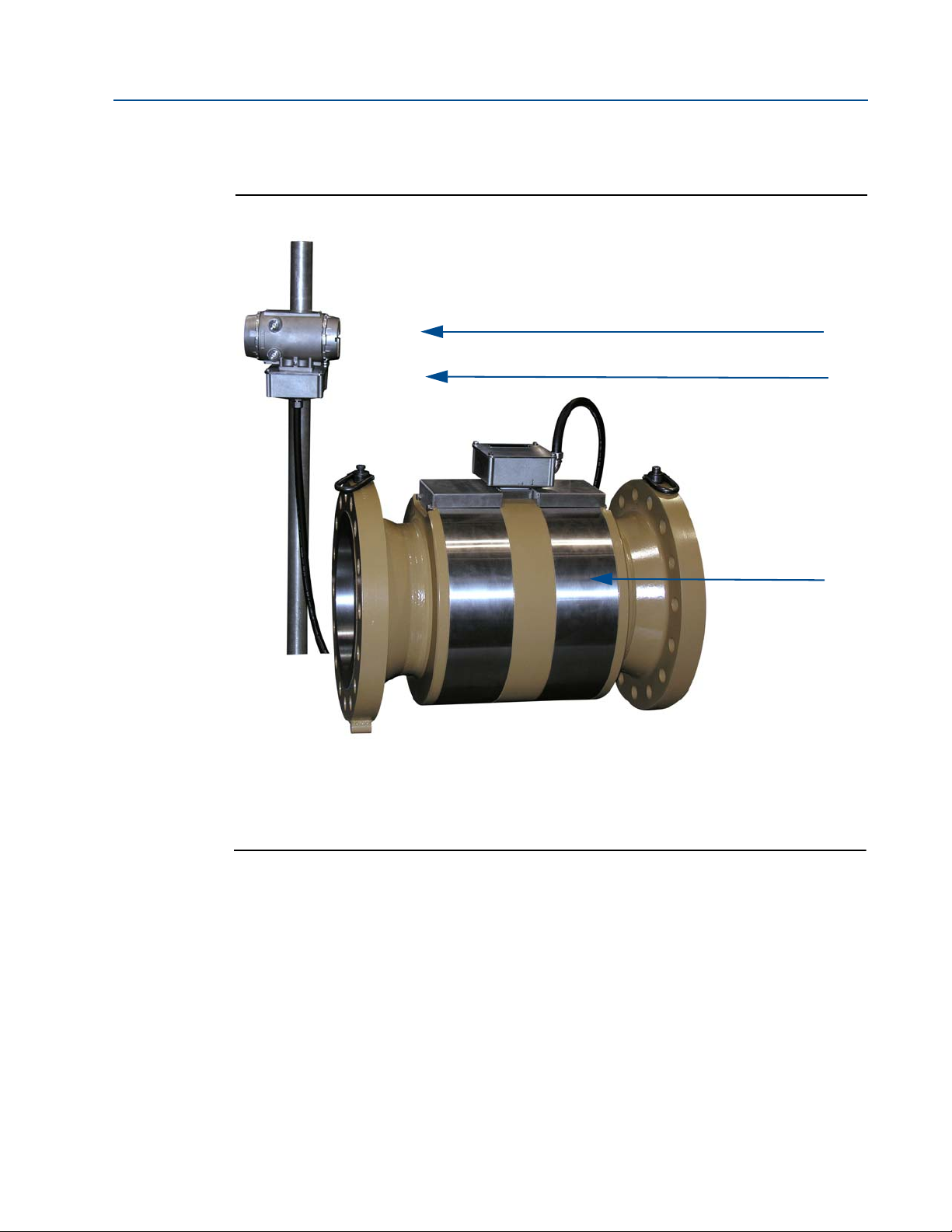
A. Explosion-proof transmitter enclosure (CPU Module, Power Supply, I.S. Barrier Board,
B. Intrinsically-safe base enclosure includes Acquisition Module
C. Meter - body and latched band shrouds for transducers and cable assemblies
A.
B.
C.
Backplane board, and optional LCD Board with glass endcap)
June 2017 3-9000-765 Rev H
Figure 1-3 Direct mount electronics with latched single band shrouds and remote display
8 Daniel 3812 Liquid Ultrasonic Flow meter design
Page 23
Daniel 3812 Liquid Ultrasonic Flow Meter Installation Manual Section 1: Introduction
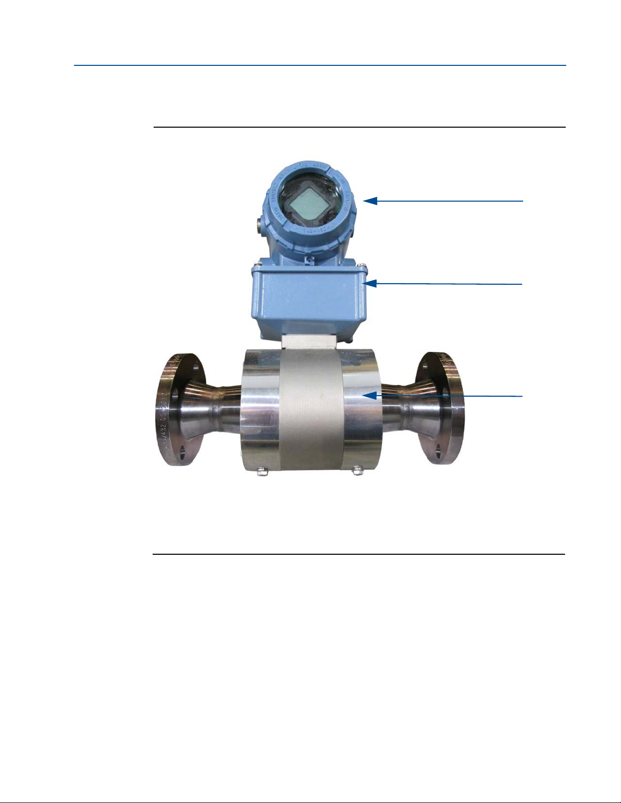
A. Explosion-proof transmitter enclosure (CPU Module, Power Supply, I.S. Barrier Board,
B. Intrinsically-safe base enclosure includes Acquisition Module
C. Meter - body and latched band shrouds for transducers and cable assemblies
A.
B.
C.
Backplane board, and optional LCD Board with glass endcap)
3-9000-765 Rev H June 2017
Figure 1-4 Direct mount electronics with bolted single band shrouds and local display
Daniel 3812 Liquid Ultrasonic Flow meter design 9
Page 24
Section 1: Introduction Daniel 3812 Liquid Ultrasonic Flow Meter Installation Manual
A. Explosion-proof transmitter enclosure (CPU Module, Power Supply, I.S. Barrier Board,
B. Intrinsically-safe base enclosure includes Acquisition Module
C. Meter - body and band shrouds for transducers and cable assemblies
A.
B.
C.
Backplane board, optional LCD Board with glass endcap)
June 2017 3-9000-765 Rev H
Figure 1-5 Direct mount electronics assembly with clamped band shrouds
10 Daniel 3812 Liquid Ultrasonic Flow meter design
Page 25
Daniel 3812 Liquid Ultrasonic Flow Meter Installation Manual Section 1: Introduction
A. Explosion-proof transmitter enclosure (CPU Module, Power Supply, I.S. Barrier Board,
B. Intrinsically-safe base enclosure includes Acquisition Module
C. Meter - body and band shrouds for transducers and cable assemblies
A.
B.
C.
Backplane board, and optional LCD Board with glass endcap)
3-9000-765 Rev H June 2017
Figure 1-6 Remote mount electronics assembly with clamped
band shrouds
Daniel 3812 Liquid Ultrasonic Flow meter design 11
Page 26
Section 1: Introduction Daniel 3812 Liquid Ultrasonic Flow Meter Installation Manual
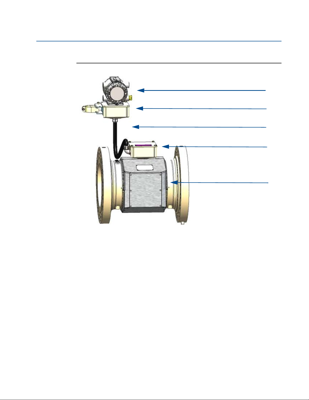
A. Explosion-proof transmitter enclosure (CPU Module, Power Supply, I.S. Barrier Board
B. Intrinsically-safe base enclosure includes Acquisition Module
C. Acquisition cable conduit
A.
B.
E.
D.
C.
D. Junction box
E. Meter - body and split shrouds for transducer and cable assemblies
Backplane board, optional LCD Board with glass endcap)
June 2017 3-9000-765 Rev H
Figure 1-7 Remote mount electronics assembly with split shrouds
12 Daniel 3812 Liquid Ultrasonic Flow meter design
Page 27
Daniel 3812 Liquid Ultrasonic Flow Meter Installation Manual Section 1: Introduction
3-9000-765 Rev H June 2017
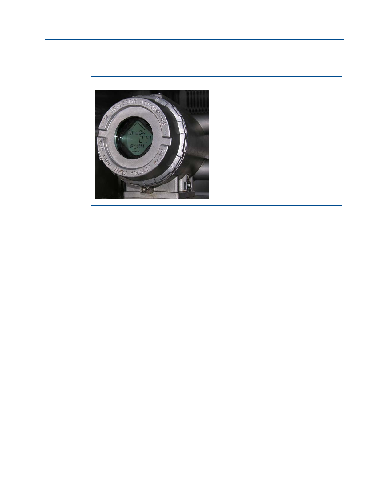
Figure 1-8 Optional local display and glass endcap
The Daniel 3812 Liquid Ultrasonic Flow Meter is a two-path (four transducers) in-line meter
designed to me
asure the difference in signal transit time with and against the flow across one or
more measurement path(s). A signal transmitted in the flow direction travels faster than one
transmitted against the flow direction. Each measurement path is defined by a transducer pair
in which each transducer alternately acts as transmitter and receiver. The meter uses transit
time measurements and transducer location information to calculate the mean velocity.
Computer simulations of various velocity profiles demonstrate that multiple measurement
ths provide an op
pa
timum solution for measuring asymmetric flow. The Daniel 3812 Liquid
Ultrasonic Flow Meter utilizes two cross-bore, parallel-plane measurement paths, offers a high
degree of repeatability, bi-directional measurement and superior low-flow capabilities without
the compromises associated with conventional technologies.
. safet
The Daniel 3812 Liquid Ultrasonic Flow Meter’s U.L
y listing is accomplished through the
combination of an explosion-proof Transmitter Electronics Enclosure that houses the CPU
Module, Power Supply board, I.S. Barrier board, Backplane board and optional LCD Display
board.
NOTE: The op
tional LC
D Display requires firmware v1.04 and Uboot version, January 31, 2013.
The Base Electronics Enclosure is intrinsically safe and houses the Acquisition Module, the
acquisitio
n cable and wiring. The Intrinsically safe transducers and cable assemblies are
designed for Class 1, Division 1, Groups C and D areas without need of further protection when
installed in accordance with the field wiring diagram (refer to Daniel drawing DMC - 004936, see
Appendix A and Section 1.8).
Daniel 3812 Liquid Ultrasonic Flow meter design 13
Page 28
Section 1: Introduction Daniel 3812 Liquid Ultrasonic Flow Meter Installation Manual
ESCAPING FLUIDS HAZARD
The purchaser of the meter is responsible for the selection of Daniel components/seals and materials
compatible with the chemical properties of the measurement fluid.
Failure to select suitable meter components/seals may cause escaping fluids, resulting in injury or equipment
damage.
June 2017 3-9000-765 Rev H
1.6 Meter specifications
Consult your Daniel Sales and Service representative to ensure you purchase the correct
components
Table 1-2 Meter specifications
Liquid Ultrasonic Flow Meter specifications
Meter type Number of paths
Enclosure materials
Enclosure materials
and seals for your application.
• Two path (four transducer) chordal design
• ASTM B26 Gr A356.0 T6 Aluminum
— Chromate conversion coated with a polyurethane enamel
• ASTM A351 Gr CF8M Stainless Steel
— Passivated
Ultrasonic type
• Transit-time based measurement
• Spool piece with integral mount transducers
• ASTM B26 Gr A356.0 T6 Aluminum
— Chromate conversion coated with a polyurethane enamel
• ASTM A351 Gr CF8M Stainless Steel
— Passivated
Meter Performance
Linearity
Repeatability
Velocity range
• ± 0.30% of measured value over a 10:1 turndown (40 to 4 ft/s; 12.2 to 1.2 m/s)
• ±0.10% of reading in the specified velocity range
• 40.0 ft/s (12.2 m/s) (nominal) to 2.0 ft/s (0.6 m/s)
• 48 fps (14.3 m/s) (over-range)
14 Meter specifications
Page 29
Daniel 3812 Liquid Ultrasonic Flow Meter Installation Manual Section 1: Introduction
3-9000-765 Rev H June 2017
Table 1-2 Meter specifications
Body and Flange Pressure
rating range
U.S. Customary Units sizes - 2, 3, 4, 6, 8, 10, 12, 14, 16, 18, 20, 24, 28, 30, and 36 (in)
• ANSI pressure classes 150 and 300, 600, 900 (per ANSI B16.5)
• Carbon Steel
• 316 Stainless Steel
Metric Units sizes
• DN 50, 75, 100, 150, 200, 250, 300, 350, 400, 450, 500, 600, 700, 750, and 900
• PN 20, 50, 100, 150
• Carbon Steel
• 316 Stainless Steel
Meter bore
• Schedule 40 and Schedule 80
Maximum Pressures
• Dependent on operating temperature
Meter Performance (continued)
Flange types ANSI classes - 150, 300, 600 and 900
• Raised face or RTJ
Specific Gravity 0.35 to 1.50
Accuracy Limits Accuracy limits typically are:
• ± 2% without a flow calibration, ± 0.3% with flow calibration
Minimum operating
pressure
• 0 psig
• 0 barg
Electronic specifications
Power Meter
• 10.4 VDC to 36 VDC measured at the meter terminals
• 11 W maximum power consumption
Serial cable
• Belden #9940 or equivalent (22 gauge)
Ethernet cable
• Cat-5 Standard 100Mbps
Frequency (
• 22 AWG wire characteristics are as follows:
Tem p er at u re
flameproof transmitter
electronic enclosure and
base ele
ctronic enclosure
• Ambient: -40
• Storage: -58
Note: The transmitter electronics enclosure and base enclosure must be remote mounted if the
1
— Capacitance (pF/m) 121.397 (conductor to conductor)
— Capacitance (pF/m) 219.827 (conductor to other conductor and shield)
— Resistance (DC) DCR @ 20 °C (Ohm/km) 48.2307
Nominal Outer shield resistance - DCR @ 20°C (Ohm/km) 16.405
— Operating voltage - 300 V RMS (UL AWM Style 2464)
— Current 2.4 Amps per conductor @ 25°C (recommended)
see Table 3-1)
— Capacitance = 20 pF/ft or 20 nF/1000 ft (between two wires)
— Resistance = 0.0168 Ohms/ft or 16.8 Ohms/1000 ft
— Pull-up voltage is 24 VDC
o
F to 140 oF (-40 oC to 60 oC)
o
F to 185 oF (-50 oC to 85 oC)
operating temperature exceeds 140 oF (60 oC).
Meter specifications 15
Page 30
Section 1: Introduction Daniel 3812 Liquid Ultrasonic Flow Meter Installation Manual
June 2017 3-9000-765 Rev H
Table 1-2 Meter specifications
Transducers
• LT-1 0 and LT- 11 Operat ing temper ature range with NBR O -rings
o
F to +275 oF (-50 oC to 135 oC)
-58
• LT-1 0 and LT- 11 Operat ing temper ature range with FKM O -rings
o
-40
F to +302 oF (-40 oC to +150 oC)
ting temperature range of
Acquisition Cable
Note: The process temperature must not exceed the opera
the transducers.
Note: LT-10 transducers are designed for 4 inch to 10 inch meters. LT-11 transducers are designed
for 12 inch
Note: The ultrasonic transducers are not intended for use across boundary walls of different
hazardous area classifications. The transmitter electronics cannot be remote mounted from
a Division 1 classification to a Division 2 area to meet an area classification.
and larger meters.
• Total cable length between the Acquisition Module and ultrasonic transducers must not
exceed 15 feet (4.7 meters) when using the remote mount option (
Communications specifications
Connectivity protocols One serial RS-232/RS-485 port (115 kbps baud rate) (Modbus RTU/ASCII)
• (1) Serial Port A
(RS-232/RS-485 Full Duplex/RS-485 Half Duplex)
One Ethernet Port (TCP/IP) 100 BaseT
• Modbus TCP
Device compatibility
FloBoss 103, FloBoss S600 flow computer, ROC 107
Digital, analog, and frequency inputs
Digital Input(s)
(Selectable)
(1) Single polarity (for flow calibration gating - contact closure)
• Single input for starting and stopping
• Four pulse configurations available
Analog Input(s) (2) 4-20 mA
• AI-1 Temperature
• AI-2 Pressure
Note: The analog-to-digital conversion accuracy is within ±0.05% of full scale over the operating
temperature range.
see Figure 1-7)
Note: AI-1 and AI-2 are electronically isolated and oper
series resistance so HART® Communicators can be connected to configure sensors.
A 24 Volt DC power supply is available to provide power to the sensors.
ate in sink mode. The input contains a
Digital, analog, and frequency outputs
16 Meter specifications
Page 31

Daniel 3812 Liquid Ultrasonic Flow Meter Installation Manual Section 1: Introduction
3-9000-765 Rev H June 2017
Table 1-2 Meter specifications
Frequenc y/Digital
Output(s)
The meter has user-configurable selections for either a frequency output or Digital status (FODO)
(Also see Section 3.6.1)
(3) Frequency/Digital Outputs
• FODO1 (four possible output configurations)
• FODO2(eight possible output configurations)
• FODO3(eight possible output configurations)
Frequency or Digital Output parameter pairs (
Frequency or Digital Outputs (FODO 1) source selections:
see Section 3.6.1)
• (FO1A, DO1A, FO1B, DO1B)
Frequency or Digital Outputs (FODO 2) source selections
• (FO1A, DO1A, FO1B, DO1B, FO2A, DO2A, FO2B, DO2B)
Frequency or Digital Outputs (FODO 3) source selections
• (FO1A, DO1A, FO1B, DO1B, FO2A, DO2A, FO2B, DO2B)
Mode options:
• Open Collector (requires external excitation supply voltage and pull-up resistor)
• TTL (internally powered by the meter 0-5 VDC signal)
Channel B Phase options:
• Lag forward, Lead reverse (Phase B lags Phase A while reporting forward flow, leads Phase A
while reporting reverse flow)
• Lead forward, Lag reverse (Phase B leads Phase A while reporting forward flow, lags Phase A
while reporting reverse flow)
Phase A and Phase B output (based on flow direction)
• Reverse flow - output only reports flow in the reverse direction. For frequency outputs, Phase
B of the output is 90 degrees out of phase with Phase A.
• Forward flow - output only reports flow in the forward direction. For frequency outputs, Phase
B of the output is 90 degrees out of phase with Phase A.
• Absolute - output reports flow in both directions. For frequency outputs, Phase B of the
output is 90 degrees out of phase with Phase A.
• Bidirectional - output reports flow on Phase A only in the forward direction and on Phase B
only in the reverse direction.
Maximum frequency for the frequency outputs
• 1000Hz
• 5000Hz
Analog Output(s)
Meter specifications 17
• (1) 4-20 mA independently configurable analog output (HART)
(1) 4-20 mA independently configurable analog output (conventional)
The analog output zero scale offset error is within ±0.1% of full scale and gain error is within
±0.2% of full scale. The total output drift is within ±50 ppm of full scale per °C.
Page 32

Section 1: Introduction Daniel 3812 Liquid Ultrasonic Flow Meter Installation Manual
DANGER TO PERSONNEL AND EQUIPMENT
Observe all precautionary labels posted on the equipment and safety messages throughout
the meter documentation.
Failure to do so may result in injury to personnel or cause damage to the equipment.
June 2017 3-9000-765 Rev H
1.7 Pre-installation considerations
• Pipeline equipment code compliance, ANSI, ASME, etc.
• Proper In
(first meter tube spool upstream of the meter).
let/outlet meter tube piping for reasonable stable flow to the settling chamber
• Electrical sa
• Civil and structural good practices compliance
• Contractual agreements or governmental compliance (or both)
• In-situ performance test procedures
• Field tested advanced meter health and flow dynamics diagnostics
• Data collection and retention procedures
1.8 Safety
The Daniel 3812 Liquid Ultrasonic Flow Meter is suitable for use in U.L. Class 1, Division 1,
Group C and D hazardous locations.
fety compliance; UL, CSA, ATEX, IECEx etc.
Daniel 3810 Series Liquid Ultrasonic Meters are approved to the ATEX Directive 94/9/EC.
Refer to the 3810 Series Systems Wiring Diagram, Sheet 3 (P/N DMC -004936) for the
certifica
18 Pre-installation considerations
tion tag (see Appendix A).
Page 33

Daniel 3812 Liquid Ultrasonic Flow Meter Installation Manual Section 1: Introduction
3-9000-765 Rev H June 2017
Daniel 3810 Series Liquid Ultrasonic Meters are INMETRO certified. Refer to the 3810 Series
Liquid Ultrasonic Flow Meter Tag, INMETRO Certification drawing DMC - 006173.
Certificate number: NCC 11.0163 X
Marking: --Ex d ia IIB T4 Gb IP66 W
Electrical parameters: Refer to Section 1.6, Table 1-2.
Special conditions for safe use
• E
xplosion proof joint dimensions are compliant with the Brazilian Association of
technica
l standard: ABNT NBR IEC 60079-1, Table 3.
• The enclos
ure for the explosion proof transmitter and intrinsically safe barrier must be
remote mounted (Refer to Section 1.6, Tabl e 1- 2)
40 oF (60 oC) (refer to Section 1.6, Table 1-2).
• Cable length (refer to Sectio
if the operating temperature exceeds 1
n 1.6, Table 1-2).
Safety 19
Page 34

Section 1: Introduction Daniel 3812 Liquid Ultrasonic Flow Meter Installation Manual
Changes or modifications not expressly approved by the party responsible for compliance
could void the user's authority to operate the equipment.
June 2017 3-9000-765 Rev H
1.9 Daniel 3812 Certifications and Approvals
Daniel 3810 Series Liquid Ultrasonic Flow Meters have electrical, metrology, intrinsic safety and
Pressure Equipment Directive certifications, approvals and lab testing and calibration
certifications by the agencies listed below. Refer to the nameplate tag on the meter body, the
wiring diagram (Drawing DMC - 0004936) in Appendix A and observe all safety precautions.
Daniel 3810 Series Liquid Ultrasonic Flow Meters operate within the pressure and temperature
rang
e of the d
evice (also see Section 1.6 for meter specifications).
The Daniel 3810 Series Liquid Ultrasonic Flow Meters c
from Daniel Measurement and Control, Inc.
• ATEX (British Approval Service for Electrical Equipment in Flammable Atmospheres)
• IECEx (International Electrotechnical Commission for explosive atmospheres)
• U.L. (Underwriter Laboratories)
• U.L.C. (Unde
• PED (BSI Gro
• INMETRO (Nat
• Demko (Dansk Elektrisk Materiel Kontrol - Danish Electrical Equipment Supervision)
• GOST R (Government Standard Russia)
• L.A.B. (Laboratory Accreditation Bureau) ISO/IEC 17025:2005
rwriter Laboratories of Canada)
up) British Standards Institution
ional Institute of Metrology, Quality and Technology)
1.10 FCC compliance
This equipment has been tested and found to comply with the limits for a Class A digital device,
pursuant to Part 15 of the FCC Rules. These limits are designed to provide reasonable protection
st harmful interference when the equipment is operated in a commercial environment.
again
This equipment generates, uses, and can radiate radio frequency e
used in accordance with the instruction manual, may cause harmful interference to radio
communications. Operation of this equipment in a residential area is likely to cause harmful
erence in which case the user will be required to correct the interference at his own
interf
expense.
ertifications and approvals are available
nergy and, if not installed and
20 Daniel 3812 Certifications and Approvals
Page 35

Daniel 3812 Liquid Ultrasonic Flow Meter Installation Manual Section 2: Mechanical installation
SURFACE TEMPERATURE HAZARD
The meter body and piping may be extremely hot or cold.
Wear appropriate personal protective equipment when coming in contact with the meter. Failure to do so may
result in injury.
CUTTING HAZARD
Sharp edges may be present on the meter.
Wear appropriate personal protective equipment when working on the meter. Failure to do so may cause
serious injury
TRANSPORTATION HAZARD
When moving the meter, do not insert the forks of a forklift into the bore.
Inserting the forks may cause the meter to become unstable, resulting in injury or damage to the bore and
sealing face.
TRIPPING HAZARD
Clear all obstacles or obstructions from the work area when transporting, installing or removing the
meter.
Failure to clear the work area may cause injury to personnel.
3-9000-765 Rev H June 2017
Section 2: Mechanical installation
2.1 Meter piping, lifting and mounting
Refer to the following sections for piping recommendations, lifting with hoist rings and slings,
mounting in heated or cooled pipelines and safety warnings and precautions.
Meter piping, lifting and mounting 23
Page 36

Section 2: Mechanical installation Daniel 3812 Liquid Ultrasonic Flow Meter Installation Manual
CRUSHING HAZARD
Do not remove flange stabilizers.
Attempting to do so may allow the meter to roll, resulting in serious injury or equipment damage.
A. Flange stabilizers
A.
ESCAPING FLUIDS HAZARD
The purchaser of the meter is responsible for the selection of Daniel components/seals and materials
compatible with the chemical properties of the measurement fluid.
Failure to select suitable meter components/seals may cause escaping fluids, resulting in injury or equipment
damage.
June 2017 3-9000-765 Rev H
Consult your Daniel Sales and Service representative to ensure you purchase the correct
components and seals for your application.
24 Meter piping, lifting and mounting
Page 37

Daniel 3812 Liquid Ultrasonic Flow Meter Installation Manual Section 2: Mechanical installation
FLUID CONTENTS MAY BE UNDER PRESSURE
When the meter is under pressure, DO NOT attempt to remove or adjust the transducer housing.
Attempting to do so may release pressurized fluid, resulting in serious injury or equipment damage.
FLUID CONTENTS MAY BE HAZARDOUS
The meter must be fully depressurized and drained before attempting to remove the transducer housing.
If fluid begins to leak from the transducer housing, immediately reinstall it.
Failure to do so may cause serious injury or equipment damage.
A.
A. Transducer housing
3-9000-765 Rev H June 2017
Meter components
Meter piping, lifting and mounting 25
Page 38

Section 2: Mechanical installation Daniel 3812 Liquid Ultrasonic Flow Meter Installation Manual
A. Direct mount- explosion-proof transmitter enclosure (CPU Module, Power Supply,
B. Intrinsically-safe base enclosure includes Acquisition Module
C. Meter - body and split shroud cover for transducers and cables assemblies
A.
B.
C.
I.S. Barrier Board, Backplane Board, and optional LCD Display Board with glass endcap)
June 2017 3-9000-765 Rev H
Daniel Liquid Ultrasonic Flow Meters are assembled, configured, and tested at the factory. The
meter components include the transmitter electronics enclosure, the base electronics
enclosure, the meter body with shroud covers for the transducers and cable assemblies and a
direct or remote mount option.
Figure 2-1 Direct mount meter electronics assembly with split shroud
26 Meter piping, lifting and mounting
Page 39

Daniel 3812 Liquid Ultrasonic Flow Meter Installation Manual Section 2: Mechanical installation
A. Remote mount explosion-proof transmitter enclosure (CPU Module, Power Supply, I.S.
B. Intrinsically-safe base enclosure includes Acquisition Module
C. Acquisition cable conduit
A.
B.
E.
D.
C.
D. Junction box with acquisition cable terminal blocks
E. Meter - body and split shroud cover for transducer assemblies and cables
I.S. Barrier Board, Backplane Board and optional LCD Display Board)
3-9000-765 Rev H June 2017
Figure 2-2 Remote mount meter electronics assembly with split shroud
Meter piping, lifting and mounting 27
Page 40

Section 2: Mechanical installation Daniel 3812 Liquid Ultrasonic Flow Meter Installation Manual
A.
B.
C.
A. Explosion-proof transmitter enclosure (CPU Module, Power Supply, I.S. Barrier Board,
B. Intrinsically-safe base enclosure includes Acquisition Module
C. Meter - body and split shroud cover for transducers and cables assemblies
Backplane Board and optional LCD Board with glass endcap)
June 2017 3-9000-765 Rev H
Figure 2-3 Direct mount meter electronics with bolted band shrouds
28 Meter piping, lifting and mounting
Page 41

Daniel 3812 Liquid Ultrasonic Flow Meter Installation Manual Section 2: Mechanical installation
A.
B.
C.
A. Explosion-proof transmitter enclosure (CPU Module, Power Supply, I.S. Barrier Board
B. Intrinsically-safe base enclosure includes Acquisition Module
C. Meter - body and split shroud cover for transducers and cables assemblies
and Backplane Board)
3-9000-765 Rev H June 2017
Figure 2-4 Direct mount meter electronics assembly with clamped band shrouds
Table 2-1 3812 Ultrasonic Meter shrouds options per ANSI pressure rating
Meter body size ANSI pressure rating Shroud type
2” - 3” 150 and 300 Bolted band shroud or latched band shroud
4” - 10” 150 and 300 Split shroud or latched band shroud
600 and 900 Clamped band shroud
12” and larger 150, 300, 600, 900 Clamped band shroud
Meter piping, lifting and mounting 29
Page 42

Section 2: Mechanical installation Daniel 3812 Liquid Ultrasonic Flow Meter Installation Manual
BURST HAZARD
Before pipeline cleaning and maintenance (“pigging operations”), remove straightening vanes or flow
conditioners.
Failure to do so may cause excessive pressure in the meter system, resulting in serious injury/ death or
equipment damage.
3812 Ultrasonic Flow Meter with flow conditioner for unidirectional flow
3812 Ultrasonic Flow Meter with flow conditioner for bidirectional flow
June 2017 3-9000-765 Rev H
2.2 Piping recommendations
30 Piping recommendations
Page 43

Daniel 3812 Liquid Ultrasonic Flow Meter Installation Manual Section 2: Mechanical installation
SUNSHIELD PROTECTION
Install a sunshield to prevent prolonged exposure to direct sunlight in extreme climates.
Failure to shield the meter may result in exceeding the process temperature range and damage
transmitter electronics.
For optimal flow measurement conditions, Daniel suggests the piping configurations below.
Regardless of the configuration selected, the user agrees to accept full responsibility for the
site piping design and installation.
3-9000-765 Rev H June 2017
Sunshields, provided by the customer, may be required to prevent exceeding the process fluid
temperature when the meter is mounted in a location with extremely hot climates.
Flow conditioning is recommended for best measurement results.
• Honed or un-honed meter tube(s)
• Flow direction (unidirectional or bidirectional)
• Correct
meter size selection - too low may cause poor flow stability (thermal
convection or too fast may cause erosion problems and resonance, cracks or failure of
probes or thermowells (approximately .6 to 12 m/sec or 2 to 40 ft/sec).
• Spac
e availa
• Concentr
bility for meter lengths (to allow inlet piping customization)
ic alignment pins or flange concentricity technique considerations
Figure 2-5 Piping recommendations unidirectional flow
Piping recommendations 31
Page 44

Section 2: Mechanical installation Daniel 3812 Liquid Ultrasonic Flow Meter Installation Manual
To access the product datasheet, from the Daniel products page (above link), select the
Daniel Liquid Ultrasonic Flow Meter link, click the Documentation tab, expand the Data
Sheets - Bulletins - Catalogs tab, then select the Data Sheet.
June 2017 3-9000-765 Rev H
Figure 2-6 Piping recommendations bidirectional flo
All pipe lengths are minimum:
• D = Nominal pipe si
• P = Pressure meas
ze in inches (i.e. 6" pipe size; 10 D = 60 in)
urement location
• T = Temperature measurement location
r to the ultrasonic meter product data sheet for piping in
Refe
Flow Meter Datasheet may be downloaded from the Daniel website:
http://www2.emersonprocess.com/en-US/brands/daniel/Flow/ultrasonics/Pages/ultrasonic-3812.aspx
w
formation. The Liquid Ultrasonic
32 Piping recommendations
Page 45

Daniel 3812 Liquid Ultrasonic Flow Meter Installation Manual Section 2: Mechanical installation
FAULTY METER INSTALLATION
Correctly install the meter.
If meter bodies are mounted or oriented differently than specified above, debris may collect in
the transducer ports which could adversely affect the transducer signals, or cause equipment
damage.
3-9000-765 Rev H June 2017
Meter tube dimensions with tube bundle or profiler plate for uni-directional and bi-directional
flow, the minimum straight pipe length is as follows:
Table 2-2 Piping recommendation for uni-directional or bi-directional flow
UniDirectional Flow BiDirectional Flow
8D up stream
(with a flow conditioner)
8D up stream
(no flow conditioner)
5D in front of flow conditioners if used 5D in front of flow conditioners if used
• The bore of the mating piping should be within 1% of the me
• The meter is prov
ided with dowel pins to align the meter body bore with the bore of the
8D up stream
(with a flow conditioner)
8D up stream
(no flow conditioner)
ter inside diameter.
mating piping.
• The Danie
l Liquid Ultrasonic Flow Meter should be mounted in horizontal piping with
the chord paths horizontal
• Normally, the me
ter body is installed so that the electronics assembly is on the top of
the meter. If there is insufficient space above the piping for this arrangement, the meter
can be ordered with extra long transducer cables for remote mounting or the meter
housing can be installed with the electronics assembly on the bottom.
• T
he mating piping should include temperature and pressure measurement
connections
located a minimum of two nominal pipe diameters length down stream of
the meter, or per API MPMS 5.8.
Piping recommendations 33
Page 46

Section 2: Mechanical installation Daniel 3812 Liquid Ultrasonic Flow Meter Installation Manual
DANGER TO PERSONNEL AND EQUIPMENT
Lifting a Daniel Ultrasonic Meter with other equipment
The following lifting instructions are for installation and removal of the Daniel Ultrasonic
Meter ONLY. The instructions below do not address lifting the Daniel ultrasonic meter while it
is attached, bolted, or welded to meter tubes, piping, or other fittings.
Using these instructions to maneuver the Daniel Ultrasonic Meter while it is still attached,
bolted, or welded to a meter tube, piping, or other fitting may result in equipment damage,
serious injury, or death.
The operator must refer to their company's hoisting and rigging standards, or the "DOE-STD1090-2004 Hoisting and Rigging" standard if such company standards do not exist, for lifting
and maneuvering any assembled meter tube and associated piping.
CRUSHING HAZARD
During meter installation or removal, always place the unit on a stable platform or
surface that supports its assembled weight.
Failure to do so could allow the meter to roll, resulting in serious injury or equipment damage.
Prior to lifting the unit, refer to the Daniel 3812 Liquid Ultrasonic Flow Meter nameplate or
outline dimensional (general arrangement) drawing for the assembled weight.
June 2017 3-9000-765 Rev H
2.3 Meter safety for hoist rings and lifting slings
A Daniel Ultrasonic Meter can be safely lifted and maneuvered into and out of a meter run for
installation or service by obeying the following instructions.
34 Meter safety for hoist rings and lifting slings
Page 47

Daniel 3812 Liquid Ultrasonic Flow Meter Installation Manual Section 2: Mechanical installation
A. Plug bolt
B. Flat counterbore surface
A.
B.
3-9000-765 Rev H June 2017
When lifting a Daniel Ultrasonic Meter by itself, Daniel recommends two methods. These
methods are:
• Using appropriately rated Safety Engineered Swivel Hoist Rings installed in the Daniel
Ultrasonic Me
• Using appropriately rated lifting slings positioned at designated areas of the Daniel
onic Meter.
Ultras
Both methods must be used in conjunction with all appropriate company hoisting and rigging
rds or the
standa
standards do not exist. Refer to the following sections for more information on these two
methods.
ter end flanges.
DOE-STD-1090-2004 HOISTING AND RIGGING standard if such company
2.3.1 Use of appropriate safety engineered swivel hoist rings in meter end flanges
Daniel Ultrasonic meters come equipped with a tapped hole located on the top of each meter
body end flange. A flat machined surface surrounds each tapped hole (see Figure 2-7). This
feature provides complete surface contact ONLY between the meter flange and an OSHA
compliant
Safety Engineered Swivel Hoist Ring as shown in Figure 2-8.
Operators SHALL N
holes to aid in lifting or maneuvering the unit.
Operators SHALL NOT u
the top of the meter flanges.
Figure 2-7 Meter end flange with tapped flat
OT use Eye Bolts (see Figure 2-8) in the Daniel Ultrasonic Meter flange tapped
se other Hoist Rings that do not fully seat flush with the counter bore on
-counterbore hole for hoist ring
Use of appropriate safety engineered swivel hoist rings in meter end flanges 35
Page 48

Section 2: Mechanical installation Daniel 3812 Liquid Ultrasonic Flow Meter Installation Manual
Eye bolt
Safety engineered swivel hoist ring
June 2017 3-9000-765 Rev H
Figure 2-8 Safety approved hoist ring and non-compliant eye bolt
Safety precautions using safety engineered swivel hoist rings
Read and follow the Safety Precautions listed below:
1. Meters must only be lifted by personnel properly trained in the safe practices of rigging
and liftin
2. Remove the plug bolts installed in the tapped holes on the t
discard the bolts as they must be reinstalled once the lifting operation is complete to
prevent corrosion of the tapped holes.
3. Make sure the tapped holes on the meter are clean and free of debris before installing
the ho
4. Use only the safety engineered swivel hoist rings tha
not use any other type of hoist rings with the same screw size or heavy duty hoist rings.
The meter tapping and counter bore size are suitable only for the hoist rings specified
by Daniel.
5. When installing a hoist ring, make sure the base surface of the hoist ring fully contacts
he ma
t
then the hoist ring will not hold its full rated load. Torque the hoist ring attachment
bolts to the limit indicated on the hoist rings.
6. After installation of the hoist rings, always check that the ring rotates and pivots freely
all directio
in
7. NEVER attempt to lift the meter using only one hoist ring.
g.
op of the flanges. Do not
ist ring
s.
t are rated for lifting the meter. Do
chined flat surface of the tapped hole. If the two surfaces do not come in contact
ns.
36 Use of appropriate safety engineered swivel hoist rings in meter end flanges
Page 49

Daniel 3812 Liquid Ultrasonic Flow Meter Installation Manual Section 2: Mechanical installation
3-9000-765 Rev H June 2017
8. Always use separate slings for each hoist ring. NEVER reeve one sling through both
hoist rings. The slings must be of equal length. Each sling must have a load rating that
equals or exceeds the hoist ring load rating. The angle between the two slings going to
the hoist rings must never exceed 90 degrees or the load rating of the hoist rings will be
exceeded.
Figure 2-9 90 Degree angle between slings
Use of appropriate safety engineered swivel hoist rings in meter end flanges 37
Page 50

Section 2: Mechanical installation Daniel 3812 Liquid Ultrasonic Flow Meter Installation Manual
June 2017 3-9000-765 Rev H
9. Direct mount option: NEVER allow the slings to contact the electronics enclosure.
Damage to the enclosure may occur. Use a spreader bar with the slings to prevent
contact with the electronics enclosure and the base enclosure (
see Figure 2-11). If the
slings do come in contact with the electronic enclosure then remove the four bolts
holding the enclo
sure to its base and temporarily remove the head from the meter
during the lifting operation. You will need to unplug the cable on the Acquisition
Module. Two screws hold this cable in place. Once the lifting operation is complete,
reattach and secure the electronics cable on the Acquisition Module, return the
electronics enclosure to its original position, replace the bolts, and secure the enclosure
in place.
Lifting the meter with the upper enclosure installed but without the bolts installed, may
he electronics to fall and cause personal injury or equipment damage.
ause t
c
Figure 2-10 Sling contacting electronics enclosure
38 Use of appropriate safety engineered swivel hoist rings in meter end flanges
Page 51

Daniel 3812 Liquid Ultrasonic Flow Meter Installation Manual Section 2: Mechanical installation
DO NOT DRAG THE TRANSMITTER ELECETRONICS ENCLOSURE DURING LIFTING
OPERATIONS.
Support the transmitter electronics while lifting the meter body.
Failure to do so may r cause damage to the equipment.
REMOVE CONDUIT TIE WRAPS FROM THE JUNCTION BOX
Conduit tie wraps must be removed prior to powering the meter.
Tie wraps placed on the junction box conduit for protection during shipping must be
removed before the meter is powered.
3-9000-765 Rev H June 2017
10. Remote mount option: Always use separate slings for each hoist ring. NEVER reeve one
sling through both hoist rings. The slings must be of equal length. Each sling must have
a load rating that equals or exceeds the hoist ring load rating. The angle between the
two slings going to the hoist rings must never exceed 90 degrees or the load rating of
the hoist rings will be exceeded.
Use of appropriate safety engineered swivel hoist rings in meter end flanges 39
Page 52

Section 2: Mechanical installation Daniel 3812 Liquid Ultrasonic Flow Meter Installation Manual
June 2017 3-9000-765 Rev H
11. NEVER apply shock loads to the meter. Always lift the meter gradually. If shock loading
ever occurs, the hoist ring must be inspected per manufacturer's recommendations
prior to be placed in any further service. If a proper inspection cannot be performed,
discard the hoist ring.
12. NEVER lift with any device, such as hooks, chains, or cables that could create side pulls
that could damage the ring of the hoist ring.
13. NEVER lift more than the ultrasonic meter assembly including electronics and
transducers
with the hoist rings. The only exception is that it is safe to lift the meter
with one ASME B16.5 or ASME B16.47 blind flange bolted to each end flange of the
meter. NEVER use the hoist rings on the meter to lift other components such as meter
tubes, piping or fittings attached to the meter. Doing so will exceed the load rating of
the hoist rings.
14. Remove the hoist rings from the meter after lifting is completed and store them in an
ppropriate ca
a
se or container per their manufacturer's recommendation.
15. Apply heavy lubricant or anti-seize to the threads of the plug bolts and reinstall the plug
bolts to ke
ep the tapped holes free of debris and to prevent corrosion.
40 Use of appropriate safety engineered swivel hoist rings in meter end flanges
Page 53

Daniel 3812 Liquid Ultrasonic Flow Meter Installation Manual Section 2: Mechanical installation
3-9000-765 Rev H June 2017
How to obtain safety engineered swivel hoist rings
A list of approved manufacturers of safety engineered hoist rings is below:
• American Drill Bushing Company(
• Carr Lane Manufacturing Company (
www.americandrillbushing.com)
www.carrlane.com)
Select an approved supplier from the list below. These vendors can supply the safetyengineer
• Fastenal (
• Reid Tools
The appropriate hoist rings can also be purchased directly
ed hoist rings. This is not intended to be a complete list.
www.fastenal.com)
(www.reidtool.com)
from Daniel. The following table
provides part numbers for reference:
Table 2-3 Hoist ring part number lookup table
Daniel part
number
1-504-90-091 3/8"-16UNC, 1000 lb. 23053 CL-1000-SHR-1
1-504-90-092 1/2"-13UNC, 2500 lb 23301 CL-23301-SHR-1
1-504-90-093 3/4"-10UNC, 5000 lb. 23007 CL-5000-SHR-1
1-504-90-094 1"-8UNC, 10000 lb. 23105 CL-10000-SHR-1
1-504-90-095 1-1/2"-6UNC, 24000 lb. 23202 CL-24000-SHR-1
1. Note: The part numbers include only one hoist ring. Two hoist rings are required per meter.
1
Hoist ring thread size &
load rating
1
American Drill
Bushing Co. P/N
Carr Lane Manufacturing
1
Co. P/N
1
What size safety engineered swivel hoist ring do you need?
To determine the size of the hoist rings required for your meter, use the appropriate table below
for Liquid Ultrasonic Meters (see Table 2-3). Look down the column that matches the ANSI rating
of your meter. Find the row that contains your meter size. Follow the row to the end to find the
appropriate hoist
Table 2-4 Hoist ring lookup table for Daniel Model 3812 Liquid Ultrasonic Flow Meters
ANSI 150 ANSI 300 Daniel Part Number
4”to 10” 4” to 10” 1-504-90-091
ring part number.
Use of appropriate safety engineered swivel hoist rings in meter end flanges 41
Page 54

Section 2: Mechanical installation Daniel 3812 Liquid Ultrasonic Flow Meter Installation Manual
June 2017 3-9000-765 Rev H
2.3.2 Appropriately rated lifting slings
The following instructions are intended to provide general guidelines for proper lifting slings of
the Daniel 3812 Ultrasonic meter by itself. These instructions are intended to be followed in
addition to your company's standards or the DOE-STD-1090-2004 Hoisting and Rigging
standard if such company standards do not exist.
Safety precautions using appropriate rated lifting slings
1. Meters must only be lifted by personnel properly trained in the safe practices of rigging
and lifting.
2. NEVER att
empt to lift the meter by wrapping slings around the electronics enclosure.
42 Appropriately rated lifting slings
Page 55

Daniel 3812 Liquid Ultrasonic Flow Meter Installation Manual Section 2: Mechanical installation
3-9000-765 Rev H June 2017
3. NEVER attempt to lift the meter using only one sling around the meter. Always use two
slings wrapped around each end of the body as shown below. A choker style sling is
recommended using a spreader bar.
Figure 2-11 Correct sling attachment
4. Visually inspect the slings prior to use for any signs of abrasion or other damage. Refer
o the sling m
t
anufacturer's procedures for proper inspection of the particular sling you
are using.
5. Only use slings with ratings that exceed the weight to be lifted. Reference your
company's stand
ards for safety factors that must be included when calculating the load
rating.
Appropriately rated lifting slings 43
Page 56

Section 2: Mechanical installation Daniel 3812 Liquid Ultrasonic Flow Meter Installation Manual
June 2017 3-9000-765 Rev H
6. NEVER allow the slings to contact the electronics enclosure or the transducer shrouds.
Damage to the meter may occur. If the slings do come in contact with the electronics or
the shroud, temporarily remove the head from the meter during the lifting operation
(remove the four bolts holding the enclosure to its base and unplug the cable from the
Acquisition Module. Two screws hold this cable in place.) Use a spreader-bar on the
sling to prevent contact with the electronics or the transducer shroud.
7. Once the lifting operation is complete, reattach and secure the electronics cable to J3
on the Acquisition Module, return the electronics enclosure to its original position,
replace the bolts, and secure the enclosure in place. Lifting the meter with the upper
enclosure installed but with out the bolts installed, may cause the electronics to fall and
cause personal injury or electronics damage.
Figure 2-12 Incorrect sling attachment
8. NE
VER apply shock loads to
the meter. Always lift the meter gradually. If shock loading
ever occurs, the slings must be inspected per manufacturer's procedures prior to being
placed in any further service.
44 Appropriately rated lifting slings
Page 57

Daniel 3812 Liquid Ultrasonic Flow Meter Installation Manual Section 2: Mechanical installation
SURFACE TEMPERATURE HAZARD.
The meter body and piping may be extremely hot or cold.
Wear appropriate personal protective equipment when coming in contact with the meter.
Failure to do so may result in injury.
3-9000-765 Rev H June 2017
2.4 Mounting requirements in heated or cooled pipelines
The ambient operating temperature of the 3812 Liquid Allocation electronics (i.e. Flameproof
o
enclosure and Intrinsically safe base enclosure) is -40
o
F to +140 oF).
(-40
If the meter is installed into a pipeline which is heated or cooled outside this temperature range
it is ne
cessary to remove the Transmitter Electronics enclosure from the meter body (i.e. Spool
piece acting as process fluid conduit) and mount it next to the meter body on a pipe stand or
other rigid structure. The process temperature must also not exceed the operating temperature
range of the transducers. LT-10 and LT-11 operating temperature range -50
o
F to +275 oF) with NBR o-rings and operating temperature range -40 oC to +150 oC
(-58
o
F to +302 oF with FKM o-rings).
(-40
C to +60 oC
o
C to 135 oC
Mounting requirements in heated or cooled pipelines 45
Page 58

Section 2: Mechanical installation Daniel 3812 Liquid Ultrasonic Flow Meter Installation Manual
June 2017 3-9000-765 Rev H
46 Mounting requirements in heated or cooled pipelines
Page 59

Daniel 3812 Liquid Ultrasonic Flow Meter Installation Manual Section 3: Electrical installation
ΩΩΩ
3-9000-765 Rev H June 2017
Section 3: Electrical installation
3.1 Cable length TTL mode
The maximum cable length is 2000 feet when the “TTL” mode is selected.
3.2 Cable length Open Collector mode
For the “open collector” mode, the maximum cable length depends on the cable parameters,
pull-up resistance used, the maximum frequency to output, and frequency input parameters
being driven. The following table provides estimated cable lengths for different pull-up resistor
values and different Max Frequency settings in the meter using the following cable parameters.
The table also provides an estimated cable voltage drop which indicates how much voltage will
be across the cabling and effectively indicates to what voltage level the frequency input can be
pulled down to by the frequency output.
If the voltage drop is higher than the voltage requ
then the configuration will most likely not work for your system. Performance of frequency
outputs will vary from this table with setup and frequency input being driven.
Table 3-1 Configurations for open collector frequency outputs
Cable
Cable
Length (2 Conductors) Capacitance Resistance Resistance Frequency Current (2 Conductors)
(x1000ft) nF (Hz) (A) VDC
0.5 16.8 10.00 1000 1016.8 5000 0.024 0.397
1 33.6 20.00 1000 1033.6 1000 0.023 0.780
2 67.2 40.00 1000 1067.2 1000 0.022 1.511
4 134.4 80.00 1000 1134.4 1000 0.021 2.843
0.5 16.8 10.00 500 516.8 5000 0.046 0.780
1 33.6 20.00 500 533.6 5000 0.045 1.511
1.7 57.12 34.00 500 557.12 5000 0.043 2.461
6.5 218.4 130.00 500 718.4 1000 0.033 7.296
resistance
The 22 AWG wire characteristics are as follows:
• Capacit
Cable
ance = 20 pF/ft or 20 nF/1000 ft (between two wires)
Pull-up
resistance Tot a l
ired for the fr
Maximum
frequency Sink
equency input to see a low state,
Cable voltage
drop
• Resistance = 0.0168 Ohms/ft or 16.8 Ohms/1000 ft
• Pull-up v
Cable length TTL mode 47
oltage is 24 VDC
Page 60

Section 3: Electrical installation Daniel 3812 Liquid Ultrasonic Flow Meter Installation Manual
The internal grounding terminal shall be used as the primary equipment ground. The
external terminal is only a supplemental bonding connection where local authorities permit
or require such a connection.
A. Transmitter Electronics Enclosure internal ground lug
A.
June 2017 3-9000-765 Rev H
3.3 Grounding meter electronics housing
Daniel 3812 Liquid Ultrasonic Flow Meter electronics should be internally grounded for
intrinsically safe operations. Connect a wire to the chassis ground lug installed inside the
Transmitter Electronics Enclosure as the primary ground. A secondary ground is located outside
of the Transmitter Electronics Enclosure (see Figure 3-2). Digital grounds should never be
connected to chassis ground.
Figure 3-1 Transmitter Electronics Enclosure inte
rnal chassis ground
48 Grounding meter electronics housing
Page 61

Daniel 3812 Liquid Ultrasonic Flow Meter Installation Manual Section 3: Electrical installation
A. External ground lug
A.
HAZARDOUS VOLTAGE INSIDE
Do not open the Transmitter Electronics Enclosure when an explosive gas atmosphere is
present. Disconnect equipment from supply circuit before opening.
Failure to remove power may result in serious injury or death.
DEATH OR SERIOUS INJURY MAY OCCUR
Explosion hazard. Substitution of components may impair intrinsic safety.
Do not disconnect equipment unless power has been removed or the area is known to be
non-hazardous.
3-9000-765 Rev H June 2017
Figure 3-2 External ground lug
3.4 Conduit seals
Daniel 3812 Liquid Ultrasonic Flow Meters require conduit seals for installations in hazardous
environments. Adhere to safety instructions to protect personnel and equipment.
Conduit seals 49
Page 62

Section 3: Electrical installation Daniel 3812 Liquid Ultrasonic Flow Meter Installation Manual
HAZARDOUS VOLTAGE INSIDE
Do not open the Transmitter Electronics Enclosure when an explosive gas atmosphere is
present. Disconnect equipment from supply circuit before opening the enclosure.
Failure to remove power may result in serious injury or death.
June 2017 3-9000-765 Rev H
3.4.1 Startup for systems using explosion-proof conduit
1. Assemble flexible conduit (recommended by Daniel) to the Transmitter Electronics
Enclosure. A conduit seal fitting is required within 18 inches (457 mm) of the enclosure.
2. Check to make certain that all power to field wiring is turned OFF.
3. Remove the end cap nearest the conduit entry to gain access to the transmitter
electr
onics.
4. Pull the wires.
5. Complete the field connection wiring.
veri
6. Apply electrical power to the system and
correctly. Allow the system to run for the time specified by the customer
(approximately one week) and an electrician has fully tested the connections. After the
Acceptance Test is witnessed and approved, seal the conduit.
7. Power down the system and apply the seali
compound to set in accordance with manufacturer specifications.
8. Install the security latches and wire seals on the Transmitte
caps (see Section 3.7.1)
9. If required, install the wire seals on the Base Enclo
covering the meter body (see Section 3.7.2).
10. Install the security wire seals on the shrouds covering the transducers and cables. Refer
to the sect
• Section 3.7.4 “Bolted band shroud security seals”
• Section 3
• Section 3.7.6 “Split shroud security seals”
• Section 3.7.7 “Latched band shroud security seals”
11. Re-apply electrical power to the system.
12. Set or configure the meter parameters using Daniel MeterLink. For additional
inst
MeterLink
P/N 3-9000-763) and use Daniel MeterLink Field Setup Wizard to complete the
configurat
ion appropriate for your meter design:
.7.5 “Clamped band shroud security seals”
tion information refer to the system wiring diagram (see Appendix A), Daniel
alla
Software for Gas and Liquid Ultrasonic Meters Quick Start Manual (
ion.
fy the field connections are working
ng compo
und to the conduit and allow the
r Electronics Enclosure end
sure hex head bolts and on the Shroud
50 Startup for systems using explosion-proof conduit
Page 63

Daniel 3812 Liquid Ultrasonic Flow Meter Installation Manual Section 3: Electrical installation
HAZARDOUS VOLTAGE INSIDE
Do not open the Transmitter Electronics Enclosure when an explosive gas atmosphere is
present. Disconnect equipment from supply circuit before opening.
Failure to remove power may result in serious injury or death.
3-9000-765 Rev H June 2017
3.4.2 Startup for systems that use flame-proof cable
1. Check to make certain that all field wiring power is turned OFF.
2. Remove the end cap nearest the cable entries to gain access to the transmitter
electr
onics.
3. Install the cable and cable gland.
4. Co
5. Connect a flow computer to the communications line on the Daniel3812 Liquid
6. Apply electrical power to the system to ensure
7. Power down the system and apply the sealin
8. Install the security latches and wire seals on the T
9. Install the wire seals on the Base Enclosure hex head bolts and on
10. Install the security wire seals on the shrouds co
11. Connect electrical power to the system.
12. Set or configure the meter using Daniel MeterLink. For additional installation
mplete the field connection wiring.
Ultraso
correctly. Allow the system to run for the time specified by the customer (usually one
week) and an electrician has fully tested the connections. After the Acceptance Test is
witnessed and approved, seal the conduit.
set in accordance with manufacturer specifications.
caps (see Section 3.7.1)
the meter body (see Section 3.7.2).
to the section appropriate for your meter design:
• Section 3.7.4 “Bolted band shroud security seals”
• Section
• Section 3.7.6 “Split shroud security seals”
• Section 3.7.7 “Latched band shroud security seals”
in
Software for Gas and Liquid Ultrasonic Meters Quick Start Manual (P/N 3-9000-763) and
u
nic Flow Meter.
the field connections are working
g compou
vering the transducers and cables. Refer
3.7.5 “Clamped band shroud security seals”
ation refer to the system wiring diagram (see Appendix A), Daniel MeterLink
form
se Daniel MeterLink Field Setup Wizard to complete the meter configuration.
nd to the conduit and allow to
ransmitter Electronics Enclosure end
the Shroud covering
Startup for systems that use flame-proof cable 51
Page 64

Section 3: Electrical installation Daniel 3812 Liquid Ultrasonic Flow Meter Installation Manual
If not using Ethernet, a full duplex serial connection is necessary for Daniel MeterLink to
communicate with a Daniel 3812 Liquid Ultrasonic Flow Meter.
June 2017 3-9000-765 Rev H
3.5 Wiring and I/O
Daniel MeterLink uses the TCP/IP protocol to communicate with the 960-24™ MSTS electronics
instead of Modbus ASCII or RTU. The TCP/IP protocol only works across either Ethernet, RS-485
full duplex (i.e., 4-wire), or RS-232. Daniel MeterLink can communicate with multiple meters if
they are multi-dropped using 4-wire full duplex RS-485 mode. The meter electronics are HART
capable and provide communication flexibility with Daniel 3812 Liquid Ultrasonic Flow Meters.
The HART® output provides communication with other field devices (e.g., 475/375 Field
muni
Com
diagnostic information through PlantWeb® architecture.
cator and AMS™ Device Manager software) and ultimately, communicates key
The meter’s electronics auto-detects the protocol used an
TCP/IP, Modbus ASCII, and Modbus RTU so it is not necessary to make any meter configuration
changes to change the protocol.
d automatically switches between
52 Wiring and I/O
Page 65

Daniel 3812 Liquid Ultrasonic Flow Meter Installation Manual Section 3: Electrical installation
A.
B.
C.
D.
E.
A. Acquisition/Measurement mode
B. Power
C. RX (RS-485/RS-232) - receiving data
D. LED 4 - not used
E. LED 5 - not used
F. TX (RS-485/RS-232) - transmitting data
F.
G.
G. Link (Eth1 Link) - user Ethernet connection
3-9000-765 Rev H June 2017
3.5.1 CPU Module labeling and LED indicators
The meter’s metrology mode and the status of the data transfer from the Acquisition Module to
the CPU Module is indicated via light-emitting diode (LED) status indicators. The Write PROT.
switch protects the meter’s configuration,
Figure 3-3 CPU Module labeling and LED indicators
CPU Module labeling and LED indicators 53
Page 66

Section 3: Electrical installation Daniel 3812 Liquid Ultrasonic Flow Meter Installation Manual
June 2017 3-9000-765 Rev H
Table 3-2 CPU Module labeling and LED functions
CPU Module switch Function Switch position indicator or LED
WRITE PROT.
• Write-protect mode - with switch in the ON
position (default setting) protects configuration
and firmware overwrites.
• To write configuration changes or download
firmware to the meter change the switch to the
OFF position
DHCP
• Dynamic Host Protocol Server - enables you to
communicate with a Daniel meter that is not
connected to a network.
• When the CPU Module switch is in the ON
position, the meter is enabled to act as a DHCP
server for a single DHCP client connected to the
Ethernet port using a crossover cable. This should
be used for peer to peer connections only.
• When the connection is made, select to use the
Meter Name in the meter instead of the Meter
Directory Name in order to keep all log files and
configurations separate from each meter.
PORT A
• PORT A override - RS-232 serves as an override
during meter commissioning to establish communications and in the event the user cannot
communicate with the meter due to an inadvertent communication configuration change. The
ide period is for two minutes
overr
• Supports:
- auto-detected ASCII (Start bit 1, Data Bit 7,
Parity Odd/Even, Stop Bit 1)
- RTU (Start Bit 1, Data Bit 8, Parity none, Stop
Bit 1).
- Modbus protocols
• RS-232 Baud rate=19,200
• Modbus ID=32
MEAS System color indicates metrology mode
• Acquisition mode
• Measurement mode
PWR
LED 4
LED 5
RX
TX
LINK
• 3.3V Power Indicator • Solid Green
• Not used
• Not used
• RX signal (Port A for RS485 or RS232
communication) receiving data
• TX signal (Port A for RS485 or RS232
communication) transmitting data
• ETH1Link user Ethernet connection • Solid green
Switch position
• ON - (default setting) enables write-
protection of the configuration and
firmware
• OFF - enables writing configuration
changes or downloading firmware
Switch position
• ON - the meter is enabled to act as a
DHCP server for a single DHCP client
• OFF - disables the DHCP server
Switch position
• ON - enables RS-232 PORT A override
• OFF - (default setting) disables
RS-232 PORT A
LED status
• Red flashing LED
• Solid red the Acquisition Module not
communicating with the CPU Module
• Green flashing LED
• Flashing green (when receiving data)
• Flashing green (when transmitting
data)
54 CPU Module labeling and LED indicators
Page 67

Daniel 3812 Liquid Ultrasonic Flow Meter Installation Manual Section 3: Electrical installation
RESTRICT ETHERNET AND SERIAL CONNECTIVITY USAGE
Failure to restrict Ethernet and communication access to the Daniel 3812 Liquid Ultrasonic
Flow Meter can result in, among other things, unauthorized access, system corruption, and/
or data loss.
User is responsible for ensuring that physical access and Ethernet or electronic access to the
Daniel 3812 Liquid Ultrasonic Flow Meter is appropriately controlled and any necessary
security precautions, such as, establishing a firewall, setting password permissions and/or
implementing security levels.
RX+
TX+
TX-
RX-
3-9000-765 Rev H June 2017
Ethernet communications
The Ethernet port IP address, subnet mask, and gateway address are software-configurable. In
addition, a meter can be configured to act as a DHCP (Dynamic Host Configuration Protocol)
server to assign an IP address to a PC or laptop running Daniel MeterLink. The DHCP server
facility is not intended to act as a general purpose DHCP server for a wider network. To this end,
no user control is provided over the class or range of IP addresses the unit provides. A standard
twisted pair (Cat-5) cable should be used for Ethernet wiring.
It is strongly recommended that the meter be configured using an independent (off-network)
gle host
sin
LAN/WAN.
. After configuration of the meter, the DHCP option must be turned off if used on a
Use ethernet cable (Daniel P/N
1-360-01-596) to connect the PC to the meter.
Table 3-3 Ethernet cable to PC communication
Ethernet communication
Wire color CPU
White w/Orange Stripe TX+
Orange w/White Stripe TX -
White w/Green Stripe RX+
Green w/White Stripe RX -
CPU Module labeling and LED indicators 55
A DIN 41612 48-pin connector is the interface from the CPU Module to the Field Connection
Board (male en
d located on the back of the Field Connection Board).
Page 68

Section 3: Electrical installation Daniel 3812 Liquid Ultrasonic Flow Meter Installation Manual
If not using Ethernet, a full duplex serial connection is necessary for Daniel MeterLink to
communicate with a Daniel 3812 Liquid Ultrasonic Flow Meter.
June 2017 3-9000-765 Rev H
Serial connections
Use serial cable (Daniel P/N 3-2500-401) to connect to a PC running Daniel MeterLink. The cable
is designed for RS-232 communications which is the serial Port A default configuration (see
Appendix A field wiring diagram, Daniel Dra
plugs directly into the PC running Daniel MeterLink. The three wires on the other end of the
connect to the CPU Module. The RED wire goes to RX, the WHITE wire goes to TX, and the
cable
BLACK wire goes to COM for the RS-485/RS-232 (Table 3-4 for Port A wiring).
When Belden wire No. 9940 or equivalent is used, the maximum cable length for RS-232
communications a
t 9600 bps is 88.3 meters (250 ft.) and the maximum cable length f
communication at 57600 bps is 600 meters (1970 ft.).
Port A supports a special override mode which forces the port to use known communication
values (19200 b
ed to be used during meter commissioning (to establish initial communication) and in
expect
aud, address 32, RS-232). Note that the protocol is auto-detected. This mode is
the event that the user cannot communicate with the meter (possibly due to an inadvertent
communication configuration change). Alternately, when using Daniel MeterLink™ with an
Ethernet port, use Ethernet cable (Daniel P/N
Table 3-4 Serial Port A parameters
wing DMC - 005558). The DB-9 end of the cable
or RS-485
1-360-01-596) to connect the PC.
Port/Communication Description Common features
Port A (Standard)
• RS-232
• RS-485 Half Duplex
• RS-485 Full Duplex
• Typically used for general communications
with a flow computer, RTU (Modbus slave) and
radios.
• Special override mode to force port configura-
tion to known settings.
• Supports RTS/CTS handshaking with
software-configurable RTS on/off delay times.
• Factory default is RS-232, Address 32, 19200
baud.
• Communications via Daniel MeterLink
using RS-232 or RS-485 Full Duplex
• Software configurable Modbus Address
(1-247)
• Auto-detects TCP/IP and ASCII or RTU
Protocol
- ASCII Protocol:
Start Bits = 1, Data Bits=7
- Parity: odd or even 1, Stop Bits =1
- Baud Rates: 1200, 2400, 9600,
19200, 38400, 57600, 115000 bps
- RTU Protocol:
Start Bits = 1, Data Bits=8
- Parity: none, Stop Bits = 1
- Baud Rates: 1200, 2400, 9600,
19200, 38400, 57600, 115000 bps
Ethernet
• Preferred port for diagnostic communication
via Daniel MeterLink
• Modbus TCP/IP
• 10 Mbps/100 Mbps
1. Denotes auto-detected protocols.
1
1
1
1
56 CPU Module labeling and LED indicators
Page 69

Daniel 3812 Liquid Ultrasonic Flow Meter Installation Manual Section 3: Electrical installation
RX
TX
COM
DB-9 Connector Female
A.
B.
C.
D.
A. Frequency/Digital Output 2
B. Frequency/Digital Output 3
C. Analog Output 2, 4-20mA output
D. Analog Input - HART temperature and pressure connections
3-9000-765 Rev H June 2017
Figure 3-4 PC to meter serial connection wiring
3.6 I/O connections
The meter provides the I/O connections on the CPU Module.
Figure 3-5 CPU Module I/O connections
I/O connections 57
Page 70

Section 3: Electrical installation Daniel 3812 Liquid Ultrasonic Flow Meter Installation Manual
June 2017 3-9000-765 Rev H
3.6.1 Frequency/Digital outputs
The meter has three user-configurable selections for configuring either a Frequency output or
Digital output (FODO).
• FODO1 (eight possible parameter configurations) [Type 2] [Type 4]
• FODO2 (eight possible parameter configurations) [Type 2] [Type 4]
• FODO3 (eight possible parameter configurations) [Type 2] [Type 4]
• FODO4 (eight possible parameter configurations) [Type 4]
• FODO5 (eight possible parameter configurations) [Type 4]
• FODO6 (eight possible parameter configurations) [Type 4]
ncy or Digital Outputs (FODO 1, FODO 6) source - Group 1
reque
F
• F
• Frequency output 1A is the A Phase of Frequency output 1 content (Uncorrected volume
O1A, DO1A, FO1B, DO1B, FO2A, DO2A, FO2B, DO2B
floe rate, C
Energy flow rate, Mass flow rate)
orrected volume flow rate, Average flow velocity, Average speed of sound,
• F
• Frequency output 2A is based on frequency content (Actual - Uncorrected Flow Rate)
• Frequency output 2B is based on frequency content and Frequency 2B Phase
• Digital output 1A is based on Digital output1A content (Frequency Output 1Validity and
• Di
• Dig
Frequency or Digital Outputs (FODO 2, FODO 3, FODO 4, FODO5) source - Group 2
• F
• Frequency output 1A is the A Phase of Frequency output 1 content (Uncorrected volume
• F
• Frequency output 2A is the A Phase of Frequency output 2 content (Uncorrected volume
• F
requency output 1B is the B Phase of Frequency output 1Electrical installation
Flow Direction)
gital output 1B is based on Digital output1B content (Frequency Output 1 Validity and
Flow Direction)
ital output 2A is based on Digital output 2A cont
Flow Direction)
O1A, DO1A, FO1B, DO1B, FO2A, DO2A, FO2B, DO2B
flow rat
Energy flow rate, Mass flow rate)
flow rat
Energy flow rate, Mass flow rate)
e, Corrected volume flow rate, Average flow velocity, Average speed of sound,
requency output 1B is the B Phase of Frequency output 1
e, Corrected volume flow rate, Average flow velocity, Average speed of sound,
requency output 2B is the B Phase of Frequency output 2 content
ent (Frequency Output 2 Validity and
• Digital output 1A is based on Digital output1A content (Frequency Output 1Validity and
• Flow Direction)
• Digi
58 Frequency/Digital outputs
tal output 1B is based on Digital output1B content (Frequency Output 1 Validity and
Flow Direction)
Page 71

Daniel 3812 Liquid Ultrasonic Flow Meter Installation Manual Section 3: Electrical installation
3-9000-765 Rev H June 2017
• Digital output 2A is based on Digital output 2A content (Frequency Output 2 Validity and
Flow Direction)
• Digital output 2B is based on Digital output 2B content (Frequency Output 2 Validity and
Flow Direct
ion)
Mode options
• O
pen Collector (requires external excitation supply voltage and pull-up resistor)
• TTL (internally powered by the meter 0-5 VDC signal)
Channel
• L
B Phase options
ag forward, Lead reverse (Phase B lags Phase A while reporting forward flow, leads Phase
A while repor
ting reverse flow)
• Lead forward, Lag reverse (Phase B leads Phase A while reporting forward flow, lags Phase
A while repor
ting reverse flow)
Phase A and Phase B output (based on flow direction)
• R
everse flow - output only reports flow in the reverse direction. For frequency outputs,
Phase
B of the output is 90 degrees out of phase with Phase A.
• Forward flow - output only reports flow in the forward direction. For frequency outputs,
B of the output is 90 degrees out of phase with Phase A.
Phase
• Absolute - output reports flow in both directions. For frequency outputs, Phase B of the
output is 90 degrees
out of phase with Phase A.
• Bidirectional - output reports flow on Phase A only in the forward direction and on Phase B
only in t
he reverse direction.
Maximum frequency for the frequency outputs
• 100
0Hz
• 5000Hz
Frequency/Digital outputs 59
Page 72

Section 3: Electrical installation Daniel 3812 Liquid Ultrasonic Flow Meter Installation Manual
June 2017 3-9000-765 Rev H
Table 3-5 Frequency/Digital Outputs possible configurations
Frequency/Digital output Source configuration
Frequency /Digital Output 1
Frequency /Digital Output 2
Frequency /Digital Output 3
Frequency /Digital Output4
Frequency /Digital Output 5
Frequency /Digital Output 6
• Frequency output 1A
• Frequency output 1B
• Digital output 1A
• Digital output 1B
• Frequency output 2A
• Frequency output 2B
• Digital output 2A
• Digital output 2B
Output for FODO1 and Digital Output1 (Group 1 on the CPU Module) share a common ground
and have
50V isolation. FODO2 and FODO3 (Group 2 on the CPU Module) share a common
ground and have 50V isolation. This allows an output to be connected to a different flow
computer. The outputs are opto-isolated from the CPU Module and have a withstand voltage of
at least 500V rms dielectric.
Figure 3-6 CPU Module - Frequency/Digital
outputs common ground -
Type 2
A. FODO1 and Digital input1 - shared common ground (Group 1)
B. FODO2 and FODO3 - shared common ground (Group 2)
60 Frequency/Digital outputs
Page 73

Daniel 3812 Liquid Ultrasonic Flow Meter Installation Manual Section 3: Electrical installation
3-9000-765 Rev H June 2017
Figure 3-7 CPU Module - Frequency/Digital outputs common ground - Type 4
A. FODO 1 and DI1/FODO6 - shared common ground - Type 4
CPU Module (Group1)
B. FODO2, FODO3, FODO4 and FODO5 - shared common ground
(Group2)
- Type 4 CPU Module
Frequency/Digital outputs 61
Page 74

Section 3: Electrical installation Daniel 3812 Liquid Ultrasonic Flow Meter Installation Manual
June 2017 3-9000-765 Rev H
3.6.2 Analog input settings
The 960-24™ MSTS has the capability to sample analog temperature (Analog Input 1) and
pressure (Analog Input 2) with 4-20 mA signals. These analog input signals are conf
sink. The two independent analog input circuits are configured for conventional 4-20 mA
service. Also, 24VDC isolated power supply connection is provided for an external power source.
Refer to the Field wiring diagram (see Appendix A drawing DMC004936).
igured to
3.6.3 Analog output settings
The 960-24™ MSTS provides two 4-20 mA analog output signals that are software configurable
for either sink or source current (see Appendix A drawing DMC004936).
Full HART® functionality is provided so that any commer
which meets the specifications of the HART® Communications Foundation can be connected to
the Daniel 3812 Liquid Ultrasonic Flow Meter.
Analog Output 2 (AO2) is user-configurable as a co
3.6.4 Digital Input
The Daniel 3812 Liquid Ultrasonic Flow Meter provides one digital input that can be used as a
general purpose input or used for synchronizing calibration (for flow calibration gating - contact
closure). The meter records the volume seen between switch closures. The polarity of the input
is configured as normal or inverted polarity.
• pol
• calibration is start
The digital input must be configured via the Daniel MeterLink Tools>Edit/Compa
Configuration page.
arity is determined by the IsDI1ForCalActiveLow and the gating edge is determined by
the I
sDI1ForCalStateGated (calibrate edge gated or calibrate state gated).
ed and stopped via an inactive>active state change.
3.6.5 DHCP server switch settings
The meter can be configured to act as a DHCP server. The DHCP server is enabled/disabled via
CPU Module DHCP switch as follows:
cially available HART® transmitter
nventional 4-20 mA output.
re
Table 3-6 DHCP server switch settings
CPU Module switch DHCP server disabled DHCP server enabled
DHCP OFF ON
62 Analog input settings
Page 75

Daniel 3812 Liquid Ultrasonic Flow Meter Installation Manual Section 3: Electrical installation
A.
B.
A. Power In connector (main power)
B. 24V LOOP POWER
C. 2 Ampere fuse (used for the main power input)
C.
3-9000-765 Rev H June 2017
3.6.6 Configuration protect switch settings
The meter’s configuration parameters and firmware can be protected against changes via CPU
Module Write PROT. switch as follows:
Table 3-7 Configuration protect switch settings
CPU Module switch Configuration protected Configuration unprotected
WRITE PROT. ON (default) OFF
A complete list of write-protected parameters are in Appendix A.
3.6.7 External power source connection and fuse
Located inside the Transmitter Electronics Enclosure is a connector for a user-provided external
power source, a 2 Ampere fuse and a 24V loop power connection for ultrasonic meter analog
outputs, generator transmitter or pressure transmitter devices. The current is limited to 88mA.
Figure 3-8 CPU Module power source connections
Configuration protect switch settings 63
Page 76

Section 3: Electrical installation Daniel 3812 Liquid Ultrasonic Flow Meter Installation Manual
CUTTING HAZARD
Sharp edges may be present on the band shrouds.
Wear appropriate personal protective equipment when working on the meter. Failure to do so may
cause serious injury.
A.
A. Transmitter Electronics Enclosure end cap
B. Security latch
B.
June 2017 3-9000-765 Rev H
3.7 Security seal installation
Security seals protect the integrity of the meter metrology and prevent tampering with
transducer assemblies. The following sections detail how to properly seal the Daniel 3812 Liquid
Ultrasonic Flow Meter after commissioning. The security seal wires are commercially available.
Be sure to set the WRITE PROT. switch on the CPU Module
enclosure.
to the ON po
sition prior to sealing the
3.7.1 Direct or remote mount transmitter electronics enclosure seal
Use the following instructions to install the security seal wires on the Transmitter Electronics
Enclosure.
Figure 3-9 Transmitter electronics enclosure security latch
64 Security seal installation
Page 77

Daniel 3812 Liquid Ultrasonic Flow Meter Installation Manual Section 3: Electrical installation
A.
A. Transmitter Electronics Enclosure end cap
B. Security wire seals
B.
3-9000-765 Rev H June 2017
Procedure
1. Rotate the end cap clockwise fully closing and compressing the end cap seal. Install the
Security latch using a 3mm Allen wrench.
2. Install the security seal wire into and through one of the tw
Choose holes that minimize counterclockwise rotation of the end cap when the
security wire is taut (maximum wire diameter .078 inch; 2.0mm).
Figure 3-10 Direct or remote mount Transmitter Electronics Enc
o holes in the end cap.
losure security seals
3. Adjust the security wire, removing all slack and thread into the lead seal.
4. Cut wire ends to remove excess wire.
5. This completes the direct or remote Transmitter Electronics Enclosure seal installation
procedure.
Direct or remote mount transmitter electronics enclosure seal 65
Page 78

Section 3: Electrical installation Daniel 3812 Liquid Ultrasonic Flow Meter Installation Manual
A.
A. Base Enclosure
B. Security wire seals
B.
June 2017 3-9000-765 Rev H
3.7.2 Base Enclosure Security Seals
Use the following instructions to install the security seal wire on the Base Enclosure.
Procedure
1. Install security wire seal into and through two of the four the holes in the socket head
screws on the Base Enclosure cover (maximum wire diameter .078 inch; 2.0mm).
Figure 3-11 Base Enclosure security seals
2. Position the wire to prevent counterclockwise rotation of the screws when the seal wire
is t
aut.
3.
4. Cut wire ends to remove excess wire.
5. This completes Base Enclosure securit
66 Base Enclosure Security Seals
Twist and adjust wire removing all slack and seal.
y seal install
ation procedure.
Page 79

Daniel 3812 Liquid Ultrasonic Flow Meter Installation Manual Section 3: Electrical installation
A.
A. Junction Box socket head screws
3-9000-765 Rev H June 2017
3.7.3 Seal the Junction Box remote mount electronics option
Use the following instructions to install the security seal wire on the junction box, if required.
Procedure
1. Install security wire seal into and through two of the four the holes in the socket head
screws on the Junction Box cover (maximum wire diameter .078 inch; 2.0 mm).
Figure 3-12 3812 Remote mount transmitter electronics option
2. Position the wire to prevent counterclockwise rotation of the screws when the seal wire
aut.
is t
3.
4. Cut wire ends to remove excess wire.
5. This completes installing security seals on the Junction Box.
Seal the Junction Box remote mount electronics option 67
Twist and adjust wire removing all slack and seal.
Page 80

Section 3: Electrical installation Daniel 3812 Liquid Ultrasonic Flow Meter Installation Manual
A. Band shroud
C.
B. Left front shroud bolt 1/4”- 20
B.
A.
C. Left back shroud bolt 1/4”- 20
D. Right back shroud bolt 1/4”- 20
E. Right front shroud bolt 1/4”- 20
D. E.
June 2017 3-9000-765 Rev H
3.7.4 Bolted band shroud security seals
If required, use the following instructions to install bolted band shrouds security wire seals.
Figure 3-13 Bolted band shroud security seals - bottom view
68 Bolted band shroud security seals
Page 81

Daniel 3812 Liquid Ultrasonic Flow Meter Installation Manual Section 3: Electrical installation
A.
A. Top end shroud
B. Security wire seals
B.
3-9000-765 Rev H June 2017
Procedure
1. Beneath the meter, install the security wires into and through the left front bolt (Item B)
and feed through the holes in the right back bolt (Item D).
2. Repeat wire installation through the right front bolt (Item E) to the left rear bolt (Item C)
as shown in
3. Position the wire to prevent counterclockwise rotati
taut.
4. Adjust the security wire, removing all slack and thread into the lead seal.
5. Cut wire ends to remove excess wire.
6. This completes the bolted band shroud
Figure 3-13. The maximum wire diameter .078 inch; 2.0 mm.
on of the bolts when the seal wire is
secu
rity seal installation procedure.
3.7.5 Clamped band shroud security seals
Use the following instructions to install the security seal wires, if required, on the two top end
shrouds covering the worm screw clamps. This procedure applies to clamped band shroud
meters.
Figure 3-14 Clamped shroud security seals
Procedure
1. Install the security seal wire into and through the two bolt holes on the top end shrouds
(maximum wire diameter .078 inch; 2.0 mm). Position the wire to prevent counterclockwise rotation of the screws when the seal wire is taut.
Clamped band shroud security seals 69
2. Remove all slack and seal.
3. Repeat previous step for the other top end shroud.
4. Cut wire ends to remove excess wire.
5. This completes the clamped band shroud security seal installation procedure.
Page 82

Section 3: Electrical installation Daniel 3812 Liquid Ultrasonic Flow Meter Installation Manual
A.
A. Upper split shroud
B. Split shroud clamp
C.
D
B
C. Security wire seals
D. Lower split shroud
June 2017 3-9000-765 Rev H
3.7.6 Split shroud security seals
Use the following instructions to install the security seal wires on the split shroud covering the
meter body and transducer assemblies.
Figure 3-15 Split shroud security seals
Procedure
70 Split shroud security seals
1. Install the security seal wire into and through the holes in the split shroud clamp bent
tab and the upper split shroud bent tab. (maximum wire diameter .078 inch; 2.0 mm).
2. Remove all slack and seal.
3. Cut wire ends to remove excess wire.
4. Repeat these steps for the other split shroud clamps.
5. This completes the split shroud security seal installation procedure.
Page 83

Daniel 3812 Liquid Ultrasonic Flow Meter Installation Manual Section 3: Electrical installation
A.
A. Band shroud
B. Stainless steel strike
C.
F.
D.
C. Transducer cable
D. Meter body recess for pop rivet allowance
E.
B.
E. Meter body shoulder
F. Shroud latch
3-9000-765 Rev H June 2017
3.7.7 Latched band shroud security seals
Use the following instructions to install the security seal wires on the latched band shrouds
covering the meter body and transducer assemblies.
Figure 3-16 Latched band shroud assembly
Latched band shroud security seals 71
Page 84

Section 3: Electrical installation Daniel 3812 Liquid Ultrasonic Flow Meter Installation Manual
A. Left shroud latch holes for security wire seals
A.
B. Right shroud holes for security wires
B.
June 2017 3-9000-765 Rev H
Procedure
1. Install the security seal wire into and through the holes in one of the shroud latches
(maximum wire diameter .078 inch; 2.0 mm).
Figure 3-17 Shroud latch holes for security wire seals
2. Remove all slack and seal.
3. Cut wire ends to remove excess wire.
4. Repeat these steps for the other shroud latch.
5. This completes the split shroud security seal installation procedure.
72 Latched band shroud security seals
Page 85

Daniel 3812 Liquid Ultrasonic Flow Meter Installation Manual Section 3: Electrical installation
3-9000-765 Rev H June 2017
3.7.8 Seal conduit ports
The unit should be properly sealed with a sealing compound after electrical connections have
been tested according to the customer's Best Practices schedule. Some areas require a
witnessed Acceptance Test for the installed system and require that the meter run for a
predetermined length of time (approximately one to two weeks) before the unit is sealed. This
allows time to verify all electrical connections are correct, that the meter is accurately
measuring flow and that the meter meets the customer’s installation requirements. See Section
3.4.1 and Section 3.4.2.
Seal conduit ports 73
Page 86

Section 3: Electrical installation Daniel 3812 Liquid Ultrasonic Flow Meter Installation Manual
June 2017 3-9000-765 Rev H
74 Seal conduit ports
Page 87

Daniel 3812 Liquid Ultrasonic Flow Meter Installation Manual Section 4: Configuration
3-9000-765 Rev H June 2017
Section 4: Configuration
After the mechanical and electrical installation is complete and connectivity is established, use
the Daniel MeterLink Software for Gas and Liquid Ultrasonic Meters Quick Start Manual
(P/N 3-9000-763) to setup initial communications wi
4.1 Daniel MeterLink setup
1. Review the software operating system, hardware and peripheral requirements.
2. Follow the installation instructions for your operating system (Windows® XP, Windows
Vista, Windows®7 o
3. Configure a direct connection driver for first time modem configuration for Daniel
MeterLink c
4. Select the Daniel MeterLink
Registration Wizard. This wizard will appear the when you first r un Daniel MeterLink and
will provide you the following options.
ommunications.
r Windows® 8).
desktop icon and complete the information in the
th the meter.
Options:
Register by e-mail
• Select this option and click Next to register by e-mail. Your machine must be connected to
the Internet and have a default mail utility (i.e. Microsoft® Office Outlook®, Outlook®
Express, etc.) configured to use this option.
Register by phone
• Select this option to register by phone. After clicking Next, a page will display with phone
numbers to dial.
Register later (remind me)
• Select this option if you do not wish to register now, but would still like the wizard to
appear the next time you run MeterLink.
Register later using the Help | Register Program menu item (don’t remind me)
• Select this option if you do not wish to register now and do not want this wizard to appear
the next time you run MeterLink. You can still register at a later time by selecting Register
Program from the Help menu
5. Select
6. Connect to your meter. If your meter is not shown in the list, select
7. Run the Field Setup Wizard.
File>Program Settings and customize the user-preferences (e.g. User name,
Company name, display units, Liquid Meter volume units and other interface settings)
and setup the connections properties.
Edit Meter Directory
Daniel MeterLink setup 75
Page 88

Section 4: Configuration Daniel 3812 Liquid Ultrasonic Flow Meter Installation Manual
June 2017 3-9000-765 Rev H
4.2 Field Setup Wizard
1. Use the Field Setup Wizard-Startup Page and select the checkboxes that allow proper
configuration for your meter (Temperature, Pressure, Meter Corrections, and Meter
Outputs). Selections on this page will affect other configuration selections. Select
to continue to General setup.
2. On General setup page configure the meter’s system units (U.S Customary or Metric
units) vol
flow. Click
ume units, flow rate time, low flow cutoff, contract hour and enable reverse
Next to continue to Frequency Outputs.
3. Configure Frequency output 1 and Frequency output 2 content (Daniel Liquid
sonic Meters content is Uncorrected flow rate), flow direction, Channel B phase,
Ultra
maximum frequency output (Hertz) and Full scale volumetric flow rate. Click
continue to Meter Digital Outputs.
4. Select the Meter Digital Output parameters for Digital output 1A, Digital output 1B,
Digital ou
tput 2A and Digital output 2B based on Frequency validity or flow direction.
if the output of the ultrasonic meter is reversed from what a flow computer is
xpect
ing, select Inverted Operation. This changes the digital output from a HIGH for a
e
TRUE condition to output a LOW for a TRUE condition. Click
Next to continue to Current
Outputs.
5. Current Outputs are based on Uncorrected (Actual) flow rate) content, flow direction
(Forward
, Reverse or Absolute) and Full scale volumetric flow rate used with output
(20mA maximum). Alarm action parameters determines the state the output will drive
during an alarm condition (High 20mA, Low - 4 mA, Hold last value, Very low - 3.5, Very
high 20.5 mA or None). Click
Next to continue to configure the HART® Output(s)
parameters.
6. HART® Output parameters include four Dynamic proce
ss variables (Primary,
Secondary, Third and Fourth variable. The Primary variable is set to match the Content
set for Current output 1. If a second current output is available, the Secondary variable
is set to match the Content set for Current output 1) Identification and HART® units
(volume units, Flow rate time units, Velocity units, Pressure and Temperature units).
Next to continue to Temperature and Pressure.
Click
Next
Next to
7. Set the temperature and pressure scaling for analog inputs, enter fixed values, and set
alarm limits f
8. Select
or both.
Finish to write the configuration settings to the meter.
9. Configure the parameters for the local display. Use the drop-down arrow in the Display
Items list box and se
lect or modify the Display items, the Display units and the Scroll
delay.
76 Field Setup Wizard
Page 89

Daniel 3812 Liquid Ultrasonic Flow Meter Installation Manual Section 4: Configuration
3-9000-765 Rev H June 2017
Display Items
The valid labels, descriptions and units for the shown below:
Table 4-1 Local display labels, descriptions and valid units
Local Display labels, descriptions and units
QFLOW — Uncorrected volume flow rate
• BBL – Barrels
• GAL – Gallons
• L – Liters
• CM – Cubic Meters
• MCM – Thousand Cubic Meters
TDYVL — Current day’s forward uncorrected volume
• +BBL – Barrels
• +GAL – Gallons
• +L – Liters
• +CM – Cubic Meters
• +MCM – Thousand Cubic Meters
TDYVL — Current day’s reverse uncorrected volume
• -BBL – Barrels
• -GAL – Gallons
• -L – Liters
• -CM – Cubic Meters
• -MCM – Thousand Cubic Meters
YSTVL — Previous day’s forward uncorrected volume
• +BBL – Barrels
• +GAL – Gallons
• +L –Liters
• +CM – Cubic Meters
• +MCM – Thousand Cubic Meters
YSTVL — Previous day’s reverse uncorrected volume
• -BBL – Barrels
• -GAL – Gallons
• -L – Liters
• -CM – Cubic Meters
• -MCM – Thousand Cubic Meters
TOTVL — Forward uncorrected volume
• +BBL – Barrels
• +GAL – Gallons
• +L – Liters
• +CM – Cubic Meters
• +MCM – Thousand Cubic Meters
Field Setup Wizard 77
Page 90

Section 4: Configuration Daniel 3812 Liquid Ultrasonic Flow Meter Installation Manual
June 2017 3-9000-765 Rev H
Table 4-1 Local display labels, descriptions and valid units
Local Display labels, descriptions and units
TOTVL — Reverse uncorrected volume
• -BBL – Barrels
• -GAL – Gallons
• -L – Liters
• -CM – Cubic Meters
• -MCM – Thousand Cubic Meters
VEL — Average flow velocity
• Ft/S – Feet per second
• M/S – Meters per second
SOS — Average sound velocity
• Ft/S – Feet per second
• M/S – Meters per second
TEMP — Flow-condition temperature
• DEGF – Degrees Fahrenheit
• DEGC – Degrees Celsius
PRESS — Flow-condition pressure
• PSI – Pound per square inch
• MPA – Megapascals
FRQ1A — Frequency channel 1A
• HZ – Hertz
FRQ1B — Frequency channel 1B
• HZ – Hertz
KFCT1 — Frequency 1 K-factor
• BBL – Barrels
• GAL – Gallons
• L – Liters
• CM – Cubic Meters
• MCM – Thousand Cubic Meters
FRQ2A — Frequency channel 2A
• HZ – Hertz
FRQ2B — Frequency channel 2B
• HZ – Hertz
KFCT2 — Frequency 2 K-factor
• BBL – Barrels
• GAL – Gallons
• L – Liters
• CM – Cubic Meters
• MCM – Thousand Cubic Meters
AO1 — Analog Output 1 current
• MA – Milliamperes
78 Field Setup Wizard
Page 91

Daniel 3812 Liquid Ultrasonic Flow Meter Installation Manual Section 4: Configuration
3-9000-765 Rev H June 2017
Table 4-1 Local display labels, descriptions and valid units
Local Display labels, descriptions and units
AO2 — Analog Output 2 current
• MA – Milliamperes
Note: When connected to a meter with the optional local display, reverse flow
direction is indicated with a minus sign (negative) before the value(s) shown on
the display.
Field Setup Wizard 79
Page 92

Section 4: Configuration Daniel 3812 Liquid Ultrasonic Flow Meter Installation Manual
June 2017 3-9000-765 Rev H
Display units
The Meter volume units displayed are either U.S. Customary or Metric. To modify the Display
Units, configure the Meter units system in the Field Setup Wizard — General Page.
• U.S. Customary volume unit selections are:
– Barre
– Gallons
• Metric volume unit selections are:
– Cubic meters
– Cubic liters
• Display units preceded by a plus or minus sign indicate forward and reverse flow
direction.
• The Local Display Flow rate time units are modifiable by selecting the drop-down
arrow and clicking the time unit in the list box.
• Valid flow rate time units selections are:
– second
– minute
ls
– hour
– day
Scroll delay
The Scroll Delay is the time interval for the selected display items to be shown on the Local
Display. The default scroll delay setting is five seconds. Click the spin box up or down arrow to
increase or decrease the length of time an item displays.
1. Select
2. Save the meter configuration file, collect a Maintenance log and Waveforms to
Finish to write the configuration settings to the meter.
document
the “As Left” settings.
80 Field Setup Wizard
Page 93

Daniel 3812 Liquid Ultrasonic Flow Meter Installation Manual Section 4: Configuration
3-9000-765 Rev H June 2017
4.3 Using AMS Device Manager to configure the meter
This procedure assumes you have AMS Device Manager installed on the host computer and have
downloaded the latest Daniel Liquid Ultrasonic Meter Device Description (DD).
If not installed, click the link below to download the AMS device installation tool kit.
http://www2.emersonprocess.com/en-US/documentation/de
stallkitsearch.aspx
Procedure - installing A
1. Use the link above to search for the Device Description (DD) for your Daniel 3810 Series
Liquid Ultraso
2. Use the pull-down menu and select the Brand/Manufacturer -
3. Next select the Device,
4. Choose the
5. Next, select
6. Select
7. Select the
8. Verify your search parameters are correct, as shown below.
AMS Device Manager for the Host System.
MS Device
nic Flow Meter.
Device Revision1, from the pull-down menu.
HART from the Communication Protocol menu.
Host System Revision 11.5.
Description
Liquid 3810 Series from the pull-down menu.
viceinstallkits/Pages/devicein-
Emerson Daniel Industries.
Using AMS Device Manager to configure the meter 81
Page 94

Section 4: Configuration Daniel 3812 Liquid Ultrasonic Flow Meter Installation Manual
June 2017 3-9000-765 Rev H
Figure 4-1 AMS Device Description search
9. Click Search Now.
10. Click the
Daniel Industries Liquid 3810 Series Rev 1 hyperlink. The file download dialog
displays. Click the
default download location or change the directory.
Save button to save the files to your host system. You may use the
82 Using AMS Device Manager to configure the meter
Page 95

Daniel 3812 Liquid Ultrasonic Flow Meter Installation Manual Section 4: Configuration
3-9000-765 Rev H June 2017
11. AMS file download options
12. Click the
Save button to complete the file download.
Figure 4-2 AMS file download complete
13. Click
Open or Open Folder to view the downloaded files.
14. Establish power to the meter and wiring to Analog Input 1 for HART communication.
15. Start the AMS Device Manager using a laptop or PC.
16. Enter login credentials and click
OK to launch the application.
Using AMS Device Manager to configure the meter 83
Page 96

Section 4: Configuration Daniel 3812 Liquid Ultrasonic Flow Meter Installation Manual
June 2017 3-9000-765 Rev H
17. Click the Configure tab, and then select Guided Setup, Manual Setup or Alert Setup.
Figure 4-3 AMS Device Manager
84 Using AMS Device Manager to configure the meter
Page 97

Daniel 3812 Liquid Ultrasonic Flow Meter Installation Manual Section 4: Configuration
3-9000-765 Rev H June 2017
Figure 4-4 AMS Device Manager - Overview
Using AMS Device Manager to configure the meter 85
Page 98

Section 4: Configuration Daniel 3812 Liquid Ultrasonic Flow Meter Installation Manual
June 2017 3-9000-765 Rev H
AMS Device Manager - Guided Setup
The Guided setup wizard provides configuration parameter settings for the meter. The Guided
Setup is a subset of the Manual Setup parameters.
Figure 4-5 AMS Device Manager - Guided Setup
Note: Before writing configuration changes to your meter, make sure you have saved
the Configur
ation file and Maintenance log.
Procedure
1. Disable the Write Protect switch in the CP
U Module
to write any of the following
configuration parameters to your meter.
2. Click the
Setup Units tab to configure the system units (U.S. Customary or Metric units),
Volume units, Flow rate time units, Velocity units, Pressure units and Temperature
units. Click Apply to write the parameters to the meter.
3. Click the
Setup Outputs tab to configure the Device Variables Mapping, Units,
Frequency/Digital outputs, Frequency and Digital Outputs 1 and 2, Analog outputs,
Digital Input, Pressure and Temperature.
a. Analog output 1 (HART) -
Rate and is a read only attribute). Configure
Upper range value and Alarm Action and view the HART Parameters Tag, D ate,
Content (Primary Variable) displays Uncorrected Flow
Direction (flow), Lower Range value,
Descriptor, Message, Final Assembly Number Poll Address, Number of Response
Preambles.
b. Analog Output 2 -
and has a read only attribute. Configure
Upper range value and Alarm Action. Map the Third and Four variables using the
Content (Secondary Variable) displays Uncorrected Flow Rate
Direction (flow), Lower Range value,
Manual Setup wizard. Selections include Uncorrected Volume Flow Rate,
Pressure and Temperature.
86 Using AMS Device Manager to configure the meter
Page 99

Daniel 3812 Liquid Ultrasonic Flow Meter Installation Manual Section 4: Configuration
3-9000-765 Rev H June 2017
4. After all of the data shown below is entered, click Apply to write the parameters to the
meter.
a. Click the
Frequency/Digital Outputs tab to configure Frequency/Digital Output 1,
2 and 3 Source and drive Mode. Select the Source for each Frequency/Digital
output and select the desired drive Mode. The Mode options are Open Collector
which requires an external excitation voltage and pull-up resistor or TTL mode
which outputs a 0-5 VDC signal (each Frequency output has an A and B output
phase). (Refresh Note: If changes are made to any Source variable on this page,
apply the changes and navigate to the Guided Setup page. Navigate back to the
Manual Setup for the changes to be reflected in other Manual Setup pages).
b. Click the
Frequency and Digital Output 1 tab to configure the Content, (flow)
Direction, Channel B Phase frequency output, Lag forward, Lead Reverse or Lead
Forward, Lag Reverse (Phase B lags Phase A while reporting forward flow and lead
Phase A while reporting reverse flow or the opposite), Digital Output 1 Channel A
Content and Polarity, Channel B Content and Polarity, Maximum Frequency, and
Lower and Upper Range Units of Measure.
c. Click the
Frequency and Digital Output 2 tab and repeat Step 3b to configure
Frequency and Digital Output 2 parameters.
5. Click
Setup HART to configure the HART parameters (tag, date, descriptor, message
text, Final Assembly number, Poll address and number of response preambles are
displayed). After all of the data is entered click Apply to write the parameters to the
meter.
6. On the Overview page, click
Reverse Flow. Click the
Alert Setup and select the Flow Analysis tab and enable
OK button to return to the Overview page.
7. On the Overview page, click the
Data, Path Information, Flow Totals, and All Variables data is populated after you are
connected to the meter.
Service Tools tab and select the Vari able s tab. The Flow
a. Click the
Flow Data tab and view the Flow Direction (Forward or Reverse),
Average Flow and Average Sound Velocities values.
b. Click the
Path Information tab and view the Chord performance, Gain, SNR (Signal
to Noise Ratio) Signal strength (mV), and Noise (mV).
c. Click the
Flow Totals tab to view the volume totals (forward and reverse
uncorrected volume).
Using AMS Device Manager to configure the meter 87
Page 100

Section 4: Configuration Daniel 3812 Liquid Ultrasonic Flow Meter Installation Manual
June 2017 3-9000-765 Rev H
d. Click the All Variables tab to view a graphical display of the Primary, Secondary,
Third and Fourth Variables.
Figure 4-6 AMS Device Manager - Service Tools All Variables st
atus indicators
8. Click
OK to return to the Overview page.
9. Enable the Write Protect switch on the CPU Module to protect the meter’s
configurat
10. From the Overview window, click
ion.
Display Meter K-Factors. K-Factors are a read-only
values calculated from the Full scale volumetric flow rate used with frequency outputs
and the Maximum frequency for frequency output.
88 Using AMS Device Manager to configure the meter
 Loading...