

Page 1
Maintenance and Troubleshooting manual
P/N 3-9000-791, Rev B
June 2016
Daniel™ 3410 Series Gas Ultrasonic Flow Meters
Models 3415, 3416 and 3417
Page 2
Flow Lifecycle Services for Daniel products
Location Telephone number Fax number
North America/Latin America +1.713.467.6000 +1.713.827.4805
Flow Lifecycle Services for Daniel products +1.713.827.6314 +1.713.827.6312
USA (toll free) +1.888.356.9001 +1.713.827.3380
Asia Pacific (Republic of Singapore) +65.6777.8211 +65.6777.0947.0743
Europe (Stirling Scotland, UK) +44 (0)1786.433400 +44 (0)1786.433401
Middle East Africa (Dubai, UAE) +971 4 8118100 +971 4 8865465
Daniel Measurement and Control, Inc. (Headquarters)
11100 Brittmoore Park Drive
Houston, TX 77041 USA
http://www.EmersonProcess.com
Email
• Customer Service: tech.service@emersonprocess.com
• Customer Support: daniel.cst.support@emerson.com
• Asia-Pacific: danielap.support@emerson.com
• Europe: danielEMA.cst@emerson.com
Return Material Authorization (RMA)
A Return Material Authorization (RMA) number must be obtained prior to returning any equipment for any reason. Download the
RMA form from the Support Services web page by selecting the link below.
www.daniel.com/rma
Page 3
Signal words and symbols
Pay special attention to the following signal words, safety alert symbols and statements:
Safety alert symbol
This is a safety alert symbol. It is used to alert you to potential physical injury hazards. Obey all safety messages that follow this symbol
to avoid possible injury or death.
DANGER!
Danger indicates a hazardous situation which, if not avoided, will result in death or serious injury.
WARNING!
Warning indicates a hazardous situation which, if not avoided, could result in death or serious injury.
CAUTION!
Caution indicates a hazardous situation which, if not avoided, could result in minor or moderate injury.
NOTICE
Notice is used to address safety messages or practices not related to personal injury.
Important
Important is a statement the user needs to know and consider.
Tip
Tip provides information or suggestions for improved efficiency or best results.
Note
Note is “general by-the-way” content not essential to the main flow of information.
Page 4

Important safety instructions
Daniel Measurement and Control, Inc. (Daniel) designs, manufactures and tests products to function within specific conditions.
Because these products are sophisticated technical instruments, it is important that the owner and operation personnel must
strictly adhere both to the information printed on the product and to all instructions provided in this manual prior to installation,
operation, and maintenance.
Daniel also urges you to integrate this manual into your training and safety program.
BE SURE ALL PERSONNEL READ AND FOLLOW THE INSTRUCTIONS IN THIS MANUAL AND ALL NOTICES AND PRODUCT WARNINGS.
WARNING!
Failure to follow the installation, operation or maintenance instructions for a Daniel product could lead to serious injury or death
from explosion or exposure to dangerous substances.
To reduce the risk:
• Comply with all information on the product, in this manual, and in any local and national codes that apply to this product.
• Do not allow untrained personnel to work with this product.
• Use Daniel parts and work procedures specified in this manual.
Product owners (Purchasers):
• Use the correct product for the environment and pressures present. See technical data or product specifications for
limitations. If you are unsure, discuss your needs with your Daniel representative.
• Inform and train all personnel in the proper installation, operation, and maintenance of this product.
• To ensure safe and proper performance, only informed and trained personnel should install, operate, repair and maintain
this product.
• Verify that this is the correct instruction manual for your Daniel product. If this is not the correct documentation, contact
Daniel at 1-713-827-6314. You may also download the correct manual from: http://www.daniel.com.
• Save this instruction manual for future reference.
• If you resell or transfer this product, it is your responsibility to forward this instruction manual along with the product to the
new owner or transferee.
• ALWAYS READ AND FOLLOW THE INSTALLATION, OPERATIONS, MAINTENANCE AND TROUBLESHOOTING MANUAL(S) AND
ALL PRODUCT WARNINGS AND INSTRUCTIONS.
• Do not use this equipment for any purpose other than its intended service. This may result in property damage and/or
serious personal injury or death.
Page 5

Product operation (Personnel):
• To prevent personal injury, personnel must follow all instructions of this manual prior to and during operation of the
product.
• Follow all warnings, cautions, and notices marked on, and supplied with, this product.
• System should be designed to avoid over pressure conditions or exceeding maximum safe flow rate if meter losses
measurement.
• Verify that this is the correct instruction manual for your Daniel product. If this is not the correct documentation, contact
Daniel at 1-713-827-6314. You may also download the correct manual from: http://www.daniel.com.
• Read and understand all instructions and operating procedures for this product.
• If you do not understand an instruction, or do not feel comfortable following the instructions, contact your Daniel
representative for clarification or assistance.
• Install this product as specified in the INSTALLATION section of this manual per applicable local and national codes.
• Follow all instructions during the installation, operation, and maintenance of this product.
• Connect the product to the appropriate pressure and electrical sources when and where applicable. Never operate meter
above the maximum working pressure stated on the nameplate.
• Ensure that all connections to pressure and electrical sources are secure prior to and during equipment operation.
• Use only replacement parts specified by Daniel. Unauthorized parts and procedures can affect this product's performance,
safety, and invalidate the warranty. “Look-a-like” substitutions may result in deadly fire, explosion, release of toxic
substances or improper operation.
• Save this instruction manual for future reference.
Page 6

Notice
THE CONTENTS OF THIS PUBLICATION ARE PRESENTED FOR INFORMATIONAL PURPOSES ONLY, AND WHILE EVERY EFFORT HAS
BEEN MADE TO ENSURE THEIR ACCURACY, THEY ARE NOT TO BE CONSTRUED AS WARRANTIES OR GUARANTEES, EXPRESSED OR
IMPLIED, REGARDING THE PRODUCTS OR SERVICES DESCRIBED HEREIN OR THEIR USE OR APPLICABILITY. ALL SALES ARE GOVERNED
BY DANIEL'S TERMS AND CONDITIONS, WHICH ARE AVAILABLE UPON REQUEST. WE RESERVE THE RIGHT TO MODIFY OR IMPROVE
THE DESIGNS OR SPECIFICATIONS OF SUCH PRODUCTS AT ANY TIME.
DANIEL DOES NOT ASSUME RESPONSIBILITY FOR THE SELECTION, USE OR MAINTENANCE OF ANY PRODUCT. RESPONSIBILITY FOR
PROPER SELECTION, USE AND MAINTENANCE OF ANY DANIEL PRODUCT REMAINS SOLELY WITH THE PURCHASER AND END-USER.
TO THE BEST OF DANIEL'S KNOWLEDGE THE INFORMATION HEREIN IS COMPLETE AND ACCURATE. DANIEL MAKES NO
WARRANTIES, EXPRESSED OR IMPLIED, INCLUDING THE IMPLIED WARRANTIES OF MERCHANTABILITY AND FITNESS FOR A
PARTICULAR PURPOSE WITH RESPECT TO THIS MANUAL AND, IN NO EVENT, SHALL DANIEL BE LIABLE FOR ANY INCIDENTAL,
PUNITIVE, SPECIAL OR CONSEQUENTIAL DAMAGES INCLUDING, BUT NOT LIMITED TO, LOSS OF PRODUCTION, LOSS OF PROFITS,
LOSS OF REVENUE OR USE AND COSTS INCURRED INCLUDING WITHOUT LIMITATION FOR CAPITAL, FUEL AND POWER, AND CLAIMS
OF THIRD PARTIES.
PRODUCT NAMES USED HEREIN ARE FOR MANUFACTURER OR SUPPLIER IDENTIFICATION ONLY AND MAY BE TRADEMARKS/
REGISTERED TRADEMARKS OF THESE COMPANIES.
Page 7

Warranty and Limitations
1. LIMITED WARRANTY: Subject to the limitations contained in Section 2 herein, Daniel Measurement & Control, Inc. (“Daniel”)
warrants that the licensed firmware embodied in the Goods will execute the programming instructions provided by Daniel, and that
the Goods manufactured by Daniel will be free from defects in materials or workmanship under normal use and care and Services
will be performed by trained personnel using proper equipment and instrumentation for the particular Service provided. The
foregoing warranties will apply until the expiration of the applicable warranty period. Goods are warranted for twelve (12) months
from the date of initial installation or eighteen (18) months from the date of shipment by Daniel, whichever period expires first.
Consumables and Services are warranted for a period of 90 days from the date of shipment or completion of the Services. Products
purchased by Daniel from a third party for resale to Buyer (“Resale Products”) shall carry only the warranty extended by the original
manufacturer. Buyer agrees that Daniel has no liability for Resale Products beyond making a reasonable commercial effort to
arrange for procurement and shipping of the Resale Products. If Buyer discovers any warranty defects and notifies Daniel thereof in
writing during the applicable warranty period, Daniel shall, at its option, correct any errors that are found by Daniel in the firmware
or Services or repair or replace F.O.B. point of manufacture that portion of the Goods or firmware found by Daniel to be defective, or
refund the purchase price of the defective portion of the Goods/Services. All replacements or repairs necessitated by inadequate
maintenance, normal wear and usage, unsuitable power sources or environmental conditions, accident, misuse, improper
installation, modification, repair, use of unauthorized replacement parts, storage or handling, or any other cause not the fault of
Daniel are not covered by this limited warranty, and shall be at Buyer's expense. Daniel shall not be obligated to pay any costs or
charges incurred by Buyer or any other party except as may be agreed upon in writing in advance by Daniel. All costs of dismantling,
reinstallation and freight and the time and expenses of Daniel's personnel and representatives for site travel and diagnosis under
this warranty clause shall be borne by Buyer unless accepted in writing by Daniel. Goods repaired and parts replaced by Daniel
during the warranty period shall be in warranty for the remainder of the original warranty period or ninety (90) days, whichever is
longer. This limited warranty is the only warranty made by Daniel and can be amended only in a writing signed by Daniel. THE
WARRANTIES AND REMEDIES SET FORTH ABOVE ARE EXCLUSIVE. THERE ARE NO REPRESENTATIONS OR WARRANTIES OF ANY
KIND, EXPRESS OR IMPLIED, AS TO MERCHANTABILITY, FITNESS FOR PARTICULAR PURPOSE OR ANY OTHER MATTER WITH RESPECT
TO ANY OF THE GOODS OR SERVICES. Buyer acknowledges and agrees that corrosion or erosion of materials is not covered by this
warranty.
2. LIMITATION OF REMEDY AND LIABILITY: Daniel shall not be liable for damages caused by delay in performance. The remedies of
Buyer set forth in this agreement are exclusive. In no event, regardless of the form of the claim or cause of action (whether based in
contract, infringement, negligence, strict liability, other tort or otherwise), shall Daniel's liability to Buyer and/or its customers
exceed the price to Buyer of the specific goods manufactured or services provided by Daniel giving rise to the claim or cause of
action. Buyer agrees that in no event shall Daniel's liability to Buyer and/or its customers extend to include incidental, consequential
or punitive damages. The term “consequential damages” shall include, but not be limited to, loss of anticipated profits, revenue or
use and costs incurred including without limitation for capital, fuel and power, and claims of Buyer's customers.
Page 8

Page 9

Contents
Contents
Chapter 1 Maintenance ..................................................................................................................1
1.1 Precautions for meter maintenance .............................................................................................1
1.2 Field hydrostatic pressure testing procedures ..............................................................................2
1.2.1 T-Slot Transducer Assembly and Mount ........................................................................ 2
1.3 Routine maintenance .................................................................................................................. 3
1.3.1 Maintenance logs and reports ....................................................................................... 3
1.3.2 Pipeline cleaning maintenance ......................................................................................7
1.3.3 Visual inspection ........................................................................................................... 7
Chapter 2 Troubleshooting ............................................................................................................ 9
2.1 Meter status alarms ..................................................................................................................... 9
2.1.1 Check status ................................................................................................................10
2.1.2 System alarm .............................................................................................................. 11
2.1.3 Chord A, Chord B, Chord C and Chord D alarm ............................................................ 11
2.1.4 Field I/O alarm .............................................................................................................11
2.1.5 Validity alarm ..............................................................................................................11
2.1.6 Comms alarm ..............................................................................................................12
2.1.7 Communications .........................................................................................................12
Chapter 3 Meter repairs ............................................................................................................... 13
3.1 Precautions ................................................................................................................................13
3.2 T-Slot transducer removal and installation .................................................................................15
3.2.1 Transducer removal .................................................................................................... 15
3.2.2 Install transducers .......................................................................................................17
3.2.3 Replace the transformers ............................................................................................ 20
3.2.4 Modifying the calibration parameters ......................................................................... 20
3.3 Transducer holder removal and installation ............................................................................... 24
3.3.1 Remove the transducer holder .................................................................................... 24
3.3.2 Install the transducer holder ........................................................................................26
3.4 Transducer cable removal and installation ................................................................................. 28
3.4.1 Replace transducer cables ...........................................................................................29
3.5 Replace the meter electronics ....................................................................................................31
3.5.1 Replace CPU module or Optional I/O module .............................................................. 32
3.5.2 Fuse replacement ........................................................................................................35
3.5.3 Replace Backplane, I.S. Barrier or Power Supply board .................................................36
3.6 Acquisition Module replacement ............................................................................................... 43
Appendices and reference
Appendix A Conversion factors ....................................................................................................... 51
A.1 Conversion factors per units of measurement ............................................................................51
A.2 K-Factor and inverse K-Factor conversions .................................................................................52
Appendix B Engineering drawings .................................................................................................. 55
B.1 Daniel 3410 Series Ultrasonic Flow Meter Drawings ................................................................... 55
Maintenance and Troubleshooting manual i
Page 10

Contents
ii Gas Ultrasonic Flow Meter
Page 11

1 Maintenance
Topics covered in this chapter:
• Precautions for meter maintenance
• Field hydrostatic pressure testing procedures
• Routine maintenance
1.1 Precautions for meter maintenance
This section includes discussion of the maintenance of Daniel 3410 Series Ultrasonic
Meters.
For reference, you may download the Daniel MeterLink Quick Start Manual from:
http://www2.emersonprocess.com/en-US/brands/daniel/Flow/ultrasonics/Pages/
MeterLink.aspx
Maintenance
CAUTION!
SURFACE TEMPERATURE HAZARD
The meter body and piping may be extremely hot or cold.
Wear appropriate personal protective equipment when coming in contact with the meter.
Failure to comply may result in injury.
CAUTION!
TRANSPORTATION HAZARD
When moving the meter, do not insert the forks of a forklift into the bore.
Inserting the forks may cause the meter to become unstable, resulting in injury or damage to
the bore and sealing face.
CAUTION!
TRIPPING HAZARD
Clear all obstacles or obstructions from the work area when transporting, installing or
removing the meter.
Failure to clear the work area may cause injury to personnel.
Maintenance and Troubleshooting manual 1
Page 12

Maintenance
CAUTION!
ESCAPING FLUIDS HAZARD
The purchaser of the meter is responsible for the selection of Daniel components/seals and
materials compatible with the chemical properties of the measurement fluid.
Failure to select suitable meter components/seals may cause escaping fluids, resulting in injury
or equipment damage.
WARNING!
HEARING DAMAGE
Wear proper hearing protection before approaching a metering system that is generating a
large amount of audible noise. Obey all facility safety rules.
Failure to comply could result in temporary or permanent hearing loss.
1.2 Field hydrostatic pressure testing procedures
CAUTION!
LEAKAGE OR PRESSURE CONTAINING PARTS FAILURE
Use precautions to eliminate hazards to personnel in the event of leakage or failure of the
liquid ultrasonic meter pressure containing parts or failure of the test equipment and to
prevent over-pressurization during the test procedure.
Failure to comply may result in injury to personnel or cause damage to the equipment.
1.2.1 T-Slot Transducer Assembly and Mount
1. Slowly vent all line pressure on the 3410 Series Gas Ultrasonic Meter to atmosphere.
2. Disconnect transducer cable from the transducer holder.
3. Loosen the T-Slot transducer assembly with a 1 1/4 inch (32 mm) wrench or socket.
Carefully remove the T-Slot transducer assembly.
4. Place a label on the transducer assembly to marks its location. Port locations are
marked on the transducer cable as well as on cast meter housings.
5. Apply a small amount of Nickel antiseize compound (P/N 3-9960-134) to the
threads of the Hydrotest plug from Hydrotest kit and install it into the mount.
Required kit part numbers are listed below.
Model 3415 Quantity 1 x 1-360-01-220
Quantity 1 x 1-360-01-221
Model 3416 Quantity 1 x 1-360-01-220
Quantity 1 x 1-360-01-222
2 Gas Ultrasonic Flow Meter
Page 13

Model 3417 Quantity 2 x 1-360-01-220
6. Repeat Step 3 through Step 5 for the other transducer(s) being careful to note the
location of each transducer in the meter assembly.
7. Run the field hydrostatic test.
8. Reverse the steps above to reinstall the transducers into their appropriate ports.
Before reinstalling the transducer assemblies, ensure the transducer ports, mounts,
and transducer holders are clean and free of debris. Apply a small amount to f Nickel
antiseize compound to the outer threads of the transducer holders before installing
them into the mounts.
1.3 Routine maintenance
Routine maintenance operations requires adherence to all applicable regulations and laws
and safety training for personnel to perform the maintenance operations. Review your
organization's best practices procedures before performing routine maintenance.
Maintenance
1.3.1 Maintenance logs and reports
To monitor the performance health of the meter, and ensure it is operating within
acceptable specifications, routine diagnostics should be performed. Collecting a
maintenance log gives you a snapshot of the current health of the meter and you can
compare the inspection reports from previously saved logs. Use the Logs/Reports menu
and click Maintenance Logs and Reports. Daniel MeterLink displays the Maintenance Logs
and Reports dialog box. Choose the time duration, log format and collection rate for the
output file and click the Start button. You can open the file immediately after it is
generated or view it at a later time. It is recommended that a Maintenance log be collected
after an upset in the system.
In establishing a baseline to be used for the trending of the meter diagnostics, it is very
helpful if a set of log files are collected immediately after the meter has been installed in
the field. Preferably, collect the log files at several velocities within the operating range of
the meter. This helps establish that the flow profile is relatively constant throughout the
meters operating range (except velocities below 3 ft/sec where the profile may vary).
Maintenance and Troubleshooting manual 3
Page 14

Maintenance
Maintenance log collection
Maintenance log collection parametersFigure 1-1:
Trend maintenance log collection
Merging the results of two or more Maintenance logs into a single file, allows you to build a
historical database of the meter's performance. Trending the logs indicates changes from
the original installation of the meter, or over time. Looking at a single inspection report,
that is either collected monthly or quarterly, can give you an indication of the meter's
health.
4 Gas Ultrasonic Flow Meter
Page 15
Maintenance
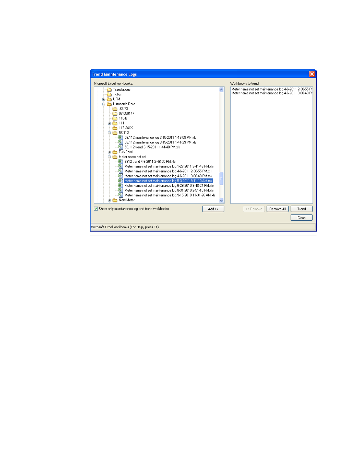
Trend log collectionFigure 1-2:
This is important since many diagnostics change slowly overtime. Trending the
maintenance logs helps identify these changes and makes problems much more obvious
than merely viewing a single inspection report. The Trending feature is integral to Daniel
MeterLink™ which allows all important parameters to be trended. Daniel MeterLink
supports trending files in a Microsoft® Excel ®workbook from multiple 3410 Series meter
maintenance logs. Some parameters like gain, signal level,and noise level may show a shift
over time which can be useful in detecting changes in the meter and the installation.
Maintenance logs or Trend files to be trended must all have matching column headings.
This means the logs must be in the same units (i.e. U.S. Customary or Metric), must have
the same pressure type (i.e. gage or absolute), and must have the same time base (1/
second, 1/minute, 1/hour, 1/day). If not, an error message will be displayed stating the
column headings do not match and the file will not be added to the Workbook to trend
list.
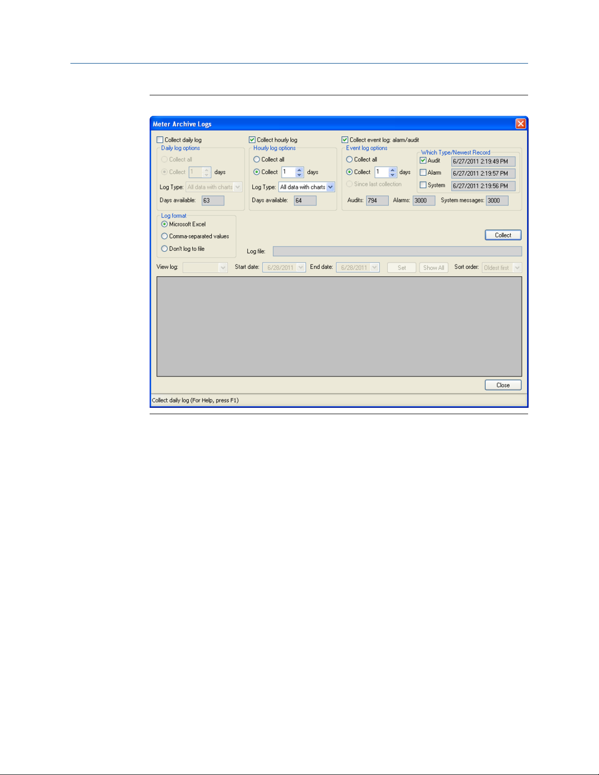
Archive log collection
Archive logs may be collected and the options include:
• Daily log - generated every 24 hours on the Contract Hour
• Hourly log - generated every hour at the top of the hour
• Event log - collects the alarm and event log records
Maintenance and Troubleshooting manual 5
Page 16
Maintenance
Archive log collection parametersFigure 1-3:
The logs may be collected in a single file or you can choose to collect one type of log. Each
of the Meter Archive logs include the Meter Configuration file.
6 Gas Ultrasonic Flow Meter
Page 17
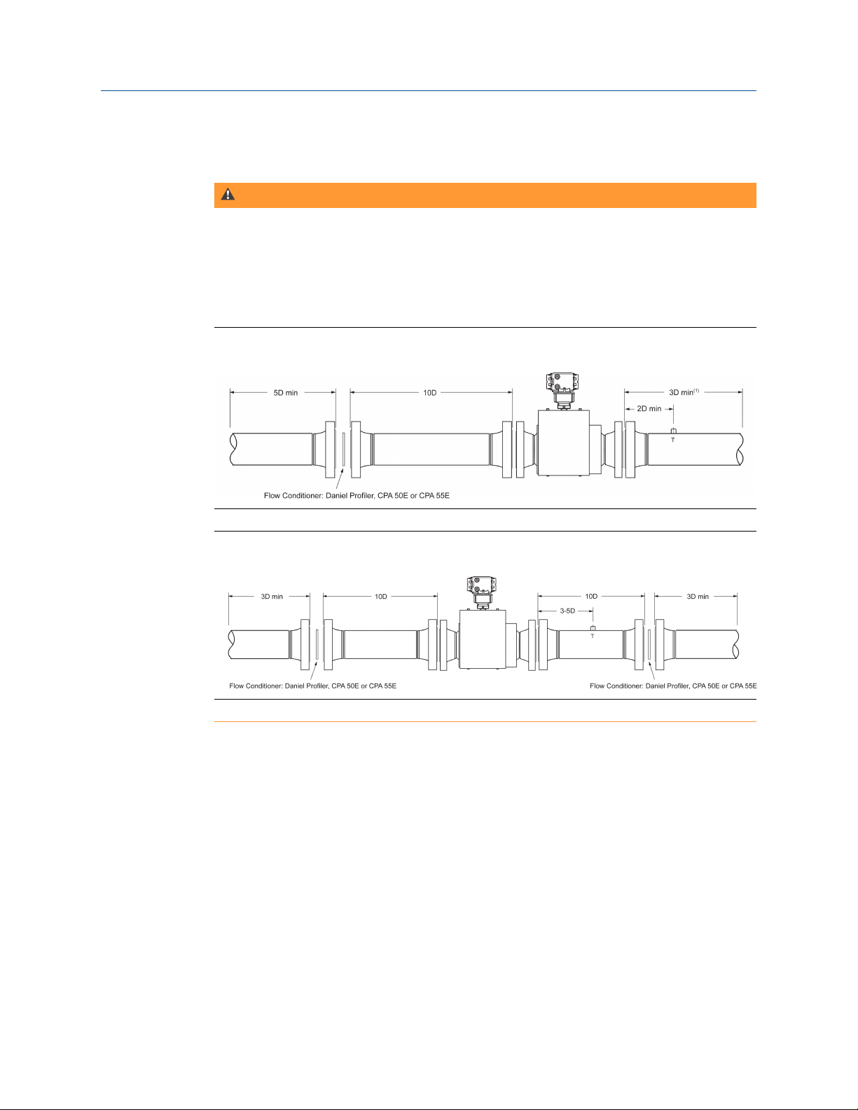
1.3.2 Pipeline cleaning maintenance
WARNING!
BURST HAZARD
Before pipeline cleaning and maintenance ("pigging operations"), remove straightening vanes
or flow conditioners.
Failure to comply may cause excessive pressure in the meter system, resulting in death, serious
injury or equipment damage.
Maintenance
Figure 1-4:
Figure 1-5:
Straightening vanes or flow profilers must be removed during pipeline cleaning
maintenance operations (“pigging operation”). If the meter run is pigged with a flow
conditioner in line, pressure may build up and cause the pipes and flanges to burst and
severely injure personnel. The excessive pressure may damage the meter or the transducer
ports may collect debris which may impede data acquisition and flow measurement.
3410 Series Gas Ultrasonic Flow Meter with flow conditioner for unidirectional flow
3410 Series Gas Ultrasonic Flow Meter with flow conditioner for bidirectional flow
1.3.3 Visual inspection
Periodically inspect meter and meter run for signs of components loosening or seals
leaking. This includes:
Procedure
1. Fluids leaking from seals. This could be visually noticed for liquids leaking. It may be
audible for gasses leaking. Ice may also form at a point of a gas leak.
Maintenance and Troubleshooting manual 7
Page 18

Maintenance
2. Movement of components that should be rigid.
3. Excessive noise due to vibration could be sign of a loose component.
Inspection should be more frequent in systems with a large amount of vibration.
8 Gas Ultrasonic Flow Meter
Page 19
2 Troubleshooting
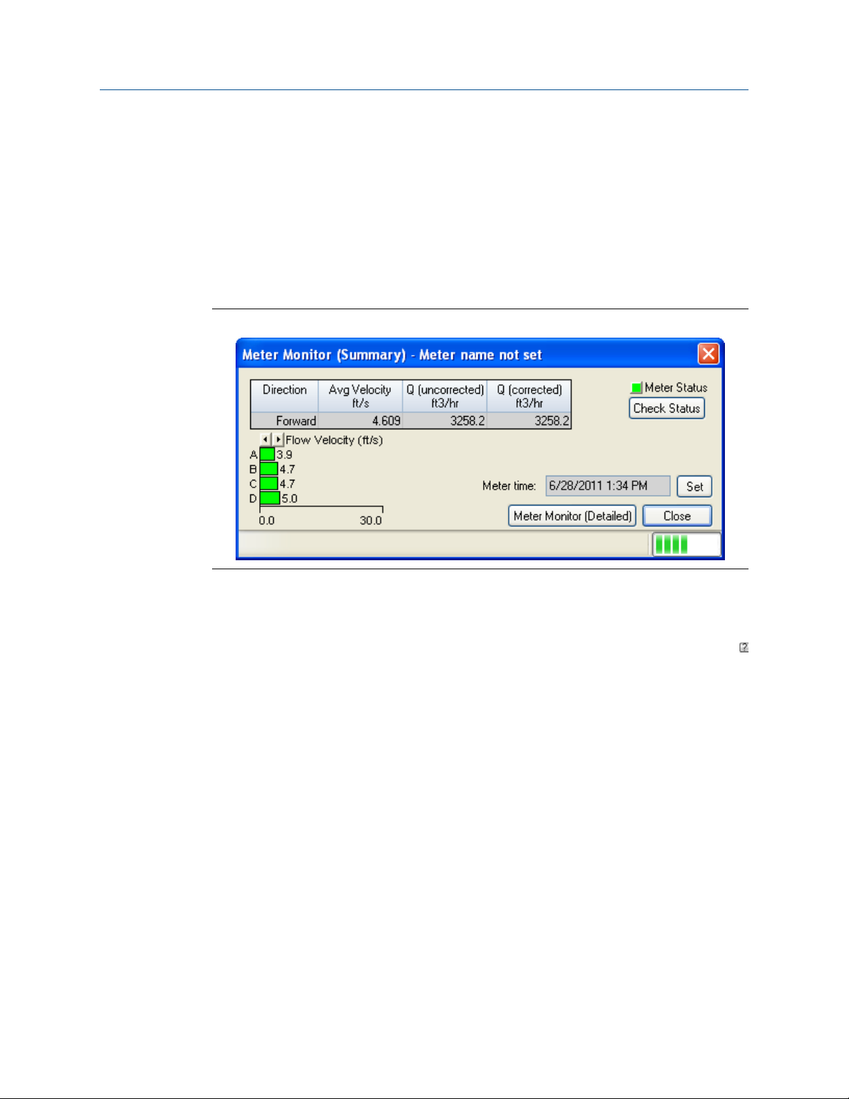
2.1 Meter status alarms
Run Daniel MeterLink™ and open the Meter Monitor (Summary) view to perform a
diagnostics health check.
Meter Monitor status alarmsFigure 2-1:
Troubleshooting
If the meter is measuring flow and operating within the calibration parameters the Meter
Status LED is green. If the Meter Status LED is red, an active alarm exists that requires you
to take corrective action. Click the Check Status button to display the Status Summary
screen. The alarms are shown with the primary causes listed first. Click the question mark
next to the alarm to display a help topic related to the alarm and recommended actions to
resolve the issue.
Maintenance and Troubleshooting manual 9
Page 20
Troubleshooting
Status summaryFigure 2-2:
2.1.1 Check status
Click the Check Status button if any of the LEDs are yellow or red to see more specific
information causing the status alarm. Some alarms do not require an acknowledge and will
clear automatically when the alarm condition goes away. Alarms that require a user to
acknowledge them will have a button to the right titled ACK. Clicking the ACK button
changes the button text to Wait and sends a request to the meter to clear the alarm. The
alarm will disappear from the Check Status dialog once the alarm actually clears.
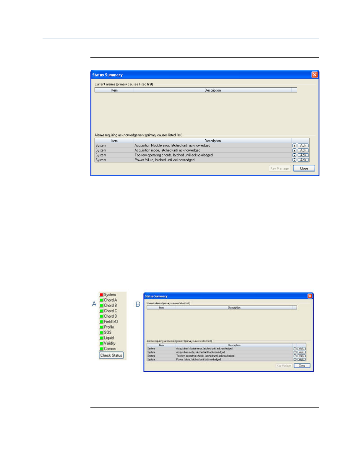
Click the Check Status button and Daniel MeterLink™ opens the Status Summary dialog box
that gives a short description of all alarms present.
Status SummaryFigure 2-3:
A. Active alarm conditions from Meter Monitor page
B. Status summary page with alarm examples
Following is a list and a brief description of the types of alarms:
10 Gas Ultrasonic Flow Meter
Page 21
• System
• Power Loss
• Field I/O
• Validity
• Comms
• Check Status
2.1.2 System alarm
The System alarm indicates a failure in the hardware that should be addressed by a service
technician. This includes memory checksum errors and communication errors within the
hardware. A Red LED indicates a System alarm condition. Collect a Maintenance log and an
audit/alarm log and then, contact your Daniel service representative. This could be an
alarm condition that occurred and remains latched until the condition is resolved and the
alarm is cleared by clicking the ACK button on the Monitor | Check Status| Status Summary page.
2.1.3 Chord A, Chord B, Chord C and Chord D alarm
Troubleshooting
Chord A, Chord B, Chord C, and Chord D - These alarms indicate how a chord is
functioning.
LED colorsTable 2-1:
LED Color Problem
Green No alarms are present. Chord is operating properly.
Yellow At least one sample in the batch caused an alarm but it didnotcausethechordto-
fail.Thesamplewillnotbeusedinthebatch.Discardingoccasional samples can occur
during normal operation such as during flow velocity changes.
Red The chord has failed or is in acquisition. This chord is not used for this batch. Chords
that have failed or are shown to be in acquisition for repeated batches indicates that
the meter should be inspected by a service technician.
Gray The chord has manually been set to inactive.
2.1.4 Field I/O alarm
Reports various field I/O devices that are in alarm. Click the Check Status button for more
details on specific alarms. The field is grayed out if the Daniel 3410 Series Ultrasonic Gas
Flow Meter does not support this alarm.
2.1.5 Validity alarm
This alarm indicates that the meter may not be measuring accurately. Click Check Status to
see a description of which validity alarms are active. The validity alarms QMeter and QFlow
indicate an issue with the meter collecting enough information from the chords to make
Maintenance and Troubleshooting manual 11
Page 22

Troubleshooting
an accurate measurement. The validity alarms for pressure and temperature indicate that
the value is above or below the alarm limits for these values. Red and green are the only
colors used for this alarm.
2.1.6 Comms alarm
The Comms alarm indicates that communications between Daniel MeterLink and the
meter failed. This could be due to a poor communication link. Daniel MeterLink continues
to retry communications. Red and green are the only colors used for this alarm.
2.1.7 Communications
The Communications Analyzer (via Daniel MeterLink Tools> Menu>Communications Analyzer
menu path) displays communications between Daniel MeterLink and the ultrasonic meter.
This utility is useful for troubleshooting communications to the meter. It displays many of
the TCP/IP commands between Daniel MeterLink and the connected meter.
For troubleshooting communications with the 475 Field Communicator for the HART
Protocol, refer to Section 5 of the Emerson 475 Field Communicator User’s Manual, Rev D.
This manual may be downloaded from the following location:
®
http://www2.emersonprocess.com/en-US/brands/Field-Communicator/Pages/
Support.aspx
For troubleshooting communications with AMS Device Manager, refer to the help
documentation and support at the following web site:
http://www2.emersonprocess.com/en-US/brands/amssuite/amsdevicemanager/Pages/
AMSDeviceManager.aspx
12 Gas Ultrasonic Flow Meter
Page 23

3 Meter repairs
Topics covered in this chapter:
• Precautions
• T-Slot transducer removal and installation
• Transducer holder removal and installation
• Transducer cable removal and installation
• Replace the meter electronics
• Acquisition Module replacement
3.1 Precautions
This section includes discussion of the maintenance of Daniel 3410 Series Ultrasonic
Meters.
Meter repairs
For reference, you may download the Daniel MeterLink Quick Start Manual from:
http://www2.emersonprocess.com/en-US/brands/daniel/Flow/ultrasonics/Pages/
MeterLink.aspx
CAUTION!
SURFACE TEMPERATURE HAZARD
The meter body and piping may be extremely hot or cold.
Wear appropriate personal protective equipment when coming in contact with the meter.
Failure to comply may result in injury.
CAUTION!
TRANSPORTATION HAZARD
When moving the meter, do not insert the forks of a forklift into the bore.
Inserting the forks may cause the meter to become unstable, resulting in injury or damage to
the bore and sealing face.
CAUTION!
TRIPPING HAZARD
Clear all obstacles or obstructions from the work area when transporting, installing or
removing the meter.
Failure to clear the work area may cause injury to personnel.
Maintenance and Troubleshooting manual 13
Page 24

Meter repairs
NOTICE
Prior to lifting the unit, refer to the Daniel 3415, 3416, or 3417 Gas Ultrasonic Flow Meter
nameplate or outline dimensional (general arrangement) drawing for the assembled weight.
WARNING!
FLUID CONTENTS MAY BE UNDER PRESSURE
When the meter is under pressure, DO NOT attempt to remove or adjust the transducer holder.
Attempting to do so may release pressurized gas or fluid, resulting in serious injury or
equipment damage.
WARNING!
CONTENTS MAY BE HAZARDOUS
The meter must be fully depressurized and drained before attempting to remove the
transducer holder. If gas or fluid begins to leak from the transducer holder, stop immediately
and reinstall the holder.
Failure to comply may cause serious injury or equipment damage.
A. Transducer holder
CAUTION!
ESCAPING GASES OR FLUIDS HAZARD
The purchaser of the meter is responsible for the selection of Daniel components/seals and
materials compatible with the chemical properties of gas flow measurement.
Failure to select the suitable meter component/seals may cause escaping gases or liquids,
resulting in injury or equipment damage.
14 Gas Ultrasonic Flow Meter
Page 25

WARNING!
CRUSHING HAZARD
During meter installation or removal, always place the unit on a stable platform or surface that
supports its assembled weight.
Failure to comply could allow the meter to roll, resulting in serious injury or equipment
damage.
For basic maintenance, refer to Section 1.2.
3.2 T-Slot transducer removal and installation
The T-Slot transducer assembly offers improved transducer alignment and superior
acoustic isolation between the transducer and the meter housing. The net result is
improved performance and stability. The assembly is used on Daniel 3417, 3416 and 3415
meters and is line pressure vented. The gas temperature ranges are as show in
Temperature ranges for transducers, mounts and holders.
Meter repairs
Transducer type Temperature range Mount and holder type
1
T-21
2
T-22
1
T-41
1
T-21 and T-41 transducers use W-01 transformers
2
T-22 transducers use W-02 transformers
3.2.1 Transducer removal
-20 °C to +100°C (-4 °F to 212
°F)
-50 °C to +100°C (-58°F to 212
°F)
-50 °C to +100°C (-58°F to 212
°F)
Standard mounts/Holders, NBR
O-ringInconelmounts/
316LHolders, NBR O-ringInconelMounts/InconelHolders/
FKMO-ring
Standard mounts/Holders, NBR
O-ring Inconelmounts/
316LHolders, NBR O-ringInconelMounts/InconelHolders/
FKMO-ring
Standard mounts/Holders, NBR
O-ring Inconelmounts/
316LHolders, NBR O-ringInconelMounts/InconelHolders/
FKMO-ring
1. Blow the line down according to the site standard operating procedures.
2. Ensure that the line pressure is down to atmospheric pressure prior to disassembly.
3. Disconnect transducer cabling from the transducer assembly by removing the
retaining clips and pulling the cable plug straight out. Do not twist or rotate the
plug.
Maintenance and Troubleshooting manual 15
Page 26

Meter repairs
4. Remove the transformer retainer using a 1 1/8” wrench and then disconnect and
remove the transformer module (Figure 3-1).
Note
T-21 transducers use W-01 transformers and T-22 transducers use W-02 transformers.
T-21 and T-22 transducer assemblyFigure 3-1:
A. Transducer cable (max. length 15 ft.)
B. Retainer clips
C. Transformer retainer (Standard P/N 1-360-01-958 or High Temperature P/N
1-360-01-978)
D. Transformer module T-21/T-41 (W-01 P/N 1-360-03-090) or T-22 (W-02 P/N
1-360-03-110)
E. Transducer holder
F. Transducer holder O-rings
G. Set screw holes (end of transducer holder)
H. Transducer assembly
I. Mount and backup O-ring
5. Loosen the T-Slot transducer holder assembly with a 1 1/4” socket. Carefully remove
the T-Slot transducer assembly.
16 Gas Ultrasonic Flow Meter
Page 27

6. Loosen the three Allen setscrews with a 1/16” hex driver securing the transducer
assembly and stalk, if installed. Carefully remove the old transducer by pulling it
from the T-Slot transducer holder assembly without rotating.
Important
Record the “L” dimension of the removed transducers which is used to update the meter
configuration after all of the transducers are replaced. Make sure you have the report sheet
containing the “L” dimension, Delay Time, and Delta Delay Time for the replacement pair of
transducers to use during the Transducer Swap-out procedure in Daniel MeterLink.
7. Clean the transducer holder with a dry cloth.
3.2.2 Install transducers
1. Ensure that the Daniel 3410 Series Ultrasonic Gas Flow Meter transducer port,
mount, and T-Slot transducer holder assembly are clean and free of debris.
2. Apply a small amount of Molykote 111to the female contacts on the transducer.
3. Install the transducer assembly into the transducer holder or into the stalk (if
required). The parts are keyed and can only be assembled one way. As the
transducers are installed into the holder or stalk assembly, they must be labeled
with a marker for future reference (i.e., transducer #1 would be A-1 and transducer
#2 would be A-2).
4. Use a 1/16” hex driver to equally tighten the three Allen set screws on the
transducer holder to secure the transducer assembly and the stalks (if installed).
Meter repairs
Transducer holder, stalk and transducer assemblyFigure 3-2:
A. Transduce holder
B. Stalk
Transducer assembly
Maintenance and Troubleshooting manual 17
Page 28

Meter repairs
Note
Do not apply lubricant to the transducer or stalk O-rings.
NOTICE
Ensure that the transducers identified as belonging to end 1 are installed on end 1 of the
meter housing and those identified as belonging to end 2 are installed on end 2 of the
meter housing.
5. Replace the O-ring and Backup O-ring on the transducer holder. It is highly
recommended that the O-rings be replaced when the transducer is removed from
the holder or stalk. Make sure that the contoured side of the ring is facing away from
the mount. Lubricate with Molykote111 Silicone Grease or equivalent.
6. Apply a small amount of nickel anti-seize (N.A.S.) compound (P/N 2-9-9960-134) to
the outer threads of the transducer holder (see Section 3.2.2).
7. Carefully install the transducer holder assembly into the transducer mount. Make
sure the threads of the holder and mount are correctly aligned. Use a 1 1/4” socket
and screw the transducer assembly into the mount. Tighten to securely seat the
assembly in the mount. Do not over tighten (see Figure 3-3).
8. Install the keyed transformer module into the transducer holder (see Figure 3-3).
a. Apply a small amount of Molykote 111 to the transformer module O-ring.
b. Insert the keyed transformer module into the back end of the transducer holder.
18 Gas Ultrasonic Flow Meter
Page 29

Meter repairs
Figure 3-3:
T-21 and T-22 transducer assembly, holder, transformer assembly,
retainer, retaining clip and transducer cable
A. Mount (Inconel mount and holder)
B. Transducer holder (Type - H1 P/N 1-360-01-128, H2 P/N 1-360-01-228)
C. T-21 transformer module (W-01 P/N 1-360-03-090) or T-22 transformer module (W-02 P/N
1-360-03-110)
D. Transducer port (meter body)
E. Transformer retainer (P/N 1-360-01-160)
F. Retaining clip
G. Transducer cable:
• 100°C - 5’ length P/N 1-360-03-232)
• 100°C -15’ length (P/N 1-360-03-233)
9. Place the retainer over the transformer assembly, ensure the retainer threads are
aligned correctly and hand-tighten. Use a 1 1/8” wrench and turn clockwise until the
transformer retainer is fully seated in the transducer holder.
Note
Do not over tighten the retainer.
10. Reconnect the transducer chordset to retainer. The internal connector of the
transducer chordset is keyed and will only go on one way. Secure the transducer
cable plug by installing retaining clips.
11. Repeat Step 1 through Step 10 for the remaining transducer assemblies which were
replaced.
12. Check that the Daniel 3410 Series Ultrasonic Gas Flow Meter is pressure tight.
Pressurize the meter to line pressure. Check for leaks around all mounts and
transducer holders, which were removed, using soapy water or other recognized
Maintenance and Troubleshooting manual 19
Page 30

Meter repairs
leak detector. If leaks are found, the meter must be vented to atmosphere and the
problem corrected. Check for leaks again. Continue the process until there are no
leaks.
13. Continue with Section 3.2.4 to use the Daniel MeterLink™ Transducer Swap-out
Wizard.
3.2.3 Replace the transformers
The following procedure shows how to replace a transformer module. Refer to Figure 3-1
and Figure 3-3.
Procedure
1. Disconnect the transducer cable from the transducer retainer by removing the
retaining clips and pulling the cable plug straight out. Do not twist or rotate the
plug.
2. Unscrew the transformer retainer from the holder using a 1 1/8” wrench.
3. Pull the transformer module from the transducer holder assembly.
4. Apply a small amount of Molykote 111 to the O-rings on the replacement
transformer module.
5. Plug the replacement transformer module into the transducer holder assembly. The
transformer is keyed and can only be installed one way.
Note
T-21 and T-41 transducers use W-01 transformers and T-22 transducers use W-02
transformers.
6. Place the transformer retainer over the transformer module. Ensure the retainer
threads are aligned correctly and hand-tighten. Use an 1 1/8” wrench and turn
clockwise until fully seated in the transducer holder.
Note
Do not over tighten the retainer.
7. Plug the keyed chordset into the transformer assembly and install retainer clips.
3.2.4 Modifying the calibration parameters
When transducer pairs, mounts, stalks or transducer holders are replaced, the
corresponding meter calibration parameters must be updated for accurate operation. This
means modifying the affected chord "L" dimension (LA... LD) (see Determining the “L”
Value below), average delay time (AvgDlyA... AvgDlyD) and delta delay time (DltDlyA...
DltDlyD) using the Daniel MeterLink Transducer Swap-out Wizard (see Figure 3-4).
20 Gas Ultrasonic Flow Meter
Page 31

Meter repairs
Average delay time and delta delay time modifications
The transducer pair average delay time and delta delay time are located on the transducer
pair calibration sheet. These values must be downloaded to the appropriate meter data
points (AvgDlyA... AvgDlyD, DltDlyA... DltDlyD). The lengths of the transducers are also
included on the calibration sheet and are etched on the transducers. Likewise the lengths
of the stalk assemblies, transducer holders, and mounts are etched on the individual
components. The length of the meter body is found on the original calibration sheet
supplied with the meter.
Determining the “L” value
The value "L" is determined by adding the length of the meter body to the lengths of the
two mounts and subtracting the lengths of the transducer holders, stalk assemblies, and
transducers. This value should be written to the appropriate meter data points for each
chord that received new transducers (LA... LD). See Chord “L” Dimension Calculation for the
“L” dimension calculation.
Maintenance and Troubleshooting manual 21
Page 32

Meter repairs
Daniel MeterLink Transducer Swap-out WizardFigure 3-4:
22 Gas Ultrasonic Flow Meter
Page 33

Meter repairs
Chord “L” Dimension Calculation
The chord “L” dimension is calculated from the meter housing length as well as the
transducer pair lengths, mount lengths, holder lengths, and stalk lengths as shown in
Equation Chord "L" Dimension. The transducer lengths are etched on the transducers.
Likewise, the lengths of the mounts, stalk assemblies, and transducer holders are also
etched on the individual components. The length of the meter body is found on the
original calibration sheet supplied with the meter.
Maintenance and Troubleshooting manual 23
Page 34

Meter repairs
Chord “L” Dimension Equation 3-1:
L
chord
= L
MeterHousing
− L
Xdcr1
− L
Xdcr2
− L
− L
+ L
Stalk 1
Stalk 2
Mount1
− L
− L
+ L
Hldr1
Hldr2
Mount2
L
chord
L
MeterHousing
L
Mount1
L
Mount2
L
Xdcr1
L
Xdcr2
L
Stalk1
L
Stalk2
L
Hldr1
L
Hldr2
Tip
The transducer “L” dimension is re-calculated when you run the Transducer Swap-out utility.
chord “L” dimension (in) (LA ... LD)
meter housing length (in)
transducer 1 mount length (in)
transducer 2 mount length (in)
transducer 1 length (in)
transducer 2 length (in)
transducer 1 stalk length (in)
transducer 2 stalk length (in)
transducer 1 holder length (in)
transducer 2 holder length (in)
3.3 Transducer holder removal and installation
WARNING!
CONTENTS MAY BE UNDER PRESSURE
When the meter is under pressure, DO NOT attempt to remove or adjust the transducer holder.
Attempting to do so may release pressurized gases, resulting in serious injury or equipment
damage.
WARNING!
CUTTING HAZARD
Sharp edges may be present on the meter.
Wear appropriate personal protective equipment when working on the meter. Failure to
comply may cause serious injury.
3.3.1 Remove the transducer holder
Daniel 3410 Series Ultrasonic Gas Flow Meters utilize transducer holders that contain the
transducer assemblies and act as the pressure barrier between the transducers and the
fluid. Under normal maintenance such as transducer replacement, the transducer holders
do not need to be removed. If it is necessary to remove the transducer holders, the
24 Gas Ultrasonic Flow Meter
Page 35

Meter repairs
following steps detail how to safely remove and reinstall them. Before removing and
installing the transducer holder, connect to the meter using Daniel MeterLink and collect
and save a Maintenance Log.
1. Blow the line down according to the site standard operating procedures.
2. Ensure that the line pressure is down to atmospheric pressure prior to disassembly.
3. Disconnect the transducer cable by removing the retaining clips and pulling the
cable plug straight out. Do not twist or rotate the plug. (See Figure 3-3).
4. Remove the transformer retainer using a 1 1/8” wrench and then disconnect and
remove the transformer module (Figure 3-1).
Note
T-21 and T-41 transducers use W-01 transformers and T-22 transducers use W-02
transformers.
5. Use a 1 1/4” (32 mm) wrench on the hex of the transducer holder and slowly
unscrew in a counterclockwise direction from the meter. If you hear gas leaking
from the threads, immediately stop and reinstall the holder as the meter has not
been fully drained and/or pressure has not been relieved from the meter. Correct
the issue before attempting to remove the holder.
The transducer holder has now been removed from the meter with the transducer
still installed inside the transducer holder.
6. Make a note of the removed transducer holder length which is used to update the
meter configuration during the Transducer Swap-out procedure in Daniel MeterLink,
after all of the transducer holders are replaced.
Maintenance and Troubleshooting manual 25
Page 36

Meter repairs
Transducer holder length and set screw identificationFigure 3-5:
A. Transducer holder set screws
B. Transducer holder length identification
7. Loosen the three Allen setscrews with a 1/16” hex driver securing the transducer
assembly and stalk, if installed. Carefully remove the transducer by pulling it from
the T-Slot transducer holder (or stalk if installed) without rotating.
8. Clean the holder with a dry cloth.
3.3.2 Install the transducer holder
1. Ensure that the Daniel 3410 Series Ultrasonic Gas Flow Meter transducer port,
mount, and T-Slot transducer holder assembly are clean and free of debris.
2. Insert the transducer (parts are keyed and can only be assembled one way) into the
stalk or into the new transducer holder if no stalk is required. Do not use any
lubricant on the O-rings or contacts of the transducers.
NOTICE
Ensure that the transducers identified as belonging to end 1 are installed on end 1 of the
meter housing and those identified as belonging to end 2 are installed on end 2 of the
meter housing.
26 Gas Ultrasonic Flow Meter
Page 37

Transducer holder, stalk and transducer assemblyFigure 3-6:
A. Transducer holder
B. Stalk
C. Transducer assembly
Meter repairs
3. Replace the O-rings and backup rings on the transducer holder. Make sure the
contoured side of the backup ring faces away from the transducer holder. It is highly
recommended that the O-rings be replaced when the transducer is removed from
the holder/stalk.
4. Use a 1/16” hex driver to equally tighten the three Allen set screws on the
transducer holder to secure the transducer assembly and the stalks (if installed).
5. Apply a light coat of Molykote 111
(1)
Silicone grease or equivalent to the transducer
holder O-rings.
6. Ensure that the transducer port, mount, and T-Slot transducer assembly are clean
and free of debris.
7. Apply a small amount of nickel anti-seize compound (P/N 2-9-9960-134) to the
outer threads of the transducer holder.
8. Insert the T-Slot transducer assembly into the meter transducer port. Tighten with
crescent wrench to securely seat the assembly in the mount. Do not over tighten.
9. Plug the transformer module into the transducer holder assembly. The transformer
module is keyed and can only be installed one way.
10. Place the transformer retainer over the transformer module. Ensure the transformer
retainer threads are aligned correctly and hand-tighten. Use an 1 1/8” wrench and
turn clockwise until fully seated in the transducer holder.
11. Align the keyed transducer cable and securely seat into the transducer holder and
secure with retaining clips.
Note
The transducer cable is keyed and will only go on one way.
(1) Molykote 111 is a trademark of Dow Corning Corporation, U.S.A.
Maintenance and Troubleshooting manual 27
Page 38

Meter repairs
12. Repeat Step 1 through Step 11 for all transducer holders to be replaced.
13. Slowly repressurize the meter to line pressure. Check for leaks as the meter is
pressurized. If you hear gas leaking from the threads, recheck all connections and
resolve the problem. Then, slowly repressurize the meter to line pressure.
14. Connect to the meter with Daniel MeterLink and update the transducer parameters.
From the Tools|Transducer Swap-out menu, run the Transducer Swap-out Wizard. This
utility allows you to update the parameters for the components that are replaced.
Note
Running the Transducer Swap-out utility is required when transducers, mounts, holders, or
stalks are replaced for a chord.
a. After writing all of the changes to the meter’s configuration, open the Monitor
(Detailed View) and verity the meter is acquiring data, the transducers have
good signals and flow profiles for the all of the chords displayed.
b. Collect and save a Maintenance Log and verify the meter is optimally performing.
Save the meter configuration file. If communicating with the meter via Modbus
or HART, manually update the parameters (see Section 3.2.4).
3.4 Transducer cable removal and installation
Daniel 3410 Series Ultrasonic Gas Flow Meters have red transducer cables that plug
directly in the back of the transformer retainer.
Note
Make a note of the exiting cabling path layout to allow proper tie-wrap configuration later in this
procedure.
28 Gas Ultrasonic Flow Meter
Page 39

Meter repairs
Daniel 3410 Series Ultrasonic Gas Flow Meter transducer cables and portsFigure 3-7:
A. Cable ties
B. 3410 Series Ultrasonic Meter transducer port
C. Transducer assembly
WARNING!
CRUSHING HAZARD
During meter installation or removal, always place the unit on a stable platform or surface that
supports its assembled weight.
Failure to comply could allow the meter to roll, resulting in serious injury or equipment
damage.
3.4.1 Replace transducer cables
The meter body ports are identified by stamped or cast lettering adjacent to the
transducer port. Transducers for transmitter head 1 will be labeled 1-A1, 1-A2, etc. while
the transducer for transmitter head 2 will be labeled 2-A1, 2-A2, etc.
1. Remove power to the meter.
2. Disconnect the transducer cable from the transformer retainer by removing the
retaining clips and pulling the cable plug straight out. Do not twist or rotate the
plug. (See Figure 3-3.)
Maintenance and Troubleshooting manual 29
Page 40

Meter repairs
3. Cut the tie wraps for the transducer cable you are replacing.
4. Remove the four bolts holding the Base Enclosure cover to the Transmitter
Electronics Enclosure using a 6mm Allen wrench.
5. Lift the Transmitter Electronics Enclosure from the Base Enclosure. It may be
necessary to remove the ground lug wire and loosen the conduit connections prior
to removal.
6. Carefully prop the Transmitter Electronics Enclosure to the side.
7. Use a flat-blade screw driver and disconnect all the plugs from the Acquisition
module. (See Model 34 Ultrasonic Meter Acquisition Module wiring.)
8. Loosen the three screws that mount the Acquisition Module into the base enclosure
and remove the Acquisition module.
9. Loosen the thumb screws and remove the cable covers below the electronics
mounting bracket.
10. Unscrew the transducer cable to be replaced from the Acquisition module plug.
11. To avoid having to remove the electronics mounting bracket, it is recommended to
cut the plug off the end of the old transducer cable and attach the end of the new
transducer cable to it with tape or by wrapping the discrete wires together. The new
transducer cable can them be pulled up and through the electronics mounting
bracket.
12. Disconnect the new transducer cable from the old transducer cable. Finish removing
the old cable by pulling it through the base enclosure gasket. The new cable can
then be pushed through the base enclosure gasket.
13. Make sure the new transducer cable is routed properly and then cut off excess
length. Strip the individual wires 1/4 inch and install wire ferrules. Screw wires into
the Acquisition module plug.
14. Reinstall the Acquisition modules and securely tighten the plugs back to the
module.
15. Place the transmitter head back on the base enclosure and secure it with the four
bolts.
16. Reinstall the cable covers under the electronics bracket and secure by tightening the
thumb screws.
17. Reinstall the shroud covers over the transducers and wire seal if necessary.
18. Reattach the external ground wire to the ground lug and power up the meter.
30 Gas Ultrasonic Flow Meter
Page 41

Meter repairs
Model 3410 Ultrasonic Meter Acquisition Module WiringFigure 3-8:
3.5 Replace the meter electronics
The following procedure should be performed by a qualified service technician or trained
personnel. Observe all warning labels on the meter before starting this procedure.
The Daniel 3410 Series Gas Ultrasonic Flow Meter Transmitter Electronics Enclosure
consists of the following:
• CPU Module assembly (P/N 1-360-03-010)
• Optional I/O Module (RS-232 or RS-485)
• I.S. Barrier Board (P/N 360-03-004)
Maintenance and Troubleshooting manual 31
Page 42

Meter repairs
• Power Supply (P/N 360-03-003)
• Backplane Board (P/N 360-03-007)
The Daniel 3410 Series Gas Ultrasonic Flow Meter Base Enclosure consists of the following:
• Acquisition Module (P/N 1-360-03-008) (T-21, T-22, T-41)
• Transducer Cable (5FT P/N 1-360-03-232, 15FT P/N 1-360-03-233)
Should the Daniel 3410 Series Ultrasonic Gas Flow Meter require disassembly in the field
(i.e., check boards, change switch settings, or replace boards), to prevent electrostatic
damage to the electronic boards, always use a ground strap while handling the circuit
boards. If one is not available, make sure you are electrically discharged before touching
the boards by first touching a metal surface such as a ground lug on the meter or a table.
3410 Series electronicsFigure 3-9:
A. Terminal end of Transmitter Electronics Enclosure
B. Backplane board location
C. End cap security latch
D. Base enclosure with Acquisition Module
3.5.1 Replace CPU module or Optional I/O module
1. Remove power to the meter.
2. Disconnect security seals on the Transmitter Electronics Enclosure (see
Transmitter Electronics Enclosure security seals), loosen the end cap security latches
using a 3 mm Allen wrench (see
Model 3410 Ultrasonic Meter Acquisition Module wiring) and remove end cap from the
terminal end of the Transmitter Electronics Enclosure.
3. Disconnect the CPU Module terminal blocks (or the optional I/O Module terminal
blocks) if replacing the CPU Module (terminal end of the enclosure) or the Optional
I/O Module.
32 Gas Ultrasonic Flow Meter
Page 43

Meter repairs
CPU or I/O Module replacementFigure 3-10:
A. Terminal end of Transmitter Electronics Enclosure
B. CPU Module
C. Optional I/O Module
D. Power Supply board
E. Fuse
F. Internal chassis ground
Maintenance and Troubleshooting manual 33
Page 44

Meter repairs
CPU module Type 2 and Type 4Figure 3-11:
A. CPU Module Type 2 - side label
B. CPU Module Type 4 - side label
4. Grasp the outer ends of the module you want to replace and pull it out of the
enclosure.
5. Insert the new CPU Module or I/O Module into the enclosure and firmly push until
the board is fully seated into the Backplane Board connectors and the lock is
engaged.
6. Replace the terminal blocks for the CPU Module and/or the Optional I/O Module and
verify the tightness of the terminals with a 3 mm flat blade screw driver.
7. If you are not replacing other electronics, replace the end cap and security latches
(requires a 3 mm Allen wrench). If required, install the security seal wire into and
through one of the two holes in the end cap. Choose holes that minimize
counterclockwise through one of the two holes in the end cap. Choose holes that
minimize counterclockwise rotation of the end cap when the security wire is taut
(maximum wire diameter.078 inch; 2.0 mm).
34 Gas Ultrasonic Flow Meter
Page 45

Meter repairs
Transmitter electronic enclosure security sealsFigure 3-12:
A. Transmitter Electronics Enclosure end cap
B. Security wire seals
8. Adjust the security wire, removing all slack and thread into the lead seal.
9. Cut wire ends to remove excess wire.
10. If replacing other electronics or the fuse, continue with Section 3.5.2, Section 3.5.3
and Section 3.6 before replacing the end caps and sealing the enclosure.
11. If you encounter problems replacing the electronics, see the Flow Lifecycle Services
contact information on the back cover of this manual for Daniel products.
12. This completes the CPU Module or I/O Module replacement procedure.
3.5.2 Fuse replacement
1. Remove power to the meter.
2. Disconnect the Transmitter Electronics Enclosure security seals (see
Transmitter Electronics Enclosure security seals), loosen the end cap security latch
(requires a 3 mm Allen wrench) on the terminal end of the enclosure (see Figure 3-9)
and remove the end cap.
3. Use a 1/4 inch standard flat head screw driver and remove the Fuse Holder cap by
rotating cap counter clockwise. (See Figure 3-10.)
4. Insert the replacement fuse (Littlefuse #218002.HXP) into the Fuse Holder.
5. Install the fuse cap into the holder and push until it is flush with the holder.
Maintenance and Troubleshooting manual 35
Page 46

Meter repairs
6. Turn the fuse cap clockwise 1/8 turn using a 1/4 inch standard flat head screw driver.
7. Replace the end cap and security latch (requires a 3 mm Allen wrench). If required,
install the security seal wire into and (requires a 3 mm Allen wrench). If required,
install the security seal wire into and through one of the two holes in the end cap.
Choose holes that minimize counterclockwise rotation of the end cap when the
security wire is taut (maximum wire diameter.078 inch; 2.0mm) (see Figure 3-12).
8. Adjust the security wire, removing all slack and thread into the lead seal.
9. Cut wire ends to remove excess wire.
10. Apply power to the meter.
11. This completes the fuse replacement procedure.
3.5.3 Replace Backplane, I.S. Barrier or Power Supply board
The following sections detail removal of the Backplane board, the I.S. Barrier Board and the
Power Supply Board.
Backplane replacement
1. If replacing the Backplane board, remove power to the meter.
2. Disconnect the Transmitter Electronics Enclosure security seals, loosen the end cap
security latches (3mm Allen wrench required) and remove both end caps (see
Figure 3-12).
3. Remove the CPU Module and the Optional I/O Module (if installed). See Figure 3-10
for board locations and associated terminal blocks.
4. Use a Phillips head screw driver and remove the four Backplane board screws and
captive star washers from the enclosure standoffs.
5. Pull the Backplane board out of the enclosure. This disconnects the I.S. Barrier
Board. Lay the Backplane board down with the Acquisition Cable still attached (the
Power Supply board may remain attached to the Backplane when you remove it
from the enclosure).
36 Gas Ultrasonic Flow Meter
Page 47

Meter repairs
Backplane board replacementFigure 3-13:
A. Non-terminal end of Transmitter Electronics Enclosure
B. Power Supply board
C. I.S. Barrier board (inside the Guide Plate)
D. Acquisition cable
E. Backplane board
6. Use a 3 mm flat head screw driver and disconnect the Acquisition Cable terminal
block from the Backplane. Unplug the Acquisition Cable from the Backplane.
7. Remove the Power Supply (if it was not removed with the Backplane board) and I.S.
Barrier boards from the enclosure. The I.S. Barrier Board has a notched tab that
secures the board to the Guide Plate.
8. Attach the Acquisition Cable terminal block to the new Backplane Board and plug
the Power Supply Board and I.S. Barrier board into the Backplane board.
9. Insert the Backplane (with the Power Supply and I.S. Barrier Boards attached to the
Backplane) into the enclosure.
10. Fully seat the CPU Module and Optional I/O Module onto the Backplane board.
Maintenance and Troubleshooting manual 37
Page 48

Meter repairs
11. Install the four Phillips head screws to secure the Backplane to the enclosure
standoffs.
12. Reinstall the terminal blocks on the CPU Module, Optional I/O Module (if installed),
and the Power Supply board using a 3 mm flat head screw driver.
NOTICE
Make sure the terminal blocks are aligned with the Guide Plate openings.
13. Recheck the connections, wiring and switch settings before replacing the end caps.
14. Continue with the following sections (if replacing other electronics) before replacing
the end caps and sealing the enclosure.
15. Replace the end caps, security latches, reseal the meter and apply power if you are
not replacing other electronics. If required, install the security seal wire into and
through one of the two holes in the end cap. Choose holes that minimize
counterclockwise rotation of the end cap when the security wire is taut (maximum
wire diameter.078 inch; 2.0 mm) (see Transmitter Electronics Enclosure security seals).
16. Adjust the security wire, removing all slack and thread into the lead seal.
17. Cut wire ends to remove excess wire.
18. Apply power to the meter.
This completes the Backplane Board replacement procedure.
If you encounter problems with this procedure, see the Flow Lifecycle Services for
Daniel products contact information on the back cover of this manual.
I.S. Barrier Board replacement
1. If replacing the I.S. Barrier board, remove power to the meter.
2. Disconnect the Transmitter Electronics Enclosure security seals, loosen the end cap
security latches with a 3mm Allen wrench and remove both end caps (see
Transmitter Electronics Enclosure security seals).
3. Use a 3 mm flat head screw driver and remove the terminal blocks from the Power
Supply board, the CPU Module and the Optional I/O Module (if installed). See
Figure 3-10 for board locations and associated terminal blocks.
4. Use a Phillips head screw driver and remove the four Backplane board screws from
the enclosure standoffs. If the Local Display Module is installed on the Backplane,
use a flat blade screw driver and remove the four flat-head screws from the
standoffs.
5. Pull the Backplane board out of the enclosure. This disconnects the I.S. Barrier
Board. Lay the Backplane board down with the Acquisition Cable still attached (the
Power Supply board may remain attached to the Backplane when you remove it
from the enclosure).
38 Gas Ultrasonic Flow Meter
Page 49

Meter repairs
I.S. Barrier board replacementFigure 3-14:
A. Non-terminal end of Transmitter Electronics Enclosure
B. Power Supply board
C. I.S. Barrier board (inside the Guide Plate)
D. Acquisition cable
E. Backplane board
6. Remove the I.S. Barrier Board from the Guide Plate on the right side of the
enclosure.
7. Install the new I.S. Barrier board onto the Backplane Board and seat the Power
Supply board onto the Backplane board.
8. Insert the Backplane, I.S. Barrier board and the Power Supply Board into the
enclosure.
9. Fully seat the CPU Module and Optional I/O Module onto the Backplane Board.
10. Attach the Backplane to the enclosure standoffs with the four Phillips head screws. If
the Local Display Module is installed on the Backplane, use a flat blade screw driver
and install the four flat-head screws into the enclosure standoffs.
Maintenance and Troubleshooting manual 39
Page 50

Meter repairs
11. Reinstall the J7 terminal block, if removed, on the Backplane board. Re-install the
CPU Module, Optional I/O Module (if installed) and the Power Supply.
12. Module, Optional I/O Module (if installed) and the Power Supply.
13. If replacing other electronics, continue with the following procedures before
replacing the end caps and sealing the enclosure.
14. If you are not replacing other electronics, replace the end caps and security latches
(3 mm Allen wrench required). If required, install the security seal wire into and
through one of the two holes in the end cap. Choose holes that minimize
counterclockwise rotation of the end cap when the security wire is taut (maximum
wire diameter.078 inch; 2.0 mm).
Transmitter electronics enclosure security sealsFigure 3-15:
A. Transmitter Electronics Enclosure end cap
B. Security wire seals
15. Adjust the security wire, removing all slack and thread into the lead seal.
16. Cut wire ends to remove excess wire.
17. Apply power to the meter.
18. This completes the I.S. Barrier Board replacement procedure.
19. If you encounter problems with this procedure, see Flow Lifecycle Services for Daniel
products contact information on the back cover of this manual.
40 Gas Ultrasonic Flow Meter
Page 51

Meter repairs
Power Supply Board replacement
1. If replacing the Power Supply board remove power to the meter.
2. Disconnect the Transmitter Electronics Enclosure security seals, loosen the end cap
security latches with a 3mm Allen wrench and remove both end caps (see
Figure 3-15).
3. Use a flat head screw driver and remove the terminal blocks from the Power Supply
board, the CPU Module and the Optional I/O Module (if installed). See Figure 3-10 for
board locations and associated terminal blocks.
4. Use a Phillips head screw driver and remove the four Backplane board screws from
the enclosure standoffs. If the Local Display Module is installed on the Backplane,
use a flat blade screw driver and install the four flat-head screws into the enclosure
standoffs.
Maintenance and Troubleshooting manual 41
Page 52

Meter repairs
Power Supply board replacementFigure 3-16:
A. Non-terminal end of Transmitter Electronics Enclosure
B. Power Supply board
C. I.S. Barrier board (inside the Guide Plate)
D. Acquisition cable
E. Backplane board
5. Pull the Backplane board out of the enclosure. This disconnects the I.S. Barrier
Board. Lay the Backplane board down with the Acquisition Cable still attached (the
Power Supply board may remain attached to the Backplane when you remove it
from the enclosure).
6. Plug the new Power Supply board and the I.S. Barrier Board onto the Backplane
Board.
7. Insert the Backplane, I.S. Barrier board and the Power Supply Board into the
enclosure and fully seat the CPU Module and Optional I/O Module.
42 Gas Ultrasonic Flow Meter
Page 53

Meter repairs
8. Attach the Backplane to the enclosure standoffs with the four Phillips head screws. If
the Local Display Module is installed on the Backplane, use a flat blade screw driver
and install the four flat-head screws into the enclosure standoffs.
9. Use a flat blade screw driver and install the terminal blocks on the CPU Module,
Optional I/O Module, I.S. Barrier Board and the Power Supply.
10. Recheck the connections, wiring and switch settings before replacing the end caps.
11. If replacing other electronics, continue with Section 3.6 before replacing the end
caps and sealing the enclosure.
12. If you are not replacing other electronics, replace the Transmitter Electronics
Enclosure end caps, install the end cap security latches (3 mm Allen wrench
required). If required, install the security seal wire into and through one of the two
holes in the end cap. Choose holes that minimize counterclockwise rotation of the
end cap when the security wire is taut (maximum wire diameter.078 inch; 2.0 mm)
(see Figure 3-15).
13. Apply power to the meter.
14. This completes the Power Supply Board replacement procedure.
15. If you encounter problems with this procedure, see the Flow Lifecycle Services for
Daniel products contact information on the back cover of this manual.
3.6 Acquisition Module replacement
WARNING!
CRUSHING HAZARD
During meter installation or removal, always place the unit on a stable platform or surface that
supports its assembled weight.
Failure to comply could allow the meter to roll, resulting in serious injury or equipment
damage.
Procedure
1. Remove power to the meter.
2. If the installation has rigid conduit, use a medium size crescent wrench and loosen
the hex nuts on the Transmitter Electronics Enclosure. This should allow enough
slack to remove the Transmitter Electronics Enclosure from the Base Enclosure. If
the installation uses flexible conduit, you may not need to disconnect it from the
Transmitter Electronics Enclosure.
Maintenance and Troubleshooting manual 43
Page 54

Meter repairs
Conduit removalFigure 3-17:
A. Transmitter electronics enclosure
B. Conduit nuts
3. If the meter is equipped with security seals, remove the seals from the bolts on the
Base
44 Gas Ultrasonic Flow Meter
Page 55

Meter repairs
Figure 3-18:
Transmitter Electronics Enclosure and Base Enclosure security seal
removal
A. Transmitter electronics enclosure
B. Base enclosure bolts and security seals
4. Use a 6 mm Allen wrench and remove the four hex head bolts securing the
Transmitter Electronics Enclosure to the Base Enclosure.
Maintenance and Troubleshooting manual 45
Page 56

Meter repairs
Transmitter Electronics Enclosure removalFigure 3-19:
A. Transmitter electronics enclosure
B. Base enclosure bolts
C. Base enclosure
5. Use a 3 mm flat head screw driver and disconnect the Acquisition cable terminal
block and the transducer wire terminal blocks from the Acquisition Module inside of
the Base enclosure.
46 Gas Ultrasonic Flow Meter
Page 57

Meter repairs
Acquisition Module cable and transducer wiringFigure 3-20:
A. Acquisition cable
B. Acquisition wiring terminal blocks
C. Acquisition Module
NOTICE
Make sure the transducer cables are labeled for the chord configuration.
Maintenance and Troubleshooting manual 47
Page 58

Meter repairs
6. Remove the three Acquisition Module flat head screws and split lock washers, then
remove the Acquisition Module from the Base Enclosure.
7. Insert the new Acquisition Module into the Base Enclosure and secure with the three
split lock washers and flat head screws.
8. Reattach the terminal blocks onto the Acquisition Module (3 mm flat head screw
driver required). Make sure the transducer wires have good contact with the
terminal block and the terminal block screws are tight.
9. When you have completed attaching the Transducer wire terminal blocks and the
Acquisition cable terminal block to the Acquisition Module, check the Base
Enclosure o-ring and reinstall if necessary.
10. Reattach the Transmitter Electronics Enclosure to the Base Enclosure with the four
hex head bolts and lock washers. Tighten bolts with a 6 mm Allen wrench.
11. Retighten or reattach the conduit to the Transmitter Electronics Enclosure using a
crescent wrench or channel lock pliers.
12. If required, install security wire seal into and through the hole in the socket head
screw on the Base Enclosure cover (maximum wire diameter 0.078 inch; 2.0mm).
Base Enclosure wire seal installationFigure 3-21:
A. Base Enclosure cover
B. Security wire seals (optional)
13. Position the wire to prevent counterclockwise rotation of the screws when the seal
wire is taut.
48 Gas Ultrasonic Flow Meter
Page 59

Meter repairs
14. Feed the security wire beneath the Transmitter Electronics Enclosure and through
the adjacent socket head screw. Twist the wire, removing all slack and seal.
Base Enclosure security sealsFigure 3-22:
A. Transmitter Electronics Enclosure
B. Transmitter Electronics endcap security latch
C. Security wire seals (optional)
D. Base Enclosure
15. Cut wire ends to remove excess wire.
16. Apply conduit sealing compound according to manufacturer’s recommendations.
17. Apply power to the meter.
18. This completes the Acquisition Module replacement procedure.
Maintenance and Troubleshooting manual 49
Page 60

Meter repairs
50 Gas Ultrasonic Flow Meter
Page 61

Conversion factors
Appendix A
Conversion factors
Topics covered in this appendix:
• Conversion factors per units of measurement
• K-Factor and inverse K-Factor conversions
A.1 Conversion factors per units of measurement
The following table includes conversion factors for many of the Metric and U.S. Customary
units of measure used with Daniel 3410 Series Ultrasonic Gas Flow Meters and Daniel
MeterLink.
Conversion factors per units of measurementTable A-1:
Conversion factors Unit of measurement
(°F-32)x(5/9) -> °C (°C+273.15) - >K
1 K/°C
5/9 °C/°F
10 -6 MPa/Pa
0.006894757 MPa/psi
0.1 MPa/bar
0.101325 MPa/atm
0.000133322 MPa/mmHg
0.3048 m/ft
0.0254 m/in
10 3 dm 3 /m 3
10 -6 m 3 /cc (=m 3 /cm 3 )
(0.3048) 3 m 3 /ft 3
(0.0254) 3 m 3 /in 3
3600 s/h
86400 s/day
10 3 g/kg
0.45359237 kg/lbm
231 in 3 /gal
42 gal/bbl (barrel)
0.0037854 gal/m 3
Maintenance and Troubleshooting manual 51
Page 62

Conversion factors
Conversion factors per units of measurement (continued)Table A-1:
Conversion factors Unit of measurement
6.289811 bbl/m 3
10 -3 Pa•s/cPoise
1.488 Pa•s/(lb/(ft•s))
A.2 K-Factor and inverse K-Factor conversions
Frequency volumetric flow rate K-Factor Equation A-1:
FreqQ
FullScale
(*)
and
KFactor =
(
MaxFreq)3600s § h r
where
KFactor
InvKFactor
FreqQ
FullScale
MaxFreq
(*) TimeUnit
(**) Volume
Frequency volumetric flow rate inverse K-Factor Equation A-2:
InvKFactor =
(
frequency “K-Factor” (pulses/volume**) (Freq1KFactor andFreq2KFactor)
frequency “Inverse K-Factor” (volume**/pulse) (Freq1InvKFactor and
Freq2InvKFactor)
frequency full-scale volumetric flow rate (volume**/time unit*)
(Freq1FullScaleVolFlowRate and Freq2FullScaleVolFlowRate)
maximum frequency (Hz = pulses/time unit*) (Freq1MaxFrequency and
Freq2MaxFrequency)
time conversion factor depends on the VolFlowRate Time Unit data point:
• volume/second = 1 s/s
• volume/minute = 60 s/m
• volume/hour = 3600 s/h
• volume/day = 86400 s/d
where the volume is selected via data points:
• Units System
• VolUnitUS
- gallons
- barrels
MaxFreq
FreqQ
)
(
3600s § hr
FullScale
(*)
)
52 Gas Ultrasonic Flow Meter
Page 63

• VolUnitMetric
- cubic meters
- liters
Conversion factors
Maintenance and Troubleshooting manual 53
Page 64

Conversion factors
54 Gas Ultrasonic Flow Meter
Page 65

Engineering drawings
Appendix B
Engineering drawings
B.1 Daniel 3410 Series Ultrasonic Flow Meter
Drawings
This appendix contains the following engineering drawing(s) for the ultrasonic meter:
DMC-005324 Daniel 3410 Series Gas Ultrasonic Flow Meter System Wiring Diagram
Maintenance and Troubleshooting manual 55
Page 66

Engineering drawings
56 Gas Ultrasonic Flow Meter
Page 67

Page 68

Page 69

Page 70

Page 71

Engineering drawings
Maintenance and Troubleshooting manual 57
Page 72

P/N 3-9000-791
Rev B
2016
Emerson Process Management
Daniel Measurement and Control, Inc.
North America / Latin America:
Headquarters
USA - Houston, Texas
T +1.713.467.6000
USA Toll Free 1.888.FLOW.001
www.EmersonProcess.com/Daniel
Europe: Stirling, Scotland, UK
T +44.1786.433400
Middle East, Africa: Dubai, UAE
T +971.4.811.8100
Asia Pacific: Singapore
T +65.6777.8211
©
2016 Daniel Measurement and Control, Inc. All rights reserved.
Unauthorized duplication in whole or part is prohibited. Printed in
the USA.
Daniel Measurement and Control, Inc. ("Daniel") is an Emerson
Process Management business unit. The Daniel name and logo are
trademarks of Daniel Industries, Inc. The Emerson logo is a
trademark and service mark of Emerson Electric Co. All other
trademarks are the property of their respective companies.
 Loading...