

Page 1

User manual
P/N 3-9008-801, Rev A
December 2017
Daniel ™ Series 1500/1200 Liquid Turbine Meter
Internal Display
Page 2

Flow Lifecycle Services for Daniel products
Location Telephone number Fax number
North America/Latin America +1.713.467.6000 +1.713.827.4805
Flow Lifecycle Services for Daniel products +1.713.827.6314 +1.713.827.6312
USA (toll free) +1.888.356.9001 +1.713.827.3380
Asia Pacific (Republic of Singapore) +65.6777.8211 +65.6777.0947.0743
Europe (Stirling Scotland, UK) +44 (0)1786.433400 +44 (0)1786.433401
Middle East Africa (Dubai, UAE) +971 4 8118100 +971 4 8865465
Daniel Measurement and Control, Inc. (Headquarters)
11100 Brittmoore Park Drive
Houston, TX 77041 USA
http://www.emerson.com/en-us
Email
• Customer Service: Daniel.SystemSales@Emerson.com
• Customer Support: Daniel.SystemSales@Emerson.com
• Asia-Pacific: danielap.support@emerson.com
• Europe: danielEMA.cst@emerson.com
Return Material Authorization (RMA)
A Return Material Authorization (RMA) number must be obtained prior to returning any equipment for any reason. Download the
RMA form from the Support Services web page by selecting the link below.
http://www.emerson.com/en-us/automation/daniel
Page 3

Signal words and symbols
Pay special attention to the following signal words, safety alert symbols and statements:
Safety alert symbol
This is a safety alert symbol. It is used to alert you to potential physical injury hazards. Obey all safety messages that follow this symbol
to avoid possible injury or death.
DANGER!
Danger indicates a hazardous situation which, if not avoided, will result in death or serious injury.
WARNING!
Warning indicates a hazardous situation which, if not avoided, could result in death or serious injury.
CAUTION!
Caution indicates a hazardous situation which, if not avoided, could result in minor or moderate injury.
NOTICE
Notice is used to address safety messages or practices not related to personal injury.
Important
Important is a statement the user needs to know and consider.
Tip
Tip provides information or suggestions for improved efficiency or best results.
Note
Note is “general by-the-way” content not essential to the main flow of information.
Page 4

Important safety instructions
Daniel Measurement and Control, Inc. (Daniel) designs, manufactures and tests products to function within specific conditions.
Because these products are sophisticated technical instruments, it is important that the owner and operation personnel must
strictly adhere both to the information printed on the product and to all instructions provided in this manual prior to installation,
operation, and maintenance.
Daniel also urges you to integrate this manual into your training and safety program.
BE SURE ALL PERSONNEL READ AND FOLLOW THE INSTRUCTIONS IN THIS MANUAL AND ALL NOTICES AND PRODUCT WARNINGS.
WARNING!
Failure to follow the installation, operation or maintenance instructions for a Daniel product could lead to serious injury or death
from explosion or exposure to dangerous substances.
To reduce the risk:
• Comply with all information on the product, in this manual, and in any local and national codes that apply to this product.
• Do not allow untrained personnel to work with this product.
• Use Daniel parts and work procedures specified in this manual.
Product owners (Purchasers):
• Use the correct product for the environment and pressures present. See technical data or product specifications for
limitations. If you are unsure, discuss your needs with your Daniel representative.
• Inform and train all personnel in the proper installation, operation, and maintenance of this product.
• To ensure safe and proper performance, only informed and trained personnel should install, operate, repair and maintain
this product.
• Verify that this is the correct instruction manual for your Daniel product. If this is not the correct documentation, contact
Daniel at 1-713-827-6314. You may also download the correct manual from:
http://www.emerson.com/en-us/automation/daniel.
• Save this instruction manual for future reference.
• If you resell or transfer this product, it is your responsibility to forward this instruction manual along with the product to the
new owner or transferee.
• ALWAYS READ AND FOLLOW THE INSTALLATION, OPERATIONS, MAINTENANCE AND TROUBLESHOOTING MANUAL(S) AND
ALL PRODUCT WARNINGS AND INSTRUCTIONS.
• Do not use this equipment for any purpose other than its intended service. This may result in property damage and/or
serious personal injury or death.
Page 5

Product operation (Personnel):
• To prevent personal injury, personnel must follow all instructions of this manual prior to and during operation of the
product.
• Follow all warnings, cautions, and notices marked on, and supplied with, this product.
• Verify that this is the correct instruction manual for your Daniel product. If this is not the correct documentation, contact
Daniel at 1-713-827-6314. You may also download the correct manual from:
http://www.emerson.com/en-us/automation/daniel .
• Read and understand all instructions and operating procedures for this product.
• If you do not understand an instruction, or do not feel comfortable following the instructions, contact your Daniel
representative for clarification or assistance.
• Install this product as specified in the INSTALLATION section of this manual per applicable local and national codes.
• Follow all instructions during the installation, operation, and maintenance of this product.
• Connect the product to the appropriate pressure and electrical sources when and where applicable.
• Ensure that all connections to pressure and electrical sources are secure prior to and during equipment operation.
• Use only replacement parts specified by Daniel. Unauthorized parts and procedures can affect this product's performance,
safety, and invalidate the warranty. “Look-a-like” substitutions may result in deadly fire, explosion, release of toxic
substances or improper operation.
• Save this instruction manual for future reference.
Page 6

Notice
THE CONTENTS OF THIS PUBLICATION ARE PRESENTED FOR INFORMATIONAL PURPOSES ONLY, AND WHILE EVERY EFFORT HAS
BEEN MADE TO ENSURE THEIR ACCURACY, THEY ARE NOT TO BE CONSTRUED AS WARRANTIES OR GUARANTEES, EXPRESSED OR
IMPLIED, REGARDING THE PRODUCTS OR SERVICES DESCRIBED HEREIN OR THEIR USE OR APPLICABILITY. ALL SALES ARE GOVERNED
BY DANIEL'S TERMS AND CONDITIONS, WHICH ARE AVAILABLE UPON REQUEST. WE RESERVE THE RIGHT TO MODIFY OR IMPROVE
THE DESIGNS OR SPECIFICATIONS OF SUCH PRODUCTS AT ANY TIME.
DANIEL DOES NOT ASSUME RESPONSIBILITY FOR THE SELECTION, USE OR MAINTENANCE OF ANY PRODUCT. RESPONSIBILITY FOR
PROPER SELECTION, USE AND MAINTENANCE OF ANY DANIEL PRODUCT REMAINS SOLELY WITH THE PURCHASER AND END-USER.
TO THE BEST OF DANIEL'S KNOWLEDGE THE INFORMATION HEREIN IS COMPLETE AND ACCURATE. DANIEL MAKES NO
WARRANTIES, EXPRESSED OR IMPLIED, INCLUDING THE IMPLIED WARRANTIES OF MERCHANTABILITY AND FITNESS FOR A
PARTICULAR PURPOSE WITH RESPECT TO THIS MANUAL AND, IN NO EVENT, SHALL DANIEL BE LIABLE FOR ANY INCIDENTAL,
PUNITIVE, SPECIAL OR CONSEQUENTIAL DAMAGES INCLUDING, BUT NOT LIMITED TO, LOSS OF PRODUCTION, LOSS OF PROFITS,
LOSS OF REVENUE OR USE AND COSTS INCURRED INCLUDING WITHOUT LIMITATION FOR CAPITAL, FUEL AND POWER, AND CLAIMS
OF THIRD PARTIES.
PRODUCT NAMES USED HEREIN ARE FOR MANUFACTURER OR SUPPLIER IDENTIFICATION ONLY AND MAY BE TRADEMARKS/
REGISTERED TRADEMARKS OF THESE COMPANIES.
Page 7

Warranty and Limitations
1. LIMITED WARRANTY: Subject to the limitations contained in Section 2 herein, Daniel Measurement & Control, Inc. (“Daniel”)
warrants that the licensed firmware embodied in the Goods will execute the programming instructions provided by Daniel, and that
the Goods manufactured by Daniel will be free from defects in materials or workmanship under normal use and care and Services
will be performed by trained personnel using proper equipment and instrumentation for the particular Service provided. The
foregoing warranties will apply until the expiration of the applicable warranty period. Goods are warranted for twelve (12) months
from the date of initial installation or eighteen (18) months from the date of shipment by Daniel, whichever period expires first.
Consumables and Services are warranted for a period of 90 days from the date of shipment or completion of the Services. Products
purchased by Daniel from a third party for resale to Buyer (“Resale Products”) shall carry only the warranty extended by the original
manufacturer. Buyer agrees that Daniel has no liability for Resale Products beyond making a reasonable commercial effort to
arrange for procurement and shipping of the Resale Products. If Buyer discovers any warranty defects and notifies Daniel thereof in
writing during the applicable warranty period, Daniel shall, at its option, correct any errors that are found by Daniel in the firmware
or Services or repair or replace F.O.B. point of manufacture that portion of the Goods or firmware found by Daniel to be defective, or
refund the purchase price of the defective portion of the Goods/Services. All replacements or repairs necessitated by inadequate
maintenance, normal wear and usage, unsuitable power sources or environmental conditions, accident, misuse, improper
installation, modification, repair, use of unauthorized replacement parts, storage or handling, or any other cause not the fault of
Daniel are not covered by this limited warranty, and shall be at Buyer's expense. Daniel shall not be obligated to pay any costs or
charges incurred by Buyer or any other party except as may be agreed upon in writing in advance by Daniel. All costs of dismantling,
reinstallation and freight and the time and expenses of Daniel's personnel and representatives for site travel and diagnosis under
this warranty clause shall be borne by Buyer unless accepted in writing by Daniel. Goods repaired and parts replaced by Daniel
during the warranty period shall be in warranty for the remainder of the original warranty period or ninety (90) days, whichever is
longer. This limited warranty is the only warranty made by Daniel and can be amended only in a writing signed by Daniel. THE
WARRANTIES AND REMEDIES SET FORTH ABOVE ARE EXCLUSIVE. THERE ARE NO REPRESENTATIONS OR WARRANTIES OF ANY
KIND, EXPRESS OR IMPLIED, AS TO MERCHANTABILITY, FITNESS FOR PARTICULAR PURPOSE OR ANY OTHER MATTER WITH RESPECT
TO ANY OF THE GOODS OR SERVICES. Buyer acknowledges and agrees that corrosion or erosion of materials is not covered by this
warranty.
2. LIMITATION OF REMEDY AND LIABILITY: Daniel shall not be liable for damages caused by delay in performance. The remedies of
Buyer set forth in this agreement are exclusive. In no event, regardless of the form of the claim or cause of action (whether based in
contract, infringement, negligence, strict liability, other tort or otherwise), shall Daniel's liability to Buyer and/or its customers
exceed the price to Buyer of the specific goods manufactured or services provided by Daniel giving rise to the claim or cause of
action. Buyer agrees that in no event shall Daniel's liability to Buyer and/or its customers extend to include incidental, consequential
or punitive damages. The term “consequential damages” shall include, but not be limited to, loss of anticipated profits, revenue or
use and costs incurred including without limitation for capital, fuel and power, and claims of Buyer's customers.
Page 8

Page 9

Contents
Contents
Part I Plan
Chapter 1 Introduction ..................................................................................................................3
1.1 Introduction ............................................................................................................................... 3
1.1.1 Model numbers and accessories ...................................................................................3
1.2 General settings ..........................................................................................................................4
1.3 Rate input settings ..................................................................................................................... 6
1.4 Rate/
1.5 4-20 mA transmitter output settings .......................................................................................... 8
1.6 Open collector output settings ................................................................................................... 9
1.7 Serial communication settings ..................................................................................................10
1.8 Default settings for startup of Internal Display .......................................................................... 10
Chapter 2 Product certifications .................................................................................................. 13
2.1 Agency certifications ................................................................................................................13
2.2 Government installation regulations .........................................................................................13
Display settings ................................................................................................................ 7
Chapter 3 Product connections ................................................................................................... 15
3.1 Connection configuration .........................................................................................................15
3.2 Input signal connections .......................................................................................................... 16
3.3 DC power connection ............................................................................................................... 18
3.4 External reset connection ......................................................................................................... 19
3.5 4-20 mA transmitter output connections ..................................................................................19
3.6 RS-485 serial connections ......................................................................................................... 20
3.7 Open collector output connections ...........................................................................................20
Part II Install
Chapter 4 Installation requirements and limitations ....................................................................25
4.1 Requirements and limitations for installation ............................................................................25
Part III Operate
Chapter 5 Setup and programming ............................................................................................. 29
5.1 Function keys and display .........................................................................................................29
5.2 Button tips ................................................................................................................................31
5.3 Set numeric values ....................................................................................................................32
5.4 Set alphanumeric labels (LAbEL) ............................................................................................... 32
5.5 Main menu ...............................................................................................................................33
5.6 Menu display functions ............................................................................................................ 34
5.7 Set up the meter .......................................................................................................................36
5.7.1 Select input type (InPut) .............................................................................................37
5.7.2 Enter the K-Factor (FActr) ........................................................................................... 39
5.7.3 Display units (UnitS) ................................................................................................... 40
5.7.4 Set the decimal point (dEc.Pt) .................................................................................... 48
User manual i
Page 10

Contents
5.7.5 Configure the display (dSPLY) .....................................................................................48
5.7.6 Custom tag (tAG) ....................................................................................................... 50
5.7.7 Set the toggle time (TIME) ..........................................................................................51
Chapter 6 Product advanced features ..........................................................................................53
6.1 Advanced features menu .......................................................................................................... 53
6.2 Advanced features menu and display messages ........................................................................54
6.3 Open collector outputs (OUTPUT) ............................................................................................ 59
6.3.1 Output 1 and 2 Setup (OUT 1, OUT 2) .........................................................................59
6.4 Scaling the 4-20 mA analog output (Aout) ................................................................................ 63
6.5 Gate function (GATE) ................................................................................................................ 64
6.6 Contact debounce filter (FILTER) ...............................................................................................65
6.7 Low-flow cutoff (CUTOFF) .........................................................................................................65
6.8 Scaling and calibration (SCALCAL) .............................................................................................65
6.8.1 Undo K-Factor, scale, and calibration (Undo?) ............................................................ 66
6.8.2 Scale the meter (SCALE) ............................................................................................. 66
6.8.3 Calibrate the meter (CAL) ........................................................................................... 68
6.8.4 Multi-point linearization (noPtS) ................................................................................ 71
6.9 Total reset (T RESEt) ..................................................................................................................71
6.9.1 Manual or automatic total reset function (t rSt) ..........................................................71
6.9.2 Manual or automatic grand total reset function (GrtrSt) .............................................72
6.10 Set up passwords (PASSWRD) ...................................................................................................73
6.10.1 Lock meter setup parameters .....................................................................................74
6.10.2 Reset total and grand total on a password protected meter ....................................... 74
6.10.3 Disable password protection ...................................................................................... 74
6.10.4 Non-resettable grand total ......................................................................................... 75
6.11 Custom (CUSTOM) ................................................................................................................... 76
6.12 System (SySTEM) ...................................................................................................................... 78
6.12.1 Set real time clock (SETTIME) ..................................................................................... 79
6.12.2 View data log (LOGVIEW) ........................................................................................... 81
6.12.3 Backlight (BAKLITE) .................................................................................................... 81
6.12.4 Analog output calibration (AO CAL) ............................................................................81
6.12.5 Backup and restore (BACkUP) .....................................................................................82
6.12.6 Battery power symbol alert (BAT SyM) ........................................................................83
6.12.7 Information (INFO) ..................................................................................................... 83
6.13 Serial communications (COMM) ............................................................................................... 83
6.14 Standby mode (STANDBy) ........................................................................................................ 84
6.14.1 Wakeup the meter (WAKEUP?) .................................................................................. 85
Chapter 7 Startup procedure ....................................................................................................... 87
7.1 Operation and startup procedure .............................................................................................87
7.2 Button tips ................................................................................................................................89
7.3 Grand total reading (Gr TOTAL) .................................................................................................89
7.4 Max/Min readings (MAXIMUM, MINIMUM) ................................................................................89
7.5 Reset the total (rESEt TOTAL?) .................................................................................................. 90
7.6 Reset the grand total (rESEt Gr TOT?) ........................................................................................90
7.7 Reset Max/Min readings (RESET MAXIMUM, MINIMUM) ............................................................90
7.8 Reset meter to factory defaults .................................................................................................91
7.9 Factory defaults and user settings .............................................................................................91
Part IV Maintain
ii LTM Internal Display
Page 11

Contents
Chapter 8 Maintenance .............................................................................................................. 97
8.1 Troubleshooting tips .................................................................................................................97
8.2 Quick user interface reference .................................................................................................. 98
8.3 Battery replacement ................................................................................................................. 99
User manual iii
Page 12

Contents
iv LTM Internal Display
Page 13

Part I
Plan
Chapters covered in this part:
Introduction
•
Product certifications
•
Product connections
•
Plan
User manual 1
Page 14

Plan
2 LTM Internal Display
Page 15

1 Introduction
Topics covered in this chapter:
• Introduction
• General settings
• Rate input settings
• Rate/Internal Display settings
• 4-20 mA transmitter output settings
• Open collector output settings
• Serial communication settings
• Default settings for startup of Internal Display
Introduction
1.1
1.1.1
Introduction
The Daniel Digital Rate Internal Display is an explosion-proof pulse input rate/display fully
featured for demanding applications in hazardous areas or in the harshest environmental
conditions. It can be programmed using the four through-glass buttons, without
removing the cover, or with four internal push-buttons.
The numeric rate display reads up to five digits and the alphanumeric total/tag display
reads up to 7 digits. The total overflow feature reads up to 12 digits. The alphanumeric
display can also be programmed to display any combination of numbers and letters up to
seven characters long for use as engineering units and/or the process identification tag.
The backlight increases the visibility of the display under various lighting conditions. The
enclosure contains threaded conduit holes and integrated pipe or wall mounting slotted
flanges.
Model numbers and accessories
These are the models and accessories that Daniel offers.
Daniel Part number Description
899-10-230-32
899-10-230-30 4-20 mA powered with battery backup. Loop-Pow-
24 VDC powered with battery backup. Isolated
Mod-Bus Protocol enabled. Loop-Powered
Backlight. Iso-lated 4-20 mA output. 2 pulse
outputs.
ered Backlight. Non-isolated 4-20 mA output. 2
pulse outputs.
User manual 3
Page 16
Introduction
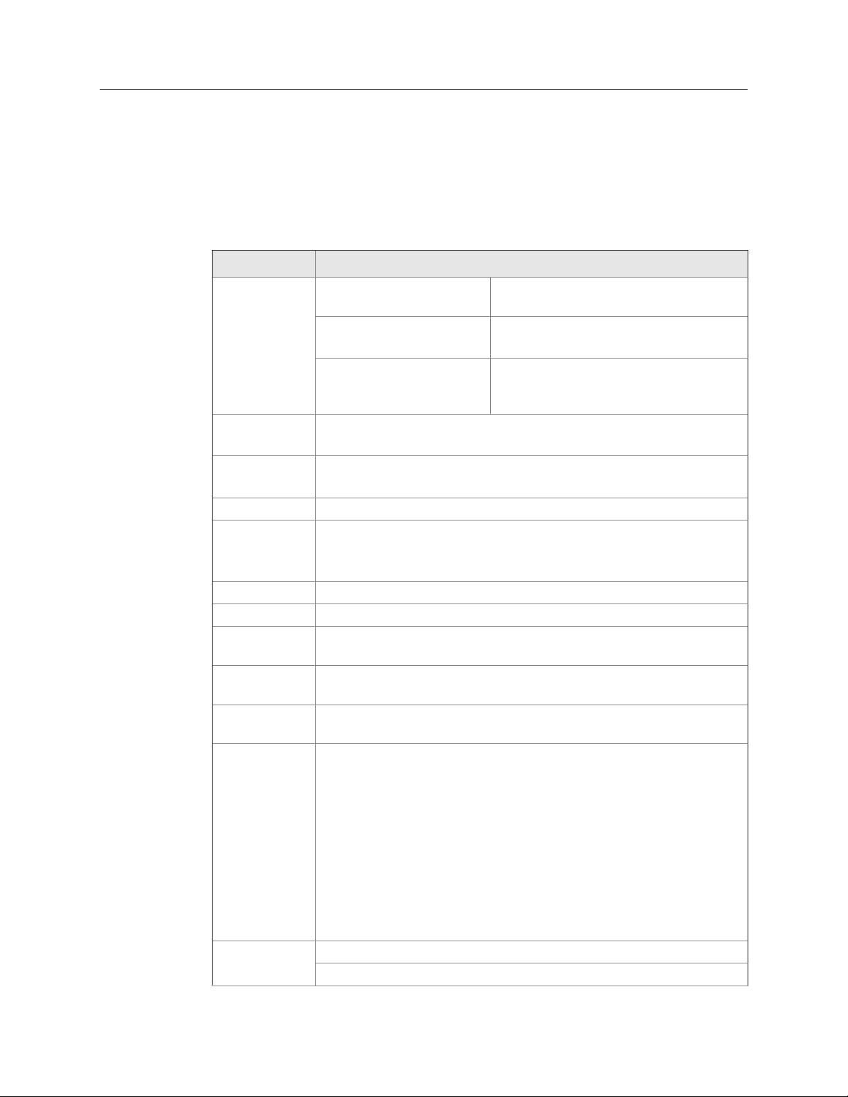
1.2 General settings
The settings below are general specifications for the Internal Display. Except when noted,
all specifications apply to operate at +25°C.
General settings Table 1-1:
Setting Description
Display Five digits Top display (0 to
99999)
Seven characters
Bottom display
Symbols Total, grand total, battery power/low battery,
Display Assignment
Backlight White LED, 10 second auto-off when battery powered
Alarm indication Flashing display plus HI/LO indicators
Display update
rate
Overrange Display flashes 99999
Underrange Display flashes -9999
Programming
methods
Recalibration All ranges are calibrated at the factory to read frequency in Hz. No recalibration
Max/Min display Max/Min readings acquired are stored until reset by the user or until power to
Password menu
options
Power options 9-30 VDC, 2.2 W max
Top display: rate or total
Bottom display: Combinations of rate, total, grand total, units and custom tag
Backlight deactivated below temperatures ≈ -20° C
Ambient > -25°C: 2 Update/Second
Ambient < -25°C: 1 Update/10 Seconds
Note: Update is dependent on gate settings.
Four through-glass buttons when cover is installed. Four internal pushbuttons
when cover is removed.
required.
the meter is cycled.
Three programmable password selections can restrict modification of programmed settings, prevent resetting the total or grand total without the password, or permanently lock out the ability to change or reset the grand total or
any grand total related settings, making a non-resettable grand total.
Pass: Restricts modifications of programmed settings without re-entering the
password.
Pass T: Restricts the reset of total without re-entering the password. Disables
the manual mode reset contact.
Pass GT: Restricts the reset of grand total without re-entering the password.
Enables a non-resettable total and permanent lockout of grand-total related
settings with a specific password.
4-20 mA Transmitter Output Power, 30 VDC max
17.8 mm (0.7") high, 7-segment, automatic
lead zero blanking.
10.2 mm (0.4")high, 14-segment, automatic
lead zero blanking.
high alarm, low alarm, button sleep mode/disable, password lock
4 LTM Internal Display
Page 17

Introduction
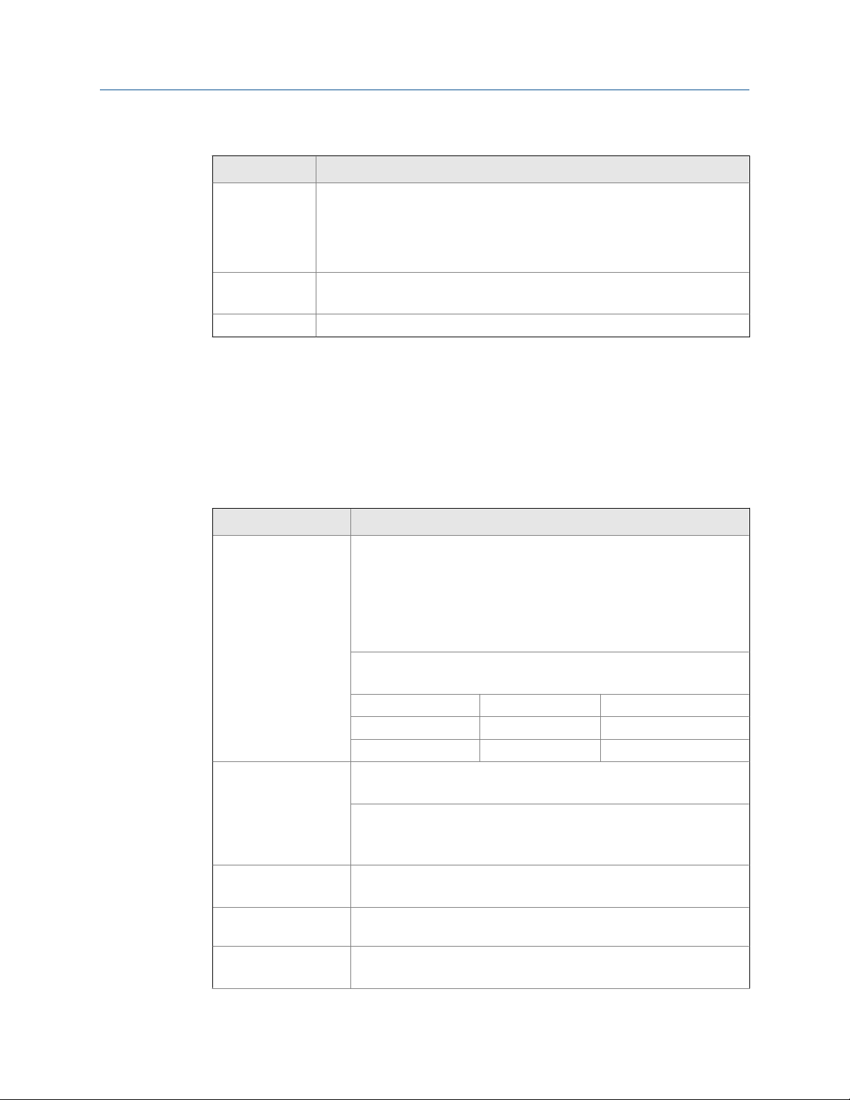
General settings (continued)Table 1-1:
Setting Description
Battery Power
DC Power with battery backup
4-20 mA Output Power with battery backup
Battery 3.6 V Primary Lithium (Li-SOCl2), non-rechargeable model 899-10-230-31
Expected Service Life and Recommended Replacement Interval
Operating Condition Estimated Service Life Suggested Replace-
ment Interval
Open collector outputs off,
through-glass buttons off,
minimal backlight use
<100 kHz open collector outputs, minimal through-glass
button or backlight use
<2 kHz open collector outputs,
minimal through-glass button
or backlight use
<5 kHz open collector outputs,
minimal through-glass button
or backlight use
Backup power only N/A 10 years
Data logging Up to 512 records, recorded four/day at specific times or at defined time inter-
vals. Record contains date, time, rate, total, grand total, and log number.
Isolation All Models 500 V opto-isolated input-to-power/output
899-10-230-30 500 V input-to-output
899-10-230-32 500 V input/power-to-output
Environmental Operating temperature range: -40° C to 75°C
Storage temperature range: -40° C to 75°C
Backlight deactivated below temperatures ≈ -20° C
Relative humidity: 0 to 90% non-condensing
Non-volatile
memory
Connections Screw terminals accept 12 to 22 AWG wire
Enclosure Explosion-proof die-cast aluminum with glass window, corrosion resistant ep-
All programmed settings and total readings are stored in non-volatile memory
for a minimum of ten years if power is lost.
oxy coating, color: blue. NEMA 4X, 7, & 9, IP68. Copper-free (0.3%).
Default conduit connections: Three
NPT metal plug with 12 mm hex key fitting installed. Additional conduit opening configurations and plugs may be available; verify quantity and sizes on specific device labeling during installation.
7.5 years 5.5 years
5.5 years 4 years
2.5 year 2 years
1.3 year 1 year
with isolated input enabled
Note: Requires separate output supply
¾" NPT threaded conduit openings. One ¾"
User manual 5
Page 18
Introduction
General settings (continued)Table 1-1:
Setting Description
display may be mounted directly to conduit by using slotted flanges for
Mounting
The
wall mounting or NPS 1½" to 2½" or DN 40 to 65 mm pipe mounting. Note:
Certain sequences of events can cause unexpected results. To avoid unexpected issues, use factory defaults and anticipate the possibility of changes in the
mounting strategy.
Overall dimensions
Weight 5.00 lbs (80 oz, 2.27 kg)
(144 mm x 133 mm x 124 mm)
5.67" x 5.24" x 4.88" (W x H x D)
1.3 Rate input settings
The settings below are rate input specifications for the Internal Display. Except when
noted, all specifications apply to operation at +25°C (+77°F).
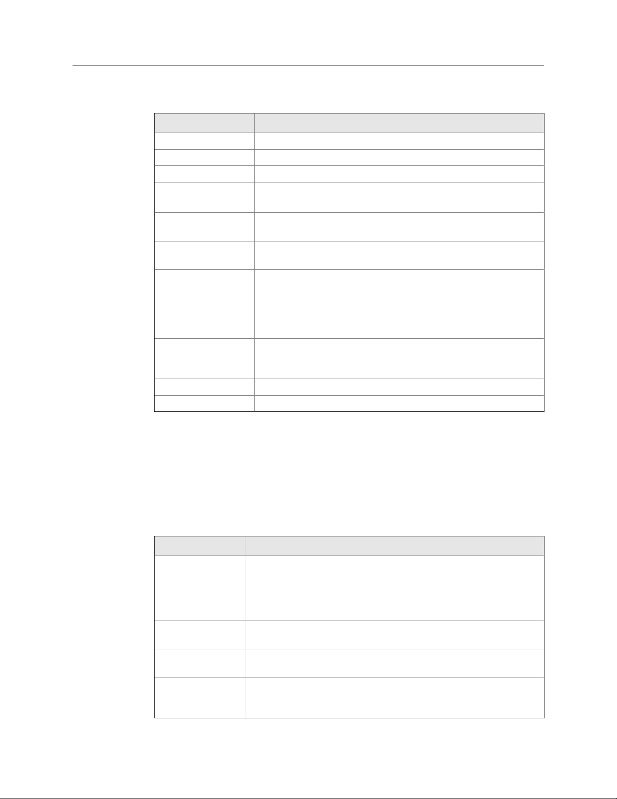
Rate input settingsTable 1-2:
Setting Description
Pulse/ transistor/ contact closure input
Opto-isolated input Sourcing pulse or square wave 0-5 V, 0-12 V, or 0-24 V
Low voltage mag pickup input
Minimum input frequency
Input impedance Pulse input: Greater than 75 kΩ @ 1 kHz.
Field selectable; Sourcing or sinking pulse or square wave 0-5 V, 0-12 V,
or 0-24 V; TTL; NPN or PNP transistor
Open collector 100 kΩ pull-up to 3 V
Switch contact 100 kΩ pull-up to 3 V
PNP transistor 100 kΩ pull-down to ground (COM)
Active input 100 kΩ to battery level, 10 kΩ to power
Maximum Frequency: 64 kHz
Minimum Pulse Width: 5 μs
Threshold Setting Low (V) High (V)
Normal 1.2 1.8
Low 0.2 1.0
Logic High: 2-24 V, Logic Low: < 1 V
Maximum Frequency: 20 kHz
Minimum Pulse Width: 20 μs
Input Current: 1 mA @ 5 V, 2.5 mA @ 12 V, 5 mA @ 24 V
Sensitivity: 20 mVp-p to 24 Vp-p
Maximum Frequency: 6 kHz
0.001 Hz. Minimum frequency is dependent on high gate setting (rate
display).
Open collector/switch input: 100 kΩ pull-up to 3 V.
6 LTM Internal Display
Page 19
Introduction
Rate input settings (continued)Table 1-2:
Setting Description
Accuracy ±0.03% of calibrated span ±1 count
Temperature drift Rate display is not affected by changes in temperature.
Low-flow cutoff 0-99,999 (0 disables cutoff function)
Decimal point Up to four decimal places or none:
4.4444, 33.333, 222.22, 1111.1, or 00000
Calibration May be calibrated using K-Factor, scale without signal source, or by ap-
plying an external calibration signal.
K-Factor Field programmable K-Factor converts input pulses to rate in engineer-
ing units. May be programmed from 0.000001 to 9,999,999 pulses/unit.
Calibration range Input 1 signal must be ≥ 1 Hz; input 2 signal may be set anywhere above
input 1 setting.
Minimum input span is 1 Hz.
An Error message will appear if the input 1 and input 2 signals are too
close together.
Input contact debounce filter
Time base Second, minute, hour, or day
Gate Low gate: 1-99 seconds; High gate: 2-9,999 seconds
Programmable contact debounce filter. Input signal frequency speed selections of Hi (no filter), Med (250 Hz max input, 2 ms pulse width), and
Low (100 Hz max input, 5 ms minimum pulse width).
1.4 Rate/Internal Display settings
The settings below are rate/display specifications for the Internal Display. Except when
noted, all specifications apply to operation at +25°C (+77°F).
Table 1-3: Rate/Internal display settings
Setting Display
Display assignment The Top display calculates rate or total. The Bottom displays total; total and
units; total and tag; total, total units, and rate units; grand total; grand total and grand total units; grand total and tag; grand total, grand total units,
and rate units; rate units; rate; rate and total units; rate and rate units; rate
and tag; rate units; total units; a custom tag; or be off (blank).
Rate display units Gallons, liters, imperial gallons, cubic meters, barrels, bushels, cubic yards,
cubic feet, cubic inches, liquid barrels, beer barrels, hectoliters, or custom.
Rate display time
base
Total and grand total
display units
Display rate may be calculated in terms of units per second, minute, hour,
or day.
Gallons, liters, imperial gallons, cubic meters, barrels, bushels, cubic yards,
cubic feet, cubic inches, liquid barrels, beer barrels, hectoliters, or custom.
Setting is independent for each.
User manual 7
Page 20

Introduction
Table 1-3: Rate/Internal display settings (continued)
Setting Display
Total and grand total
display unit multiplier
Total and grand total
decimal point
Totalizers Calculates total and grand total based on rate and field programmable mul-
Totalizer reset Via through-glass RESET button, manual button (cover off), external con-
Total overflow and
rollover
Grand total overflow
and rollover
External total reset External reset connections are made between RST and COM. Logic High:
x1, x100 (h), x1000 (k), or x1,000,000 (M) multiplier (and prefix) applied to
total or grand total display units. Setting is independent for each.
Up to six decimal places or none:
6.666666, 55.55555, 444.4444, 3333.333, 22222.22, 111111.1 or
0000000
Total and grand total decimal points are independently programmed, and
are independent of rate decimal point.
tiplier to display total in engineering units. Time base must be selected according to the time units in which the rate is displayed. The total and grand
total utilize the same time base, with different conversion factors and resets.
tact closure (total only), automatically via user selectable preset value and
time delay (1 – 99,999 sec). Manual reset may be disabled or protected by
pass word for the total and grand total. Total and grand total reset independently.
The total can display up to 999,999,999,999. Up to 9,999,999 can normally
be displayed on the lower display. A rollover display toggles between the
first 6 digits and last six digits (999,999 <> 999,999) for a 12 digit total. The
total will rollover beyond 999,999,999,999.
The grand total can display up to 999,999,999,999. Up to 9,999,999 can
normally be displayed on the lower display. A rollover display with toggle
between the first 6 digits and last six digits (999,999 <> 999,999) for a 12
digit grand total. The grand total will rollover beyond 999,999,999,999.
1.4V, 3.3V max; Logic Low: < 0.8V.
32 ms debounce.
1.5 4-20 mA transmitter output settings
The settings below are 4-20 mA transmitter output specifications for the Internal Display.
Except when noted all specifications apply to operation at +25°C (+77°F).
4-20 mA transmitter output settingsTable 1-4:
Setting Description
Output source Rate/process, total, grand total or disabled
Scaling range 4.000 to 20.000 mA for any display range
Disable If disabled, the output will output 3.2 mA
8 LTM Internal Display
Page 21
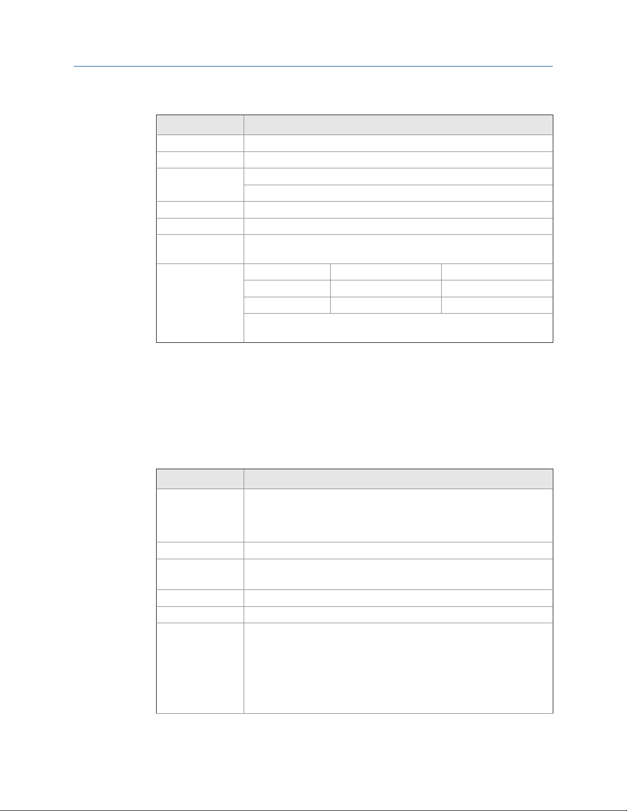
4-20 mA transmitter output settings (continued)Table 1-4:
Setting Description
Calibration Factory calibrated: 0.0 to 1000.0 = 4-20 mA output
Underrange Output underrange: 3.8 mA
Overrange Display overrange: 20.5 mA
Output overrange: 20.5 mA
Accuracy ± 0.05% span ± 0.004 mA
Temperature drift 0.08 μA/°C max from -40°C to 75°C ambient
External loop power
supply
Output loop resistance
30 VDC maximum
Power supply Minimum Maximum
24 VDC 10Ω 700Ω
30 VDC 100Ω 1200Ω
Note: loop-powered backlight subtracts 150Ω from maximum resistance
figures above.
Introduction
1.6 Open collector output settings
The settings below are open collector output specifications for the Internal Display. Except
when noted all specifications apply to operation at +25°C (+77°F).
Open collector output settingsTable 1-5:
Settings Description
Output assignment Two open collector pulse outputs Out 1 and Out 2. Individually programma-
ble for rate, total, or grand total alarms; rate, total, or grand total pulse outputs; or retransmitting of pulse inputs; constant timed pulse output; quadrature outputs (required Out 1 and Out 2); or off.
Rating Isolated open collector, off: 24 VDC max, on: <1 V @ 150 mA max
Alarm output Assign to rate for high or low alarm trip point.
Assign to total or grand total for total or grand total alarms.
Alarm deadband 0-100% FS, user selectable
Alarm acknowledge Front panel ACK button resets output and screen indication.
Pulse output K-Factor (Count)
K-factor (COUNT) programmable from 0.000001 to 9999999. Rate pulses
are generated as a scaled output of the rate input with one output pulse per
K-factor (count) number of input pulses. Total and grand total pulses are
generated for every total or grand total increment selected. (e.g. K-factor
value of 100 generates one pulse every time the total is incremented by 100
units). Rate retransmission pulses one to one for input pulses, up to maximum output speed. K-factor is not used for retransmitting outputs.
User manual 9
Page 22

Introduction
Open collector output settings (continued)Table 1-5:
Settings Description
Pulse output Pulse
width
Pulse output maximum frequency
Quadrature output Output set to quadrature lags the other pulse output by 90° (1/4 duty cycle)
Timer output Programmable on and off time, repeating cycle. Minimum period 0.1 sec-
Unless otherwise stated, pulses are 50% duty cycle for required frequency.
A pulse rate retransmit output generates 100 to 130 μs pulses at the falling
edge of every input pulse.
5 kHz, pulse width at 50% duty cycle.
If the programming of the outputs would exceed 5 kHz, the meter displaysPULSE OVERRNG
at output frequency. Minimum 1 Hz
ond, maximum 100,000 seconds. Minimum pulse time 0.01 second, maximum 10,000 seconds.
1.7 Serial communication settings
The settings below are serial communication specifications for the Internal Display. Except
when noted, all specifications apply to operation at +25°C (+77°F).
Serial communication settingsTable 1-6:
Settings Description
Protocol 2-Wire RS-485 Modbus® RTU
Meter address/slaveID1 - 247
Baud rate 1,200; 4,800; 9,600; 19,200; 38,400; 57,600; or 115,200 bps
Transmit time delay Programmable between 0 and 199 ms
Parity/Stop it Even, odd, none with 1 stop bit, or none with 2 stop bits
Byte-to-byte timeout Max of 1.5 character times or 750 μs
Note: Refer to Modbus Register Tables at www.predig.com for details.
1.8 Default settings for startup of Internal Display
Internal Display factory settings are shown in the table below.
Default settings for startupTable 1-7:
Parameter Display Default setting
Input type INPUT Active
K - Factor units FUN IT Pulses/gallon
10 LTM Internal Display
Page 23

Introduction
Default settings for startup (continued)Table 1-7:
Parameter Display Default setting
K - Factor FACTR 1.0000
Rate time base TBASE Second
Rate unit RATEU Gallons/second
Total unit TOT U Gallons
Total multiplier MULT x1
Grand total unit GTOTU Gal
Grand total multiplier MULT x1
Rate decimal point 1111.1 1 place
Total decimal point 111111.1 1 place
Grand total decimal point 111111.1 1 place
Total conversion factor TOTCF N/A (Only valid with custom
units)
Total reset T RST Manual - Enabled
Grand total conversion factor GRTCF N/A (Only valid with custom
units)
Grand total reset T RST Manual - Enabled
Display DSPLY Total
Advanced features
Output variable A OUT Rate
Output display 1 DSPL 1 0000.0
Output 1 OUT 1 4.000
Output Display 2 DSPL2 1000.0
Output 2 OUT 2 20.000.0
Scale/Cal # Points NOPT5 2
Scale/Cal Input 1 INPT 1 00000
Scale/Cal Display 1 DSPL 1 0000.0
Scale/Cal Input 2 INPT2 1000
Scale/Cal Display 1 DSPL2 1000.0
Parameter Lock Password PASS 00000 (unlocked)
Total Reset Password PASS T 00000 (unlocked)
Grand Total Reset Password PASS GT 00000 (unlocked)
Output 1 OUT 1 Off
Output 2 OUT 2 Off
Low Gate LO GATE 1
High Gate HI GATE 2
Filter FILTER High Speed
User manual 11
Page 24

Introduction
Default settings for startup (continued)Table 1-7:
Parameter Display Default setting
Cutoff CUTOFF 0 (disabled)
Battery Symbol BAT SYM Disabled
Modbus Slave ID SLU ID 247
Baud Rate BAUD 19,200 bps
Time Delay TDELY 10 ms
Parity PARTY Even
12 LTM Internal Display
Page 25

2 Product certifications
Topics covered in this chapter:
Agency certifications
•
Government installation regulations
•
2.1 Agency certifications
The following are product agency certifications applicable to the Internal Display.
Agency certificationsTable 2-1:
Certification type Description
Electrical UL and CUL: Class I, Div. 1, Groups B, C & D
ATEX: Ex d IIC T6 Gb
IECEx: Ex d IIC T6 Gb
INMETRO (Brazil)
Environmental NEMA 4x (IP66)
Product certifications
2.2
Special conditions for safe use
Use a suitably certified and dimensioned cable entry device and/or plug. Install the
equipment so that the supply cable is protected from mechanical damage. Do not subject
the cable to tension or torque. If the cable is to be terminated within an explosive
atmosphere, then appropriate protection of the free end of the cable is necessary.
Year of construction
This information is contained within the serial number with the first four digits
representing the year and month in the YYMM format.
For European community
Install the Internal Display in accordance with the ATEX directive 94/9/EC.
Government installation regulations
Installation in USA
Install the Internal Display in accordance with the National Electrical Code (NEC) NFPA 70.
Installation in Canada
Install the Internal Display in accordance with the Canadian Electrical Code CSA 22.1.
User manual 13
Page 26

Product certifications
Installation in the European Community
Install the Internal Display in accordance with the ATEX directive 94/9/EC.
14 LTM Internal Display
Page 27
3 Product connections
Topics covered in this chapter:
Connection configuration
•
Input signal connections
•
DC power connection
•
External reset connection
•
4-20 mA transmitter output connections
•
RS-485 serial connections
•
Open collector output connections
•
3.1 Connection configuration
The information below describes the configuration for the connector board connections.
Product connections
WARNING!
STATIC ELECTRICITY HAZARD
Static electricity can damage sensitive components. Observe safe handling precautions for
static-sensitive components and use proper grounding procedures/codes.
If the meter is installed in a high voltage environment and a fault or installation error occurs,
high voltage may be present on any lead or terminal resulting in death or serious injury.
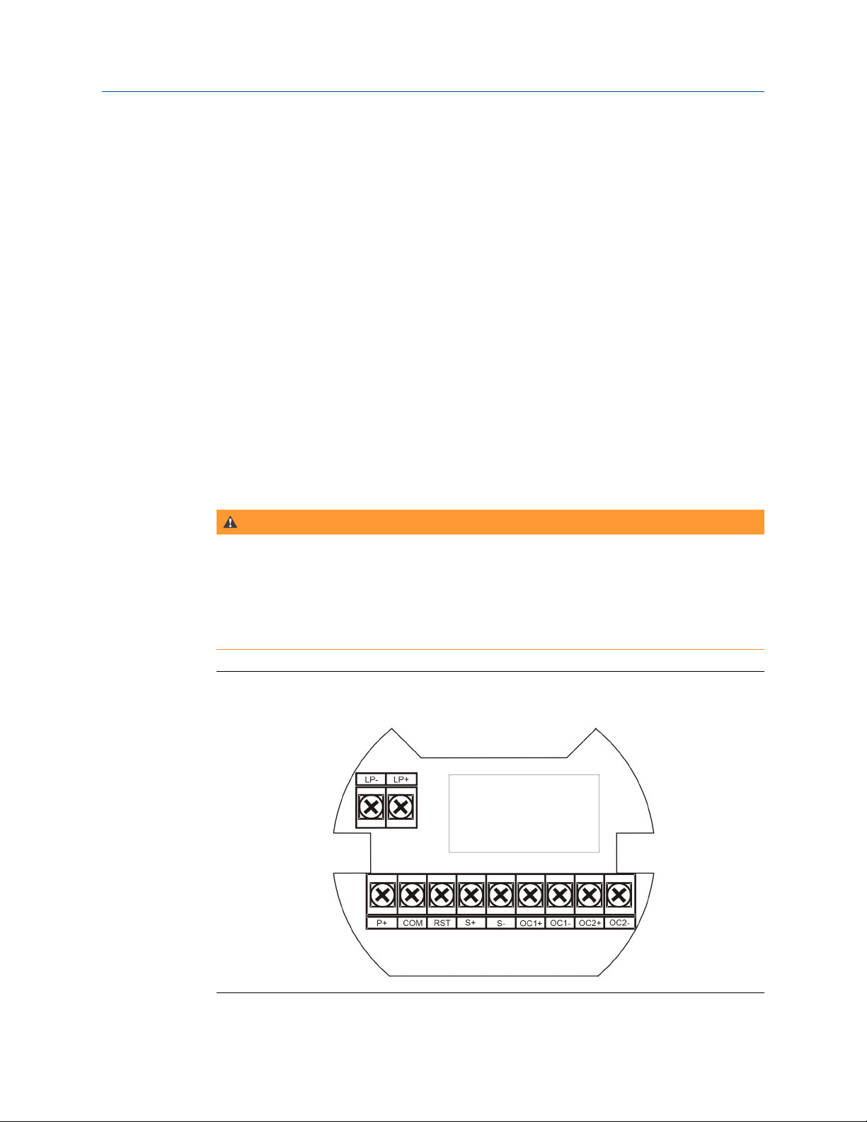
Connector boardFigure 3-1:
User manual 15
Page 28
Product connections
Connector board connections Table 3-1:
Connections Description
S+ Signal input positive terminal connection
S- Signal input negative terminal connection
COM DC power supply input return/negative, reset contact closure common
RST Contact closure reset pull-up to 1.8 VDC
P+ DC Power positive terminal connection
LP+ 4-20 mA transmitter DC power positive terminal connection
LP- 4-20 mA transmitter regulated current output terminal connection
OC1+ Open collector output 1 positive terminal
OC1- Open collector output 1 negative terminal
OC2+ Open collector output 2 positive terminal
OC2- Open collector output 2 negative terminal
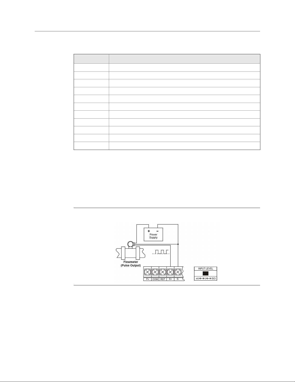
3.2 Input signal connections
Signal connections are made to a barrier terminal mounted in the base of the enclosure.
Input level and type are configured using the slide switches on the bottom of the display
module as shown in the lower right side of the following figures.
Flowmeter powered by external supply (Active)Figure 3-2:
16 LTM Internal Display
Page 29

Product connections
Isolated flowmeter powered by external supply (ISO)Figure 3-3:
Self-powered magnetic pickup coil flowmeter (Coil)Figure 3-4:
NPN open collector input (NPN)Figure 3-5:
User manual 17
Page 30
Product connections
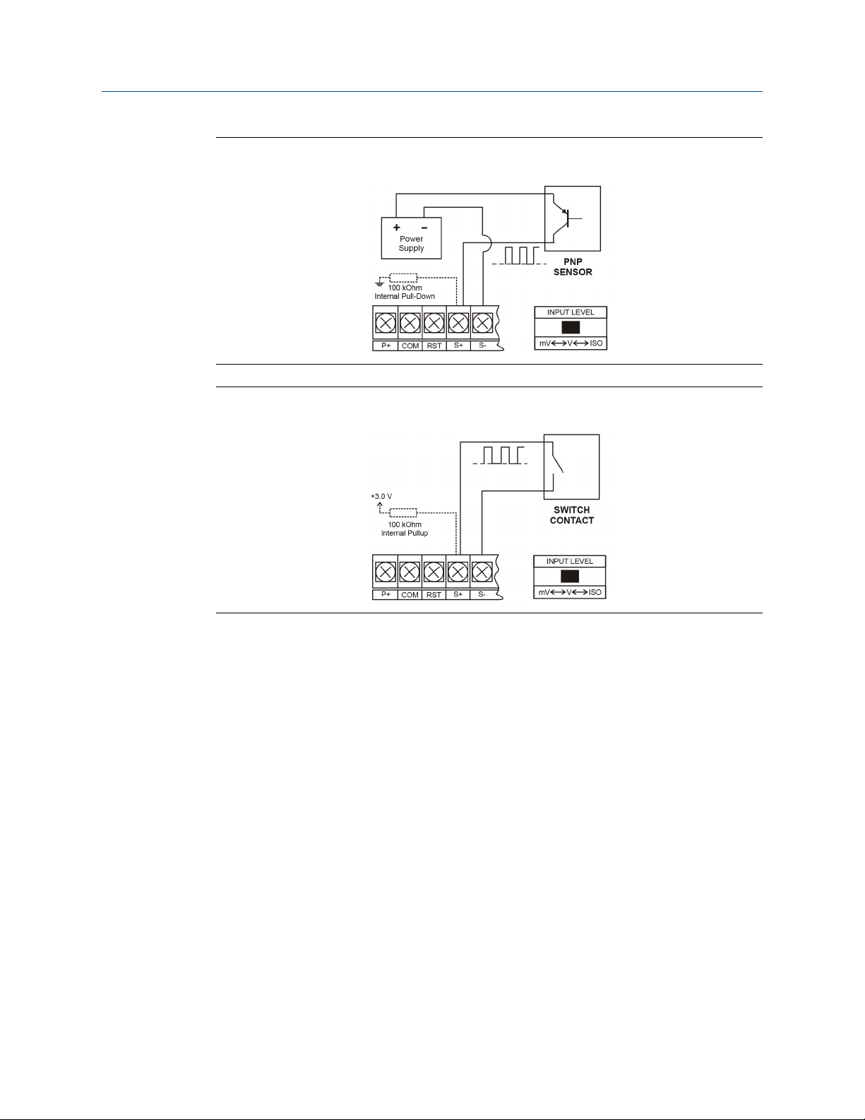
PNP sensor with external power (PNP)Figure 3-6:
Switch contact input (Reed)Figure 3-7:
3.3 DC power connection
Models configured for DC power (899-10-230-32) are provided with a terminal labeled P+
and are wired as shown in Figure 3-9. Models configured for battery power
(899-10-230-30) may optionally be connected to DC power and the battery will function
as backup power when DC is lost. The same power supply may be used to power other
circuits including a PNP-type sensor. However to maintain input isolation, a separate
power supply must be used to power the isolated 4-20 mA transmitter as shown in
Figure 3-10 and/or to power the Opto-Isolated Flowmeter as shown in the figure below.
18 LTM Internal Display
Page 31

DC power connectionsFigure 3-8:
3.4 External reset connection
External reset connections are made between RST and COM. Connect to a contact closure
source such as a relay or a push button as shown in Figure 3-9. Avoid extended contact
closure to preserve battery life. The total is reset when the button is pressed. The meter
starts to totalize immediately. Holding down the button has no effect on the total.
Product connections
Reset connectionsFigure 3-9:
3.5 4-20 mA transmitter output connections
Output connections are made to two terminals labeled LP+ and LP-. Connect to an input
device such as a remote display or chart recorder as shown in the figure below.
User manual 19
Page 32

Product connections
4-20 mA output connectionsFigure 3-10:
3.6 RS-485 serial connections
The meter may include an optional RS-485 two wire serial connection. For an RS-485 serial
communications network should always be a Use high quality cable such as Belden 8162 or
Alpha 6203C. For a two-wire system requires two twisted pairs, and a four-wire system
requires three twisted pairs (the extra twisted pair is needed for the signal ground.
RS-485 two wire serial connectionsFigure 3-11:
S-485 four wire serial connectionsFigure 3-12:
3.7 Open collector output connections
Open collector output 1 and 2 connections are made to terminals labeled OC1+ and OC1-,
and OC2+ and OC2-. Connect the alarm or pulse input device as shown in the figure below.
20 LTM Internal Display
Page 33

Product connections
Open collector output connectionsFigure 3-13:
User manual 21
Page 34

Product connections
22 LTM Internal Display
Page 35

Part II
Install
Install
User manual 23
Page 36

Install
24 LTM Internal Display
Page 37

Installation requirements and limitations
4 Installation requirements and
limitations
4.1 Requirements and limitations for installation
Follow the steps below to access the wiring connectors.
1.
WARNING!
ELECTROCUTION HAZARD
Disconnect from supply before opening enclosure. Keep cover tight while circuits are
alive. Conduit seals must be installed within 450mm (18") of the enclosure.
Failure to follow these instructions may result in death or serious injury.
Open the enclosure to access the wiring connectors. The jam screw on the cover
may need to be loosened. Remove the internal electronic assembly from the
enclosure to access the electrical connectors.
2. Remove the two captive screws. Disconnect the ribbon cable from the display
module and set the display module aside.
3. Disconnect the wires/cables from the electronic board.
4. Install in accordance with applicable local and national regulations (e.g. NEC).
5. Install and service should be performed only by trained service personnel.
6. Service requiring replacement of internal components (not including battery, if
equipped) must be performed at the factory.
7. Use suitably certified and dimensioned cable entry device and/or plug.
8. All input circuits must be derived from a CSA Approved Class 2 source.
User manual 25
Page 38

Installation requirements and limitations
26 LTM Internal Display
Page 39

Part III
Operate
Chapters covered in this part:
•
•
•
Operate
Setup and programming
Product advanced features
Startup procedure
User manual 27
Page 40

Operate
28 LTM Internal Display
Page 41

5 Setup and programming
Topics covered in this chapter:
Function keys and display
•
Button tips
•
Set numeric values
•
Set alphanumeric labels (LAbEL)
•
Main menu
•
Menu display functions
•
Set up the meter
•
5.1 Function keys and display
Setup and programming
Use the infrared through-glass buttons for setup and programming. Use manual buttons
when uncovered. Two slide switches are located on the display module. One is used to
configure the input and the other is used to lock or unlock the infrared through-glass
buttons.
The Display has four infrared through-glass button sensors allowing the Display to be
programmed and operated without removing the cover (and exposing the electronics) in a
hazardous area. These buttons can be disabled for security via the THRU-GLASS BUTTONS
on/off switch on the back of the removable electronics module. Select OFF to disable the
infrared THRU-GLASS buttons.
Button and display symbolsTable 5-1:
Button/Display symbol Description
Menu/Awake
User manual 29
Page 42

Setup and programming
Button and display symbols (continued)Table 5-1:
Button/Display symbol Description
Right arrow/Reset
Up arrow/Display
Enter/Alarm acknowledge
Hi High alarm
Lo Low alarm
Set Total alarm
Settings Lockout Password Enabled
Through-glass power save/disable.
Flashing: Temporarily disabled due to manual button
T Total display
Flashing: Temporarily disabled due to manual button
GT Grand total display
Flashing: Total overflow indication
13 digit total overflow, 6 most significant digits
Bat Flashing: Low battery indicator
Steady: Powered by battery backup
30 LTM Internal Display
Page 43

Setup and programming
Button operationTable 5-2:
Button Procedure
Menu •
Right/Reset • Press the Right arrow button to move to the next digit or decimal position
Up/Display • Press Display when in Run mode to display the grand total, again to dis-
Enter • Press the Enter button to access a menu or to accept a setting.
Hold the Menu button when in Power Save Mode ( will display) to
awaken through-glass buttons.
• Press the Menu button to enter Programming Mode.
• Press the Menu button during Programming Mode to return to the previ-
ous menu selections.
• Hold the Menu button for 1.5 seconds at any time to exit Programming
Mode and return to Run Mode.
• Press and hold the Menu button for 3 seconds to access the Advanced fea-
tures of the meter.
• Press Menu while displaying grand total, max, or min reading to return to
Run mode.
during programming.
• Press Right to go backward through most selection menus.
• Press Right to reset the total, or values displayed in the bottom display
(grand total, max, or min).
• Press Enter after Right to confirm the reset.
play the maximum, and again to display the minimum reading since last
reset. These displays will time out in 12 seconds, or press Display until total is displayed in the lower display. Press Enter to lock this display, and disable the 12 second time out.
• Press the Up arrow button to scroll forward through the menus, decimal
point, or to increment the value of a digit.
• Press Enter to lock the grand total, maximum or minimum value display,
and disable the 12 second time out.
• Press Enter to acknowledge alarm (if enabled).
• Press Enter to lock display of grand total, Max or Min readings (disables 10
second timeout).
5.2 Button tips
The through-glass buttons are designed to filter normal levels of ambient interference and
to protect against false triggering. However it is recommended that the through-glass
buttons be turned off (slide THRU-GLASS BUTTONS switch to OFF) if there is an infrared
interference source in line-of-sight to the display or if the buttons are not needed.
1. Install the display facing away from sunlight, windows, reflective objects and any
sources of infrared interference.
2. Keep the glass window clean.
3. Tighten the cover securely.
4. Use a password to prevent tampering.
User manual 31
Page 44

Setup and programming
If the cover has not been installed and secured tightly, allow up to one minute for
the through-glass buttons to self calibrate when the cover is tightened.
Important
The Thru-glass buttons are designed to constantly recalibrate for ambient conditions. When
the cover position is changed, the cover is removed, or an object that was placed over the
front window is removed, it may take a moment for the Thru-glass buttons to recalibrate to
the change in conditions.
Allow up to 2 minutes for the Thru-glass buttons to recalibrate to new conditions in these
cases where the cover position was changed, or the front window is being unblocked.
5. Connect the ribbon cable to the display module, fasten the display module to the
base, install enclosure cover, and apply power.
5.3 Set numeric values
Set the numeric values using the Right and Up arrow buttons.
1. Press the Right arrow to select the next digit and the Up arrow to increment the
digit. The digit being changed blinks.
2. Press the Enter button at any time, to accept a setting or press the Menu button to
exit without saving changes.
Use the Right or the Up arrow button in the Setup, Decimal Point menu to set the
decimal point.
Setting numeric valuesFigure 5-1:
5.4 Set alphanumeric labels (LAbEL)
Set alphanumeric values by using the Right button to select the digit, the Up and Right
arrow buttons to select the digit reading, and the Enter button to confirm and select the
next digit.
Menus using this entering method display LABEL in the upper display.
Procedure
1. Select the digit and use the Up and Right arrows to modify the digit.
The display reads CHAR
32 LTM Internal Display
Page 45

2. Enter confirms the new digit and returns the display to LABEL.
The digit being changed blinks.
3. Press the Menu button to exit without saving changes.
Setting alphanumeric labels (LAbEL)Figure 5-2:
5.5 Main menu
Setup and programming
The main menu separates the most commonly used functions in the Setup menu and
more complex features in the Advanced menu.
1. Press the Menu button to enter the Programming Mode.
2. Press the Up arrow button to scroll through the main menu.
Main menuFigure 5-3:
3. Press Menu at any time, to return to the previous menu selection.
4. Press and hold the Menu button for 1.5 seconds at any time, to return to Run Mode.
5. Press Enter to save setting changes.
6. Press Enter to move to the next menu after a setting is saved.
User manual 33
Page 46

Setup and programming
5.6 Menu display functions
The meter displays various functions and messages during setup, programming and
operation. The main menu functions and messages in the order they appear in the menu
are listed in the table below.
Menu display functions Table 5-3:
Parameter Display Action/Setting
Setup SETUP Enter Setup menu
Input InPut Enter Input type selection menu
Active ActiV Set Active input type
NPN nPn Set NPN input type
PNP PnP Set PNP input type
Reed rEEd Set reed switch input type
Coil COIL Set coil input type
Isolated iSo Set isolated input type
Active low ActLO Set active input type with low threshold
NPN low nPnLO Set NPN input type with low threshold
PNP low PnPLO Set PNP input type with low threshold
K-Factor FActr Enter the K-Factor menu
K-Factor units FUn It Enter the K-Factor units
Pulses/gallon P/GAL Set K-factor in pulses per gallon
Pulses/liter P/L Set K-factor in pulses per liter
Pulses/imp gallon P/IGAL Set K-factor in pulses per imperial gallon
Pulses/meter
Pulses/barrel P/BBL Set K-factor in pulses per barrel
Pulses/bushel P/BUSH Set K-factor in pulses per bushel
Pulses/cubic yard P/ cuyD Set K-factor in pulses per cubic yard
Pulses/cubic feet P/cuFt Set K-factor in pulses per cubic foot
Pulses/cubic inch P/cuIn Set K-Factor in pulses per cubic inch
Pulses/liquid barrel P/LIBBL Set K-factor in pulses per liquid barrel
Pulses/beer barrels P/BBBL Set K-factor in pulses per beer barrel
Pulses/hectoliter P/HECtL Set K-factor in pulses per hectoliter
Pulses/custom unit P/CUST Set K-factor in a custom unit
K-Factor decimal
point
K-Factor value FActr Set the K-factor
Units UnitS Select standard units or custom unit/tag
Rate time base tbASE Enter the time base menu
3
P/M3 Set K-factor in pulses per meter cubed
dEc.Pt Set the number of decimal points in the
K-factor
34 LTM Internal Display
Page 47

Setup and programming
Menu display functions (continued)Table 5-3:
Parameter Display Action/Setting
Second SEC Units per second
Minute min Units per minute
Hour hour Units per hour
Day dAY Units per day
Rate units rAtEU Select rate display units
Gallons GAL Set units as gallons
Liters L Set units as liters
Imperial gallons IGAL Set units as imperial gallons
Meters cubed M3 Set units as cubic meters
Barrels BBL Set units as barrels
Bushels BUSH Set units as bushels
Cubic yards cuyD Set units as cubic yards
Cubic feet cuFt Set units as cubic feet
Cubic inches cuIn Set units as inches
Liquid barrels LIBBL Set units as liquid barrels
Beer barrels BBBL Set units as beer barrels
Hectoliter HECtL Set units as hectoliters
Custom unit CUSt Use a custom unit
User USEr Set a custom unit
Label LAbEL Select a custom unit label character
Character CHAr Set a character in a custom unit label
Rate conversion factor
Total units tot U Select total display units
Total multiplier muLt Select the total units multiplier
x1 (no multiplier) X1 Select no multiplier
x100 (h) X100 H Select x100 multiplier with h unit prefix
x1000 (k) X1000 K Select x1,000 multiplier with k unit prefix
x1.0*106 (M) X1.0E6 M Select x1,000,000 multiplier with M unit
Total conversion factor
Grand total units GtotU Select grand total display units
Grand total multiplier muLt Select grand total units multiplier
Grand total conversion factor menu
Decimal point dec.Pt Enter Decimal point menu
rAtCF Enter the Rate Conversion Factor menu
prefix
totCF Enter the Total conversion factor menu
GrtCF Enter the Grand total conversion factor
menu
User manual 35
Page 48

Setup and programming
Menu display functions (continued)Table 5-3:
Parameter Display Action/Setting
Rate decimal rAtE Set rate display decimal point
Total decimal totAL Set total display decimal point
Grant total Grtot Set grand total display decimal point
Display dSPLY Set the function of the bottom display
Top tOP Set the function of the top display
Rate rAte Display rate
Total totAL Display total
Bottom bOtm Set the function of the bottom display
Toggle tOGLE Toggle between the values shown in the
bottom display
Total and units TOTAL+U Display total and units
Total and tag TOT+TAG Display the total and custom tag
Total and units and
rate units
Grand total Grtot Display grand total
Grand total and units Gr TOT+U Display grand total and units
Grand total and tag GT+TAG Display the grand total and custom tag
Grand total and units
and rate units
Rate rATE Display the rate
Rate & total units RATE+TU Display the rate and total units
Rate & units RATE+RU Display the rate and rate units
Rate & tag RAT+TAG Display the rate and custom tag
Rate unit rUn it Display the rate units
Total units tot Un Display the total units
Custom tag tAG Enter the custom tag to be displayed
Off OFF Turn off the bottom display
Tag Time tAG TIME Set time to display custom tag
Unit Time Unit TIME Set time to display lower display unit
Rate Unit Time rAtE TIME Set time to display rate unit
T+U+RU Display the total, total units, and rate
units
GT+U+RU Display the grand total, grand total units,
and rate units
5.7 Set up the meter
Use the SETUP menu to select:
1. Input type (InPut)
36 LTM Internal Display
Page 49

Setup and programming
2. K-factor number and units (FActr)
3. Display rate, total and grand total units (UnitS)
4. Rate and total decimal point position (dEc.Pt)
5. Select what appears on the lower display (dSPLAY)
Press the Enter button to access a menu or press the Up arrow button to scroll through the
choices. Press the Menu button to back out of a menu, or hold the Menu button to exit at
any time.
Setting up the meter (SETUP)Figure 5-4:
5.7.1 Select input type (InPut)
Refer to Section 1.3 for input electrical specifications of the inputs.
Select from the following input types:
• Active (ActiV): External power supply driven pulse inputs
• NPN (nPn): Internal pull-up resistor on S+ for NPN inputs
• PNP (PnP): Internal pull-down resistor on S+ for PNP inputs
• Reed (rEEd): Internal pull-up resistor on S+ for switch inputs
User manual 37
Page 50

Setup and programming
• Coil (COIL): Magnetic coil flowmeter inputs (input selector switch must be set to
mV)
• Isolated active input (iSo): External power supply driven isolated pulse inputs (input
selector switch must be set to ISO)
• Active with high threshold (ActLO): External power supply driven pulse inputs with a
low threshold
• NPN with low threshold (nPnLO): Internal 3 V pull-up resistor on S+ for NPN inputs
with a low threshold
• PNP with low threshold (PnPLO): Internal pull-down resistor on S+ for PNP inputs
with a low threshold
Input level selection switch
In addition to programming the Input parameter, set the input selector switch shown
below. Input voltage level selections include mV, V and isolated voltage level inputs.
Input levelFigure 5-5:
Refer to Section 3.2 for details on wiring the input types.
38 LTM Internal Display
Page 51

Setup and programming
Setting the input level selection switchFigure 5-6:
5.7.2 Enter the K-Factor (FActr)
Scale the meter using the K-factor, or conversion factor function. Most flow meter
manufacturers include this information with the totalizer. From the K-Factor (FActr) menu
select the units defined with the k-factor (example: pulses/gal) and the decimal point with
highest resolution possible. Program the K-Factor value. The meter automatically
calculates the flow rate using the selected K-Factor, the units and time base.
Important
Performing a K-Factor operation overrides any scaling or calibration programming. Refer to
Section 6.8 for more information on these programming methods.
User manual 39
Page 52

Setup and programming
Entering the K-Factor (FRctr)Figure 5-7:
K-Factor units (Fun iT)
Select the units defined by the K-Factor (example: pulses/gal). Most flow meter
manufactures include this information with the totalizer. This only enters the K-Factor. See
Set rate display units (rAtEU) to set or change the rate display units. The K-Factor unit may
be a custom unit (CUST).
5.7.3
Automatic unit conversions are not performed when the K-Factor unit is set to custom. For
information on this feature, see Automatic unit conversions.
K-Factor decimal point (dEc.Pt)
Set the number of decimal places for the K-factor value (0.6 as needed). Pressing the Right
arrow to move the decimal point one place to the right. Press the Up arrow to move the
decimal point one place to the left.
K-Factor value (FActr)
Enter the K-factor value in Pulses/Unit as defined by the K-Factor Units parameter. Most
flow meter manufacturers provide this information with the totalizer.
Display units (UnitS)
Use the Units menu to select the display rate units and time (example: Gal/s). Use the
display units for total and grand total.
Important
Select only the display units. The units defined by the flowmeter K-Factor of a flow meter are entered
in the K-Factor menu as part of the Factor Unit menu programming. Refer to K-Factor units (Fun iT) for
details.
This allows the display units to be different from the units defined by the flow meter, or they can be
easily changed after initial programming. Unit conversions for rates and totals are automatically
calculated by the meter. Refer to Automatic unit conversions for details.
40 LTM Internal Display
Page 53

Setup and programming
Display units (UnitS)Figure 5-8:
Select the following units as the base units for rate, total, and grand total. Select the time
base for rate and a multiplier for total and grand total units separately.
Display units descriptionTable 5-4:
Unit Display Description
Gallons GAL Set units as gallons
Liters L Set units as liters
Imperial gallons IGAL Set units as imperial gallons
Meters cubed M3 Set units as cubic meters
Barrels BBL Set units as barrels
Bushels BUSH Set units as bushels
Cubic yards cuYD Set units as cubic yards
Cubic feet cuFt Set units as cubic feet
Cubic inches cuIn Set units as inches
Liquid barrels LIBBL Set units as liquid barrels
Beer barrels BBBL Set units as beer barrels
Hectoliter HECtl Set units as hectoliters
Custom unit CUSt Use a custom unit
Set the time base (tbASE)
The meter calculates the rate based on rate time base and rate display units. The time base
is the unit of time used to calculate the rate, set as units per second, minute, hour, or day.
User manual 41
Page 54

Setup and programming
Setting the time base (tbASE)Figure 5-9:
Press the Enter button at any time, to accept a setting or press the Menu button to exit
without saving changes.
Set rate display units (rAtEU)
Rate is displayed in terms of a unit of volume and a time base. The unit selected is used
with the time base to establish the rate unit (example: GAL/S when Units is GAL and time
base is seconds).
If a custom unit conversion factor is required, the user must enter the custom unit in the
custom unit selection (CUST) option.
42 LTM Internal Display
Page 55

Setup and programming
Setting rate display units (rAtEU)Figure 5-10:
Press the Enter button at any time, to accept a setting or press the Menu button to exit
without saving changes.
Total units (tot U)
Select the display units for the total from this menu. Select the base unit and a multiplier
prefix. If total and units are selected, the multiplier prefix will display before the total unit
(example: MGAL, KL).
User manual 43
Page 56

Setup and programming
Total units (tot U)Figure 5-11:
Multipliers convert the total for 1, 100, 1000, or 1 million units. The meter calculates the
total for display with the programmed multiplier and units.
A custom unit may be selected (CUST), and no multiplier menu is required. In this case, use
the total conversion factor as defined in the Custom units total conversion factor (totCF).
Press the Enter button at any time, to accept a setting or press the Menu button to exit
without saving changes.
Grand total units (GtotU)
Use this menu to select the display units for the grand total. Select the base unit and a
multiplier prefix. If grand total and units are selected to display, the multiplier prefix will
appear before the total unit (example: MGAL, KL).
44 LTM Internal Display
Page 57

Setup and programming
Grand total units (GtotU)Figure 5-12:
Multipliers convert the total for 1, 100, 1000, or 1 million units. The meter calculates the
total for display with the programmed multiplier and units.
A custom unit may be selected (CUST), and no multiplier menu will be required. In this
case, use the grand total conversion factor as defined in
Custom units grand total conversion factor (GrtCF).
Press the Enter button at any time, to accept a setting or press the Menu button to exit
without saving changes.
Automatic unit conversions
When switching from any standard unit of rate, total, or grand total to any other standard
unit, automatic unit conversions are performed by the meter.
No unit conversions will be performed when the K-Factor Units (FuNiT) menu is set to
custom (CUST).
A total or grand total unit conversion will automatically change the displayed total and
grand total to the equivalent volume of the newly selected unit.
Custom units entry (USEr)
Select rate, total, or grand total, from a User menu to enter the custom unit.
User manual 45
Page 58

Setup and programming
Any 5-digit 14-segment unit may be entered for a custom rate unit (example: mL).
Any 7-digit 14-segment unit may be entered for a custom total or grand total unit
(examples: GALLONS, BOTTLES, DRUMS).
When selected for total or grand total, a custom unit does not allow a multiplier prefix.
Enter a total or grand total conversion factor to define a custom total or grand total unit.
Refer to Custom units total conversion factor (totCF) for details.
Custom units entry (USEr)Figure 5-13:
Alphanumeric values are set by using the Right button to select the digit, the Up and Right
arrow buttons to select the digit reading, and the Enter button to confirm and select the
next digit.
Refer to Section 5.4 for details on setting alphanumeric labels.
Press Menu button to exit this menu without saving changes.
Custom units rate conversion factor (rAtCF)
The rate conversion factor is only used when the Units for rate have been set to custom
(CUST). This menu will not appear if standard display units are selected for the rate unit.
Rate Conversion Factor is used to convert to a custom unit of rate display. For example, to
display rate as quantity of 2.5 gallon containers when the K-Factor units are set to gallons,
enter a conversion factor of 2.500.
Press the Enter button, at any time, to accept a setting or Menu button to exit without
saving changes.
46 LTM Internal Display
Page 59

Setup and programming
Custom units rate conversion factor (rAtCF)Figure 5-14:
Custom units total conversion factor (totCF)
Use the total conversion factor only when the Units for total have been set to custom
(CUST). This menu will not appear if standard display units are selected for total.
Use Total conversion factor to convert to a custom unit of total display. For example, to
display total as quantity of 2.5 gallon containers when the flow rate units are set to gallons,
enter a conversion factor of 2.500.
Press the Enter button at any time, to accept a setting or press the Menu button to exit
without saving changes.
Custom units total conversion factor (totCF)Figure 5-15:
Custom units grand total conversion factor (GrtCF)
Use the grand total conversion factor only when the Units for grand total have been set to
custom (CUST). This menu will not appear if standard display units are selected for grand
total.
Use the Grand total conversion factor to convert to a custom unit of total display. For
example, to display grand total as a quantity of 2.5 gallon containers when the flow rate
units are set to gallons, enter a conversion factor of 2.500.
User manual 47
Page 60

Setup and programming
Press the Enter button at any time, to accept a setting or press the Menu button to exit
without saving changes.
5.7.4 Set the decimal point (dEc.Pt)
Set the rate decimal point from 0-4 decimal places. The total decimal point may be set
with 0-6 decimal places or Grand total. Rate decimal, total decimal, and grand total
decimal are programmed individually.
Press the Right arrow to move the decimal point one place to the right (including no
decimal point). Press the Up arrow to move the decimal point one place to the left.
Setting the decimal point (dEc.Pt)Figure 5-16:
5.7.5 Configure the display (dSPLY)
The top and bottom displays can be independently programmed to display selected
information.
Configure the top display (dSPLY)
The top display can be programmed to display rate or total. When displaying total, the top
display will only show the 5 least significant digits, with no overflow display, for a total
from 0 to 99999. The total rolls over at 99999 to 0 when on the top display. For a full 7digit total with 13-digit total overflow display function, use the bottom display for total.
48 LTM Internal Display
Page 61

Setup and programming
Top display (dSPLY)Figure 5-17:
Configure the bottom display (dSPLY)
The bottom display can be programmed to display the following information.
1. Total
2. Alternating total and total units
3. Alternating total and custom tag
4. Alternating total, total units, and rate units
5. Grand total
6. Alternating grand total and grand total units
7. Alternating grand total and custom tag
8. Alternating grand total, grand total units, and rate units
9. Rate
10. Alternating rate and total units
11. Alternating rate and rate units
12. Alternating rate and custom tag
13. Rate units
14. Total units
15. Custom tag
16. Off (blank)
User manual 49
Page 62

Setup and programming
Configuring the bottom display (dSPLY)Figure 5-18:
5.7.6 Custom tag (tAG)
When the bottom display selected includes a custom tag, a User menu executes the
programming of the a custom tag.
Any 7-digit 14-segment label may be entered for a custom tag (examples: RATE, LINE 3,
WATER).
50 LTM Internal Display
Page 63

Setup and programming
Custom tag (tAG)Figure 5-19:
Alphanumeric values are set by using the Right button to select the digit, the Up and Right
arrow buttons to select the digit reading. The Enter button confirms and selects the next
digit.
Refer to Section 5.4 for details on setting alphanumeric labels.
5.7.7 Set the toggle time (TIME)
If the bottom display is programmed to toggle (tOGLE), the meter will prompt for a toggle
time. In addition, you may be required to enter a tag. See the example below.
Enter the time in seconds for the unit or tag to display in the bottom window every 10
seconds. The unit may be programmed to display for 1 to 5 seconds.
Press the Enter button at any time, to accept a setting or press the Menu button to exit
without saving changes.
User manual 51
Page 64

Setup and programming
Setting the toggle time (TIME)Figure 5-20:
52 LTM Internal Display
Page 65

6 Product advanced features
Topics covered in this chapter:
Advanced features menu
•
Advanced features menu and display messages
•
Open collector outputs (OUTPUT)
•
Scaling the 4-20 mA analog output (Aout)
•
Gate function (GATE)
•
Contact debounce filter (FILTER)
•
Low-flow cutoff (CUTOFF)
•
Scaling and calibration (SCALCAL)
•
Total reset (T RESEt)
•
Set up passwords (PASSWRD)
•
Custom (CUSTOM)
•
System (SySTEM)
•
Serial communications (COMM)
•
Standby mode (STANDBy)
•
Product advanced features
6.1
Advanced features menu
To simplify the setup process, functions not needed for most applications are located in
the Advanced features menu.
to access the Advanced features menu, press Enter inthe Advance menu in the Main Menu.
Refer to Section 5.5 for details.
Use the Advanced menu to select:
1. Open collector output configuration (OUTPUT)
2. Analog output configuration (A OUT)
3. Gate function for low speed inputs (GATE)
4. Set the input filter (FILTER)
5. Set low flow cutoff (CUTOFF)
6. Scale or live calibrate the meter and override K-Factor (SCALCAL)
7. Select method of total and grand total reset (T RESET)
8. Set passwords (PASSWRD)
9. Reconfigure the Main menu structure (CUSTOM)
10. Enter the System menu for meter settings and data logging (SySTEM)
11. Configure serial communication settings (COMM)
User manual 53
Page 66

Product advanced features
12. Enter low-power Standby Mode (STANDBy) on battery powered models
Advanced features menuFigure 6-1:
Advanced menu A OUT displays only for meters with the analog output option, COMM
displays only for meters with the serial communications option, and STANDBy displays
only for meters with battery or battery backup power.
Press the Enter button to access any menu or press the Up arrow button to scroll through
choices. Press the Menu button to back out of a menu, or hold the Menu button to exit at
any time.
6.2
54 LTM Internal Display
Advanced features menu and display messages
The Advanced features menu functions and messages in the order they appear in the menu
are listed in the table below.
Page 67

Product advanced features
Display, actions and settingsTable 6-1:
Parameter Display Action/Setting
Advanced ADVANCE Enter Advanced menu
Output OUTPUT Setup open collector outputs Out 1 and
Out 2
Output 1 OUT 1 Assign function of pulse output 1
Output 2 OUT 2 Assign function of pulse output 2
Pulse PuLSE Set Out 1 or Out 2 for pulse output mode
Rate rAtE Assign pulse output to rate
Total totAL Assign pulse output to total
Grand total Grtot Assign pulse output to grand total
Decimal point dec.Pt Set K-factor decimal point
Count count Set K-factor
Retransmit rEtr Assign pulse output to retransmit
Quadrature quAd Assign pulse output to quadrature
Test tESt Assign pulse output to test mode
Alarm ALrm Assign Out 1 or Out 2 for alarm output
mode
Rate rAtE Assign alarm output to rate
Set point SEt Set rate alarm set point
Reset point rESEt Set rate alarm reset point
Total totAL Assign alarm output to total
Grand total Grtot Assign alarm output to grand total
Set point SEt Set total or grand total alarm set point
On On Set output to on state
Off Off Set output to off state
Timer tmEr Set Out 1 or Out 2 for timed pulse output
mode
Start StArt Activate timed pulse output
Delay deLAY Set the time of one period (seconds)
On On Set the active low pulse width
Off Off Set Out 1 or Out 2 as off
Analog output A OUT Enter Analog Output menu
Rate output rAtE Set rate as output variable
Total output totAL Set total as output variable
Grand total output Grtot Set grand total as output variable
Display 1 dSP 1 Output display 1 value
Output 1 OUT 1 Output 1 value
User manual 55
Page 68

Product advanced features
Display, actions and settings (continued)Table 6-1:
Parameter Display Action/Setting
Display 2 dSP 2 Output display 2 value
Output 2 Out 2 Output 2 value
Save SAVE? Save entered analog parameters
Disable dSAbL Turn off the analog output
Gate GATE Enter Gate menu
Low gate LO Set Low gate
High gate HI Set High gate
Filter FILTER Enter Filter menu
High speed filter HI Set high speed filter
Medium speed filter mEd Set medium speed filter
Low speed filter LO Set low speed filter
Low-flow cutoff CUTOFF Enter Low-Low cutoff menu
Scale & calibrate SCALCAL Enter the Scale & Calibrate menu to pro-
gram without using a K-Factor
Scale SCALE Enter the Scale menu
Calibrate CAL Enter the Calibrate menu
Undo K-Factor Undo? KFACTOR Undo the K-Factor input programming
Undo scaling & calibration
No no? Do not undo other programming
Yes YES? Undo other programming
Number of points noPtS Enter the number of scaling or calibration
Input 1 InP 1 Calibrate or scale input 1 value
Display 1 dSP 1 Program display 1 value
Input 2 InP 2 Calibrate or scale input 2 value
Display 2 dSp 2 Program display 2 value
Save SAVE? Save entered calibration or scale parame-
Total reset T RESET Enter the Total Reset menu
Total reset t rSt Select the Total Reset method
Manual mAn Manual total reset
Enable EnAbl Enable manual reset
Disable dSAbL Disable manual reset
Automatic Auto Automatic total reset
Time delay T DELAy Automatic reset time delay
Grand total reset GtrSt Select the Grand Total Reset method
Undo? SCALCAL Undo the scaling and calibration input pro-
gramming
points
ters
56 LTM Internal Display
Page 69

Product advanced features
Display, actions and settings (continued)Table 6-1:
Parameter Display Action/Setting
Password PASSWRD Enter the Password menu
Password PASS Program password to lock meter parame-
ters
Password total PASS T Program password to prevent total reset
Password grand total PASS GT Enter password to permanently lock out
grand total related parameters and reset
Unlock UnLOC Password has been unlocked
Lock LOCd Password has been locked
Unlocked UNLOCkD Program password to lock meter
Locked LOCkED Enter password to unlock meter
Custom CUSTOM Enter Custom menu
Position 1 POS 1 Set menu position 1 (1-8)
Position 8 POS 8 Set menu position 8
System SySTEM Enter System menu
Set time SETTIME Set real-time clock date and time
Year YEAR Set the year
Month MONTH Set the month
January 01 Set month as January
February 02 Set month as February
March 03 Set month as March
April 04 Set month as April
May 05 Set month as May
June 06 Set month as June
July 07 Set month as July
August 08 Set month as August
September 09 Set month as September
October 10 Set month as October
November 11 Set month as November
December 12 Set month as December
Day DAy Set the day
Data log DATALOG Enter Data Log menu
Log time LOGTIME Set daily data log times
Log 1 LOG 1 Set first daily log time (1-4)
Disable dSAbL Disable log number
Interval INTERVL Set interval log time
Start StArt Begin interval logging
User manual 57
Page 70

Product advanced features
Display, actions and settings (continued)Table 6-1:
Parameter Display Action/Setting
Log view LOGVIEW View data log
All log view ALL LOGVIEW View all data log points
Log number LOG NUM Go to specific log number
All erase ALL ERASE Erase all logs
Erase? ErASE? Confirm to erase all logs
Backlight BAKLITE Enable or disable backlight
Disable dSAbL Disable backlight
Enable EnAbl Enable backlight
Analog output calibration
Backup BACKUP Enter Backup menu
Save? SAVE? Save current parameters to backup restore
Load? LOAd? Load parameters from backup restore
Default dEFLt Restore factory default parameter settings
Reset defaults rESEt DFALTS? Confirm factory reset
Battery symbol BAt SyM Enter Battery Symbol menu
Disable dSAbL Disable battery backup symbol
Enable EnAbL Enable battery backup symbol
Info INFO Enter Info menu
Software SOFt Display software ID number
Version VEr Display software version number
Model modL Display model number
Communications COMM Enter Communications menu
Modbus mbuS Enter Modbus communications menu
Slave ID SLU Id Set Modbus slave ID
Baud rate bAUd Set baud rate
Transmit delay tdELY Set transmit delay time
Parity PArtY Set parity and stop bits
Standby STANDBy Enter standby mode (battery powered on-
Yes? YES? Confirm standby mode
AO CAL Enter Analog Output Calibration menu
ly)
58 LTM Internal Display
Page 71

6.3 Open collector outputs (OUTPUT)
The meter is equipped with two NPN open collector outputs that may be set up for pulse
outputs, alarms, timed pulses, or turned off.
Pulse outputs are based on K-factor, total or grand total counts, or one-for-one retransmit
for input pulses. Both outputs may be used to generate a quadrature output based on any
pulse menu output type. An output test mode may be selected to generate pulses at a
constant programmable frequency.
Alarms are available based on the rate, total, or grand total. The alarm status appears on
the display even if the output is not wired. The outputs may also be forced on or off. A
timed pulse output generates constant pulses at a specified frequency and on time. The
output may be disabled by selecting Off.
Open collector outputsFigure 6-2:
Product advanced features
6.3.1 Output 1 and 2 Setup (OUT 1, OUT 2)
The function of open collector output 1 and 2 is configured using the Off, Pulse, Alarm,
and the Timer menus detailed below.
User manual 59
Page 72

Product advanced features
Pulse output (PULSE)
The pulse output may be assigned to rate, total, grand total, retransmit, quadrature, or
test.
Pulse output (PULSE)Figure 6-3:
Rate pulse output (rAtE)
The rate based pulse output is a factor of the rate display and count (output K-Factor). The
rate display is a factor of the input pulses, time base, and the input K-factor. The rate of
output pulses over one time base (seconds, minutes, hours, days) is defined below in
terms of input pulses and the input K-factor and count parameters.
60 LTM Internal Display
Page 73

Product advanced features
Rate pulse output (rAtE) equationFigure 6-4:
For example, if the input K-Factor value is set to 10, and the count is set to 10, one output
pulse is generated for every 100 input pulses.
Total and grand total pulse output (totAL, Grtot)
A total and grand total based pulse output is a factor of the associated total and count
(output K-Factor). A pulse is generated for every total accumulation amount equal to the
count.
If the maximum output frequency is exceeded, the meter displays the message PUlse
OVERRNG alternating on the display.
Retransmit output (rEtr)
The retransmitting pulse output sends an output pulse for every input pulse; duplicating
the input signal. The output generates a pulse at the falling edge of the input pulses.
No additional programming is required for retransmitting the pulse output. If the
maximum output frequency is exceeded, the meter displays the message PULSE OVERRNG
alternating on the display.
Quadrature output (quAd)
The pulse output set to quadrature duplicates the other open collector output, but lags by
¼ duty cycle (90 degrees out of phase). For example, Out 1 will follow Out 2, if Out 1 is set
to quad. Only one output should be set to quad. If both outputs are set to quad , both
outputs will be disabled. The other output should be programmed as required for the
quadrature output function, and it must be a pulse (PULSE) output selection.
Test output (tESt)
The test output setting programs the output to generate pulses at a programmed
constant frequency. Set the frequency decimal point location in the dEc.Pt menu, and then
enter the required output frequency in Hz in the PULSE menu.
Alarm output (ALrm)
Alarm outputs may be assigned to rate, total, or grand total; or be forced on or off.
User manual 61
Page 74

Product advanced features
Alarm output(ALrm)Figure 6-5:
Rate alarm (rAtE)
Program the rate set point to trigger the alarm. Rate alarm deadband is determined by the
difference between set and reset points. Minimum deadband is one display count. If set
and reset points are programmed the same, output will reset one count below set point.
Total or grand total alarm (totAL, Grtot)
Program total or grand total set point. A pulse alarm generates when the set value is
reached by the total or grand total.
62 LTM Internal Display
Page 75

Product advanced features
If the total/grand total is set for manual reset, this alarm will remain until the total/grand
total is reset to 0.
If automatic total/grand total reset is enabled, the output generates an alarm for a period
of time programmed in ADVANCED → T RESET → Auto → T DELAy. After this time delay, the
total/grand total resets to 0 and the alarm clears.
If Out 1 and Out 2 are set for total or grand total alarm, the auto reset will be triggered on
the highest of the two alarm set points.
For details on setting the total or grand total automatic reset time delay, see Section 6.9.
Force on state (On)
This alarm mode forces the output to be active or on. This mode is primarily used to test
alarm systems.
Force off state (OFF)
This alarm mode forces the output to be inactive or off. This mode is primarily used to test
alarm systems.
6.4
Timer output (tmEr)
The timer output produces a constant width pulse at a constant rate. Program the Delay
period for one period from 0.1 to 999999.9 seconds (time from the start of one pulse to
the start of the next pulse).
Program the On time for the active low pulse from .01 to 99999.99 seconds (pulse width).
The on time must be less than the delay time.
Select Start to begin outputting the constant timed pulse. Select Stop to end outputting
the constant timed pulse.
Scaling the 4-20 mA analog output (Aout)
Use the Analog output menu the 4-20 mA output based on display values.
The 4-20 mA analog output (if equipped) can be scaled to provide a 4-20 mA signal for any
display range selected for either the rate, total, or grand total. The output may be disabled
(dSAbL) and will only output the minimum signal.
No equipment is needed to scale the analog output. Program two display values and
corresponding mA output signals.
User manual 63
Page 76

Product advanced features
Scaling the 4-20 mA analog output (Aout)Figure 6-6:
NOTICE
Note that when power is removed from the meter, the analog output will drop below 1 mA.
Take this effect into consideration when designing any system using the 4-20 mA output.
6.5
64 LTM Internal Display
Gate function (GATE)
Use the gate function for displaying slow pulse rates. When using the programmable gate,
the meter displays pulse rates as slow as 1 pulse every 9,999 seconds (0.0001 Hz). The
gate function can also be used to obtain a steady display reading with a fluctuating input
signal.
There are two settings for the GATE, low gate (LO) and high gate (HI).
Page 77

Low gate (LO GATE)
For most applications the low gate setting should be left at 1 second. Increase the low gate
setting to obtain a steadier rate display. The rate display updates in accordance with the
low gate setting. For example, if the low gate is set at 10, the display will update every 10
seconds. Changes in rate between updates will not be reflected until the next display
update.
High Gate (HI GATE)
Set the high gate value to correspond with the highest expected pulse period (lowest pulse
rate). For instance, if the meter must display a rate when there is 1 pulse coming into the
meter every 10 seconds, set the high gate to 11 seconds. When the signal is removed from
the meter, the display will show the last reading for 11 seconds; then it will read zero.
6.6 Contact debounce filter (FILTER)
Use the filter function (FILTER) for applications where the meter is set up to count pulses
generated by switch contacts. There are three settings, HI (high speed), mEd (medium
speed), and LO (low speed). High speed disables the contact debounce filter and allows
any pulse of the minimum specified width for the input wired. Press ENTER when med or
LO is displayed to enable the filter function.
Product advanced features
6.7
6.8
The medium filter ignores signals faster than 250 Hz max, or pulse widths less than 2 ms at
50% duty cycle. The low filter ignores signals higher than 100 Hz, or pulse widths less than
5 ms at 50% duty cycle.
Low-flow cutoff (CUTOFF)
The low-flow cutoff feature allows the meter to be programmed so that the often
unsteady output from a transmitter at low flow rates, always displays zero on the meter.
The cutoff value may be programmed from 0 to 9999.9. Below the cutoff value, the meter
will display zero. Programming the cutoff value to zero disables the cutoff feature.
Scaling and calibration (SCALCAL)
Important
It is very important to read the following information before proceeding to program the meter:
• There is no need to recalibrate the meter for frequency in Hz when first received from the
factory.
• The meter is factory calibrated for Hz prior to shipment. The calibration equipment is certified
to NIST standards.
User manual 65
Page 78

Product advanced features
Important
Performing a scaling or calibration operation will override any K-Factor programming. Similarly,
completing the K-Factor menu will override any scaling or calibration performed on the meter. Verify
the method of programming required. Use the password protection feature to secure the meter if
necessary.
Three methods of programming the display show the engineering units based on input
pulses:
• Use the Factor menu to enter a K-Factor.
• Use the Scale menu to enter the scaling without a signal source.
• Use the Calibrate menu to apply a signal from a calibrator or a flowmeter.
The K-Factor, scale and calibrate functions are independent of each other. The meter uses
the last function programmed. The Scale and Calibrate functions can use up to 32 points
(default is 2). The number of points should be set in Scale and Calibrate accordingly under
the Number of Points (noPtS) menu selection prior to scaling and calibration of the meter.
See Number of points (noPtS) for details.
Scale and calibrate the meter using this menu. Refer to Section 5.7.2 for information on
using a K-Factor for programming the input.
6.8.1 Undo K-Factor, scale, and calibration (Undo?)
A confirmation menu appears whenever the input programming changes from K-Factor to
scaling or calibration; or from scaling or calibration to K-Factor.
See figure below for an example of a meter programmed with a k-factor that is being
reprogrammed to utilize input scaling.
Undoing K-Factor, scale and calibration (Undo?)Figure 6-7:
6.8.2 Scale the meter (SCALE)
The pulse input can be scaled to display the process variable in engineering units. A signal
source is not needed to scale the meter. Program the inputs and corresponding display
values.
66 LTM Internal Display
Page 79

Product advanced features
A programmed scaled input works with Automatic unit conversions. The units for the
display values being entered are a combination of the programmed Rate unit and the time
unit (timE UNIT) entered in the Scale menu.
For example, if the Rate unit is gallons, and the time unit (timE UNIT) is seconds, the units
for the display values entered in the Scale menu are gallons/second.
Scaling the meter (SCALE)Figure 6-8:
For instructions on how to program numeric values see Section 5.3.
Multi-Point linearization (noPtS)
Up to 32 linearization points can be selected under the noPtS function. The multipoint
linearization can be used to linearize the display for non-linear inputs.
Number of points (noPtS)
Enter number of linearization points. The default value is 2 points. For linear inputs
requiring only 2 scale points, leave the number of points at 2.
User manual 67
Page 80

Product advanced features
Scale units (SCALE UNITS)
Enter the units associated with the desired scale values. Selecting the scale display units
allows the meter to perform automatic unit conversions.
Pulse input time unit (timE UNIT)
This is the time component for the engineering units of the entered display values. Enter
the appropriate units/second, units/minute, units/hour, or units/day that corresponds to
the entered values in the display 1-32 (dSP) menus.
For example, if the display values are entered in gallons/second, set the time unit to
seconds.
Important
Programming Note Save (SAVE?)
After entering the last display value, the scaling entries must be saved (SAVE?) before they will be put
into effect. However, you may move past this selection using the Up arrow key if you need to go back
and correct an earlier entry. Once confident in the entries, however, the user must navigate back to
the Save menu screen (SAVE?) and press the Enter key to save the changes.
6.8.3 Calibrate the meter (CAL)
Refer to Section 5.7.2 or Section 6.8.2 to scale the meter without a signal source .
Calibrate the pulse input to display the process in engineering units. Apply the appropriate
input signal and follow the calibration procedure. The use of a calibrated signal source is
strongly recommended.
A calibrated input will work with Automatic unit conversions. The units for the display values
that are a combination of the programmed Rate Unit and the time unit (timE UNIT)
entered in the Calibrate menu.
For example, if the Rate unit is gallons and the time unit (timE UNIT) is seconds, the units
for the display values entered in the Calibrate menu are gallons/second.
68 LTM Internal Display
Page 81

Product advanced features
Calibrating the meter (CAL)Figure 6-9:
The multi-point linearization (noPtS) can be used to linearize the display for non-linear
signals. For instructions on how to use this feature, see Multi-Point linearization (noPtS).
For instructions on how to program numeric values see Section 5.3.
1. Press the Up arrow button to scroll to the Calibration menu (CAL) and press Enter.
2. The meter displays noPtS. For a linear signal, press the Up arrow. For a non-linear
signal, refer to Section 6.8.4.
3. The meter displays CAL UNITS. Press Enter to select the input units/pulse. The menu
reads Fun iT.
User manual 69
Page 82

Product advanced features
4. Use the Up arrow to select the time unit. If entering display values in units/second,
5. The meter displays inP 1. Apply a known signal and press Enter. The display flashes
6. After the signal is accepted, the meter displays dSP 1 Press Enter. Enter a
7. The meter displays inP 2. Apply a known signal and press Enter. The display flashes
8. After the signal is accepted, the meter displays dSP 2. Press Enter. Enter a
9. After completing calibration the SAVE? display will need to be acknowledged using
Important
Programming Note Save (SAVE?)
After entering the last display value, the scaling entries must be saved (SAVE?) before they will be put
into effect. However, you may move past this selection using the Up arrow key if you need to go back
and correct an earlier entry. Once confident in the entries, however, the user must navigate back to
the Save menu screen (SAVE?) and press the Enter key to save the changes.
press Enter. Otherwise, select the time unit. Refer to Pulse input time unit (timE UNIT).
while accepting the signal.
corresponding display value for the signal input, and press Enter to accept.
while accepting the signal.
corresponding display value for the signal input and press Enter to accept.
the Enter key before calibration will take effect.
Error messages (Error)
An error message indicates that the calibration or scaling process was not successful. After
the error message is displayed, the meter reverts to input 2 during calibration or scaling,
allowing the appropriate input signal to be applied or programmed.
Conditions causing an error message:
1. Input signal is not connected to the proper terminals or it is connected backwards.
2. Minimum input span requirements are not maintained.
3. Input 1 signal inadvertently applied to calibrate input 2.
Minimum input span
The minimum allowed input span is 1 Hz. This is the minimum difference between input 1
and input 2 signals required to complete the calibration or scaling of the meter.
Important
After entering the last display value, save (SAVE?) the calibration entries. You may move past this
selection using the Up arrow key if you need to go back and correct an earlier entry. Then save the
changes on the Save menu screen (SAVE?) by pressing the Enter key.
70 LTM Internal Display
Page 83

6.8.4 Multi-point linearization (noPtS)
Up to 32 linearization points can be selected under the noPtS function. Use multi-point
linearization to linearize the display for non-linear inputs. Enter linearization data using a
known accurate signal source (InP 1-32) and enter the required/corresponding meter
reading (dSP 1-32) for that input signal level. These points are established via direct entry
(SCALE) or with an external calibration signal (CAL).
Calibration units (CAL UNITS)
Enter the units associated with the desired scale values. Selecting this unit allows the
meter to perform automatic unit conversions.
Pulse input time unit (timE UNIT)
This is the time component to be used when calibrating a number of input pulses per time
unit to equal a certain display value.
For example, if the inputs being entered in pulses/second the time unit would be set to
seconds.
Product advanced features
6.9 Total reset (T RESEt)
Select from total and grand total reset menu choices.
Total Reset menuFigure 6-10:
6.9.1 Manual or automatic total reset function (t rSt)
Select T RESEt> t rSt > mAn for manual reset and select enable (EnAbl) or disable (dSAbL)
using the Up arrow key. Press the Enter button to accept. Disabling reset will avoid
inadvertent resets of the total via the front reset button or external reset contact.
User manual 71
Page 84

Product advanced features
Select T RESEt > t rSt > Auto > T DELAY for automatic reset and enter reset delay time in
seconds. Once the output alarm total set point is reached, there is a delay for a
programmed amount of time (T DELAY) before the total resets to zero. Press the Enter
button at any time, to accept a setting, or press the Menu button to exit without saving
changes.
Manual or automatic Total reset functionFigure 6-11:
6.9.2
Total alarm time
The T DELAy parameter is used by the NPN open collector outputs when they are
programmed as total alarms. If total reset (t rSt) is programmed to Auto the time delay (T
DELAy) is the length of the associated Out 1 or Out 2 total alarm prior to the total being
reset to 0.
For information on programming the NPN open collector pulse outputs as total alarms,
see Alarm output (ALrm).
Manual or automatic grand total reset function (GrtrSt)
For manual reset, select T RESEt > GtrSt > mAn and then select whether manual reset will
be enabled (EnAbL) or disabled (dSAbL) using the Up arrow key. Press the Enter button to
accept. Disabling reset will avoid inadvertent resets of the total via the front reset button.
For automatic reset, select T RESEt > Gtrst > Auto > T DELAy and enter reset delay time in
seconds. Once the grand alarm output grand total set point is reached, the meter waits for
a programmed amount of time (T DELAy) and then resets the grand total to zero.
Press the Enter button, at any time, to accept a setting; otherwise press the Menu button
to exit without saving changes.
72 LTM Internal Display
Page 85

Product advanced features
Manual or automatic grand total reset function (GtrSt)Figure 6-12:
Grand total alarm time
The T DELAy parameter is used by the NPN open collector outputs when they are
programmed as grand total alarms. If grand total reset (GtrSt) is programmed to Auto, the
time delay (T DELAy) is the length of the associated Out 1 or Out 2 grand total alarm prior
to the grand total being reset to 0.
6.10
For information on programming the NPN open collector pulse outputs as grand total
alarms, see Alarm output (ALrm) programming.
Press the Enter button, at any time, to accept a setting; otherwise press the Menu button
to exit without saving changes.
Set up passwords (PASSWRD)
The Password menu is used to program a five-digit password to prevent unauthorized
changes to the programmed parameter settings, to restrict the ability to reset the total
and grand total, and to permanently lockout the ability to reset the grand total and any
grand total related parameters.
The lock symbol is displayed to indicate that settings are password protected. Record all
passwords for future reference. If appropriate, it may be recorded in the space provided.
User manual 73
Page 86

Product advanced features
Setting up passwords (PASSWRD)Figure 6-13:
6.10.1 Lock meter setup parameters
Enter the Password menu, select Pass, and program a five-digit password. The meter will
return to Run mode after locking any of the passwords.
For instructions programming numeric values see Section 5.3.
Locking meter setup parametersFigure 6-14:
6.10.2 Reset total and grand total on a password protected meter
If the meter is password protected for total or grand total reset, the meter will display the
message PASS T or PASS GT when an attempt is made to enter the password protected
total or grand total Reset menus. Input the password and press the Enter button to reset
the total or grand total.
The password requirement may be disabled by entering the password in the Password
menu for total (PASS T) or grand total (PASS GT).
6.10.3
74 LTM Internal Display
Disable password protection
To disable the password protection, access the Password menu, select the type of
password to be disabled, and enter the correct password as shown below. That password is
now disabled until a new password is entered.
Page 87

Product advanced features
Disabling password protectionFigure 6-15:
If the correct five-digit password is entered, the meter displays the message UnLOC
(unlocked) and the protection is disabled until a new password is programmed.
If the password entered is incorrect, the meter displays the message LOCd.
Did you forget the passwords?
The password may be disabled by entering a master password. If you are authorized to
make changes, enter the master settings lockout (PASS) password 50865, the master total
reset (PASS T) password 80034, or the master grand total reset (PASS GT) password 80034
to unlock the meter.
6.10.4 Non-resettable grand total
The grand total may be configured to be a non-resettable grand total. This is a permanent
setting. Configuring the grand total as a non-resettable grand total locks out all setup
parameters that could be used to reset the grand total or change the setup of the grand
total; including input selection, rate scaling, and conversion factors.
To configure the meter for non-resettable grand total mode, enter the non-resettable
grand total password below into the Pass GT parameter in the Password menu.
The non-resettable grand total permanently locks the following setup menus and
parameters from being changed: input selection, K-Factor, K-Factor units, grand total
units, grand total conversion factor, grand total decimal point, scaling, calibration, grand
total alarms, pulse input filter, and cutoff.
CAUTION!
METER LOCKING HAZARD
Locking the meter into a non-resettable grand total is not reversible. It is a permanent meter
configuration. Doing so will permanently prevent most input parameters from being altered.
This should be the last step after verifying all setup parameters.
Non-resettable grand total password: 50873
User manual 75
Page 88

Product advanced features
Non-resettable grand total locked menus and parameters Table 6-2:
Display Parameter/Menu Action/Setting locked
InPut Input All Input type selection menu parameters
GtotU Grand total units Set grand total units
GrtCf Grand total conversion
factor
Grtot DECIMAL
FActr K-Factor All K-Factor menu parameters
SCALE Scale All Scale menu parameters
CAL Calibrate All Calibrate menu parameters
GrtSt Grand total reset All Grand total reset menu parameters
PASS GT Password grand total Enter the grand total reset passwords
Grtot
ALARM
FILTER Filter Enter Filter parameter
CUTOFF Low-flow cutoff Enter Low-flow cutoff parameter
Grand total decimal point Enter the grand total display decimal point
Grand total alarm All grand total alarm output menu parameters
Enter the Grand total conversion factor menu
6.11
The above menus remain accessible; however the parameters listed above within the
menus are locked and may not be changed.
Custom (CUSTOM)
The
Custom menu is used to modify the initial programming menus that appear in the
Main Menu when the Menu button is pressed in Run Mode.
CAUTION!
PROGRAMMING AND OPERATION HAZARD
Changing the default menu setup with the Custom menu feature may change the setup and
operation procedures described in this manual. Only operators familiar with the programming
and operation of this unit should use this feature.
Eight menu positions are available. Menu positions 6 and 7 are factory programmed for
Setup and Advanced.
76 LTM Internal Display
Page 89

Product advanced features
Custom (CUSTOM)Figure 6-16:
To add a menu or parameter to the menu structure, or change the default menus, press
Enter at the desired menu in the position (POS) to be edited, and use the Up or Right
arrows to select the desired menu item for that position. See table Custom menu
parameters for a complete list of the available menu selections for each position.
Custom menu parametersTable 6-3:
Display Parameter/Menu Action
NONE None Set no menu position display
InPut Input Set to show Input menu
KFACTOR K-Factor Set to show K-Factor menu
UNITS Units Select standard units or custom unit/tag
DECIMAL Decimal Set to show Decimal menu
DISPLAy Display Set to show Display menu
A OUT Analog output Set to show Analog output menu
RATEDP Rate decimal
point
TOTALDP Total decimal
point
GRTOTDP Grand total deci-
mal point
SCALE Scale Set to show Scale menu
Set to show Rate decimal point menu
Set to show Total decimal point menu
Set the show Grand total decimal point menu
User manual 77
Page 90

Product advanced features
Custom menu parameters (continued)Table 6-3:
Display Parameter/Menu Action
CAL Calibrate Set to show Calibrate menu
T BASE Time base Set to show Time base menu
T FACTR Total conversion
factor
T RESET Total reset Set to show Total reset menu
GTFACTR Grand total con-
version factor
GTRESET Grand total reset Set to show Grand total reset menu
PASS Password Program password to lock meter parameters
PASS T Total password Program password to prevent total reset
PASS GT Grand total pass-
word
OUTPUT Output Set to show Output menu
OUT 1 Out 1 Assign function of pulse output 1
OUT 2 Out 2 Assign function of pulse output 2
DATALOG Data log Enter Data log menu
LOGTIME Log time Set daily data log times
INTERVL Interval Set interval log times
LOGVIEW Log view Enter Log View menu
PASSWRD Password Set to show Password menu
SETUP Setup Set to show Setup menu
ADVANCE Advance Set to show Advanced menu
SySTEM System Set to show System menu
Set to show Total conversion factor menu
Set to show Grand total conversion factor menu
Program password to prevent grand total reset. May permanently lock out grand total related parameters and reset
6.12 System (SySTEM)
The system function is used to set the real time clock, set daily data log times, enable/
disable the backlight, access analog output controls used in troubleshooting, store,
restore, and backup restore feature, enable/disable the battery power alert symbol on the
display, and review basic system identification information.
78 LTM Internal Display
Page 91

Product advanced features
System (SySTEM)Figure 6-17:
6.12.1 Set real time clock (SETTIME)
The real time clock is used to trigger data log events, and is recorded at every logged data
point. The menu displays the date and time.
Date display exampleFigure 6-18:
The above display example shows the date to be June 27, at 14 hours, 32 minutes, and 36
seconds. The display date will toggle with the year.
User manual 79
Page 92

Product advanced features
Setting real time clock (SETTIME)Figure 6-19:
The year, month, day, hour, and minute may all be set by the user. The real time clock will
need to be reset if external power and battery power are lost.
Changing the time (hours and minutes) will reset the seconds clock to 0.
Log time setup (LOGTIME)
The Log Time menu contains four log points (LOG 1 to LOG 4). Each log time is configured
separately. For each daily log time desired, enable a log, and set the log time for the hours
and minutes the log is to be recorded. The time is set in real-time, based on the real time
clock setup.
The Log Time feature will roll-over, deleting the oldest data logs (in blocks of 8) when the
log is full and new logs must be recorded. This makes it the most useful for long-term data
logging.
Interval setup (INTERVL)
The Interval menu sets the time interval for data logging. Every time interval, one data
point will be recorded. To enable interval data logging, enable the feature, and set the
interval time for the hours and minutes between each log.
The Log Interval feature will not delete old data, and data logging will stop when the log is
full. This makes it the most useful for short periods and logging specific functions.
80 LTM Internal Display
Page 93

6.12.2 View data log (LOGVIEW)
The Log View menu allows on-screen browsing of the data log points stored in the meter.
Data points may be navigated by viewing the log number, date and time, total, or grand
total amounts. A known log may be jumped to immediately, avoiding a lengthy search for
data. All logs may be deleted with the ERASE command, requiring confirmation.
View data log (LOGVIEW)Figure 6-20:
Product advanced features
Once the log records are displayed, use the Up and Right arrows to change the log entry
being viewed. The Enter key changes the displayed information for the same log.
Changing log entriesFigure 6-21:
6.12.3 Backlight (BAKLITE)
The Backlight menu is used to enable or disable the backlight. This feature is particularly
important for the battery-powered models with momentary backlight. This feature is not
available for models with a loop output powered backlight.
6.12.4
Analog output calibration (AO CAL)
This feature is only used at the factory for diagnostic purposes. It is not recommended to
access this menu without instruction from technical support.
User manual 81
Page 94

Product advanced features
6.12.5 Backup and restore (BACkUP)
Important
The meter saves all parameter settings and no reprogramming is necessary when power is lost and
restored to the meter. The total and grand totals are saved during a power loss. Only the maximum
and minimum displays are reset when power is lost.
The features are used to save and restore programmed settings. Programming can be
restored to a known saved good configuration, or to factory defaults. This is useful to
restore meters whose programming has been altered in unknown ways, or to quickly
restore known good settings if mistakes are made during reprogramming.
Backup and restore (BACkUP)Figure 6-22:
The save feature (SAVE?) saves all current parameter settings into the memory of the
backup restore. The backup restore feature is loaded with factory default settings until a
new configuration is saved.
The load feature (LoAd?) restores all parameters to the programmed values stored in
backup restore memory. The load feature will not affect the current password settings, or
allow the editing of permanently locked parameters due to the enabling of the nonresettable grand total feature. See Section 6.10.4.
CAUTION!
Once meter parameters have been saved to memory by the backup restore feature there is no
recovering the previously saved settings.
Once parameters have been loaded into the meter from the backup restore feature there is no
recovering the previously programmed settings.
The default feature (dEFLt) restores all parameters to the factory default values. Factory
default reset does not change the saved backup restore settings, override passwords, or
edit parameters locked by a permanent non-resettable grand total. See Section 6.10.4.
82 LTM Internal Display
Page 95

6.12.6 Battery power symbol alert (BAT SyM)
The Battery Power Symbol Alert menu is used to enable or disable the battery alert symbol
on the display. This is a useful way to be aware of a power failure to a model with battery
backup.
When enabled, the battery symbol will appear whenever the meter is powered as a battery
backup. This is detected when the meter being powered from DC or loop-power
experiences power loss, subsequently switching over to battery power.
The indicator will not appear if the meter is powered on via battery power, only when there
is applied power to the DC or loop-power lines, followed by power loss. This prevents the
batter indicator from appearing at all times for a primarily battery powered application.
The battery symbol will flash in a low battery condition regardless of the setting of this
parameter.
6.12.7 Information (INFO)
The Information menu is part of the System features menu. It shows software
identification number, version number, and extended model number. To view this
information:
1. Go to the Information menu (INFO) and press Enter button.
2. Continue pressing Enter to scroll through the displays.
3. Follow the information display to exit the meter's Advanced features menu and
return to Run mode.
Product advanced features
6.13
User manual 83
Serial communications (COMM)
The Communications menu is used to setup serial communications parameters necessary
for communication via Modbus.
Page 96

Product advanced features
Serial communications (COMM)Figure 6-23:
6.14
Modbus communications is performed with the 2-wire RS-485 with Modbus RTU option.
When using more than one meter in a multi-drop mode, each meter must be provided
with its own unique address. The meter address (Slave ID) may be programmed between 1
and 247. The baud rate may be set to 1,200; 2,400; 4,800; 9,600; 19,200; 38,400; 57,600;
or 115,200 bps. The transmit delay may be set between 0 and 199 ms. The parity can be
set to even, odd, or none with 1 or 2 stop bits.
For ProtEX Modbus Register Tables, contact Daniel.
Standby mode (STANDBy)
Standby mode is available on battery powered and battery backup models only.
The Standby menu is used to enter a power-saving standby mode that will turn off the
display and activate a low power mode for the through-glass buttons. Signal processing
operations will continue to run. This mode may be used to reduce power consumption and
increase battery life when the meter is not in use.
84 LTM Internal Display
Page 97

Standby mode (STANDBy)Figure 6-24:
It may take up to 3 seconds for the meter to enter standby mode after confirming the
flashing display with the Enter button.
6.14.1 Wakeup the meter (WAKEUP?)
To bring the meter out of standby mode, press any button and Wakeup (WAKEUP?) will
flash. If using through-glass buttons, it may be required to hold the button for several
seconds.
Product advanced features
Confirm that the meter should awaken to run mode by pressing the Enter key while
WAKEUP? is flashing. The meter will return to the normal run mode.
User manual 85
Page 98

Product advanced features
86 LTM Internal Display
Page 99

7 Startup procedure
Topics covered in this chapter:
Operation and startup procedure
•
Button tips
•
Grand total reading (Gr TOTAL)
•
Max/Min readings (MAXIMUM, MINIMUM)
•
Reset the total (rESEt TOTAL?)
•
Reset the grand total (rESEt Gr TOT?)
•
Reset Max/Min readings (RESET MAXIMUM, MINIMUM)
•
Reset meter to factory defaults
•
Factory defaults and user settings
•
Startup procedure
7.1 Operation and startup procedure
Through-glass button operation
To actuate a button, press and move one finger to the glass directly over the marked
button area. Reposition finger to at least 4 inches away from the glass in between button
activations. Through-glass and manual buttons may be held to cycle through menus or
digits instead of repeatedly pushing a button.
Important
Through-glass buttons will not work if two or more buttons are pressed simultaneously. Avoid
triggering multiple buttons by reaching across one button location to press another button.
Front panel button operationTable 7-1:
Symbol Description
1.
Hold the Menu button when in power save mode (display will show ) to
awaken through-glass buttons.
2. Press the Menu button to enter Programming Mode.
3. Press the Menu button during Programming Mode to return to the previous
menu selections.
4. Hold the Menu button for 1.5 seconds at any time to exit Programming
Mode and return to Run mode.
5. Press and hold the Menu button for 3 seconds to access the Advanced features of the meter.
6. Press and hold the Menu button for 3 seconds to access the Advanced features of the meter.
User manual 87
Page 100

Startup procedure
Front panel button operation (continued)Table 7-1:
Symbol Description
1. Press the Right arrow button to move to the next digit or decimal position
during programming.
2. Press Right to go backward through most selection menus.
3. Press Reset to reset the total, or values displayed in the bottom display
(grand total, max, or min).
4. Press Enter after Right to confirm the reset.
1. Press Display when in Run mode to display the grand total, again to display
the maximum, and again to display the minimum reading since last reset.
These displays will time out in 12 seconds, or press Display until total is displayed in the lower display. Press Enter to lock this display, and disable the
12 second time out.
2. Press the Up arrow button to scroll forward through the menus, decimal
point, or to increment the value of a digit.
1. Press the Enter button to access a menu or to accept a setting.
2. Press Enter to lock the grand total, maximum, or minimum value on the
lower display, and disable the 12 second time out.
3. Press Enter while the grand total, max, or min reading is locked on the lower
display to return to run mode.
4. Press Enter to acknowledge alarm (if enabled).
Through-glass button modesTable 7-2:
Mode Description
Through-glass Power Save
mode
Through-glass Disabled mode When the cover is removed, the four manual buttons located
Through-glass buttons enter a power saving mode after three
minutes of inactivity. This mode is indicated by a pause symbol
appearing in the lower right side of the display. Only the
MENU button is monitored in this mode. To activate the throughglass buttons, press and hold the menu button for up to five seconds. The display will read AWAKE, and the through-glass buttons will be fully enabled.
next to the sensors may be used. The sensors are disabled when a
manual button is pressed. They will automatically be re-enabled
after 60 seconds of inactivity. The through-glass power symbol
will blink in the lower right side of the display if the buttons
are disabled due to a mechanical pushbutton being pressed.
88 LTM Internal Display
 Loading...