

Page 1
Owner and operator manual
Daniel ™ Senior™ Orifice Fitting 2"-16"
2"- 16" 150-1500 / 2"-12" 2500
P/N 3-9008-001, Rev AT
October 2019
Page 2

2
Page 3

Flow Lifecycle Services for Daniel products
Location Telephone number Fax number
North America/Latin America +1.713.467.6000 +1.713.827.4805
Flow Lifecycle Services for Daniel products +1.713.827.6314 +1.713.827.6312
USA (toll free) +1.888.356.9001 +1.713.827.3380
Asia Pacific (Republic of Singapore) +65.6777.8211 +65.6777.0947.0743
Europe (Stirling Scotland, UK) +44 (0)1786.433400 +44 (0)1786.433401
Middle East Africa (Dubai, UAE) +971 4 8118100 +971 4 8865465
Daniel Measurement and Control, Inc. (Headquarters)
11100 Brittmoore Park Drive
Houston, TX 77041 USA
http://www.emerson.com
Email
• Customer Service: DanielCST.Support@Emerson.com
• Customer Support: Daniel.TechnicalSupport@Emerson.com
• Field Lifecycle Services: Tech.Service@Emerson.com
• Asia-Pacific: danielap.support@emerson.com
• Europe: danielEMA.cst@emerson.com
Return Material Authorization (RMA)
A Return Material Authorization (RMA) number must be obtained prior to returning any equipment for any reason. Access and
fill in the RMA form for Daniel products clicking on the link below.
http://go.emersonprocess.com/RMAOnlineForm
3
Page 4

Signal words and symbols
Pay special attention to the following signal words, safety alert symbols and statements:
Safety alert symbol
This is a safety alert symbol. It is used to alert you to potential physical injury hazards. Obey all safety messages that follow this
symbol to avoid possible injury or death.
DANGER
Danger indicates a hazardous situation which, if not avoided, will result in death or serious injury.
WARNING
Warning indicates a hazardous situation which, if not avoided, could result in death or serious injury.
CAUTION
Caution indicates a hazardous situation which, if not avoided, could result in minor or moderate injury.
NOTICE
Notice is used to address safety messages or practices not related to personal injury.
Important
Important is a statement the user needs to know and consider.
Tip
Tip provides information or suggestions for improved efficiency or best results.
Note
Note is “general by-the-way” content not essential to the main flow of information.
4
Page 5

Important safety instructions
Daniel Measurement and Control, Inc. (Daniel) designs, manufactures and tests products to function within specific conditions.
Because these products are sophisticated technical instruments, it is important that the owner and operation personnel must
strictly adhere both to the information printed on the product and to all instructions provided in this manual prior to installation,
operation, and maintenance.
Daniel also urges you to integrate this manual into your training and safety program.
BE SURE ALL PERSONNEL READ AND FOLLOW THE INSTRUCTIONS IN THIS MANUAL AND ALL NOTICES AND PRODUCT WARNINGS.
WARNING
Failure to follow the installation, operation or maintenance instructions for a Daniel product could lead to serious injury or
death from explosion or exposure to dangerous substances.
To reduce the risk:
• Comply with all information on the product, in this manual, and in any local and national codes that apply to this product.
• Do not allow untrained personnel to work with this product.
• Use Daniel parts and work procedures specified in this manual.
Product owners (Purchasers):
• Use the correct product for the environment and pressures present. See technical data or product specifications for
limitations. If you are unsure, discuss your needs with your Daniel representative.
• Inform and train all personnel in the proper installation, operation, and maintenance of this product.
• To ensure safe and proper performance, only informed and trained personnel should install, operate, repair and maintain this
product.
• Verify that this is the correct instruction manual for your Daniel product. If this is not the correct documentation, contact
Daniel at 1-713-827-6314. You may also download the correct manual from: https://www.emerson.com/en-us/automation/
daniel.
• Save this instruction manual for future reference.
• If you resell or transfer this product, it is your responsibility to forward this instruction manual along with the product to the
new owner or transferee.
• ALWAYS READ AND FOLLOW THE INSTALLATION, OPERATIONS, MAINTENANCE AND TROUBLESHOOTING MANUAL(S) AND
ALL PRODUCT WARNINGS AND INSTRUCTIONS.
• Do not use this equipment for any purpose other than its intended service. This may result in property damage and/or serious
personal injury or death.
5
Page 6

Product operation (Personnel):
• To prevent personal injury, personnel must follow all instructions of this manual prior to and during operation of the product.
• Follow all warnings, cautions, and notices marked on, and supplied with, this product.
• Verify that this is the correct instruction manual for your Daniel product. If this is not the correct documentation, contact
Daniel at 1-713-827-6314. You may also download the correct manual from: https://www.emerson.com/en-us/automation/
daniel.
• Read and understand all instructions and operating procedures for this product.
• If you do not understand an instruction, or do not feel comfortable following the instructions, contact your Daniel
representative for clarification or assistance.
• Install this product as specified in the INSTALLATION section of this manual per applicable local and national codes.
• Follow all instructions during the installation, operation, and maintenance of this product.
• Ensure that all connections to pressure and electrical sources are secure prior to and during equipment operation.
• Use only replacement parts specified by Daniel. Unauthorized parts and procedures can affect this product's performance,
safety, and invalidate the warranty. “Look-a-like” substitutions may result in deadly fire, explosion, release of toxic substances
or improper operation.
• Save this instruction manual for future reference.
6
Page 7

Notice
THE CONTENTS OF THIS PUBLICATION ARE PRESENTED FOR INFORMATIONAL PURPOSES ONLY, AND WHILE EVERY EFFORT HAS
BEEN MADE TO ENSURE THEIR ACCURACY, THEY ARE NOT TO BE CONSTRUED AS WARRANTIES OR GUARANTEES, EXPRESSED OR
IMPLIED, REGARDING THE PRODUCTS OR SERVICES DESCRIBED HEREIN OR THEIR USE OR APPLICABILITY. ALL SALES ARE
GOVERNED BY DANIEL'S TERMS AND CONDITIONS, WHICH ARE AVAILABLE UPON REQUEST. WE RESERVE THE RIGHT TO MODIFY
OR IMPROVE THE DESIGNS OR SPECIFICATIONS OF SUCH PRODUCTS AT ANY TIME.
DANIEL DOES NOT ASSUME RESPONSIBILITY FOR THE SELECTION, USE OR MAINTENANCE OF ANY PRODUCT. RESPONSIBILITY FOR
PROPER SELECTION, USE AND MAINTENANCE OF ANY DANIEL PRODUCT REMAINS SOLELY WITH THE PURCHASER AND END-USER.
TO THE BEST OF DANIEL'S KNOWLEDGE THE INFORMATION HEREIN IS COMPLETE AND ACCURATE. DANIEL MAKES NO
WARRANTIES, EXPRESSED OR IMPLIED, INCLUDING THE IMPLIED WARRANTIES OF MERCHANTABILITY AND FITNESS FOR A
PARTICULAR PURPOSE WITH RESPECT TO THIS MANUAL AND, IN NO EVENT, SHALL DANIEL BE LIABLE FOR ANY INCIDENTAL,
PUNITIVE, SPECIAL OR CONSEQUENTIAL DAMAGES INCLUDING, BUT NOT LIMITED TO, LOSS OF PRODUCTION, LOSS OF PROFITS,
LOSS OF REVENUE OR USE AND COSTS INCURRED INCLUDING WITHOUT LIMITATION FOR CAPITAL, FUEL AND POWER, AND
CLAIMS OF THIRD PARTIES.
PRODUCT NAMES USED HEREIN ARE FOR MANUFACTURER OR SUPPLIER IDENTIFICATION ONLY AND MAY BE TRADEMARKS/
REGISTERED TRADEMARKS OF THESE COMPANIES.
7
Page 8

Warranty and Limitations
1. LIMITED WARRANTY: Subject to the limitations contained in Section 2 herein, Daniel Measurement & Control, Inc. (“Daniel”)
warrants that the licensed firmware embodied in the Goods will execute the programming instructions provided by Daniel, and
that the Goods manufactured by Daniel will be free from defects in materials or workmanship under normal use and care and
Services will be performed by trained personnel using proper equipment and instrumentation for the particular Service provided.
The foregoing warranties will apply until the expiration of the applicable warranty period. Goods are warranted for twelve (12)
months from the date of initial installation or eighteen (18) months from the date of shipment by Daniel, whichever period expires
first. Consumables and Services are warranted for a period of 90 days from the date of shipment or completion of the Services.
Products purchased by Daniel from a third party for resale to Buyer (“Resale Products”) shall carry only the warranty extended by
the original manufacturer. Buyer agrees that Daniel has no liability for Resale Products beyond making a reasonable commercial
effort to arrange for procurement and shipping of the Resale Products. If Buyer discovers any warranty defects and notifies Daniel
thereof in writing during the applicable warranty period, Daniel shall, at its option, correct any errors that are found by Daniel in
the firmware or Services or repair or replace F.O.B. point of manufacture that portion of the Goods or firmware found by Daniel to
be defective, or refund the purchase price of the defective portion of the Goods/Services. All replacements or repairs necessitated
by inadequate maintenance, normal wear and usage, unsuitable power sources or environmental conditions, accident, misuse,
improper installation, modification, repair, use of unauthorized replacement parts, storage or handling, or any other cause not the
fault of Daniel are not covered by this limited warranty, and shall be at Buyer's expense. Daniel shall not be obligated to pay any
costs or charges incurred by Buyer or any other party except as may be agreed upon in writing in advance by Daniel. All costs of
dismantling, reinstallation and freight and the time and expenses of Daniel's personnel and representatives for site travel and
diagnosis under this warranty clause shall be borne by Buyer unless accepted in writing by Daniel. Goods repaired and parts
replaced by Daniel during the warranty period shall be in warranty for the remainder of the original warranty period or ninety (90)
days, whichever is longer. This limited warranty is the only warranty made by Daniel and can be amended only in a writing signed
by Daniel. THE WARRANTIES AND REMEDIES SET FORTH ABOVE ARE EXCLUSIVE. THERE ARE NO REPRESENTATIONS OR
WARRANTIES OF ANY KIND, EXPRESS OR IMPLIED, AS TO MERCHANTABILITY, FITNESS FOR PARTICULAR PURPOSE OR ANY OTHER
MATTER WITH RESPECT TO ANY OF THE GOODS OR SERVICES. Buyer acknowledges and agrees that corrosion or erosion of
materials is not covered by this warranty.
2. LIMITATION OF REMEDY AND LIABILITY: Daniel shall not be liable for damages caused by delay in performance. The remedies of
Buyer set forth in this agreement are exclusive. In no event, regardless of the form of the claim or cause of action (whether based
in contract, infringement, negligence, strict liability, other tort or otherwise), shall Daniel's liability to Buyer and/or its customers
exceed the price to Buyer of the specific goods manufactured or services provided by Daniel giving rise to the claim or cause of
action. Buyer agrees that in no event shall Daniel's liability to Buyer and/or its customers extend to include incidental,
consequential or punitive damages. The term “consequential damages” shall include, but not be limited to, loss of anticipated
profits, revenue or use and costs incurred including without limitation for capital, fuel and power, and claims of Buyer's customers.
8
Page 9

Owner and operator manual Contents
P/N 3-9008-001 October 2019
Contents
Part I Plan
Chapter 1 Introduction.................................................................................................................13
1.1 Definition of Acronyms...................................................................................................................13
1.2 Purpose of this manual................................................................................................................... 14
1.3 Product description........................................................................................................................ 14
1.4 Conditions and specifications......................................................................................................... 16
1.5 Parts and materials lists.................................................................................................................. 20
Part II Install
Chapter 2 General Information.....................................................................................................53
2.1 Installation..................................................................................................................................... 53
Part III Operate
Chapter 3 Commissioning............................................................................................................ 63
3.1 Commission the Daniel Senior Orifice Fitting..................................................................................63
3.2 Commission the line pressure test.................................................................................................. 65
3.3 Orifice Plate Installation..................................................................................................................67
Part IV Maintain
Chapter 4 Normal operation conditions....................................................................................... 73
4.1 Maintenance.................................................................................................................................. 73
4.2 Orifice plate installation and removal instructions.......................................................................... 78
Chapter 5 Supplemental information......................................................................................... 165
5.1 Recommended spare parts for a one-year operation.................................................................... 165
5.2 Lubricant information...................................................................................................................166
5.3 Torque information...................................................................................................................... 170
5.4 Plate and Valve Carrier clearances................................................................................................ 173
Owner and operator manual ix
Page 10

Contents Owner and operator manual
October 2019 P/N 3-9008-001
x Senior Orifice Fitting
Page 11

Owner and operator manual Plan
P/N 3-9008-001 October 2019
Part I
Plan
Owner and operator manual 11
Page 12

Plan Owner and operator manual
October 2019 P/N 3-9008-001
12 Senior Orifice Fitting
Page 13

Owner and operator manual Introduction
P/N 3-9008-001 October 2019
1 Introduction
1.1 Definition of Acronyms
Table 1-1: Acronyms and their definition
Acronym Description
AGA
AISI
API
ANSI
ASME
ASTM
GPA
ISO
MSS
NACE
MPMS
API-14.3
ISO 5167
U/S
D/S
DP
CRS
CS
SS
YP
ZP
MAOP
NPSM
NPT
HBR
American Gas Association
American Iron and Steel Institute
American Petroleum Institute
American National Standards Institute
American Society of Mechanical Engineers
American Society of Testing and Materials
Gas Processors Association
International Organization of Standardization
Manufacturers Standardization Society of the Valve and Fittings
Industry, Inc
NACE International (formerly National Association of Corrosion
Engineers)
API Manual of Petroleum Measurement Standards
API-AGA joint flow measurement code (API MPMS Chapter 14, Section
3, Part 2:2000(R2011) - also AGA Report No. 3, Part 2 and GPA
8185-00, Part 2)
ISO flow measurement code (ISO 5167-2:2003(E))
upstream
downstream
differential pressure (ΔP) - differences of static pressures found on the
U/S and D/S faces of an orifice plate during the flow measurement
process
cold rolled steel
carbon steel
stainless steel
gold (yellow chromate) zinc plated
silver (clear chromate) zinc plated
maximum allowable operating pressure
national pipe straight mechanical thread
national pipe tapered thread
butadiene rubber
Owner and operator manual 13
Page 14

Introduction Owner and operator manual
October 2019 P/N 3-9008-001
Table 1-1: Acronyms and their definition (continued)
Acronym Description
HNBR
NBR
FFKM
FKM
PTFE
SBR
TFE
hydrogenated nitrile-butadiene rubber
nitrile-butadiene rubber
perfluoroelastomer rubber
fluoroelastomer rubber
polytetrafluoroethylene
styrene-butadiene rubber
tetrafluoroehtylene
1.2 Purpose of this manual
This manual provides guidance to owners and personnel in the installation, operation and
maintenance of the Daniel™ Senior™ Orifice Fitting.
To ensure safe and proper installation, operation and maintenance, it is imperative that
product owners and operation personnel read and follow the information contained in this
manual.
1.3 Product description
The Daniel Senior Orifice Fitting is an orifice plate holding device that houses, and
accurately positions, an orifice plate within a pipe or tube to measure fluid flow. It is one
component of a flow measurement system. The Senior Orifice Fitting (Senior) is designed
to:
• Position an orifice plate, concentric to flow moving through a pipeline, within API
-14.3, Part 2 or ISO 5167 installation requirements.
• Allow personnel to remove and replace an orifice plate without disturbing the flow
measurement system piping, with little, or no, interruption in service and without
removing the Senior from the system.
The orifice plate within a Senior restricts the fluid moving through a pipe. This restriction
creates a change in static pipe pressure of the fluid. Instrumentation measure the
difference in change of the fluid entering orifice plate bore, and once again after it exits
the plate bore. This instrumentation then combines that information, along with other
data gathered from the flowing fluid, and calculates the amount of fluid that passes
through the system.
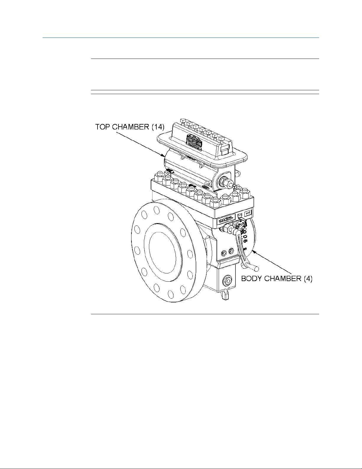
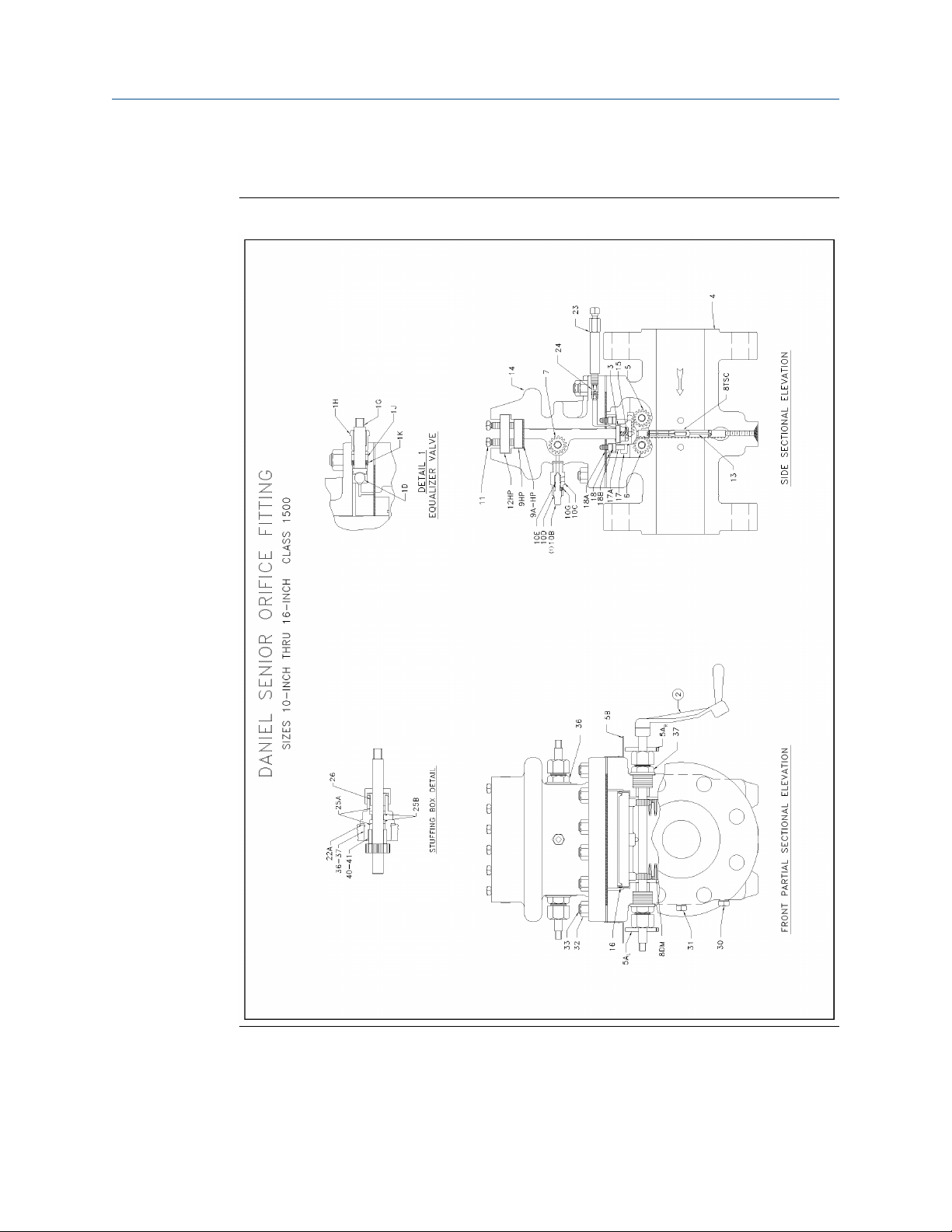
The first chamber, or Body (4), properly positions the orifice plate in the flow stream. The
second chamber, or Top (14), is a temporary holding place for the orifice plate during
removing or installing operations (Refer to Orifice plate installation and removal
instructions).
14 Senior Orifice Fitting
Page 15
Owner and operator manual Introduction
P/N 3-9008-001 October 2019
Important
The unit components have part numbers assigned on appropriate drawings and tables.
Refer to Figure 1-2 thru Figure 1-5 and Table 1-4 thru Table 1-8 for part numbers. Example:
Body (4).
Figure 1-1: Daniel Senior Orifice Fitting - Flangnek option
Therefore, using a Senior may eliminate the need for bypass piping, valves, and other
fittings necessary with conventional orifice fitting installations. Maintenance technicians
can replace and repair all parts of the Senior, including the slide valve assembly, without
removing the Body (4) from the line (refer to Maintain).
Emerson designs and manufactures all Senior units to applicable API-14.3
recommendations and in accordance with selected ANSI, ASME and ASTM specifications.
As an option, Emerson Process Management also designs and manufactures fittings in
compliance with ISO 5167.
Products bearing the "CE" mark are designed and manufactured in compliance with the
European Union Pressure Equipment Directive (PED) 97/23/EC (available on the internet).
Refer to the "Daniel Orifice Fittings Installation and Operating Instructions specific to the
Pressure Equipment Directive", Part Number 3-9008-002 (available on the Emerson
Process Management website).
Owner and operator manual 15
Page 16

Introduction Owner and operator manual
October 2019 P/N 3-9008-001
White papers (available on the Emerson Process Management website, Daniel products
section):
• Upp, E.L. "Application of the Orifice Meter for Accurate Gas Flow Measurement": Daniel
Measurement and Control Inc., Houston, Texas USA (1995)
• Upp, E.L. "Development of Orifice Meter Standards": Daniel Measurement and Control
Inc., Houston, Texas USA (1995)
• Daniel Measurement and Control Inc. "Fundamentals of Orifice Meter Measurement":
Daniel Measurement and Control Inc., Houston, Texas USA (1997)
• Kendrick, Ray. Effects of the Latest Revision of ANSI/API 2530/AGA 3 On Orifice Meter
Primary Elements" Daniel Measurement and Control Inc., Houston, Texas USA (1997)
• Daniel Measurement and Control Inc. "Getting the Best Value From Daniel Senior
Orifice Fittings": Daniel Measurement and Control Inc., Houston, Texas USA (1997)
• Cotton, Galen M. "Pulsation Effects on Gas Measurement": Daniel Measurement and
Control Inc., Houston, Texas USA (1980)
• Husain, Zaki D. "Theoretical Uncertainty of Orifice Flow Measurement": Daniel
Measurement and Control Inc., Houston, Texas USA (1990)
• Daniel Measurement and Control Inc. "Senior Orifice Fitting Technical Guide: DAN-DIF-
TG11-1003 "Daniel Measurement and Control Inc., Houston, Texas USA (2014).
1.4 Conditions and specifications
NOTICE
Follow all the safety and equipment limits recommended in Conditions and specifications
of this manual.
It is the owner's and/or purchaser's responsibility to comply with these parameters.
WARNING
PERSONAL PROTECTION HAZARD
Follow all parameters for the Senior Orifice indicated below.
Failure to comply may result in death and serious injury or equipment damage.
Table 1-2: Conditions and specifications
Product parameters and limitations:
Fluid static
pressures
Refer to ASME/ANSI B16 standards, and your fitting's material of construction,
to determine the maximum operating temperature and pressure of your
Senior. Emerson provides both the fitting's materials of construction and
ASME/ANSI ratings information on the product nameplate.
Fluid phases: Gas, liquid, vapor
Fluids measured: Most fluids
Fluid temperature
parameters:
16 Senior Orifice Fitting
-20° / +160° F (-29° C / +71° C) is the fluid temperature range for this product
based upon the materials of construction (Refer to ASME codes
Consult factory before operating this product outside of the specified
temperature range.
(1)
).
Page 17

Owner and operator manual Introduction
P/N 3-9008-001 October 2019
Table 1-2: Conditions and specifications (continued)
Temperature and
operating
pressure
limitations of
Orifice Plate Seal
materials:
-20° / +160° F (-29° C / +71° C) is the fluid temperature range for this product
based upon the materials of construction (Refer to ASME codes
(1)
) .
The following list describes the most common Orifice Plate Seal material and
their available forms offered for use in Daniel Senior fittings.
Consult factory before operating this product outside of the specified
temperature range.
HNBR: Loose or Bonded:
Material available for "loose" seal rings (2"-10") or "bonded"
seal to orifice plates (12" and larger). Operating pressure is
limited to lesser of ANSI Class MAOP or 1500 psig.
O-ring:
Used with Snap Seal Ring assemblies (2" and larger).
Operating pressure is limited to ANSI Class MAOP.
NBR: Loose or Bonded:
Material available for "loose" seal rings (2"-10") or "bonded"
seal to orifice plates (12" and larger). Operating pressure is
limited to lesser of ANSI Class MAOP or 1500 psig.
FKM: Loose or Bonded:
Material available for "loose" seal rings (2"-10") or "bonded"
seal to orifice plates (12" and larger). Operating pressure is
limited to lesser of ANSI Class MAOP or 1500 psig.
"O" Ring:
Used with Snap Seal Ring assemblies (2" and larger).
Operating pressure is limited to ANSI Class MAOP.
PTFE: Loose:
FFKM: "O" Ring:
Differential
Refer to API -14.3 or ISO 5167, as appropriate to your system.
pressure:
General arrangement dimensions:
See List item.
Time parameters:
See Orifice Plate changing instructions
Components:
Maintenance
intervals:
The owners and users of these products should perform regular scheduled
intervals of maintenance activities. The recommended intervals are every
month or as directed by the owner's maintenance procedures. Examine
components during each scheduled maintenance period, site visits and during
each orifice plate change.
Replace any component that shows signs of wear or when damaged with parts
specified for Daniel products.
Material used for orifice plate seal rings (2" and above).
Operating pressure is limited to ANSI Class MAOP.
Used with Snap Seal Ring assemblies (2" and larger).
Operating pressure is limited to ANSI Class MAOP.
Owner and operator manual 17
Page 18

Introduction Owner and operator manual
October 2019 P/N 3-9008-001
Table 1-2: Conditions and specifications (continued)
Seal replacement: Examine seals during each scheduled maintenance period, site visits and
during each orifice plate change.
Replace any worn or damaged or non-functioning seals with parts specified for
Daniel product.
Fastener torque
verification:
Corrosion
allowance:
Environmental parameters:
Application: Surface and offshore (not for use in subsea applications)
Confined/open: Designed for outdoor use. May be used in well ventilated spaces (buildings/
Site temperature: Recommended atmospheric temperature ranges
Check all fasteners for tightness during each scheduled maintenance period,
site visits and during each orifice plate change.
Use information provided in Section 5.3 as a starting point in establishing the
proper fastener torque values for your particular service environment.
Emerson machines the meter bore of each fitting to close tolerances. This is to
conform to industry measurement standards.
The fitting's meter bore dimensions DO NOT include an allowance for
corrosion.
It is the end user's responsibility to specify a fitting's material of construction
based upon their knowledge of the process fluid and environmental conditions
of an intended service.
Therefore, it is important that the end user to monitor any change in the gas or
liquid composition during monthly exercises, site visits and plate changes that
may create a corrosion concern (Reference: U.S. DOT, CFR Title 49: Part
192.477).
enclosed meter houses). Installation at product owner's discretion.
Maximum: +120 °F (+49 °C),
Minimum: -20 °F (-29 °C).
Site humidity: No limit
Site elevation: No limit
Proximity to
population:
Proximity to
traffic:
Proximity to
equipment:
Interface parameters:
Replacement
parts:
Aftermarket
attachments:
18 Senior Orifice Fitting
Reference: Class 1 location: U.S. DOT, CFR Title 49: Part 192.5.
The owner must protect the fitting from accidental damage by vehicular traffic
or other causes, by either placing the unit at a safe distance from the traffic, or
installing barricades around the unit.
Install the Senior in a well ventilated place, not less than 3 feet (914
millimeters) from any source of ignition or any source of heat which might
damage the unit.
Use only replacement parts specified for Daniel products. Unauthorized parts
and procedures can affect this product's performance and place the safe
operation of your process at risk.
Use of pressure sensing equipment, drain valves, and other accessories (e.g.,
needle valves, multi-port valves, transmitters, 3-pin recorders… etc.) are
permissible. The use of aftermarket equipment must be installed and operated
as directed by the after-market equipment manufacturer, and their warranties
and replacements are not contained within the scope of this document.
Page 19

Owner and operator manual Introduction
P/N 3-9008-001 October 2019
Table 1-2: Conditions and specifications (continued)
Pipe supports: The owner must employ sound engineering principles to design the support
systems for the flow measurement system (or meter tube).
It is important that the design engineer develop a method to support the
entire weight (equipment, piping and fluid) of the system.
The method developed must prevent bending to reduce the potential of
creating unwanted stress at welded joints and flanges. Unwanted stresses may
lead to leaks and may ultimately lead to failure or rupture of the flow
measurement system.
Vandalism/
Tampering:
(1) It is ultimately the responsibility of the Owner or End User to determine suitable materials of
construction suitable for a service conditions.
It is the responsibility of each product owner to protect the Senior from
vandalism, tampering or other unauthorized activity.
Owner and operator manual 19
Page 20

Introduction Owner and operator manual
October 2019 P/N 3-9008-001
1.5 Parts and materials lists
1.5.1 Trim options
Table 1-3: Senior Fitting Trim options
(1)
"A"
"NACE"
AASG
316SS PIC
22CR duplex
Mildly corrosive
Moderately corrosive
Severely corrosive
mpy = mils (0.001") penetration per year of corrosion based on carbon steel
NOTICE
It is the ultimate responsibility of the owner and/or purchaser to specify a fitting's material of
construction, including trim option, based upon their knowledge of the process fluid and
environmental conditions of an intended service.
(1) Unless otherwise noted, materials as listed in the Parts Lists indicate standard "A" Trim product.
For applications outside all parameters listed, please consult the factory.
Materials offered for liquid or dry gaseous, non-corrosive ("sweet")
fluids
Materials offered for dry, non-corrosive ("sour") H2S-containing
gases
Materials offered for liquid or wet gaseous, mildly corrosive ("sour")
H2S-containing fluids
Materials offered for liquid or wet gaseous, moderately corrosive
("sour") H2S-containing fluids
Materials offered for liquid or wet gaseous, severely corrosive
("sour") H2S-containing fluids
≦3.0 mpy
> 3.0 - 8.0 mpy
>8.0 mpy
20 Senior Orifice Fitting
Page 21

Owner and operator manual Introduction
P/N 3-9008-001 October 2019
1.5.2 Daniel Senior Orifice Fitting sizes 2"- 8" 150-900
Figure 1-2: Daniel Orifice Fitting drawing 2"-8" 150-900
Owner and operator manual 21
Page 22

Introduction Owner and operator manual
October 2019 P/N 3-9008-001
All Parts on Daniel Senior Orifice Fittings may be replaced or repaired without removing
the Daniel Senior Orifice Fitting body from the line.
Table 1-4: Daniel Senior Orifice Fitting sizes 2"- 8" 150-600
Item
number
1 * Equalizer valve (complete):
1G*
1H* Packing nut CS (ZP) 1 1 1 1 1
1D*
1K*
1J*
2* Operating wrench Ductile iron 1 1 1 1 1
3
4
5
5A-LH* Indicator plate left-hand Cast aluminum 1 1 1 1 1
5A-RH* Indicator plate right-
5B* Indicator pointer Aluminum 2 2 2 2 2
5C Drive screws 18-8 SS 4 4 4 4 4
6
7
8A*
8DMC
8E-DSC
8TSC
8 MSC
8 SNC
Description Material Quantity required
Size
2" 3" 4" 6" 8"
Stem 316 SS 1 1 1 1 1
Ball Tungsten-Carbide 1 1 1 1 1
Packing washer 17-4PH SS 1 1 1 1 1
Packing ring TFE/PTFE 2 2 2 2 2
Slide valve trip Type 410 1 1 1 1 1
Body Cast carbon steel 1 1 1 1 1
Slide valve shaft 316 SS 1 1 1 1 1
Cast aluminum 1 1 1 1 1
hand
Lower plate carrier shaft 316 SS 1 1 1 1 1
Upper plate carrier shaft 316 SS 1 1 1 1 1
Plate carrier spring pin 18-8 SS 1 1 1 1 1
Plate carrier 316 SS 1 1 1 1 1
Orifice plate sealing unit
150-600
Optional Orifice plate
sealing unit 150-600
Optional Snap Seal Ring
units for special services
Optional Snap Seal Ring
units for special services
NBR (Removable - orifice plate
not included)
TFE/PTFE (Removable - orifice
plate not included)
CS (ZP) (Removable - orifice
plate not included)
CS (ZP) or SS w/O-rings
(Removable - orifice plate not
included)
1 1 1 1 1
1 1 1 1 1
1 1 1 1 1
1 1 1 1 1
9 Sealing bar CS (ZP) 1 1 1 1 1
9A
10B Bleeder Valve (complete)
10C*
22 Senior Orifice Fitting
Sealing bar gasket Composite 1 1 1 1 1
Body CS (ZP) 1 1 1 1 1
Page 23

Owner and operator manual Introduction
P/N 3-9008-001 October 2019
Table 1-4: Daniel Senior Orifice Fitting sizes 2"- 8" 150-600 (continued)
Item
number
10D*
10E*
10G* Set screw Alloy steel 1 1 1 1 1
11* Clamping bar screw Alloy steel (ZP) 4(1) 4(1) 5(1) 6(1) 7(1)
12
13
14
15*
16*
17
17A*
18
18A*
18B*
22A*
23*
24*
Description Material Quantity required
Size
2" 3" 4" 6" 8"
Needle 316 SS 1 1 1 1 1
O-ring Synthetic rubber 1 1 1 1 1
Clamping bar CS (ZP) 1 1 1 1 1
Orifice plate Type 304 SS or 316 SS 1 1 1 1 1
Top Cast carbon steel 1 1 1 1 1
Slide valve springs Inconel X-750 4 4 4 6 6
Slide valve carrier guide 316 SS 2 2 2 2 2
Slide valve carrier Cast carbon steel 1 1 1 1 -
Cast Alloy Iron - - - - 1
Slide valve carrier stop
pin
Slide valve seat 13% chrome SS 1 1 1 1 1
Slide valve seat/top
gasket
Slide valve seat screw Alloy steel phosphate treat 8 10 11 14 16
Bearing plug and
stuffing box gasket
Grease gun (complete) CS (ZP) 1 1 1 1 1
Grease seal double ball
check valve
Carbon steel (ZP) 2 2 2 2 2
Composite 1 1 1 1 1
316 SS 6 6 6 6 6
316 SS with Tungsten-Carbide 1 1 1 1 1
25* Packing nut CS (ZP) 6 6 6 6 6
25A* Packing rings TFE/PTFE 12 12 12 12 12
25B* Centering ring TFE/PTFE 12 12 12 12 12
26* Stuffing box gland 316 SS 6 6 6 6 6
30(1)*
31(1)*
32 Hex nut CS 14 15 15 18 19
33 Stud Alloy steel 14 15 15 18 19
36*
37*
Owner and operator manual 23
Drain valve plug CS (ZP) 1 1 1 1 1
½ N.P.T. plug for
pressure meter tap
Stuffing box (upper) CS (ZP) 2 2 2 2 2
Stuffing box (lower) CS (ZP) 4 4 4 4 4
CS (chemically treated) 2 2 2 2 2
Page 24

Introduction Owner and operator manual
October 2019 P/N 3-9008-001
Table 1-4: Daniel Senior Orifice Fitting sizes 2"- 8" 150-600 (continued)
Item
number
40
41
42*
43*
44*
Description Material Quantity required
Size
2" 3" 4" 6" 8"
Stuffing box sleeve
(upper)
Stuffing box sleeve
(lower)
Plate carrier stop pin CS (ZP) 1 1 1 1 1
Plate carrier stop pin
lock screw
Plate carrier stop pin
access plug
Slide valve lubricant
(boxes)
CS (ZP) 2 2 2 2 2
CS (ZP) 4 4 4 4 4
CS (ZP) 1 1 1 1 1
CS (ZP) 1 1 1 1 1
Castor oil based solid sticks 24 sticks per box
3 3 3 3 3
Notes for Table 1-4:
(1) All Daniel Senior Orifice Fittings are supplied with pipe plugs on the drains only. If pipe
plugs for the measurement tap holes are required, please contact the factory directly.
• Locations of Equalizer Valve (1), Bleeder Valve (10B), and Grease Gun (23) may differ
from diagrams shown in this manual.
• The clamping bar screw quantity and size listed here reflect ones used on our most
common fitting for that size and pressure rating. The actual number and size of
clamping bar screws may vary for that size and pressure rating due to a fitting's
material of construction and configuration. When ordering replacements, or
developing a maintenance program, always confirm the count and size of clamping bar
screws of your fitting.
• Slide Valve Lubricant: 0.38 in (9.53 mm) diameter by 1.5 in (38.1 mm) long is
equivalent to some lubricant manufacturers' "B" size stick. The quantity of lubricant a
fitting described in this manual will require is dependent upon the state and condition
of the fitting. Emerson recommends having one box of lubricant sticks (24 sticks per
box) on-hand when performing maintenance and plate inspection/change procedures.
(*) Indicates interchangeable parts for all line sizes of specified pressure rating(s).
(1) Indicates 1/2" - 13. See Table 1 for clamping bar screw recommended torque values.
General notes for Table 1-4:
• The materials listed in Table 1-4 indicate standard "NACE" trim.
• Materials of some items listed in Table 1-4 are changed for the "AASG" trimmed fittings.
• Several available trim options are shown in Table 1-3.
• Other trim options available upon request. Consult factory.
• Bolded item numbers are for parts which are fluid media PIC (parts in contact).
24 Senior Orifice Fitting
Page 25

Owner and operator manual Introduction
P/N 3-9008-001 October 2019
When ordering parts, please specify
• Catalog number
• Size
• Serial number
• Item number
• Material
• Quantity of each item required
(1)
(1) Catalog number, size and serial number can be found on the fitting nameplate. Part item numbers and part materials for
"NACE" trim only are found in Daniel Senior Orifice Fitting sizes 2"- 8" 150-900.
Owner and operator manual 25
Page 26

Introduction Owner and operator manual
October 2019 P/N 3-9008-001
All Parts on Daniel Senior Orifice Fittings may be replaced or repaired without removing
the Daniel Senior Orifice Fitting body from the line.
Table 1-5: Daniel Senior Orifice Fitting sizes 2"-8" 900
Item
number
1 * Equalizer valve (complete):
1G*
1H* Packing nut CS (ZP) 1 1 1 1 1
1D*
1K*
1J*
2* Operating wrench Ductile iron 1 1 1 1 1
3
4
5
5A-LH* Indicator plate left-hand Cast aluminum 1 1 1 1 1
5A-RH* Indicator plate right-
5B* Indicator pointer Aluminum 2 2 2 2 2
5C Drive screws 18-8 SS 4 4 4 4 4
6
7
8A*
8DMC
8TSC
8 MSC
8 SNC
Description Material Quantity required
Size
2" 3" 4" 6" 8"
Stem 316 SS 1 1 1 1 1
Ball 18-8 SS 1 1 1 1 1
Packing washer 17-4PH SS 1 1 1 1 1
Packing ring TFE/PTFE 2 2 2 2 2
Slide valve trip Type 410 SS 1 1 1 1 1
Body Cast carbon steel 1 1 1 1 1
Slide valve shaft 316 SS 1 1 1 1 1
Cast aluminum 1 1 1 1 1
hand
Lower plate carrier shaft 316 SS 1 1 1 1 1
Upper plate carrier shaft 316 SS 1 1 1 1 1
Plate carrier spring pin 18-8 SS 1 1 1 1 1
Plate carrier 316 SS 1 1 1 1 1
Orifice plate sealing unit
alternate seals available
see catalog - #500
Optional Snap Seal Ring
units for special services
Optional Snap Seal Ring
units for special services
PTFE (Removable - orifice plate
not included)
CS (ZP) or 316 SS (plate not
included)
CS (ZP) or 316 SS w/O-rings
(plate not included)
1 1 1 1 1
1 1 1 1 1
1 1 1 1 1
9 Sealing bar CS (ZP) 1 1 1 1 1
9A
10B Bleeder Valve (Complete)
10C*
10D*
10E*
26 Senior Orifice Fitting
Sealing bar gasket Composite 1 1 1 1 1
Body CS (ZP) 1 1 1 1 1
Needle 316 SS 1 1 1 1 1
O-ring Synthetic rubber 1 1 1 1 1
Page 27

Owner and operator manual Introduction
P/N 3-9008-001 October 2019
Table 1-5: Daniel Senior Orifice Fitting sizes 2"-8" 900 (continued)
Item
number
10G* Set screw Alloy steel 1 1 1 1 1
11* Clamping bar screw Alloy steel (ZP) 4(1) 4(1) 5(1) 6(1) 7(2)
12 Clamping bar CS (ZP) 1 1 1 1 1
13
14
15*
16*
17
17A*
18
18A*
18B*
22A*
23*
24*
Description Material Quantity required
Size
2" 3" 4" 6" 8"
Orifice plate Type 304 SS or 316 SS 1 1 1 1 1
Top Cast carbon steel 1 1 1 1 1
Slide valve springs 316 SS 4 4 4 6 6
Slide valve carrier guide 316 SS 2 2 2 2 2
Slide valve carrier Cast carbon steel 1 1 1 1 -
Cast Alloy Iron - - - - 1
Slide valve carrier stop
pin
Slide valve seat Cast alloy iron 1 1 1 1 -
Slide valve seat/top
gasket
Slide valve seat screw Alloy steel phosphate treat 8 10 11 14 16
Bearing plug and
stuffing box gasket
Grease gun (complete) CS (ZP) 1 1 1 1 1
Grease seal double ball
check valve
Carbon steel (ZP) 2 2 2 2 2
Cast iron - - - - 1
Composite 1 1 1 1 1
316 SS 6 6 6 6 6
316 SS with chrome-steel balls 1 1 1 1 1
25* Packing nut CS (ZP) 6 6 6 6 6
25A*
25B*
26* Stuffing box gland 316 SS 6 6 6 6 6
30(1)*
31(1)*
32 Hex nut CS 14 15 15 18 20
33 Stud Alloy steel 14 15 15 18 20
36*
37*
40
Owner and operator manual 27
Packing rings TFE/PTFE 12 12 12 12 12
Centering ring TFE/PTFE 12 12 12 12 12
Drain valve plug CS (ZP) 1 1 1 1 1
½ N.P.T. plug for
pressure meter tap
Stuffing box (upper) CS (ZP) 2 2 2 2 2
Stuffing box (lower) CS (ZP) 4 4 4 4 4
Stuffing box sleeve
(upper)
CS (chemically treated) 2 2 2 2 2
CS (ZP) 2 2 2 2 2
Page 28

Introduction Owner and operator manual
October 2019 P/N 3-9008-001
Table 1-5: Daniel Senior Orifice Fitting sizes 2"-8" 900 (continued)
Item
number
41
42*
43*
44*
Description Material Quantity required
Size
2" 3" 4" 6" 8"
Stuffing box sleeve
(lower)
Plate carrier stop pin CS (ZP) 1 1 1 1 1
Plate carrier stop pin
lock screw
Plate carrier stop pin
access plug
Slide valve lubricant
(boxes)
CS (ZP) 4 4 4 4 4
CS (ZP) 1 1 1 1 1
CS (ZP) 1 1 1 1 1
Castor oil based solid sticks 24 sticks per box
3 3 3 3 3
Notes for Table 1-5:
(1) All Daniel Senior Orifice Fittings are supplied with pipe plugs on the drains only. If pipe
plugs for the measurement tap holes are required, please contact the factory directly.
• Locations of Equalizer Valve (1), Bleeder Valve (10B), and Grease Gun (23) may differ
from diagrams shown in this manual.
• The clamping bar screw quantity and size listed here reflect ones used on our most
common fitting for that size and pressure rating. The actual number and size of
clamping bar screws may vary for that size and pressure rating due to a fitting's
material of construction and configuration. When ordering replacements, or
developing a maintenance program, always confirm the count and size of clamping bar
screws of your fitting.
• Slide Valve Lubricant: 0.38 in (9.53 mm) diameter by 1.5 in (38.1 mm) long is
equivalent to some lubricant manufacturers' "B" size stick. The quantity of lubricant a
fitting described in this manual will require is dependent upon the state and condition
of the fitting. Emerson recommends having one box of lubricant sticks (24 sticks per
box) on-hand when performing maintenance and plate inspection/change procedures.
(*) Indicates interchangeable parts for all line sizes of specified pressure rating(s).
(1) Indicates 1/2" - 13. See Clamping bar screw (LINK) for clamping bar screw
recommended torque values.
(2) Indicates 5/8" - 11. See Clamping bar screw (LINK) for clamping bar screw
recommended torque values.
General notes for Table 1-5:
• The materials listed in Table 1-5 indicate standard "A" trim.
• Materials of some items listed in Table 1-5 are changed for "NACE" and "AASG" trimmed
fittings.
• Several available trim options are shown in Table 1-3.
• Other trim options available upon request. Consult factory.
28 Senior Orifice Fitting
Page 29

Owner and operator manual Introduction
P/N 3-9008-001 October 2019
• Bolded item numbers are for parts which are fluid media PIC (parts in contact).
When ordering parts, please specify
• Catalog number
• Size
• Serial number
• Item number
• Material
• Quantity of each item required
(2)
(2) Catalog number, size and serial number can be found on the fitting nameplate. Part item numbers and part materials for
"A" trim only are found in Table 1-5.
Owner and operator manual 29
Page 30
Introduction Owner and operator manual
October 2019 P/N 3-9008-001
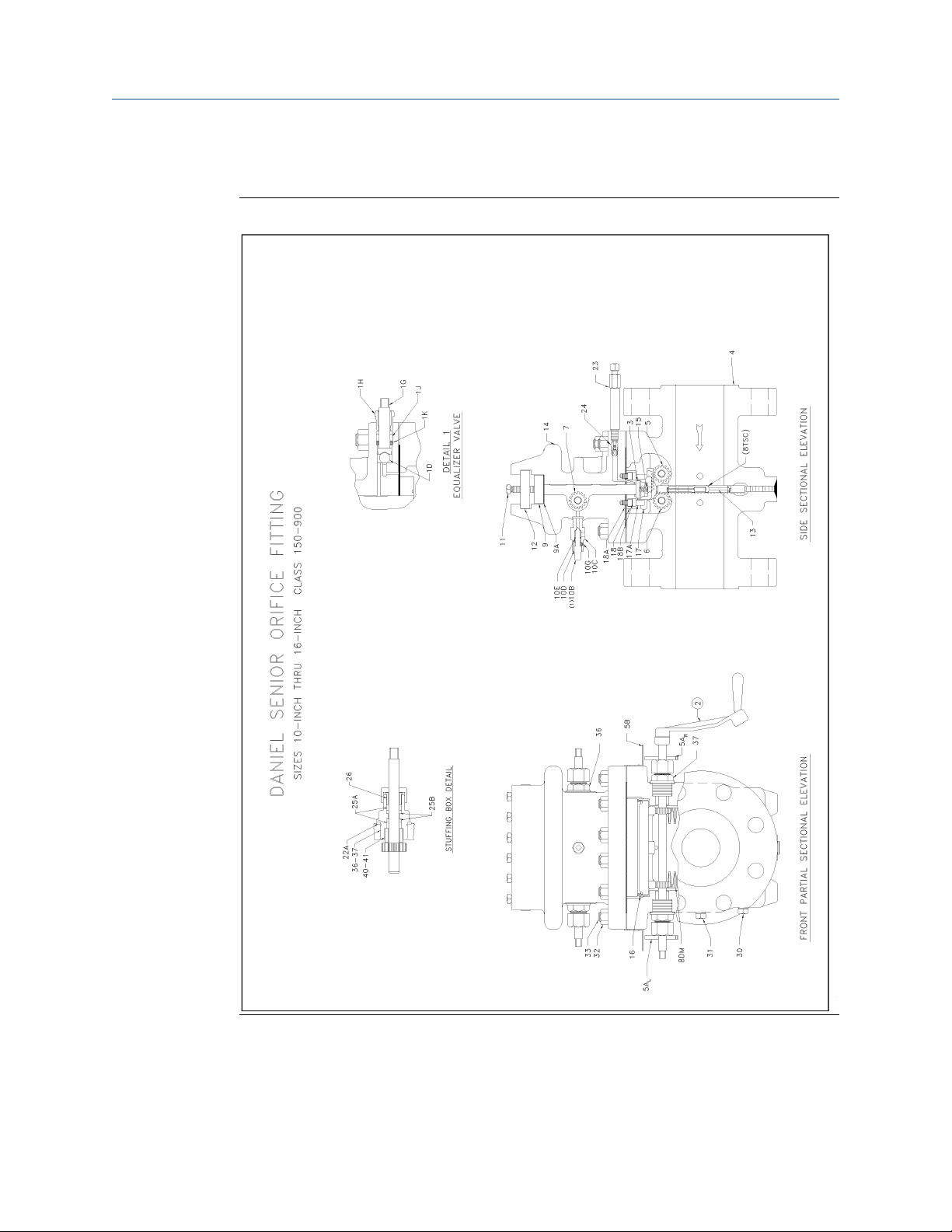
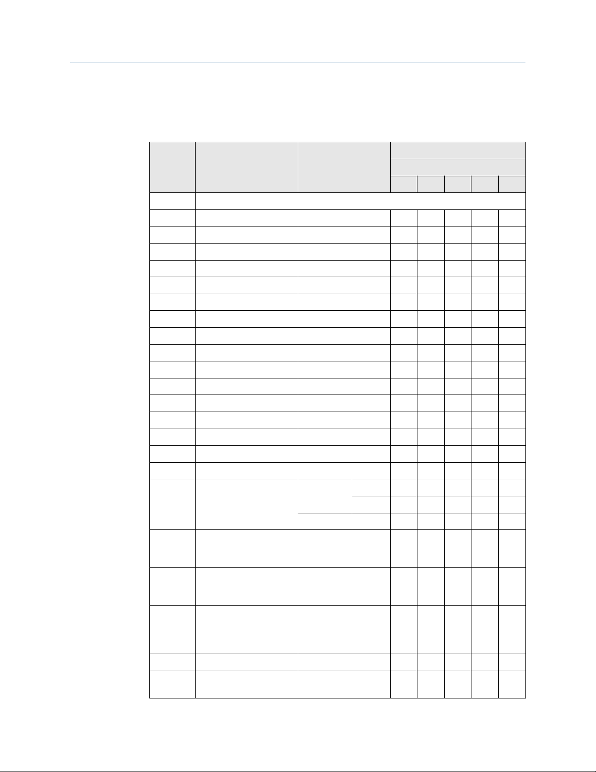
1.5.3 Daniel Senior Orifice Fitting sizes 10"-16" 150-900
Figure 1-3: Daniel Senior Orifice Fitting drawing sizes 10"-16" 150-900
30 Senior Orifice Fitting
Page 31

Owner and operator manual Introduction
P/N 3-9008-001 October 2019
All Parts on Daniel Senior Orifice Fittings may be replaced or repaired without removing
the Daniel Senior Orifice Fitting body from the line.
Table 1-6: Daniel Senior Orifice Fitting sizes 10"-16" 150-900
Item
Number
1* Equalizer valve (complete):
1G*
1H* Packing nut CS (ZP) 1 1 1 1
1D*
1K*
1J*
2* Operating wrench Ductile iron 1 1 1 2
3
4
5
5A-LH* Indicator plate left-
5A-RH Indicator plate right-
5B* Indicator pointer Aluminum 2 2 2 2
Description Material Quantity required
Size
10" 12" 14" 16"
Stem 316 SS 1 1 1 1
Ball 18-8 SS 1 1 1 1
Packing washer 17-4PH SS 1 1 1 1
Packing ring TFE/PTFE 2 2 2 2
Slide valve trip Type 410 SS 1 1 1 1
Body Cast carbon steel 1 1 1 1
Slide valve shaft 316 SS 1 1 1 1
Cast aluminum 1 1 1 1
hand
Cast aluminum 1 1 1 1
hand
5C Drive screws 18-8 SS 4 4 4 4
6
7
8DM
8E-DS
8E-DVS
8TS
8MS
8SN
Lower plate carrier
shaft
Upper plate carrier
shaft
Plate carrier 316 SS 1 1 1 1
Orifice plate sealing
unit 150-600
Orifice plate sealing
unit 150-600
Orifice plate sealing
unit 150-600, 900
optional alternate for
150-600
Optional sealing units
for special services
Optional snap seal
ring units for special
services
316 SS 1 1 1 1
316 SS 1 1 1 1
NBR (Removable - orifice plate
not included)
FKM (Bonded to both faces of
the orifice plate)
TFE/PTFE (removable) 1 1 1 1
CS (ZP) or 316 SS (Removable
- orifice plate not included)
CS (ZP) or 316 SS w/O-rings
(Removable - orifice plate not
included)
1 - - -
- 1 1 1
1 1 1 1
1 1 1 1
Owner and operator manual 31
Page 32

Introduction Owner and operator manual
October 2019 P/N 3-9008-001
Table 1-6: Daniel Senior Orifice Fitting sizes 10"-16" 150-900 (continued)
Item
Number
9 Sealing bar CS (ZP) 1 1 1 1
9A
10B* Bleeder valve
10C*
10D*
10E*
10G*
10F
10H
11* Clamping bar screw Alloy steel
12 Clamping bar CS (ZP) 1 1 1 1
13
14
15*
16*
17
17A*
18
Description Material Quantity required
Size
10" 12" 14" 16"
Sealing bar gasket Composite 1 1 1 1
1 1 1 (Complete 10" - 14"
only):
Body CS (ZP) 1 1 1 -
Needle 316 SS 1 1 1 -
O-ring Synthetic rubber 1 1 1 -
Set screw Alloy steel 1 1 1 -
Bleeder valve
(Complete)
Bleeder valve nipple - - - 1
Orifice Plate Type 304 SS or 316 SS 1 1 1 1
Top Cast Carbon steel 1 1 1 1
Slide valve springs 316 SS 6 7 8 10
Slide valve carrier
guide
Slide valve carrier Cast Carbon Steel 1 1 1 1
Slide valve carrier stop
pin
Slide valve seat Cast Alloy
CS (ZP) w/410 SS - - - 1
150-600 8(1) 10(1) 11(1) 12(1)
(ZP)
316 SS 2 2 2 2
CS (ZP) 2 2 2 2
Iron
900 8(2) 10(2) 22(2) 28(2)
150-600 1 1 1 1
TY 410 SS 900 1 - - -
17-4PH SS 900 - 1 1 1
18A
18B*
22A*
23*
32 Senior Orifice Fitting
Slide valve seat/top
gasket
Slide valve seat screw Alloy Steel Phosphate treat 18 20 24 26
Bearing Plug and
stuffing box gasket
Grease gun
(Complete)
Composite 1 1 1 1
316 SS 6 6 6 6
CS (ZP) 1 1 1 2
Page 33

Owner and operator manual Introduction
P/N 3-9008-001 October 2019
Table 1-6: Daniel Senior Orifice Fitting sizes 10"-16" 150-900 (continued)
Item
Number
24*
25* Packing Nut CS (ZP) 6 6 6 6
25A*
25B*
26* Stuffing box gland 316 SS 6 6 6 6
30(1)*
31(1)*
32 Hex nut CS 22 22 24 28
33 Stud Alloy steel 22 22 24 28
36*
37*
40
41
Description Material Quantity required
Size
10" 12" 14" 16"
Grease seal double
ball check valve
Packing Rings TFE/PTFE 12 12 12 12
Centering ring TFE/PTFE 12 12 12 12
Drain Valve plug CS (ZP) 1 1 1 1
½ NPT Plug for
pressure meter tap
Stuffing box body
(upper)
Stuffing box body
(lower)
Stuffing box sleeve
(upper)
Stuffing box sleeve
(lower)
316 SS with chrome-steel balls 1 1 1 2
CS (chemically treated) 2 2 2 2
CS (ZP) 2 2 2 2
CS (ZP) 4 4 4 4
CS (ZP) 2 2 2 2
CS (ZP) 4 4 4 4
Slide valve lubricant
(boxes)
Castor oil based solid sticks 24 sticks per box
3 3 3 3
Notes for Daniel Senior Orifice Fitting sizes 10"-16" 150-900
(1) All Daniel Senior Orifice Fittings are supplied with pipe plugs on the drains only. If pipe
plugs for the measurement tap holes are required, please contact the factory directly.
• Locations of Equalizer Valve (1), Bleeder Valve (10B), and Grease Gun (23) may differ
from diagrams shown in this manual.
• The clamping bar screw quantity and size listed here reflect ones used on our most
common fitting for that size and pressure rating. The actual number and size of
clamping bar screws may vary for that size and pressure rating due to a fitting's
material of construction and configuration. When ordering replacements, or
developing a maintenance program, always confirm the count and size of clamping bar
screws of your fitting.
• Slide Valve Lubricant: 0.38 in (9.53 mm) diameter by 1.5 in (38.1 mm) long is
equivalent to some lubricant manufacturers' "B" size stick. The quantity of lubricant a
fitting described in this manual will require is dependent upon the state and condition
of the fitting. Emerson recommends having one box of lubricant sticks (24 sticks per
box) on-hand when performing maintenance and plate inspection/change procedures.
Owner and operator manual 33
Page 34

Introduction Owner and operator manual
October 2019 P/N 3-9008-001
(*) Indicates interchangeable parts for all line sizes of specified pressure rating(s).
(1) Indicates 1/2" - 13. See Clamping bar screw (LINK) for clamping bar screw
recommended torque values.
(2) Indicates 5/8" - 11. See Clamping bar screw (LINK) for clamping bar screw
recommended torque values.
General notes Daniel Senior Orifice Fitting sizes 10"-16" 150-900:
• The materials listed in Daniel Senior Orifice Fitting sizes 10"-16" 150-900 indicate
standard "A" trim.
• Materials of some items listed in Daniel Senior Orifice Fitting sizes 10"-16" 150-900 are
changed for "NACE" and "AASG" trimmed fittings.
• Several available trim options are shown in Table 1-3.
• Other trim options available upon request. Consult factory.
• Bolded part numbers are for items which are fluid media PIC (parts in contact).
When ordering parts, please specify
• Catalog number
• Size
• Serial number
• Item number
• Material
• Quantity of each item required
(3)
(3) Catalog number, size and serial number can be found on the fitting nameplate. Part item numbers and part materials for
"A" trim only are found in Daniel Senior Orifice Fitting sizes 10"-16" 150-900.
34 Senior Orifice Fitting
Page 35
Owner and operator manual Introduction
P/N 3-9008-001 October 2019
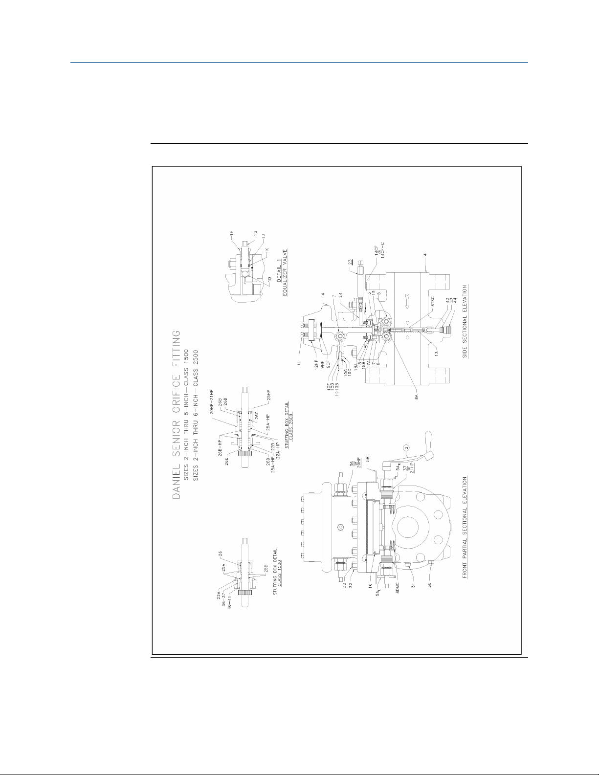
1.5.4 Daniel Senior Orifice Fitting sizes 2"-8" 1500 and 2"-6" 2500
Figure 1-4: Daniel Senior Orifice Fitting drawing sizes 2"-8" 1500 and 2"-6" 2500
Owner and operator manual 35
Page 36
Introduction Owner and operator manual
October 2019 P/N 3-9008-001
All Parts on Daniel Senior Orifice Fittings may be replaced or repaired without removing
the Daniel Senior Orifice Fitting body from the line.
Table 1-7: Daniel Senior Orifice Fitting sizes 2"- 8" 1500 and 2"-6" 2500
Item
number
1 Equalizer valve (complete):
1G*
1H* Packing nut CS (ZP) 1 1 1 1 1
1D*
1K*
1J*
2* Operating wrench Ductile iron 1 1 1 1 1
3
4
5
5A-LH* Indicator plate left-hand Cast aluminum 1 1 1 1 1
5A-RH Indicator plate right-hand Cast aluminum 1 1 1 1 1
5B* Indicator pointer Aluminum 2 2 2 2 2
5C Drive screws 18-8 SS 4 4 4 4 4
6
7
8A*
8DMC
Description Material Quantity required
Size
2" 3" 4" 6" 8"
Stem 316 SS 1 1 1 1 1
Ball 18-8 SS 1 1 1 1 1
Packing washer 17-4PH SS 1 1 1 1 1
Packing ring TTFE/PTFE 2 2 2 2 2
Slide valve strip Type 410 SS 1 1 1 1 1
Body Cast carbon steel 1 1 1 1 1
Slide valve shaft 316 SS 1 1 1 1 1
Lower plate carrier shaft 316 SS 1 1 1 1 1
Upper plate carrier shaft 316 SS 1 1 1 1 1
Plate carrier spring pin 18-8 SS 1 1 1 1 1
Plate carrier 316 SS 1500 1 1 1 1 1
2500 - - - 1 -
CS (ZP) 2500 1 1 1 - -
8TSC
8 MSC
8 SNC
9-HP
9A-CF
36 Senior Orifice Fitting
Orifice plate sealing unit TTFE/PTFE (Removable
- orifice plate not
included)
Optional Snap Seal Ring
units for special services
Optional Snap Seal Ring
units for special services
Sealing Bar CS (ZP) 1 1 1 1 1
Sealing Bar Gasket (Oring)
CS (ZP) or 316 SS
(Removable - orifice
plate not included)
CS (ZP) or 316 SS w/Orings (Removable orifice plate not
included)
Synthetic rubber 1 1 1 1 1
1 1 1 1 1
1 1 1 1 1
1 1 1 1 1
Page 37

Owner and operator manual Introduction
P/N 3-9008-001 October 2019
Table 1-7: Daniel Senior Orifice Fitting sizes 2"- 8" 1500 and 2"-6" 2500 (continued)
Item
number
10B* Bleeder valve (complete):
10C*
10D*
10E*
10G* Set screw Alloy steel 1 1 1 1 1
11* Clamping bar screw (See
12HP Clamping bar CS (ZP) 1 1 1 1 1
13
14
14CF
14CF-C
15*
16*
17
Description Material Quantity required
Size
2" 3" 4" 6" 8"
Body CS (ZP) 1 1 1 1 1
Needle 316 SS 1 1 1 1 1
O-ring Synthetic rubber 1 1 1 1 1
Alloy steel
Note 3 in NOTES for this
table)
Orifice plate Type 304 SS or 316 SS 1 1 1 1 1
Top Cast carbon steel 1 1 1 1 1
Body-top gasket ("o-ring) Special
Body-top gasket (MaleFemale Joint) Not
illustrated
Slide valve springs 316 SS 4 4 4 6 6
Slide valve carrier guide 316 SS 2 2 2 2 2
Slide valve carrier Cast carbon steel 1 1 1 1 -
(ZP)
compound
Synthetic
Rubber
1500 8(2) 10(2) 12(2) 14(2) 16(2)
2500 10(2) 10(2) 12(2) 14(2) -
1500 1 1 1 1 1
2500 1 1 1 1 -
Cast Alloy Iron - - - - 1
17A*
18
18A
18B*
20 HP
21 HP
22A*
22A -HP*
22B*
Owner and operator manual 37
Slide valve carrier stop
pin
Slide valve seat 13% chrome SS 1 1 1 1 1
Slide valve seat/top
gasket
Slide valve seat screw Alloy steel
Stuffing Box (Upper) CS (ZP) 2500 2 2 2 2 0
Stuffing Box (Lower) CS (ZP) 2500 4 4 4 4 0
Bearing plug and stuffing
box gasket
Bearing plug and stuffing
box gasket
Bearing plug and stuffing
box O-ring
Carbon steel (ZP) 2 2 2 2 2
Composite 1500 1 1 1 1 1
2500 Assembled metal-to-metal
1500 8 10 11 14 16
phosphate
treat
316 SS 1500 6 6 6 6 6
316 SS 2500 6 6 6 6 -
Synthetic
rubber
2500 10 10 11 14 12
2500 6 6 6 6 -
Page 38

Introduction Owner and operator manual
October 2019 P/N 3-9008-001
Table 1-7: Daniel Senior Orifice Fitting sizes 2"- 8" 1500 and 2"-6" 2500 (continued)
Item
number
23*
24*
25* Packing nut CS (ZP) 1500 6 6 6 6 6
25HP* Packing nut CS (ZP) 2500 6 6 6 6 6
25A*
25A-HP*
25B*
25B-HP*
26*
26B* External Stuffing box
26E*
26C*
26D*
30(1)*
31(1)*
Description Material Quantity required
Size
2" 3" 4" 6" 8"
Grease gun (complete) CS (ZP) 1 1 1 1 1
Grease seal double ball
check valve
Packing rings TTFE/PTFE 1500 12 12 12 12 12
Packing rings TTFE/PTFE 2500 Varies with fitting size
Centering ring TTFE/PTFE 1500 12 12 12 12 12
Centering ring TTFE/PTFE 2500 12 12 12 12 -
Stuffing box gland 316 SS 1500 6 6 6 6 6
gland
Internal Stuffing box
gland
Stuffing box gland O-ring Synthetic
Stuffing box gland O-ring Synthetic
Drain valve plug CS (ZP) 1 1 1 1 1
½ N.P.T. plug for
pressure meter tap
316 SS with chromesteel balls
316 SS 2500 6 6 6 6 -
316 SS 2500 6 6 6 6 -
2500 6 6 6 6 rubber
2500 12 12 12 12 rubber
CS (chemically
treated)
1 1 1 1 1
2 2 2 2 2
32 Hex nut CS 1500 14 14 16 18 18
2500 16 16 16 18 -
33 Stud Alloy steel 1500 14 14 16 18 18
2500 16 16 16 18 -
36*
37*
40
41
42*
43*
38 Senior Orifice Fitting
Stuffing box (upper) CS (ZP) 1500 2 2 2 2 2
Stuffing box (lower) CS (ZP) 1500 4 4 4 4 4
Stuffing box sleeve
(upper)
Stuffing box sleeve
(lower)
Plate carrier stop pin CS (ZP) 1 1 1 1 1
Plate carrier stop pin lock
screw
CS (ZP) 1500 2 2 2 2 2
CS (ZP) 1500 4 4 4 4 4
CS (ZP) 1 1 1 1 1
Page 39

Owner and operator manual Introduction
P/N 3-9008-001 October 2019
Table 1-7: Daniel Senior Orifice Fitting sizes 2"- 8" 1500 and 2"-6" 2500 (continued)
Item
number
44*
Description Material Quantity required
Size
2" 3" 4" 6" 8"
Plate carrier stop pin
access plug
Slide valve lubricant
(boxes)
CS (ZP) 1 1 1 1 1
Castor oil based solid
sticks - 24 sticks per
box
3 3 3 3 3
Notes for Daniel Senior Orifice Fitting sizes 2"-8" 1500 and 2"-6" 2500
(1) All Daniel Senior Orifice Fittings are supplied with pipe plugs on the drains only. If pipe
plugs for the measurement tap holes are required, please contact the factory directly.
• Locations of Equalizer Valve (1), Bleeder Valve (10B), and Grease Gun (23) may differ
from diagrams shown in this manual.
• The clamping bar screw quantity and size listed here reflect ones used on our most
common fitting for that size and pressure rating. The actual number and size of
clamping bar screws may vary for that size and pressure rating due to a fitting's
material of construction and configuration. When ordering replacements, or
developing a maintenance program, always confirm the count and size of clamping bar
screws of your fitting.
• Slide Valve Lubricant: 0.38 in (9.53 mm) diameter by 1.5 in (38.1 mm) long is
equivalent to some lubricant manufacturers' "B" size stick. The quantity of lubricant a
fitting described in this manual will require is dependent upon the state and condition
of the fitting. Emerson recommends having one box of lubricant sticks (24 sticks per
box) on-hand when performing maintenance and plate inspection/change procedures.
(*) Indicates interchangeable parts for all line sizes of specified pressure rating(s).
(2) Indicates 5/8" - 11. See Clamping bar screw (LINK) for clamping bar screw
recommended torque values.
General notes for Daniel Senior Orifice Fitting sizes 2"-8" 1500 and 2"-6" 2500
• Most parts available in other materials upon customer request.
• CS (Carbon Steel), CRS (Cold Rolled Steel), NPT (National Pipe Thread), ZP (Zinc
Plated).
• The materials listed in Daniel Senior Orifice Fitting sizes 2"-8" 1500 and 2"-6" 2500
indicate standard "A" trim.
• Materials of some items listed in Daniel Senior Orifice Fitting sizes 2"-8" 1500 and 2"-6"
2500 are changed for "NACE" and "AASG" trimmed fittings.
• Several available trim options are shown in Table 1-3.
• Other trim options available upon request. Consult factory.
• Bolded part numbers are for items which are fluid media PIC (parts in contact).
Owner and operator manual 39
Page 40

Introduction Owner and operator manual
October 2019 P/N 3-9008-001
When ordering parts, please specify
• Catalog number
• Size
• Serial number
• Item number
• Material
• Quantity of each item required
(4)
(4) Catalog number, size and serial number can be found on the fitting nameplate. Part item numbers and part materials for
"A" trim only are found in Daniel Senior Orifice Fitting sizes 2"-8" 1500 and 2"-6" 2500.
40 Senior Orifice Fitting
Page 41
Owner and operator manual Introduction
P/N 3-9008-001 October 2019
1.5.5 Daniel Senior Orifice Fitting sizes 10"- 16" 1500
Figure 1-5: Daniel Senior Orifice Fitting drawing sizes 10"- 16" 1500
Owner and operator manual 41
Page 42

Introduction Owner and operator manual
October 2019 P/N 3-9008-001
All Parts on Daniel Senior Orifice Fittings may be replaced or repaired without removing
the Daniel Senior Orifice Fitting body from the line.
Table 1-8: Daniel Senior Orifice Fitting sizes 10"- 16" 1500
Item
Number
1* Equalizer valve (complete):
1G*
1H* Packing nut CS (ZP) 1 1 1 1
1D*
1K*
1J*
2* Operating wrench Ductile iron 1 1 1 2
3
4
5
5A-LH* Indicator plate left-hand Cast aluminum 1 1 1 1
5A-RH Indicator plate right-
5B* Indicator pointer Aluminum 2 2 2 2
5C Drive screws 18-8 SS 4 4 4 4
6
7
8DM
8TS
8MS
8SN
9HP
9A-HP
Description Material Quantity required
Size
10" 12" 14" 16"
Stem 316 SS 1 1 1 1
Ball 18-8 SS 1 1 1 1
Packing washer 17-4PH SS 1 1 1 1
Packing ring TFE/PTFE 2 2 2 2
Slide valve trip Type 410 SS 1 1 1 1
Body Cast carbon steel 1 1 1 1
Slide valve shaft 316 SS 1 1 1 1
Cast aluminum 1 1 1 1
hand
Lower plate carrier shaft 316 SS 1 1 1 1
Upper plate carrier shaft 316 SS 1 1 1 1
Plate carrier 316 SS 1 1 1 1
Orifice plate sealing unit TFE/PTFE (Removable -
orifice plate not included)
Optional sealing units
for special services
Optional snap seal ring
units for special services
Sealing bar CS (ZP) 1 1 1 1
Sealing bar gasket Composite 1 1 1 1
CS (ZP) or 316 SS
(Removable - orifice plate
w/O-rings not included)
CS (ZP) or 316 SS
(Removable - orifice plate
w/O-rings not included)
1 1 1 1
1 1 1 1
1 1 1 1
10B* Bleeder valve
(Complete)
10C*
10D*
42 Senior Orifice Fitting
Body CS (ZP) 1 1 1 -
Needle 316 SS 1 1 1 -
1 1 1 -
Page 43

Owner and operator manual Introduction
P/N 3-9008-001 October 2019
Table 1-8: Daniel Senior Orifice Fitting sizes 10"- 16" 1500 (continued)
Item
Number
10E*
10G* Set screw Alloy steel 1 1 1 -
10F
10H
11* Clamping bar screw Alloy steel (ZP) 20(2) 22(2) 22(2) 28(2)
12HP Clamping bar CS (ZP) 1 1 1 1
13
14
15*
16*
17
17A*
18
Description Material Quantity required
Size
10" 12" 14" 16"
O-ring Synthetic rubber 1 1 1 -
Bleeder valve
(Complete)
Bleeder valve nipple CS (ZP) - - - 1
Orifice Plate Type 304 SS or 316 SS 1 1 1 1
Top Cast Carbon steel 1 1 1 1
Slide valve springs 316 SS 6 7 8 10
Slide valve carrier guide 316 SS 2 2 2 2
Slide valve carrier Cast Carbon Steel 1 1 1 1
Slide valve carrier stop
pin
Slide valve seat Type 410 SS 1 - - -
CS (ZP) w/410 SS - - - 1
Carbon steel 2 2 2 2
17-4PH SS - 1 1 -
Duplex SS (UNS S31803) - - - 1
18A
18VSG
18BTG
18B*
22A*
23*
24*
25* Packing Nut CS (ZP) 6 6 6 6
25A*
25B*
26*
30(1)*
31(1)*
Slide valve seat/top
gasket
Slide valve seat gasket Composite (not shown) - - 1 1
Body/top gasket Composite (not shown) - - 1 1
Slide valve seat screw Alloy Steel Phosphate treat 18 20 24 26
Bearing Plug and
stuffing box gasket
Grease gun (Complete) CS (ZP) 1 1 1 2
Grease seal double ball
check valve
Packing Rings TFE/PTFE 12 12 12 12
Centering ring TFE/PTFE 12 12 12 12
Stuffing box gland 316 SS 6 6 6 6
Drain Valve plug CS (ZP) 1 1 1 1
½ NPT Plug for pressure
meter tap
Composite 1 1 1 1
316 SS 6 6 6 6
316 SS with chrome-steel
balls
CS (chemically treated) 2 2 2 2
1 1 1 2
Owner and operator manual 43
Page 44

Introduction Owner and operator manual
October 2019 P/N 3-9008-001
Table 1-8: Daniel Senior Orifice Fitting sizes 10"- 16" 1500 (continued)
Item
Number
32 Hex nut CS 22 22 28 32
33 Stud Alloy steel 22 22 28 32
36*
37*
40
41
Description Material Quantity required
Size
10" 12" 14" 16"
Stuffing box body
(upper)
Stuffing box body
(lower)
Stuffing box sleeve
(upper)
Stuffing box sleeve
(lower)
Slide valve lubricant
(boxes)
CS (ZP) 2 2 2 2
CS (ZP) 4 4 4 4
CS (ZP) 2 2 2 2
CS (ZP) 4 4 4 4
Castor Oil based solid sticks
- 24 sticks per box
3 3 3 3
Notes for Daniel Senior Orifice Fitting sizes 10"- 16" 1500
(1) All Daniel Senior Orifice Fittings are supplied with pipe plugs on the drains only. If pipe
plugs for the measurement tap holes are required, please contact the factory directly.
• Locations of Equalizer Valve (1), Bleeder Valve (10B), and Grease Gun (23) may differ
from diagrams shown in this manual.
• The clamping bar screw quantity and size listed here reflect ones used on our most
common fitting for that size and pressure rating. The actual number and size of
clamping bar screws may vary for that size and pressure rating due to a fitting's
material of construction and configuration. When ordering replacements, or
developing a maintenance program, always confirm the count and size of clamping bar
screws of your fitting.
• Slide Valve Lubricant: 0.38 in (9.53 mm) diameter by 1.5 in (38.1 mm) long is
equivalent to some lubricant manufacturers' "B" size stick. The quantity of lubricant a
fitting described in this manual will require is dependent upon the state and condition
of the fitting. Emerson recommends having one box of lubricant sticks (24 sticks per
box) on-hand when performing maintenance and plate inspection/change procedures.
(*) Indicates interchangeable parts for all line sizes of specified pressure rating(s).
(2) Indicates 5/8" - 11. See Clamping bar screw (LINK) for clamping bar screw
recommended torque values.
General notes for Daniel Senior Orifice Fitting sizes 10"- 16" 1500:
• The materials listed in Daniel Senior Orifice Fitting sizes 10"- 16" 1500 indicate standard
"A" trim.
• Materials of some items listed in Daniel Senior Orifice Fitting sizes 10"- 16" 1500 are
changed for "NACE" and "AASG" trimmed fittings.
• Several available trim options are shown in Table 1-3.
44 Senior Orifice Fitting
Page 45

Owner and operator manual Introduction
P/N 3-9008-001 October 2019
• Other trim options available upon request. Consult factory.
• Bolded part numbers are for items which are fluid media PIC (parts in contact).
When ordering parts, please specify
• Catalog number
• Size
• Serial number
• Item number
• Material
• Quantity of each item required
(5)
(5) Catalog number, size and serial number can be found on the fitting nameplate. Part item numbers and part materials for
"A" trim only are found in Daniel Senior Orifice Fitting sizes 10"- 16" 1500.
Owner and operator manual 45
Page 46

Introduction Owner and operator manual
October 2019 P/N 3-9008-001
1.5.6 Daniel Senior Orifice Fitting sizes 8"-12" 2500
Figure 1-6: Daniel Senior orifice Fitting drawing sizes 8" - 12" 2500
46 Senior Orifice Fitting
Page 47

Owner and operator manual Introduction
P/N 3-9008-001 October 2019
All Parts on Daniel Senior Orifice Fittings may be replaced or repaired without removing
the Daniel Senior Orifice Fitting body from the line.
Table 1-9: Daniel Senior Orifice Fitting sizes 8"-12" 2500
Item
number
1D-HP
1G-HP
1K-HP
1L-HP
*2 Operating wrench - gear shafts Ductile iron 1 1 1
2A Operating wrench - clamping bar
4
*5A-LH Indicator plate left-hand Aluminum 1 1 1
*5A-RH Indicator plate right-hand Aluminum 1 1 1
5B Indicator pointer Aluminum 2 2 2
5D Indicator pointer attachment screw 316 SS 2 2 2
5, 6, 7
8DM
8TSC/8T
S
8MSC/8
MS
10C
10D
10E
Description Material Quantity required
Size
8" 10" 12"
Equalizer valve ball 18-8 SS 1 1 1
Equalizer valve stem 316 SS 1 1 1
Equalizer valve washer 316 SS 7 7 7
Equalizer valve stuffing box CS 1 1 1
Alloy steel 1 1 1
screws
RTJ-FI body Cast steel 1 1 1
Gear shaft 316 SS 3 3 3
Plate carrier CS 1 1 1
Orifice Plate Sealing Unit
1500-2500
Optional sealing units for special
services
Bleeder valve body CS (ZP) 1 1 1
Bleeder valve stem 316 SS 1 1 1
Bleeder Valve Stem O-ring gasket NBR 1 1 1
TFE/PTFE (Removable orifice plate not included)
(8TSC /8"; 8TS /10"-12")
CS (ZP) or 316 SS w/O-rings
(orifice plate not included)
(8SNC /8"; 8SN /10"-12")
1 1 1
1 1 1
10F SKTD HD set screw Alloy steel 1 1 1
11 Clamping bar screw Alloy steel (zinc plated) 26(2) 28(2) 28(2)
12-HP Clamping bar Carbon steel 1 1 1
13
14
14-HP
16
*16A
16B
Owner and operator manual 47
Orifice plate Type 304 SS or 316 SS 1 1 1
Top Cast steel 1 1 1
Body-top ring gasket Soft iron 1 1 1
Slide valve guide 316 SS 2 2 2
Slide valve guide attachment screw Alloy steel 2 2 2
Slide valve adjustment screw 316 SS 2 2 2
Page 48

Introduction Owner and operator manual
October 2019 P/N 3-9008-001
Table 1-9: Daniel Senior Orifice Fitting sizes 8"-12" 2500 (continued)
Item
number
16C
17-HP
17C-HP
17E-HP
17F-HP
17G-HP
18
18A
*18B
18C
20-HP
20E-HP
22A-HP
22B-HP
23-HP
Description Material Quantity required
Size
8" 10" 12"
Slide valve lock screw 316 SS 2 2 2
Slide valve 11-14% CHSS 1 1 1
Shaft spacer 316 SS 6 6 6
Stuffing box spring retainer 316 SS 6 6 6
Stuffing box spring 316 SS 6 6 6
Spring retainer set screw 316 SS 6 6 6
Valve seat 410 SS 1 1 1
O-ring, valve seat gasket NBR 1 1 1
Valve seat screw Alloy steel 12 12 12
O-ring, grease port (seat) gasket NBR 1 1 1
Stuffing box body CS 6 6 6
Stuffing box extension CS 6 6 6
Bearing plug and stuffing box
gasket
O-ring, stuffing box NBR 7 7 7
Grease fitting with #1 adapt. Comm. item 1 1 1
316 SS 7 7 7
25-HP packing nut CS 7 7 7
25A-HP
25B-HP
25C-HP
26B
26C
26D
30
31
32 Hex nut Alloy steel 20 20 20
33 Body-top stud (long) Alloy steel 16 16 16
33B Body-top stud (short) Alloy steel 4 4 4
*45 Senior ID plate (not shown) 304 SS 1 1 1
46-HP Instruction plate (not shown) 304 SS 1 1 1
*47 Warning plate (not shown) 316 SS 1 1 1
BNP Bleeder valve plate(not shown) 304 SS 1 1 1
Shaft packing ½" LG TFE/PTFE 27 27 27
Shaft packing ¼" LG TFE/PTFE 6 6 6
Stuffing box bushing TFE/PTFE 6 6 6
External stuffing box gland 316 SS 7 7 7
O-ring, stuffing box gland NBR 7 7 7
O-ring, stuffing box gland NBR 7 7 7
Drain plug CS 1 1 1
Meter tap plug CS 2 2 2
48 Senior Orifice Fitting
Page 49

Owner and operator manual Introduction
P/N 3-9008-001 October 2019
Table 1-9: Daniel Senior Orifice Fitting sizes 8"-12" 2500 (continued)
Item
number
ENP Equalizer valve plate(not shown) 304 SS 1 1 1
GNP Grease gun plate (not shown) 304 SS 1 1 1
Description Material Quantity required
Size
8" 10" 12"
Slide valve lubricant - Bulk or stick
as required
Castor oil based solid
Notes for Daniel Senior Orifice Fitting sizes 8"-12" 2500
(1) All Daniel Senior Orifice Fittings are supplied with pipe plugs on the drains only. If pipe
plugs for the measurement tap holes are required, please contact the factory directly.
• Locations of Equalizer Valve (1), Bleeder Valve (10B), and Grease Gun (23) may differ
from diagrams shown in this manual.
• The clamping bar screw quantity and size listed here reflect ones used on our most
common fitting for that size and pressure rating. The actual number and size of
clamping bar screws may vary for that size and pressure rating due to a fitting's
material of construction and configuration. When ordering replacements, or
developing a maintenance program, always confirm the count and size of clamping bar
screws of your fitting.
• Slide Valve Lubricant: 0.38 in (9.53 mm) diameter by 1.5 in (38.1 mm) long is
equivalent to some lubricant manufacturers' "B" size stick. The quantity of lubricant a
fitting described in this manual will require is dependent upon the state and condition
of the fitting. Emerson recommends having one box of lubricant sticks (24 sticks per
box) on-hand when performing maintenance and plate inspection/change procedures.
(*) Indicates interchangeable parts for all line sizes of specified pressure rating(s).
(2) Indicates 5/8" - 11. See Clamping bar screw (LINK) for clamping bar screw
recommended torque values.
General notes for Daniel Senior Orifice Fitting sizes 8"-12" 2500:
• Most parts available in other materials upon customer request.
• CS (Carbon Steel), CRS (Cold Rolled Steel), NPT (National Pipe Thread), ZP (Zinc
Plated).
• The materials listed in Daniel Senior Orifice Fitting sizes 8"-12" 2500 indicate standard
"A" trim.
• Materials of some items listed in Daniel Senior Orifice Fitting sizes 8"-12" 2500 are
changed for "NACE" and "AASG" trimmed fittings.
• Several available trim options are shown in Table 1-3.
• Other trim options available upon request. Consult factory.
• Bolded part numbers are for items which are fluid media PIC (parts in contact).
Owner and operator manual 49
Page 50

Introduction Owner and operator manual
October 2019 P/N 3-9008-001
When ordering parts, please specify
• Catalog number
• Size
• Serial number
• Item number
• Material
• Quantity of each item required
(6)
(6) Catalog number, size and serial number can be found on the fitting nameplate. Part item numbers and part materials for
"A" trim only are found in Daniel Senior Orifice Fitting sizes 8"-12" 2500.
50 Senior Orifice Fitting
Page 51

Owner and operator manual Install
P/N 3-9008-001 October 2019
Part II
Install
Owner and operator manual 51
Page 52

Install Owner and operator manual
October 2019 P/N 3-9008-001
52 Senior Orifice Fitting
Page 53

Owner and operator manual General Information
P/N 3-9008-001 October 2019
2 General Information
2.1 Installation
Figure 2-1: Daniel Senior Orifice Fitting component identification
Owner and operator manual 53
Page 54
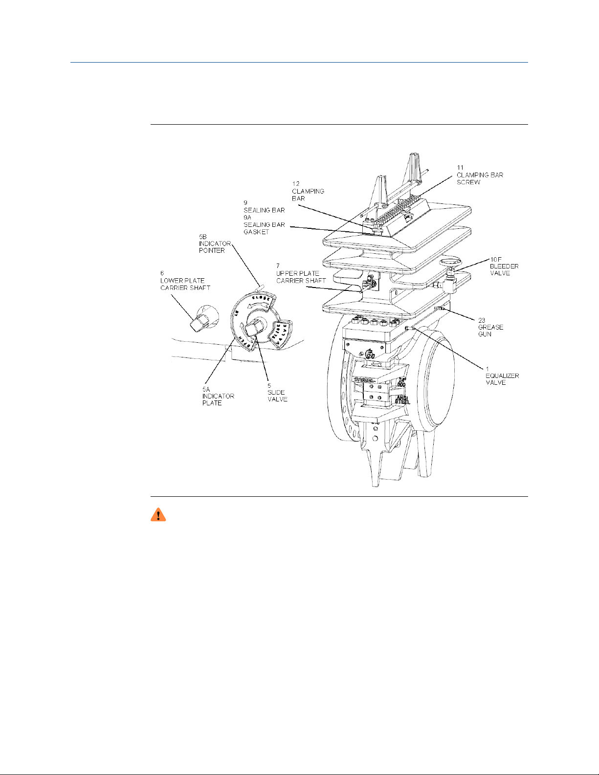
General Information Owner and operator manual
October 2019 P/N 3-9008-001
2.1.1 Information prior to installation
Figure 2-2: Daniel Senior Orifice Fitting component identification
WARNING
HIGH PRESSURE HAZARD
Follow all instructions provided in this section when installing the Sealing Bar Gasket
(9A), Sealing Bar (9), and Clamping Bar (12).
Failure to comply may cause pressurized fluids to escape, resulting in death or serious
injury.
The Daniel Senior Fitting is an essential element in any orifice measurement system. Other
elements in an orifice measurement system may include a meter tube, a flow conditioner,
and various data recording devices.
Purchasers have the option of acquiring only a Daniel Senior fitting unit for later
installation in a flow measurement system, purchasing a Senior Orifice fitting with a meter
tube, or purchasing a complete flow measurement system containing a Senior Orifice
fitting.
54 Senior Orifice Fitting
Page 55

Owner and operator manual General Information
P/N 3-9008-001 October 2019
At our factories, Emerson personnel perform two unique tests on each Senior fitting for
fluid retention. The first test is an internal hydrostatic SHELL test on a full assembled TOP
(14) and BODY (4) with the slide valve seat (18) open, to a minimum pressure of 1.5 times
its rated maximum allowable operating pressure. The second test is an internal hydrostatic
SEAT test. With the slide valve seat (18) closed, Emerson personnel apply a minimum
pressure of 1.1 times the rated maximum allowable operating pressure to the BODY (4)
only.
Important
When purchasing only a Daniel Senior fitting, it is the responsibility of the both the
product owners and product operating personnel to perform an internal hydrostatic shell
test of the final meter tube assembly prior to service.
Product owners and product operating personnel performing an internal hydrostatic SEAT
test of the Daniel Senior fitting prior to service should not exceed 1.1 times its rated
maximum allowable operating pressure within the BODY (4) and with the slide valve seat
(18) closed.
WARNING
FLUID EXPLOSION HAZARD
Never pressurize a unit above the limits recommended in this manual. Before
pressurizing the Daniel Senior Fitting, confirm the maximum allowable operating
pressure (MAOP) of each item in the system.
Over-pressurizing the Daniel Senior fitting could lead to an explosive release of fluid
resulting in death, serious injury or damage to the Senior.
2.1.2
When assembling a flow measurement system that will contain a Daniel Senior Orifice
Fitting, particular attention should be paid to the requirements for permanent joining of
components. This will be to ensure optimal measurement performance and successful
pressure test results. Referencing an appropriate measurement code (API-14.3, ISO 5167,
etc.) will aid in this assembly.
NOTICE
Follow all the safety and equipment limits recommended in Conditions and specifications
of this manual.
It is the owner's and/or purchaser's responsibility to comply with these parameters.
NOTICE
On installations built to comply with the European Union Pressure Equipment Directive
(PED) 2014/68/EU, it is the responsibility of the end user to meet all essential safety
requirements of the directive (available on the internet).
End users must pay particular attention to the requirements for permanent joining and
non- destructive testing. Refer to the "Daniel Orifice Fittings - Installation and Operating
Instructions specific to the Pressure Equipment Directive", Part Number 3-9008-002
(available on the Daniel Flow website).
Storage
Follow your company's storage procedures when placing any measurement equipment
into inventory. Spraying a light coat of rust inhibitor onto the inside bore of a Daniel
Senior, and to the bore of the meter tube, may protect its surface finish during storage.
Owner and operator manual 55
Page 56

General Information Owner and operator manual
October 2019 P/N 3-9008-001
2.1.3 Preliminary Steps
NOTICE
Follow all the safety and equipment limits recommended in Conditions and specifications
of this manual. It is the owner's and/or purchaser's responsibility to comply with these
parameters.
The Senior may arrive at your site in any number of ways, usually as a component in a
meter tube/measurement system, or as a loose fitting. If received as a loose fitting, then
see the appropriate code (API-14.3, etc.) for assembly requirements.
It is the responsibility of the product operators to clean the Senior and all piping
components of foreign matter such as welding debris, scale, oil, grease, and dirt before
commissioning.
Record the serial plate data on the Senior's nameplate for future reference. Always provide
the serial number and model number when ordering spare parts.
The factory places the plate carriers (8DMC or 8DM) inside the fitting for shipment.
The factory packages the Orifice Plates (13) and Seal Ring units (8E-DSC or 8E-DS; 8TSC or
8TS; 8MSC or 8MS; 8SNC or 8SN) separately from the fitting.
2.1.4
2.1.5
Severe service conditions
If product owner expects to encounter gas or liquid composition where there is a
likelihood of sediment accumulation within the fitting, then Emerson recommends that
the owner instruct their operators to remove Drain Valve Plug (30) and install a blow-down
valve in its place.
Corrosive service
Corrosive environments may affect both the external and internal surfaces of the Senior.
External corrosive environments are defined as those conditions that affect the outer
surfaces of the Senior, while an internal corrosive environment is a condition that affects
the surface inside the Senior. Read, understand, and follow instructions in the sections
below if an internal or external corrosive environment exists.
External corrosive environments
For Seniors located in external corrosive environments (offshore platforms, marine
terminals, etc), Emerson recommends replacing the standard carbon steel Equalizer Valve
(Complete) (1), Bleeder Valve (Complete) (10B), Grease Gun (Complete) (23) and Drain
Valve Plug (30) with the stainless steel versions listed in the "Corrosive Service" column
(refer to Low temperature service).
Internal corrosive environments
It is the end user's responsibility to specify a fitting's material of construction based upon
their knowledge of the process fluid and environmental conditions of an intended
application. A number of trim packages are available for severe service to improve
durability of the Senior fitting (Refer to Table 1-3).
56 Senior Orifice Fitting
Page 57

Owner and operator manual General Information
P/N 3-9008-001 October 2019
The inside diameter specifications of a Senior fitting are exact. No allowance is provided
for corrosion of the inside diameter.
2.1.6 Low temperature service
The fitting's material of construction is just one factor to consider when placing an orifice
fitting into a low temperature service. Other factors to consider are the temperature
characteristics of the slide valve lubricant, and the temperature limitations of the orifice
plate seal material.
Operating temperatures have an effect on all valve lubricant Emerson offers. Lower
temperatures increase a valve lubricant's viscosity. Higher viscosity lubricant is more
difficult to transfer from the grease gun, through the grease channels and to the slide
valve. Additionally the application of a high viscosity lubricant into a Daniel fitting may
result in an uneven the distribution of lubricant around the Slide Valve Seat (18). An
uneven distribution of lubricant may allow leakage to occur between the Slide Valve Seat
(18) and the Slide Valve Strip (3) during a plate change operation. Refer to Lubricant
information to help you to select a lubricant for your application.
Orifice plate seal material is another factor to consider when selecting components for low
temperature services. Refer to Conditions and specifications "Orifice plate seal material
temperature limitations" to help you to select an orifice plate seal for your application.
For Seniors located in low temperature environments (atmospheric temperature ranges of
+32° F [0° C] to -20° F [-29° C]), Emerson recommends replacing the standard carbon steel
Equalizer Valve (Complete) (1), Bleeder Valve (Complete) (10B), Grease Gun (Complete)
(23) and Drain Valve Plug (30) with the low temperature versions listed in the "Low Temp
Service" column (refer to Low temperature service).
Table 2-1: Alternate components
Part
number
1 Equalizer
10B Bleeder Valve 2"/14" (complete) 1-504-01-026 1-504-01-040 1-504-01-040
10F Bleeder Valve 16" only
23 Grease Gun Complete 1-504-01-051 1-504-01-050 1-504-01-071
30 Drain Plug 1/2" - 14 NPT 1-507-01-103 1-507-01-143 1-507-01-170
30 Drain Plug 3/4" - 14 NPT 1-507-01-104 1-507-01-144 1-507-01-171
30 Drain Plug 1" - 11.5 NPT 1-507-01-105 1-507-01-145 1-507-01-172
Description Plug size Standard
service
complete 1-504-01-011 1-504-01-004 1-504-01-016
Valve
1-504-01-028 1-504-01-041 1-504-01-041
(complete)
Stainless
steel
corrosive
service
Low
temperature
service
2.1.7 Design considerations
Owners and operators select and place Daniel fittings in a variety of flow measurement
services around the world with successful results. Emerson personnel understand that
each flow measurement service has its own set of unique process and environmental
Owner and operator manual 57
Page 58

General Information Owner and operator manual
October 2019 P/N 3-9008-001
conditions. Although Emerson designs, builds and offers a product line that may be
applicable to most flow measurement services, it is the end user's responsibility to match
the fitting to the service to achieve successful results.
Important
Product owners and operating personnel must evaluate both process fluid and
environmental conditions of an intended service and select the appropriate fitting to
match those service requirements. Once selected, the product owners and operating
personnel must place the Daniel fitting in a well-designed piping system.
Below is a list of some, but not all, pipe design conditions to consider:
• Service operating pressure
• Service testing pressures
• Service process temperature and ambient site temperatures
• Mass of fluid in process and test conditions
• Chemical composition and toxicity of fluid in operating conditions
• Traffic, wind and earthquake at loading site
2.1.8
• Reaction forces and moments (meter position, supports, attachments, piping, etc.)
• Corrosion, erosion, fatigue, etc.
• Decomposition of unstable fluids in operating and test conditions
• Possible damage from external fire
Installation configurations
Up to 12" nominal size (all ANSI Classes)
Product owners and operating personnel may install any Daniel Senior fitting, up to 12inch line size, in one of two configurations. One configuration is to install the fitting in
piping system with product flowing in a horizontal direction (Figure 2-3). The other is to
install the fitting in piping system with product flowing in a vertical direction (Figure 2-4).
Figure 2-3: Horizontal Flow
Installing the fitting in a vertical flow direction (see Figure 2-4) gives a product owner and
operating personnel the option to fix the fitting in any position parallel to the ground.
Although the insertion of the fitting in the vertical flow direction can be vertical UP or
58 Senior Orifice Fitting
Page 59
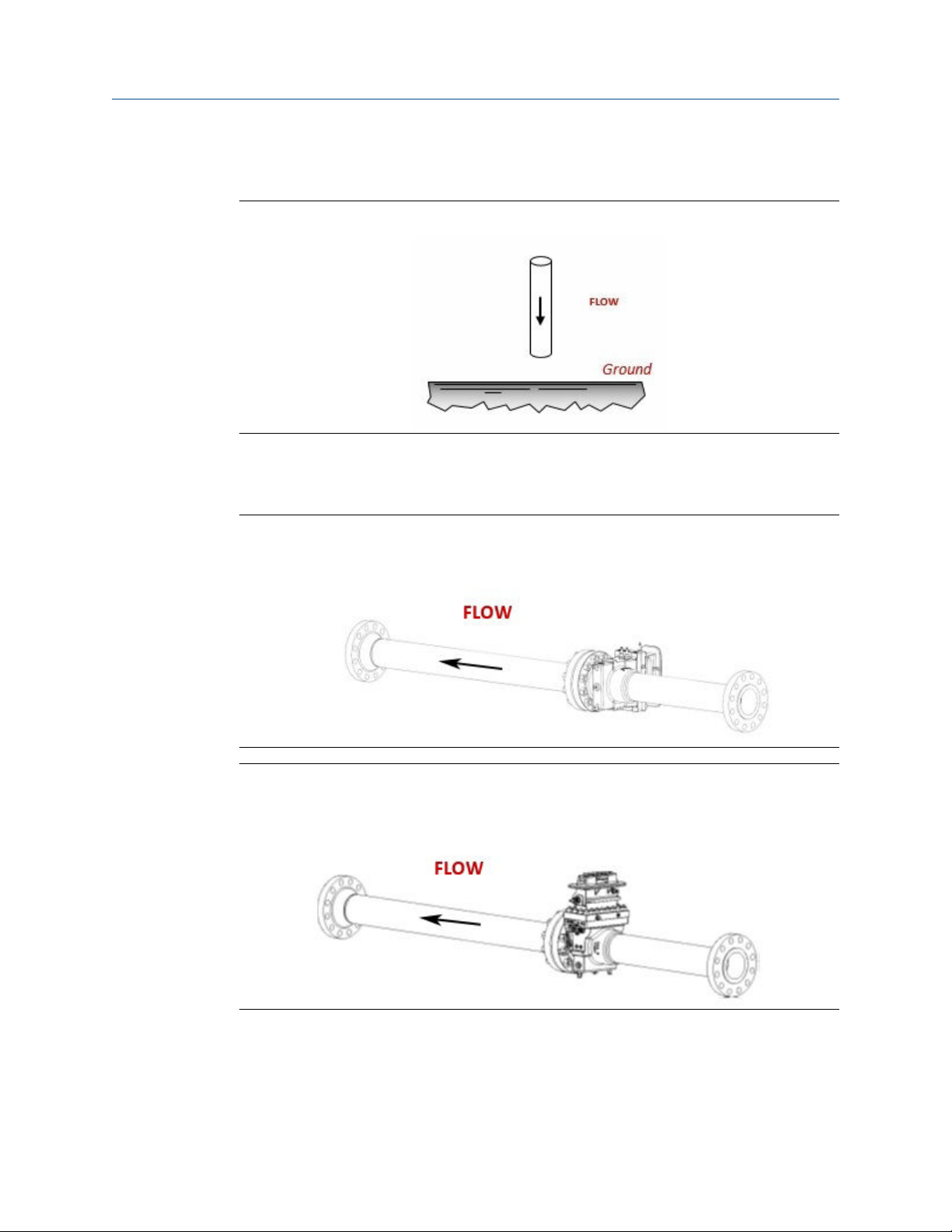
Owner and operator manual General Information
P/N 3-9008-001 October 2019
vertical DOWN, it is recommended the fitting be in the vertical down flow direction to
reduce the potential of debris collecting on the orifice plate.
Figure 2-4: Vertical flow
Installing the fitting in a horizontal flow direction gives a product owner and operating
personnel the option to fix the final position of the fitting parallel (Figure 2-5 or Figure
2-7), or perpendicular (Figure 2-6) to the ground as shown.
Figure 2-5: Parallel to the ground "Right side" position
Figure 2-6: Perpendicular to the ground "Normal" position
Owner and operator manual 59
Page 60

General Information Owner and operator manual
October 2019 P/N 3-9008-001
Figure 2-7: Parallel to the ground "Left side" position
14" and larger nominal size (all ANSI Classes)
14" and larger Senior fittings are recommended to be installed only in Horizontal Flow "Normal Position" direction per Figure 2-6.
60 Senior Orifice Fitting
Page 61

Owner and operator manual Operate
P/N 3-9008-001 October 2019
Part III
Operate
Owner and operator manual 61
Page 62

Operate Owner and operator manual
October 2019 P/N 3-9008-001
62 Senior Orifice Fitting
Page 63

Owner and operator manual Commissioning
P/N 3-9008-001 October 2019
3 Commissioning
3.1 Commission the Daniel Senior Orifice Fitting
DANGER
FLUID EXPLOSION HAZARD
The Senior is a device that contains fluid at elevated pressure.
Failure to follow the instructions in this manual will result in death or serious injury.
Commissioning is the process of verifying that a system performs in accordance with the
user's intended operational, maintenance, and measurement requirements. Emerson
provides the following procedures to guide personnel in verifying that the Senior performs
in accordance with the user's intended requirements.
Pre-Commissioning
Ensure that the following checklist is met prior to commissioning the Senior:
• The internal pressure throughout the Senior is equal to atmospheric pressure (0 psig / 0
barg).
• Confirm that the flow directional indicator (arrow or "INLET"/"OUTLET" tags) positioned
on the Senior Body (4) corresponds with the intended fluid flow direction of the
measurement system.
• Check shipment to verify that the shipping kit contains an Operating Wrench (2),
Grease Gun (23), Indicator Plate (5A-LH marked "LH" for left-hand side operation and
5A-RH marked "RH" for right-hand side operation) and (2 EA) Indicator Pointer (5B).
• Confirm the proper operating clearance around the Senior per information contained
in the Daniel technical guide "DAN-DIF-TG-11-1003".
• Check accessibility and Operating Wrench (2) clearance at the following Senior
locations:
1. Lower Plate Carrier Shaft (6)
2. Upper Plate Carrier Shaft (7)
3. Bleeder Valve ()
4. Equalizer Valve (1)
5. Slide Valve Shaft (5)
• Confirm the Operating Wrench (2) operational clearances for the Plate Carrier (8DM or
8DMC) extraction, and meter tap equipment draw clearance.
• Install the Grease Gun(s) (23) into holes in the base of the Top (14) as stated below:
— Remove the plastic shipping plugs
— Put thread sealer on the end threads of the Grease Gun Body (23) and tighten
securely. Check the accessibility to the Grease Gun(s) (23) after installation.
— Adjust the Senior's position if required.
Owner and operator manual 63
Page 64

Commissioning Owner and operator manual
October 2019 P/N 3-9008-001
• Install the Indicator Pointer (5B) on to the Body (4) by tapping the two drive screws into
the holes located above the Slide Valve Shaft (5).
• Install the Indicator Plates (5A-LH and 5A-RH) on the Slide Valve Shaft (5), directly
below the Indicator Pointer (5B).
• Orient the Indicator Plate (5A-LH and 5A-RH), as stated below, depending on the shaft's
left or right side location (The right hand and left hand Indicator Plates (5A-LH and 5ARH) are different and not interchangeable):
— Shaft on the left hand side facing with the flow (standard LH position): when the
shaft is rotated clockwise until it stops, the Indicator Plate (5A-LH) word OPEN
should appear below the Indicator Pointer (5B). Install the Indicator Plate (5A-LH)
on the shaft in this position and tighten the Set Screw (10G) securely.
— Shaft on the right hand side facing with the flow (standard RH position): When the
shaft is rotated counterclockwise until it stops, the Indicator Plate (5A-RH) word
OPEN should appear below the Indicator Pointer (5B). Install the Indicator Plate (5ARH) on the shaft in this position and tighten the Set Screw (10G) securely.
— After installation, rotate the Slide Valve Shaft (5) until it stops. The word CLOSED on
both Indicator Plates (5A-LH and 5A-RH) should appear below the Indicator Pointer
(5B).
• Plate Carrier shipment verification
The Seniors leave the factory with the Plate Carriers (8DM or 8DMC) in the Body (4) to
prevent the damage of the Plate Carrier (8DM or 8DMC) or the slide valve assembly
during transit. Whether or not the Senior arrives directly from the factory, installation
personnel must remove the Clamping bar and open the Top (14) and the Slide Valve
Shaft (5) to ensure that the Plate Carrier (8DM or 8DMC) is inside. The Plate Carrier
(8DM or 8DMC) should be removed before performing any tests.
• Orifice plates and Seal Rings verification
The factory packages the Orifice Plates (13) and Seal Rings units (8E-DSC or 8E-DS;
8TSC or 8TS; 8MSC or 8MS; 8SNC or 8SN) separate from the fitting.
• With the slide valve in the fully opened position, follow these instructions:
— Rotate the Lower Plate Carrier Shaft (6) first.
— Rotate the Upper Plate Carrier Shaft (7) to remove the Plate Carrier (8DM or 8DMC).
— Put the Plate Carrier (8DM or 8DMC) in a safe, protected area for use later in the
installation process.
— Replace the Sealing Bar (9 or 9HP), the Sealing Bar Gasket (9A, 9AHP or 9CF) and
the Clamping Bar (12 or 12HP)
— Tighten and secure all Clamping Bar Screws (11) per the information and
procedures contained in Torque information
CAUTION
LOOSE CLAMPING BAR SCREW HAZARD
The factory assembled and shipped this product with loose clamping bar screws.
Tighten all Clamping Bar Screws(11) per the information and procedures contained in
Torque information before applying pressure to this product.
Failure to comply may result in death, serious injury or equipment damage.
64 Senior Orifice Fitting
Page 65

Owner and operator manual Commissioning
P/N 3-9008-001 October 2019
3.2 Commission the line pressure test
After installing the Daniel Senior Orifice Fitting, personnel must perform a pressure test for
the service line that includes, but is not limited to, the meter tube and Senior.
Commissioning line pressure test start checklist:
• The internal pressure throughout the Senior is equivalent to atmospheric pressure (0
psig / 0 barg).
• The Slide Valve Shaft (5) must be in the "OPEN" position.
• The Equalizer Valve (1) must be in the "OPEN" position.
• The Bleeder Valve (10B10F) must be in the "CLOSED" position.
• Orifice Plate Carrier (8DM) is installed in the Senior Body (4).
• The Orifice Plate (13) and Orifice Plate Sealing Unit (8E-DS or 8TS or 8MS or 8SN) is not
installed on the Orifice Plate Carrier (8DM).
• The Sealing Bar Gasket (9A) and Sealing Bar (9) are installed.
• The Clamping Bar (12) is installed.
• All Clamping Bar Screws (11) are tightened and secured per the information and
procedures contained in Torque information
WARNING
FLUID EXPLOSION HAZARD
Never pressurize a unit above the limits recommended in this manual. Before
pressurizing the Daniel Senior Fitting, confirm the maximum allowable operating
pressure (MAOP) of each item in the system.
Over-pressurizing the Daniel Senior fitting could lead to an explosive release of fluid
resulting in death, serious injury or damage to the Senior.
Procedure
1. Install a pressure gauge in a location on the Senior or the piping system that will
indicate the pressure contained in the Fitting. The gauge should have a maximum
pressure rating slightly above the maximum pressure to be applied during the test.
Important
Emerson hydrostatically tests every Senior unit for fluid retention, under factory
controlled conditions , to a minimum pressure of 1.5 times its rated maximum
allowable operating pressure. If purchased alone, without a meter tube, any
hydrostatic testing of the meter tube assembly is the responsibility of the product
owners or product operating personnel.
2. Slowly pressurize the system containing the Senior at a rate of 1 psig per second
(0.07 bars per second) until the pressure inside the Senior reaches 20 psig (1.4 barg)
then stop and hold pressure for five minutes.
Owner and operator manual 65
Page 66

Commissioning Owner and operator manual
October 2019 P/N 3-9008-001
Important
During the five-minute hold period, apply a leak detection solution to all joint and
connector areas of the Senior and line connections. No leakage should be visibly
detectable or audibly detectable during the hold period.
3. If a leak is detected, mark the leak area with a marker and reduce the pressure
inside the Senior to 0 psig (0 barg). Tighten any fastener or connector adjacent to
the leak area and repeat the leak test again.
4. If after several attempts to contain the leakage, the leakage persists, call Flow
Lifecycle Services for Daniel products for assistance. Contact information is found in
the back of this manual.
5. Once the 20 psig (1.4 barg) leak test is complete, and no leaks are detected, slowly
raise the pressure inside the Senior at a rate of 10 psig per second (0.7 barg per
second) to the maximum operating pressure of the lowest rated item in the system.
However, it should not to exceed 1.5 times the noted rated working pressure of the
Senior. Hold the maximum operating pressure on the system for a period of ten
minutes.
Important
During the ten-minute hold period, apply a leak detection solution to all joint and
connector areas of the Senior and line connections. No leakage should be visibly
detectable or audibly detectable during the hold period.
6. If a leak is detected, mark the leak area with a marker and reduce the pressure
inside the Senior to 0 psig (0 barg). Tighten any fastener or connector adjacent to
the leak area and repeat the leak test again.
7. If after several attempts to contain the leakage, the leakage persists, call Flow
Lifecycle Services for Daniel products for assistance.
WARNING
PRESSURIZED FLUID HAZARD
When opening the bleeder valve (10B) or venting the Top (14) through the
bleeder valve (10B), direct the released pressurized fluid away from any individual
in accordance with local environment regulations to a safe area.
The bleeder valve (10B) releases pressurized fluid that may cause contamination
and/or accumulation of volatile gas mixtures. Failure to comply may cause death
or serious injury.
8. Slowly release the pressure from the Senior until the pressure gauge reads zero (0)
psig by venting the Top (14) through the bleeder valve (10B).
9. Close the slide valve by rotating the Slide Valve Shaft (5). Close the Equalizer Valve
(1). Open the Bleeder Valve (10B).
Steps 10 and 11 are for the Seniors equipped with lubricated slide valves only. For
Soft Seat equipped Seniors, skip these steps.
10. Once the valves are in position as described in Step 9, remove the stem from the
Grease Gun (23) and insert a lubricant stick into the Grease Gun (23).
66 Senior Orifice Fitting
Page 67

Owner and operator manual Commissioning
P/N 3-9008-001 October 2019
WARNING
PRESSURIZED FLUID HAZARD
Using the Grease Gun (23), inject grease into the slide valve seat channels at a
rate of 4 to 6 turns per minute and only under the following conditions:
• Bleeder Valve is open.
• Sealing bar/Clamping bar is in place and tight.
Injection of the grease at a faster rate will lead to the separation of the valve strip
from the valve seat, resulting in release of pressurized fluid which may cause
death or serious injury.
11. Return the stem to the Grease Gun (23) and begin turning the stem by hand into
the Grease Gun (23) until resistance is felt.
3.3 Orifice Plate Installation
After completion of the commissioning line pressure test in Commission the line pressure
test, install and lower the Plate Carrier (8DM or 8DMC) and Orifice Plate Assembly (13) into
the Body (4) to begin measurement operations.
WARNING
EXPLOSION HAZARD
Ensure that the Daniel Senior Orifice Fitting is at atmospheric pressure.
Performing the Orifice Plate (13) installation with the Senior above atmospheric
pressure may lead to an explosive release resulting in death or serious injury.
Orifice Plate (13) installation start checklist:
• Senior is at atmospheric pressure .
• The Slide Valve Shaft (5) must be in the "OPEN" position
• The Equalizer Valve (1) must be in the "OPEN" position
• The Bleeder Valve (10B) must be in the "OPEN" position
Procedure
1. Remove the Clamping Bar (12 or 12HP) by loosening all the Clamping Bar Screws
(11), two turns maximum, and by sliding the bar from the slot.
2. Remove the Sealing Bar (9 or 9HP) and the Sealing Bar Gasket (9A, 9A-HP or 9CF).
3. The three basic components of all Daniel Plate Carrier (8DM or 8DMC) assemblies
are:
• Plate Carrier (8DM or 8DMC)
• Orifice Plate Seal Ring (8E-DS/8E-DSC, 8TS/8TSC, 8E-DVS, 8SN/8SNC, or 8MS/
8MSC)
• Orifice Plate (13)
a) Assemble the Orifice Plate (13), with the appropriate seal ring, into the Plate
Carrier (8DM or 8DMC). If a DSC or DSDVS seal is used, lubricate both seal
Owner and operator manual 67
Page 68
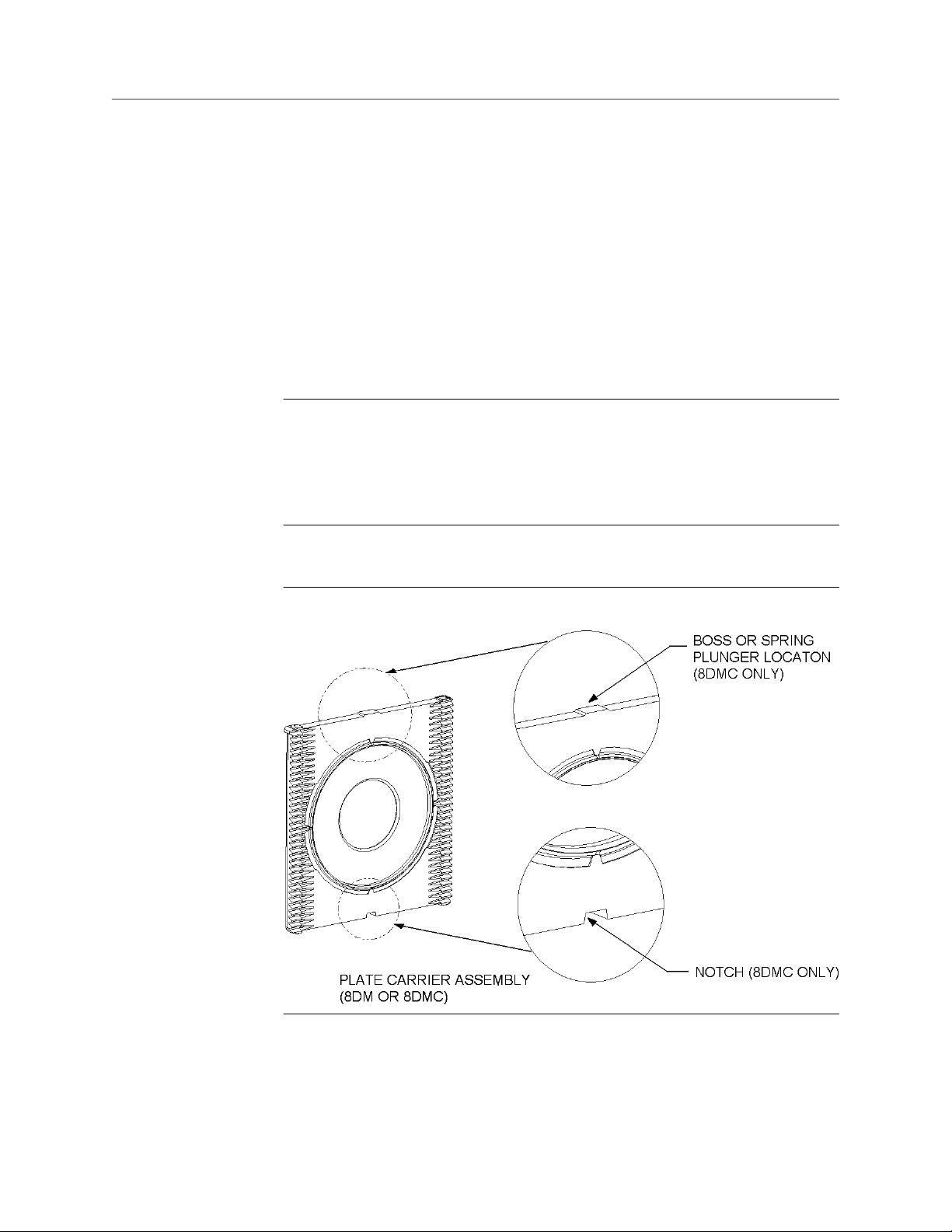
Commissioning Owner and operator manual
October 2019 P/N 3-9008-001
faces with a safe-for- service light oil or grease. Refer to "Senior Orifice Fitting
Technical Guide: DAN-DIF-TG-11-1003".
All 2"-8" Daniel Senior Orifice Fitting Plate Carriers (8DMC) designed for API-14.3
have two important features that will help field technicians properly align it prior to
installation. The first feature is a NOTCH, and the second feature is a BOSS or
SPRING PLUNGER. (Refer to Orifice Plate Installation).
a) In order to ensure correct measurement and to optimize metering
performance, field service technicians must properly install the 2"-8" Plate
Carrier (8DMC) assembly into the Senior.
4. Orient the 2"-8" Plate Carrier (8DMC) assembly with the notch down. The notch end
of the 2"-8" Plate Carrier (8DMC) assembly must enter the Senior first.
Important
Install the Plate Carrier (8DM) assembly into the Senior with the gear rack facing
downstream (refer to (#unique_43/unique_43_Connect_42_fig_vsz_dzp_jdb) and
(Figure 3-2)).
Failure to align and install Plate Carrier (8DM) assembly as instructed will cause
erroneous measurement results.
5. Align the plate carrier gear rack teeth to the Plate Carrier (8DM or 8DMC) shaft
pinion on the Senior when installing the Plate Carrier (8DM or 8DMC) assembly.
Figure 3-1: Plate carrier (8DM or 8DMC) plunger and notch location
The diagram below depicts the proper orientation of the Plate Carrier (8DM or
8DMC) assembly prior to lowering it into the measurement position in the Senior.
68 Senior Orifice Fitting
Page 69
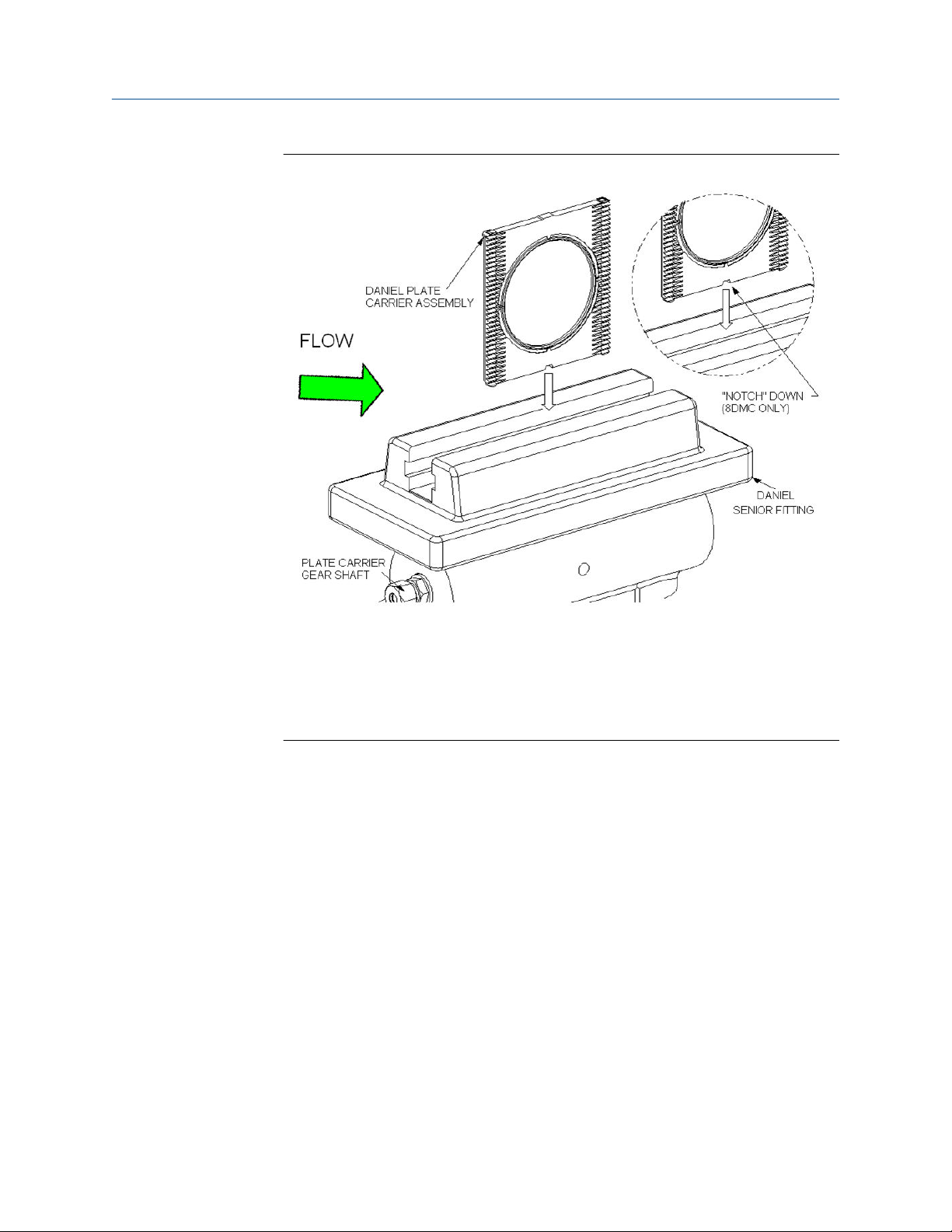
Owner and operator manual Commissioning
P/N 3-9008-001 October 2019
Figure 3-2: Orientation of plate carrier (8DM or 8DMC) prior to installation
NOTES:
• The gear rack side of the Plate Carrier (8DM or 8DMC) assembly must face the
downstream direction of flow.
• If the Orifice Plate (13) bore has a bevel, the bevel shall face the downstream
direction of flow.
6. Rotate the Upper Plate Carrier Shaft (7) a minimum of 1/4 turns OPPOSITE of the
direction used to lower the Plate Carrier (8DM or 8DMC) assembly. This will allow it
to "align" itself with the Top (14) shaft gear teeth.
7. Once the Plate Carrier (8DM or 8DMC) assembly is aligned, rotate the Upper Plate
Carrier Shaft (7) in the direction to lower it from the Top (14) to the Body (4).
8. Once the Plate Carrier (8DM or 8DMC) assembly is clear of the Upper Plate Carrier
Shaft (7), rotate the Lower Plate Carrier Shaft (6) until the Plate Carrier (8DM or
8DMC) assembly is completely inserted into the Body (4).
9. Install the Sealing Bar (9 or 9HP), the Sealing Bar Gasket (9A, 9A-HP or 9CF), and the
Clamping Bar (12 or 12HP) in position on the Top (14) and tighten the Clamping Bar
Screws (11). Refer to Torque information for torque values.
Owner and operator manual 69
Page 70

Commissioning Owner and operator manual
October 2019 P/N 3-9008-001
CAUTION
LOOSE CLAMPING BAR SCREW HAZARD
The factory assembled and shipped this product with loose clamping bar screws.
Tighten all Clamping Bar Screws(11) per the information and procedures
contained in Torque information before applying pressure to this product.
Failure to comply may result in death, serious injury or equipment damage.
10. Rotate the Slide Valve Shaft (5) to the CLOSED position. This closes the slide valve,
separating the Body (4) from the Top (14).
Steps 11 and 12 are for Seniors equipped with lubricated slide valves only. For Soft
Seat equipped Seniors, skip to step 13.
11. Once the Slide Valve Shaft (5) is in the CLOSED position, remove the stem from the
Grease Gun (23) and insert a lubricant stick (Refer to Lubricant information) into the
Grease Gun (23).
WARNING
PRESSURIZED FLUID HAZARD
Using the Grease Gun (23), inject grease into the slide valve seat channels at a
rate of 4 to 6 turns per minute and only under the following conditions:
• Bleeder Valve is open.
• Sealing bar/Clamping bar is in place and tight.
Injection of the grease at a faster rate will lead to the separation of the valve strip
from the valve seat, resulting in release of pressurized fluid which may cause
death or serious injury.
12. Return the stem to the Grease Gun (23) and begin turning the stem by hand into
the Grease Gun (23) until resistance is felt. Once resistance is felt, use the supplied
Daniel Operating Wrench (2) to continue to turn the stem at a rate of 4 to 6 turns
per minute.
13. Close both the Equalizer (1) and the Bleeder Valves (10B).
14. Remove any commissioning equipment (flanges, tubing, etc.) from the system.
The Senior is now ready for final pressurization and operation.
70 Senior Orifice Fitting
Page 71

Owner and operator manual Maintain
P/N 3-9008-001 October 2019
Part IV
Maintain
Owner and operator manual 71
Page 72

Maintain Owner and operator manual
October 2019 P/N 3-9008-001
72 Senior Orifice Fitting
Page 73

Owner and operator manual Normal operation conditions
P/N 3-9008-001 October 2019
4 Normal operation conditions
4.1 Maintenance
4.1.1 Recommendations for lubrication
Under normal measurement conditions, Emerson recommends lubricating the slide valve
and exercising several key components of the Daniel Senior Orifice Fitting every thirty days
(Refer to Component exercise). If the plate changing operations are performed within this
period, omit this operation.
4.1.2
Lubrication
Important
The information in this section, Lubrication, DOES NOT apply to Seniors equipped with
Soft Seat slide valves.
In order to perform the maintenance operation described in this section, the following
maintenance check list must be met first:
• The slide valve must be in the "CLOSED" position.
WARNING
PRESSURIZED FLUID HAZARD
When opening the bleeder valve (10B) or venting the Top (14) through the bleeder
valve (10B), direct the released pressurized fluid away from any individual in accordance
with local environment regulations to a safe area.
The bleeder valve (10B) releases pressurized fluid that may cause contamination and/or
accumulation of volatile gas mixtures. Failure to comply may cause death or serious
injury.
• The Bleeder Valve (10B) must be in the "OPEN" position.
• The Equalizer Valve (1) must be in the "CLOSED" position.
• The Senior must contain 100 psig minimum line pressure.
Procedure
1. Remove the stem from the Grease Gun (23) and insert a lubricant stick into the
Grease Gun (23).
Owner and operator manual 73
Page 74

Normal operation conditions Owner and operator manual
October 2019 P/N 3-9008-001
Figure 4-1: Step 1
Figure 4-2: Step 1A
74 Senior Orifice Fitting
Page 75
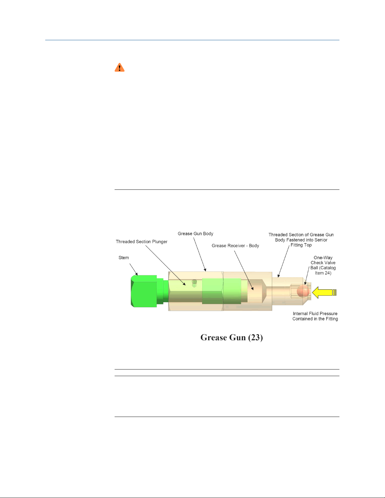
Owner and operator manual Normal operation conditions
P/N 3-9008-001 October 2019
WARNING
PRESSURIZED FLUID HAZARD
Using the Grease Gun (23), inject grease into the slide valve seat channels at a
rate of 4 to 6 turns per minute and only under the following conditions:
• Bleeder Valve is open.
• Sealing bar/Clamping bar is in place and tight.
Injection of the grease at a faster rate will lead to the separation of the valve strip
from the valve seat, resulting in release of pressurized fluid which may cause
death or serious injury.
2. Return the stem to the Grease Gun (23) and begin turning it clockwise by hand into
the Grease Gun (23) until resistance is felt. Once this is done, use the supplied
Operating Wrench (2) to continue to turn the stem at a rate of 4 to 6 turns per
minute.
Figure 4-3: Step 2
Important
By turning the stem of the Grease Gun (23) at a rate of 4 to 6 turns per minute, the
lubricant is forced through the Slide Valve Seat (18) channels at a rate that allows
the lubricant to travel freely, yet not separate the valve strip from the valve seat.
This method will keep fresh grease in the lubrication passages.
3. Close Bleeder Valve (10B).
Owner and operator manual 75
Page 76

Normal operation conditions Owner and operator manual
October 2019 P/N 3-9008-001
4.1.3 Component exercise
Prerequisites
In order to perform the maintenance operation described in this section, the following
component exercise start check list must be met:
• The slide valve must be in the "CLOSED" position,
• The Bleeder Valve (10B) must be in the "CLOSED" position.
• The Equalizer Valve (1) must be in the "OPEN" position.
At this point the fluid pressure in the Top (14) will equal the fluid pressure in the Body (4).
Procedure
1. If the differential pressure is greater than 200 inches of H O, reduce the differential
pressure across the meter to a maximum of (200 inches of H O) 7.2 psig.
2. Rotate the Upper Plate Carrier Shaft (7) located in the Top (14) several times in both
directions. The Shaft (7) should turn freely.
3. Rotate the Slide Valve Shaft (5) in one direction until it stops. Then rotate the Slide
Valve Shaft (5) in the opposite direction until it stops. Repeat this sequence several
times. The slide valve should travel freely in both directions with light resistance.
Leave the slide valve in the OPEN position.
Important
The following operation will affect the flowing differential and will be shown on any
chart or instrument, keep records of differential, unless these instruments are
isolated.
4. Rotate the Lower Plate Carrier Shaft (6), located in the Body (4), one turn to raise
the Plate Carrier (8DM or 8DMC).
5. Rotate the Lower Plate Carrier Shaft (6) one turn in the opposite direction to lower
the Plate Carrier (8DM or 8DMC).
This operation raises and lowers the Plate Carrier (8DM or 8DMC) in and out of the
flow stream. An initially high resistance to turning will be encountered when the
Orifice plate (13) seal (see "Senior Orifice Fitting Technical Guide: DAN-DIFTG-11-1003") is loosened from the Senior seal surface. Resistance to turning will
also be present when the Plate Carrier (8DM or 8DMC) is lowered into its
measurement position again.
6. Return the Plate Carrier (8DM or 8DMC) to the fully seated position in the Body (4).
7. Close the slide valve and close the Equalizer Valve (1).
76 Senior Orifice Fitting
Page 77

Owner and operator manual Normal operation conditions
P/N 3-9008-001 October 2019
WARNING
PRESSURIZED FLUID HAZARD
When opening the bleeder valve (10B) or venting the Top (14) through the
bleeder valve (10B), direct the released pressurized fluid away from any individual
in accordance with local environment regulations to a safe area.
The bleeder valve (10B) releases pressurized fluid that may cause contamination
and/or accumulation of volatile gas mixtures. Failure to comply may cause death
or serious injury.
8. Open the Bleeder Valve (10B) to vent the Top (14).
Steps 9 and 10 are ONLY required for the Seniors equipped with grease assisted,
metal-to-metal slide valves. Personnel operating the Seniors equipped with O-ring
seal "soft seat" design slide valves, skip to step 11.
9. Remove the stem from the Grease Gun (23) with the Operating Wrench (2) and
insert a lubricant stick into the Grease Gun (23).
WARNING
PRESSURIZED FLUID HAZARD
Using the Grease Gun (23), inject grease into the slide valve seat channels at a
rate of 4 to 6 turns per minute and only under the following conditions:
• Bleeder Valve is open.
• Sealing bar/Clamping bar is in place and tight.
Injection of the grease at a faster rate will lead to the separation of the valve strip
from the valve seat, resulting in release of pressurized fluid which may cause
death or serious injury.
10. Return the stem to the Grease Gun (23) and begin turning the stem by hand into
the Grease Gun (23) until resistance is felt. When resistance is felt, apply the
Operating Wrench (2) to the Grease Gun (23) and continue to turn the stem into
the Grease Gun (23) at a rate of 4 to 6 turns per minute until a seal is achieved.
Important
By turning the stem of the Grease Gun (23) at a rate of 4 to 6 turns per minute, the
lubricant is forced through the Slide Valve Seat (18) channels at a rate that allows
the lubricant to travel freely, yet not separate the valve strip from the valve seat.
This method will keep fresh grease in the lubrication passages.
If the addition of grease does not reduce the flow from the open Bleeder Valve
(10B) to zero, follow these steps:
• Close the Bleeder Valve (10B),
• Open the Equalizer Valve (1), and move the Slide Valve Shaft (5) from the
CLOSED to the OPEN position, and back to the CLOSED position, repeating this
action several times.
• Return the Slide Valve Shaft (5) back to the CLOSED position.
• Close the Equalizer Valve (1) and repeat the lubrication process.
• Open the Bleeder Valve (10B).
Owner and operator manual 77
Page 78

Normal operation conditions Owner and operator manual
October 2019 P/N 3-9008-001
If leakage is still present, close the Bleeder Valve (10B) and leave the Slide Valve
Shaft (5) in the CLOSED position and schedule maintenance on the Senior.
11. Close the Bleeder Valve (10B).
If at any point during the exercise of the components, the resistance encountered
when turning a shaft is greater than the torque applied by hand using the Wrench
(2), further inspection of the Senior is required.
4.2 Orifice plate installation and removal instructions
4.2.1 Plate change procedure overview
Follow these instructions during every plate change.
DANGER
FLUID EXPLOSION HAZARD
Follow the instructions below to avoid inadvertent or accidental opening of the slide
valve and the propulsion of fluid or internal components from the Top (14).
Failure to comply will result in death or serious injury.
Never place any part of your body over the plate carrier slot opening (refer to Figure 4-4) of
the Top (14) when the Sealing Bar Gasket (9A, 9A -HP or 9CF), the Sealing Bar (9 or 9HP)
and the Clamping Bar (12 or 12HP) are removed from the Daniel Senior Orifice Fitting and
the line is under pressure.
Never place the Operating Wrench (2) on the Slide Valve Shaft (5) (refer to Figure 4-5)
when the Sealing Bar Gasket (9A, 9A-HP or 9CF), the Sealing Bar (9 or 9HP) and the
Clamping Bar (12 or 12HP) are removed from the Senior and the line is under pressure.
78 Senior Orifice Fitting
Page 79

Owner and operator manual Normal operation conditions
P/N 3-9008-001 October 2019
Figure 4-4: Top (14) KEEP OUT ZONE
(7)
(7) Daniel Senior Orifice Fitting shown in vertical position. The KEEP OUT ZONE includes the plate carrier slot opening of the
Top (14) even when the Senior is positioned horizontally (laying on its side).
Owner and operator manual 79
Page 80
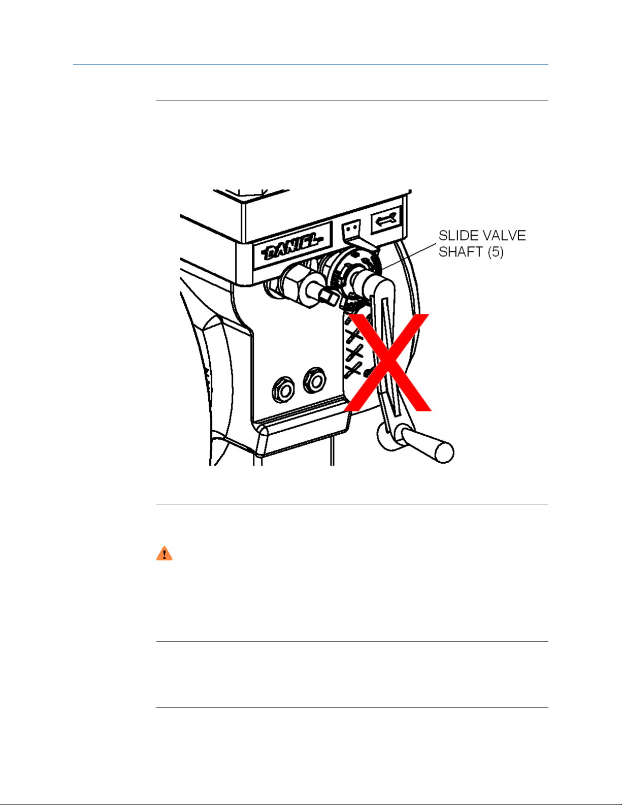
Normal operation conditions Owner and operator manual
October 2019 P/N 3-9008-001
Figure 4-5: Improper Location of Operating Wrench (2) During an Orifice Plate
Change Operation
4.2.2 Selecting an appropriate plate change procedure
WARNING
EXPLOSION HAZARD
The Daniel Senior Orifice Fitting contains fluid at elevated pressure. Ensure to follow the
instructions below for proper installation and removal of the plate.
Failure to comply can cause an explosive release and may result in death or serious
injury.
Important
In order to perform a safe and efficient plate change operation with a Senior, the on-site
personnel must evaluate both the service and environmental conditions prior to beginning
this operation. These conditions may have a dramatic effect on the time required for an
operator's ability to return the Senior to its measurement condition.
80 Senior Orifice Fitting
Page 81

Owner and operator manual Normal operation conditions
P/N 3-9008-001 October 2019
As stated in the product description section of this manual, the Seniors utilize a "dual
chamber" design. A slide valve contains the line pressure in the Body (4) during the plate
extraction from the Senior and plate installation into the Senior. Emerson offers both an ORing seal "softseat" slide valve design, and a grease assisted, metal-to-metal slide valve
design. Both designs ensure the optimum seal performance during this stage in the Orifice
Plate (13) change. Under some service conditions, the grease used in the metal-to-metal
slide valve design may migrate into the Top (14). If this was to occur, then the grease
assisted metal-to-metal slide valve may not perform optimally and leakage will occur.
There are some services where, based on the characteristics of the fluid within and an
intimate knowledge of the system, an operator and owner may allow some leakage past
the slide valve during a plate change operation. This decision to allow leakage should be
made on a case by case basis and be properly documented, communicated to, and
acknowledged by, all personnel involved in the plate change operation. The sole
responsibility for a decision to allow leakage lies with both the product owner and product
operator. Emerson recommends that owners and operators use either the "Quick Change"
or "Extended Time" methods described in this section.
Therefore, when performing an Orifice Plate (13) change on a Senior equipped with a
grease assisted, metal-to-metal slide valve, Emerson recommends that at no time shall an
operator leave the Sealing Bar (9 or 9HP), the Sealing Bar Gasket (9A, 9A-HP or 9CF), and
the Clamping Bar (12 or 12HP) unfastened from the Top (14) except to remove and
replace the Orifice Plate Carrier (8DM or 8DMC) from the Senior.
Finally, the operator should never leave any Senior, O-ring seal "soft-seat" slide valve
design, or a grease assisted, metal-to-metal slide valve design, unattended while the
Sealing Bar (9 or 9HP), the Sealing Bar Gasket (9A, 9A-HP or 9CF), and the Clamping Bar
(12 or 12HP) are unfastened and removed from the Top (14).
In order to assist the operator in determining the safest and most efficient means to
perform the Orifice Plate (13) change on a Senior equipped with a grease assisted slide
valve, Emerson prepared two plate change procedures that an operator may select from.
The operator must select the appropriate procedure based upon their intimate knowledge
of both the service and environmental conditions of that particular flow measurement
system. The two Orifice Plate (13) change procedures described below are the "Quick
Change" process, and the "Extended Time" process. If the Senior is equipped with a "softseat" slide valve design, then the operator may use either procedure.
An operator can select the "Quick Change" process, based upon their determination that it
will take LESS THAN 15 MINUTES from the time the Top (14) fluid is evacuated to the full
replacement of the Clamping Bar (12 or 12HP), the Sealing Bar (9 or 9HP), and the Sealing
Bar Gasket (9A, 9A-HP or 9CF) after the plate change.
The "Extended Time" process is a procedure selected when the operator determines that
the time beginning with the evacuation of Top (14) fluid to the full replacement of the
Clamping Bar (12 or 12HP), the Sealing Bar (9 or 9HP), and the Sealing Bar Gasket (9A, 9AHP or 9CF) after plate change is GREATER THAN 15 MINUTES.
If the operator does not know the time required to perform the Orifice Plate (13) change
operation, then the operator must use the "Extended Time" procedure. The table below
describes the conditions along with the suitable procedure.
Owner and operator manual 81
Page 82

Normal operation conditions Owner and operator manual
October 2019 P/N 3-9008-001
Table 4-1: Plate change procedure selection for grease assisted slide valves and soft
seat slide valves
Operator's evaluation of plate
change conditions
The estimated time period
from the Top (14) fluid
evacuation to the full
replacement of the Clamping
Bar (12 or 12HP), the Sealing
Bar (9 or 9HP), and the Sealing
Bar Gasket (9A, 9A-HP or 9CF)
after plate change is: LESS
THAN 15 MINUTES
The estimated time period
from the Top (14) fluid
evacuation to the full
replacement of the Clamping
Bar (12 or 12HP), the Sealing
Bar (9 or 9HP), and the Sealing
Bar Gasket (9A, 9A-HP or 9CF)
after plate change is: GREATER
THAN 15 MINUTES
The estimated time period
from the Top (14) fluid
evacuation to the full
replacement of the Clamping
Bar (12 or 12HP), the Sealing
Bar (9 or 9HP), and the Sealing
Bar Gasket (9A, 9A-HP or 9CF)
after plate change is:
UNKNOWN
Procedure Type of valve
"Quick Change" Grease assisted slide valve or
Soft seat slide valve
"Extended Time" Grease assisted slide valve or
Soft seat slide valve
"Extended Time" Grease assisted slide valve or
Soft seat slide valve
4.2.3 Orifice plate change operation
Important
In order to perform a safe and efficient plate change operation with a Senior, the on-site
personnel must evaluate both the service and environmental conditions prior to beginning
this operation. These conditions may have a dramatic effect on the time required for an
operator's ability to return the Senior to its measurement condition.
The Daniel Senior Orifice Fitting's Top (14) is designed to temporarily hold the Plate Carrier
(8DM) during plate change operations.
An operator controlled, grease assisted, slide valve separates the Top (14) from the line
pressure to ensure optimum sealing performance. The slide valve grease used to achieve
this performance may migrate into the Top (14) during the plate change operation. If this
was to occur, the slide valve may not perform optimally and may leak.
The grease migration process is both time and environmental condition dependent.
Therefore, Emerson offers two plate change procedures that an operator may choose
from in order to perform this process in the safest and most efficient manner. These
procedures are the "Quick Change" process and the "Extended Time" process.
82 Senior Orifice Fitting
Page 83

Owner and operator manual Normal operation conditions
P/N 3-9008-001 October 2019
The "Quick Change" process is a procedure based upon the operator's knowledge that the
entire Orifice Plate (13) removal and installment, the time spent from the Top (14) fluid
evacuation to the full replacement of the Clamping Bar (12 or 12HP), the Sealing Bar (9 or
9HP), and the Sealing Bar Gasket (9A, 9A-HP or 9CF) is under fifteen (15) minutes. The
"Extended Time" process is a procedure based upon the operator's knowledge that the
entire Orifice Plate (13) removal and installment, the time spent from the Top (14) fluid
evacuation to the full replacement of the Clamping Bar (12 or 12HP), the Sealing Bar (9 or
9HP), and the Sealing Bar Gasket (9A, 9A-HP or 9CF) is over fifteen (15) minutes.
The procedural differences between these two processes are that, once the Plate Carrier
(8DM) is extracted from the Senior, the "Extended Time" process requires the operator to
place a new Sealing Bar Gasket (9A, 9A-HP or 9CF) along with replacing the Sealing Bar (9
or 9HP)/Clamping Bar (12 or 12HP) on the Top (14). Additionally, the operator is required
to add grease to the Senior prior to removing the Sealing Bar (9 or 9HP)/Clamping Bar (12
or 12HP) in order to reinsert the Plate Carrier (8DM) assembly.
For "Soft Seat" equipped Seniors the operator may use either the "Quick Change" or the
"Extended Time" plate removal procedures based upon the immediate service and
environmental conditions encountered.
Emerson recommends either the "Quick Change" or the "Extended Time" plate orientation
process for users of Seniors equipped with lubricated slide valves. Both the "Quick Change"
and the "Extended Time" plate removal processes are provided for users of the Daniel
Senior Orifice Fittings with lubricated slide valves.
Requirements for “Quick change” procedure
Pre-requisites
You may use the Quick change procedure for Daniel Senior Orifice Fittings equipped with
an O-ring (10E) soft seated valve and for Seniors equipped with a grease-assisted slide
valve.
Important
Do not use this procedure if it cannot be finished in less than 15 minutes.
WARNING
TOXIC EXPLOSION HAZARD
Do not perform any of the following steps if the Indicator Plate, the Indicator Pointer, or
both are not assembled on the Senior. Call Flow Lifecycle Services for Daniel products
for assistance in obtaining replacement components, and follow the instructions
provided in Commission the Daniel Senior Orifice Fitting.
Improper installation, maintenance or removal could result in explosive or toxic
conditions resulting in death or serious injury.
Owner and operator manual 83
Page 84
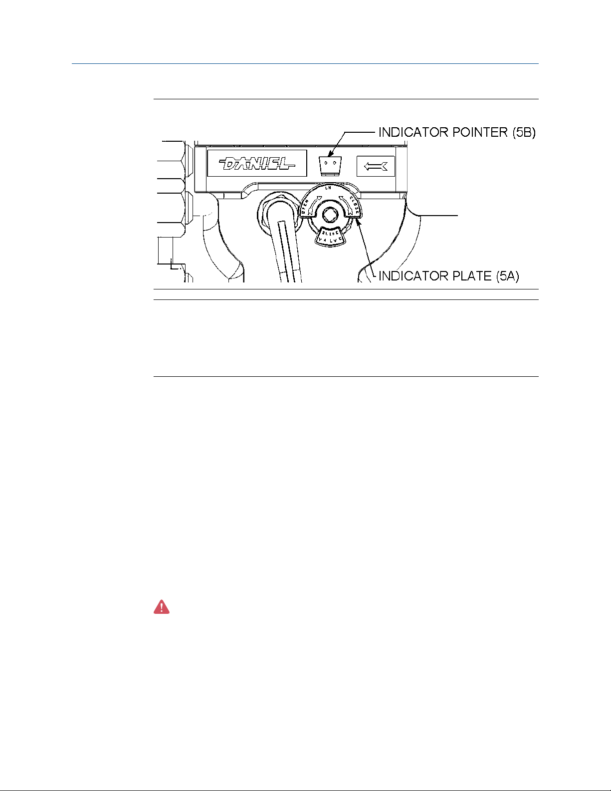
Normal operation conditions Owner and operator manual
October 2019 P/N 3-9008-001
Figure 4-6: Indicator Plate (5A) and Pointer (5B)
NOTICE
Prior to performing any maintenance or Orifice Plate (13) installation and removal
operations on the Senior, personnel must visually confirm the presence of the indicator
Plate (5A) on the Slide Valve Shaft (5) and the Indicator Pointer (5B) on the Body (4). Both
the indicator plate and the indicator pointer must be installed to operate this equipment
safely.
In preparation for the plate removal and installation process, the operator must evaluate
the meter system to determine the amount of time between the Top (14) fluid evacuation
and the plate change to the full replacement of the Clamping Bar (12 or 12HP), the Sealing
Bar (9 or 9HP), and the Sealing Bar Gasket (9A, 9A-HP or 9CF) back on the Top (14).
If the operator determines that the time between the Top (14) fluid evacuation and plate
change to the full replacement of the Clamping Bar (12 or 12HP), the Sealing Bar (9 or
9HP), and the Sealing Bar Gasket (9A, 9A-HP or 9CF) back on the Top (14) is less than 15
minutes, then the operator may use the "QUICK CHANGE" procedure.
If the operator determines that the time between the Top (14) fluid evacuation and the
plate change to the full replacement of the Clamping Bar (12 or 12HP), the Sealing Bar (9
or 9HP), and the Sealing Bar Gasket (9A, 9A-HP or 9CF) back on the Top (14) is greater
than 15 minutes, then the operator must use the "EXTENDED TIME" procedure.
If, for any reason, the operator cannot determine the total time between the Top (14) fluid
evacuation and the plate change to the full replacement of the Clamping Bar (12 or 12HP),
the Sealing Bar (9 or 9HP), and the Sealing Bar Gasket (9A, 9A-HP or 9CF) back on the Top
(14), then the operator must use the "EXTENDED TIME" procedure.
DANGER
FLUID EXPLOSION HAZARD
Follow the instructions below to avoid inadvertent or accidental opening of the slide
valve and the propulsion of fluid or internal components from the Top (14).
Failure to comply will result in death or serious injury.
The following are the conditions required to start the removal procedure of the orifice
plate:
84 Senior Orifice Fitting
Page 85

Owner and operator manual Normal operation conditions
P/N 3-9008-001 October 2019
• The Senior is operating at line pressure.
• The Plate Carrier (8DM or 8DMC) is located in the measurement position within the
Body (4).
• The Indicator Pointer (5B) and the Indicator Plate (5A) are installed on the Senior.
• The Slide Valve Shaft (5) is in the CLOSED position.
• The Equalizer Valve (1) is in the CLOSED position.
• The Bleeder Valve (10B) is in the CLOSED position.
• The Sealing Bar Gasket (9A, 9A-HP or 9CF), the Sealing Bar (9 or 9HP), and the
Clamping Bar (12 or 12HP) are fastened to the Top (14).
• Process temperature and ambient temperature values are within range of grease
charts.
• Process pressure values are within the range of grease charts.
“Quick change” procedure
To remove the Orifice Plate (13) from the Senior, the operator must first balance the
pressure between the Top (14) and the Body (4).
Procedure
Owner and operator manual 85
Page 86
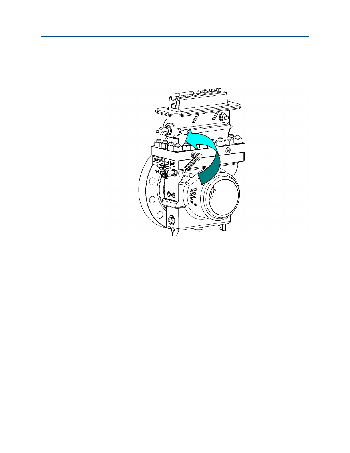
Normal operation conditions Owner and operator manual
October 2019 P/N 3-9008-001
1. Open the Equalizer Valve (1) one half to two full turns using the Operating Wrench
(2).
Figure 4-7: Step 1
86 Senior Orifice Fitting
Page 87
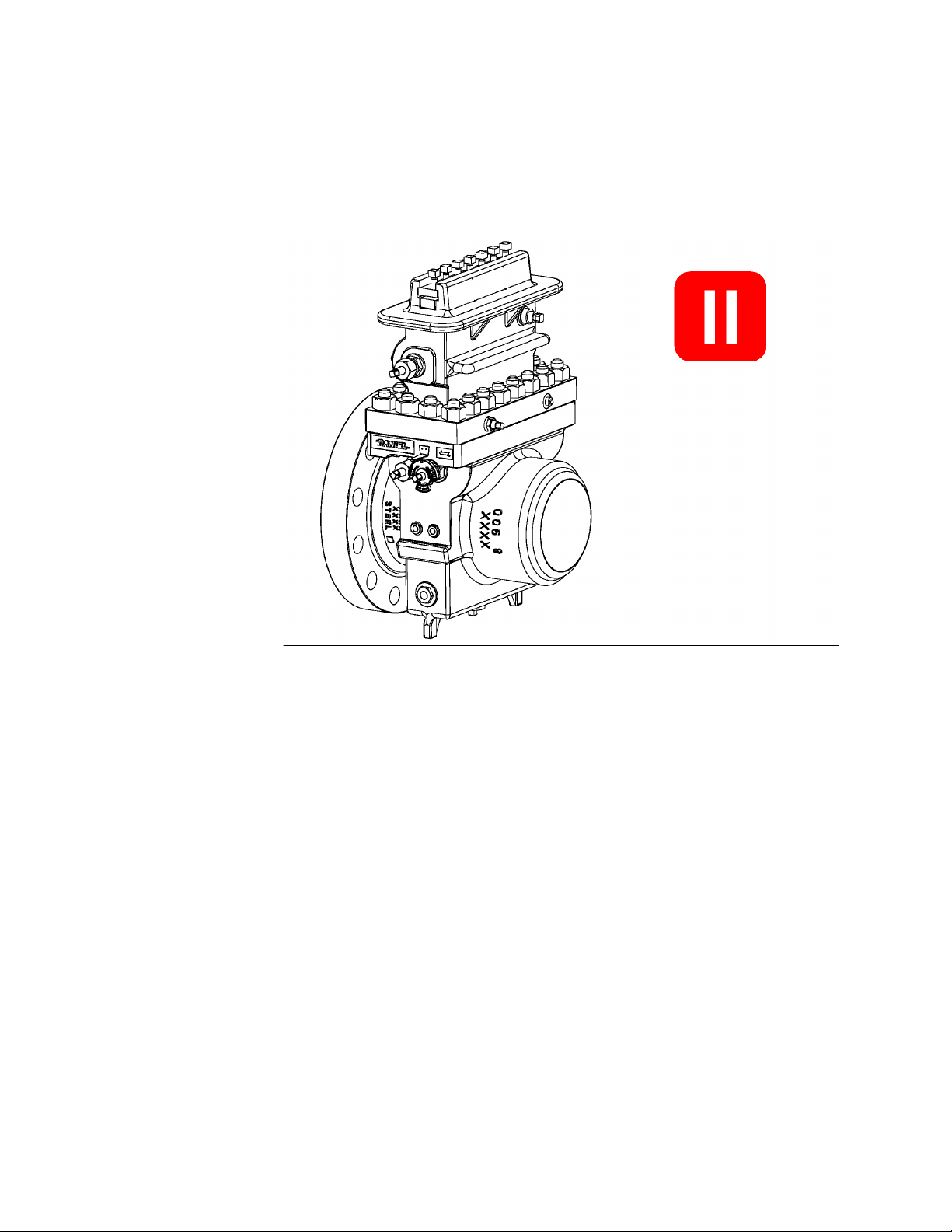
Owner and operator manual Normal operation conditions
P/N 3-9008-001 October 2019
2. Wait several seconds while the pressure in the Top (14) equalizes to that of the
Body (4).
Figure 4-8: Step 2
Owner and operator manual 87
Page 88
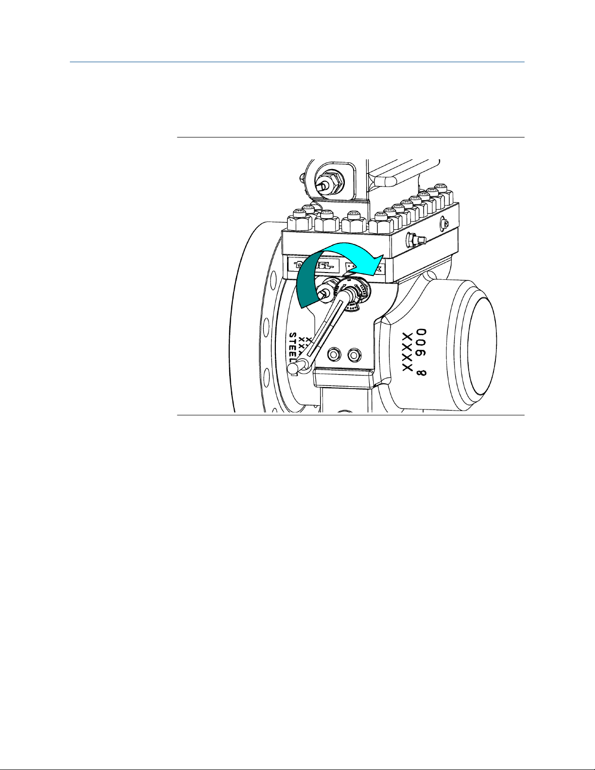
Normal operation conditions Owner and operator manual
October 2019 P/N 3-9008-001
3. Using the Operating Wrench (2) rotate the Slide Valve Shaft (5) until it stops and the
OPEN position specified on the Indicator Plate (5A) is in line with the Indicator
Pointer (5B).
Figure 4-9: Step 3
88 Senior Orifice Fitting
Page 89
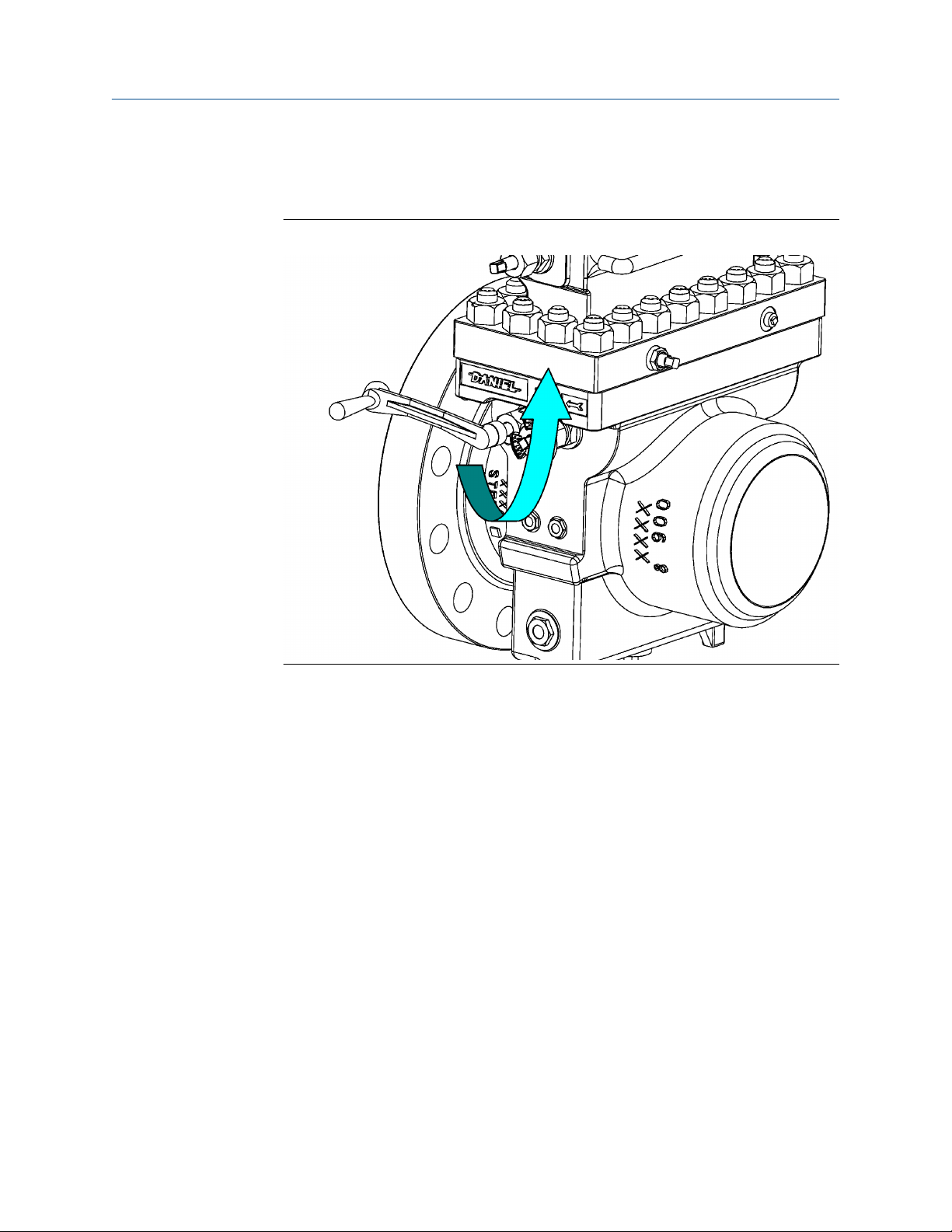
Owner and operator manual Normal operation conditions
P/N 3-9008-001 October 2019
4. Rotate the Lower Plate Carrier Shaft (6), located on the Body (4), using the
Operating Wrench (2) in a direction that will move the Plate Carrier (8DM or 8DMC)
out of the Body (4) into the Top (14).
Figure 4-10: Step 4
Owner and operator manual 89
Page 90

Normal operation conditions Owner and operator manual
October 2019 P/N 3-9008-001
5. Continue to rotate the Lower Plate Carrier Shaft (6) located on the Body (4) until the
Upper Plate Carrier Shaft (7) located in the Top (14) begins to rotate
Figure 4-11: Step 5
90 Senior Orifice Fitting
Page 91
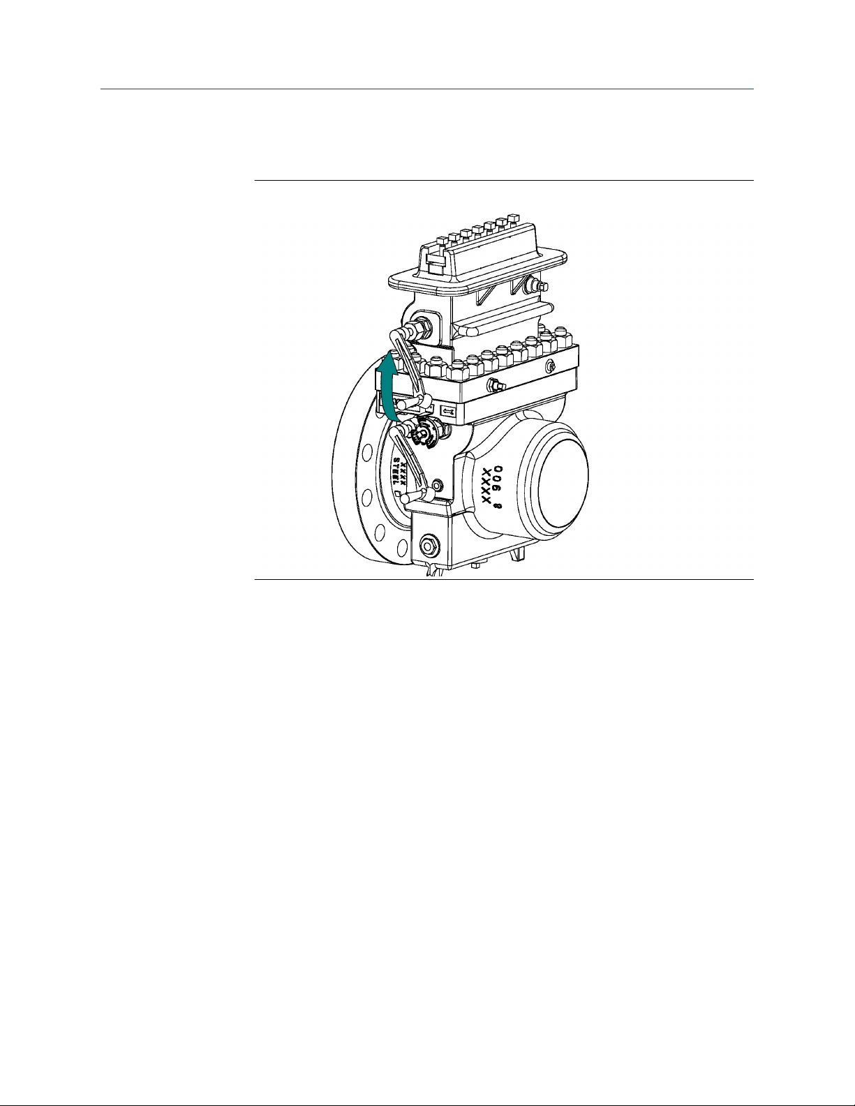
Owner and operator manual Normal operation conditions
P/N 3-9008-001 October 2019
6. Move the Operating Wrench (2) from the Lower Plate Carrier Shaft (6) located in the
Body (4) on the Upper Plate Carrier Shaft (7) located in the Top (14).
Figure 4-12: Step 6
Owner and operator manual 91
Page 92

Normal operation conditions Owner and operator manual
October 2019 P/N 3-9008-001
7. Rotate the Upper Plate Carrier Shaft (7) located in the Top (14) until the Plate
Carrier (8DM or 8DMC) stops against the Sealing Bar (9, 9HP).
Figure 4-13: Step 7
92 Senior Orifice Fitting
Page 93

Owner and operator manual Normal operation conditions
P/N 3-9008-001 October 2019
8. Close the Equalizer Valve (1) with the Operating Wrench (2).
Figure 4-14: Step 8
Owner and operator manual 93
Page 94

Normal operation conditions Owner and operator manual
October 2019 P/N 3-9008-001
9. Using the Operating Wrench (2) rotate the Slide Valve Shaft (5) until it stops and the
CLOSED position specified on the Indicator Plate (5A) is in line with the Indicator
Pointer (5B).
Figure 4-15: Step 9
94 Senior Orifice Fitting
Page 95

Owner and operator manual Normal operation conditions
P/N 3-9008-001 October 2019
10. Open the Bleeder Valve (10B) with the Operating Wrench (2).
Figure 4-16: Step 10
WARNING
PRESSURIZED FLUID HAZARD
When opening the bleeder valve (10B) or venting the Top (14) through the
bleeder valve (10B), direct the released pressurized fluid away from any individual
in accordance with local environment regulations to a safe area.
The bleeder valve (10B) releases pressurized fluid that may cause contamination
and/or accumulation of volatile gas mixtures. Failure to comply may cause death
or serious injury.
NOTICE
The pressure contained in the Top (14) must be lowered to ambient pressure in
order to begin any Orifice Plate (13) procedures. When lowering the pressure in the
Top (14), the operator must direct fluid or gas escaping from the Top (14) to a safe
area away from the operator, and in accordance with local environmental
regulations.
Steps 11 and 12 are ONLY required for the Seniors equipped with grease assisted,
metal-to-metal slide valves. Personnel operating the Senior equipped with O-ring
seal "soft seat" design slide valves skip to step 13.
Owner and operator manual 95
Page 96
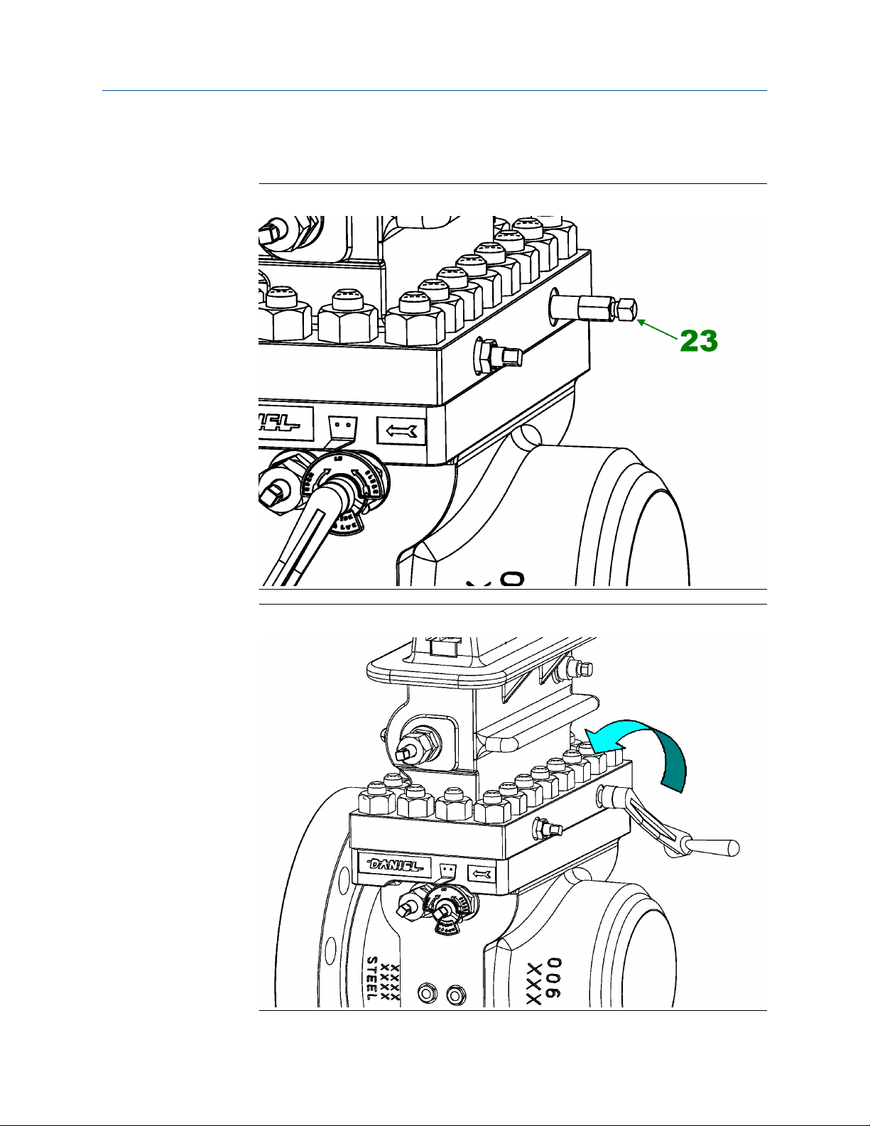
Normal operation conditions Owner and operator manual
October 2019 P/N 3-9008-001
11. Remove the stem from the Grease Gun (23) with the Operating Wrench (2) and
insert a lubricant stick into the Grease Gun (23).
Figure 4-17: Step 11
Figure 4-18: Step 11A
96 Senior Orifice Fitting
Page 97

Owner and operator manual Normal operation conditions
P/N 3-9008-001 October 2019
WARNING
PRESSURIZED FLUID HAZARD
Using the Grease Gun (23), inject grease into the slide valve seat channels at a
rate of 4 to 6 turns per minute and only under the following conditions:
• Bleeder Valve is open.
• Sealing bar/Clamping bar is in place and tight.
Injection of the grease at a faster rate will lead to the separation of the valve strip
from the valve seat, resulting in release of pressurized fluid which may cause
death or serious injury.
Owner and operator manual 97
Page 98
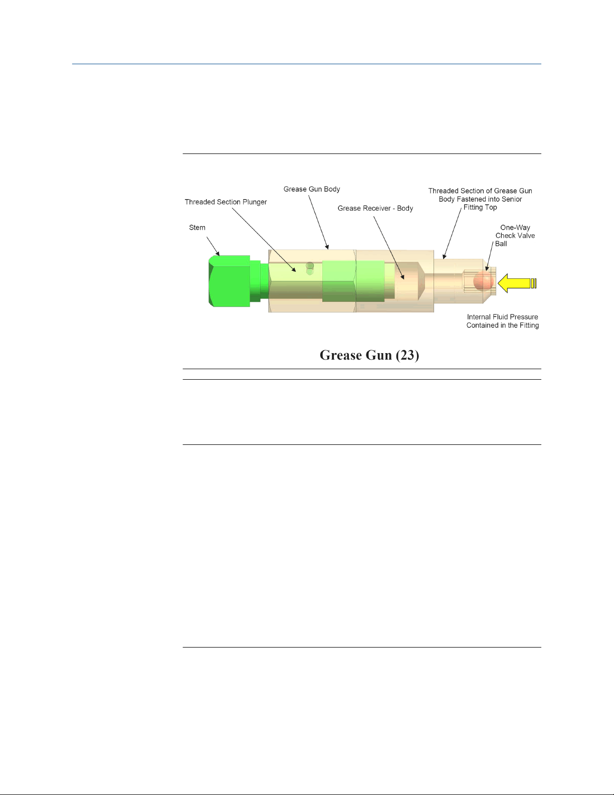
Normal operation conditions Owner and operator manual
October 2019 P/N 3-9008-001
12. Return the stem to the Grease Gun (23) and begin turning it clockwise by hand into
the Grease Gun (23) until resistance is felt. Once this is done, use the supplied
Operating Wrench (2) to continue to turn the stem clockwise, at a rate of 4 to 6
turns per minute.
Figure 4-19: Step 12
Important
By turning the stem of the Grease Gun (23) at a rate of 4 to 6 turns per minute, the
lubricant is forced through the Slide Valve Seat (18) channels at a rate that allows
the lubricant to travel freely, yet not separate the valve strip from the valve seat.
This method will keep fresh grease in the lubrication passages.
If the addition of grease does not reduce the flow from the open Bleeder Valve
(10B) to zero, follow these steps:
• Close the Bleeder Valve (10B),
• Open the Equalizer Valve (1), and move the Slide Valve Shaft (5) from the
CLOSED to the OPEN position, and back to the CLOSED position, repeating this
action several times.
• Return the Slide Valve Shaft (5) back to the CLOSED position.
• Close the Equalizer Valve (1) and repeat the lubrication process.
• Open the Bleeder Valve (10B).
If leakage is still present, close the Bleeder Valve (10B) and leave the Slide Valve
Shaft (5) in the CLOSED position and schedule maintenance on the Senior.
13. Monitor the fluid/gas pressure in the Top (14) until it is equal to ambient conditions.
Important
Once the Top (14) is equal to ambient conditions, the 15 minute countdown to
remove and install the Orifice Plate Carrier (8DM or 8DMC) begins.
Although the fluid pressure contained in the Top (14) is reduced to ambient
conditions in the following operations, there still remain remnants of the fluid in
98 Senior Orifice Fitting
Page 99
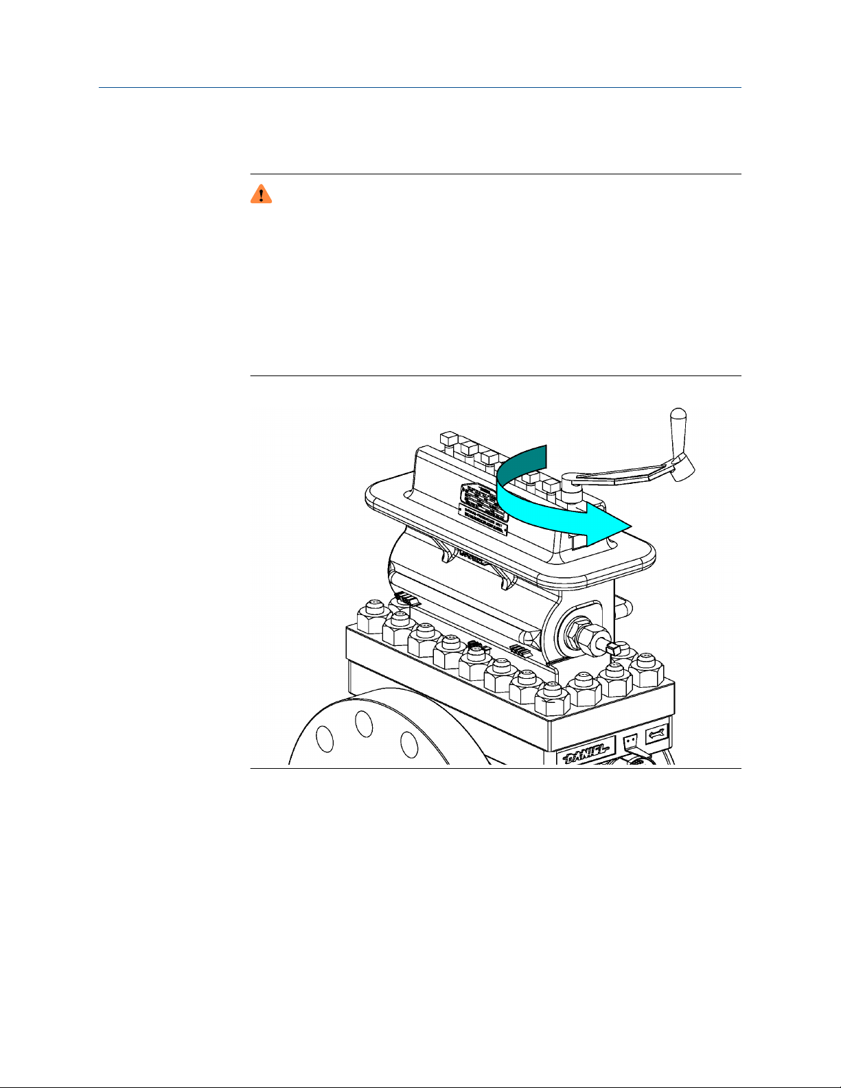
Owner and operator manual Normal operation conditions
P/N 3-9008-001 October 2019
that chamber. The operator must employ a system to address the remaining fluid
based upon the fluid's chemical composition and toxicity.
WARNING
RELEASE OF FLUIDS OR COMPONENTS HAZARD
The Clamping Bar (12 or 12HP) may not be securely in place. Sudden release of
fluid or internal components may occur. Never place the Operating Wrench (2)
on the Slide Valve Shaft (5), or any body part in front of the top opening in the
Top (14).
Failure to comply may cause death or serious injury.
14. Loosen each Clamping Bar Screw (11) located on the Clamping Bar (12 or 12HP)
approximately two turns with the Operating Wrench (2).
Figure 4-20: Step 14
Owner and operator manual 99
Page 100
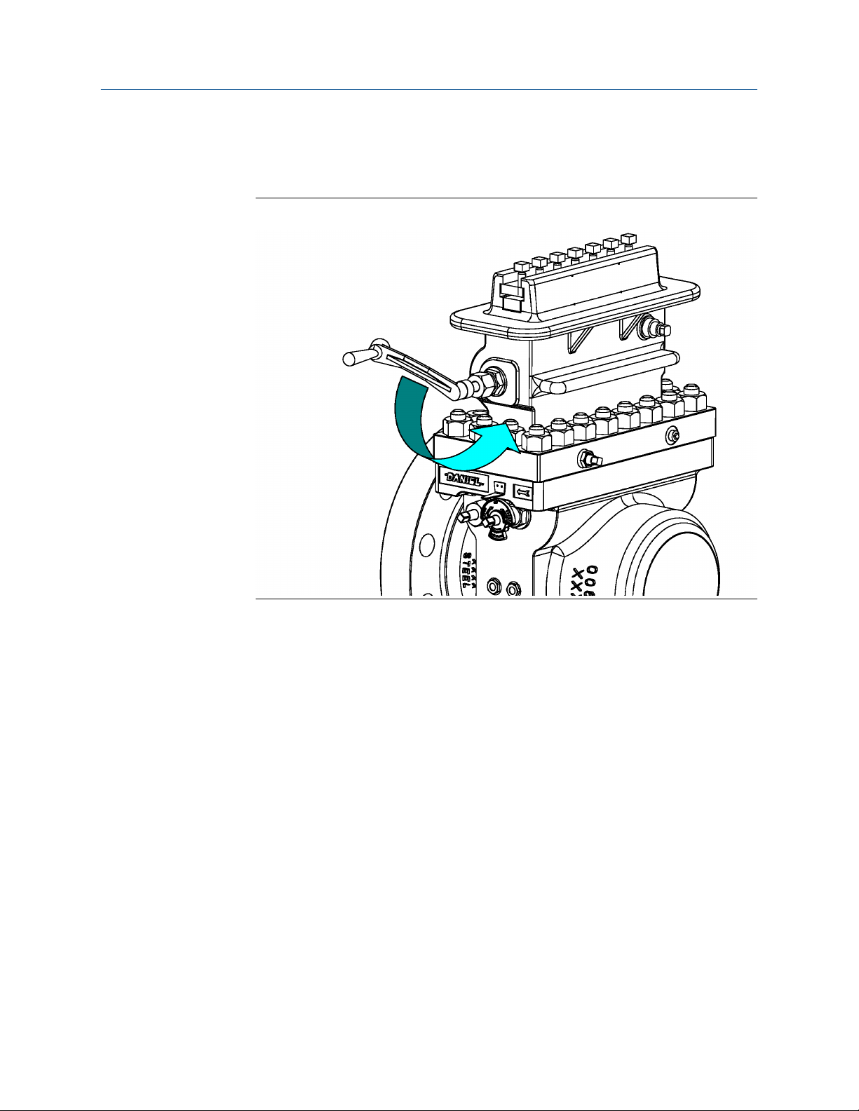
Normal operation conditions Owner and operator manual
October 2019 P/N 3-9008-001
15. Once the Clamping Bar Screws (11) are loose, rotate the Upper Plate Carrier Shaft
(7) located in the Top (14) with the Operating Wrench (2), until the Plate Carrier
(8DM or 8DMC) taps against the Sealing Bar (9 or 9HP) freeing it from the Top (14).
Figure 4-21: Step 15
100 Senior Orifice Fitting
 Loading...