

Page 1
Instruction Manual
D100345X012
March 2021
1805 Series Relief Valves
WARNING
!
Failure to follow these instructions or
to properly install and maintain this
equipment could result in an explosion
and/or re causing property damage and
personal injury or death.
Fisher™ relief valves must be installed,
operated and maintained in accordance
with federal, state and local codes, rules
and regulations, and Emerson Process
Management Regulator Technologies,
Inc. instructions.
1805 Series
If a leak develops or if the outlet
continually vents gas, service to the unit
may be required.
Failure to correct trouble could result in
a hazardous condition. Only a qualied
person must install or service the unit.
Call a gas service person to service the
unit. Only a qualied person must install
or service the 1805 Series Relief Valves.
Introduction
Scope of the Manual
This Instruction Manual provides installation,
adjustment, maintenance and parts ordering
information for 1805 Series relief valves.
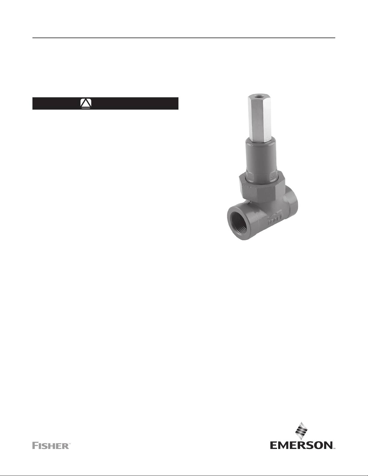
P1026
Figure 1. 1805 Series Relief Valve
Description
The 1805 Series relief valves are primarily designed
for use in farm tap applications where a safety relief
valve is needed between the first and second stage
regulators. The 1805 Series is suitable for service on
natural gas, air, propane or any operating medium that
is not corrosive to the internal parts. Relief pressure
ranges from 5 to 125 psi / 0.34 to 8.6 bar. Maximum
pressure, including buildup, is 150 psi / 10.3 bar.
Page 2
1805 Series
Specications
The Specications section lists the specications for the 1805 Series relief valve. The following information
is stamped on the relief valve at the factory: type number, date of manufacture, spring range, maximum inlet
pressure and maximum allowable inlet pressure.
Available Constructions
Type 1805-2: Cast iron spring case, closing cap
with 1/4 NPT vent placed over the adjusting screw.
Available in 3/4 and 1 NPT body sizes.
Type 1805-3: Cast iron spring case, closing cap
with 1/4 NPT vent placed over the adjusting screw.
Available in 1-1/2 and 2 NPT body sizes.
Body Sizes and End Connection Style
3/4, 1, 1-1/2 or 2 NPT
Maximum Inlet Pressure
150 psig / 10.3 bar including buildup
Relief Valve Set Pressure Ranges
See Table 1
Type 1805-4: Cast iron spring case. Available in
3/4 and 1 NPT body sizes.
Type 1805-5: Cast iron spring case.
Available in 1-1/2 and 2 NPT body sizes.
Type 1805-7: Cast iron spring case, closing
cap with 1/4 NPT vent placed over the adjusting
screw, screen in outlet. Available in 3/4 and 1 NPT
body sizes.
Body Style
Flow and IEC Sizing Coefficients
See Table 2
Temperature Capabilities
-20 to 150°F / -29 to 66°C
Approximate Shipping Weights
3/4 to 1 NPT bodies: 5 lbs / 2 kg
1-1/2 to 2 NPT bodies: 13 lbs / 6 kg
Globe body
1. The pressure/temperature limits in this Instruction Manual or any applicable standard limitation should not be exceeded.
Table 1. Relief Set Pressure Ranges
(1)
(1)
BODY SIZE
3/4 or 1 NPT
1-1/2 or 2 NPT
RELIEF PRESSURE RANGE
psig bar In. mm In. mm
5 to 35
10 to 60
20 to 125
5 to 20
10 to 50
35 to 125
0.34 to 2.4
0.69 to 4.1
1.4 to 8.6
0.34 to 1.4
0.69 to 3.5
2.4 to 8.6
SPRING
PART NUMBER
1B986027212
1B788327022
1B788427022
1D892327022
1D665927022
1E543627142
SPRING COLOR
CODE
Green
Silver
Blue
Red
Blue
Yellow
SPRING FREE LENGTH
2.25
2.13
1.94
2.94
2.50
2.31
Table 2. Flow and IEC Sizing Coecients
BODY SIZE C
3/4 to 1 NPT
1-1/2 to 2 NPT 0.94 0.44
1
35 0.79
K
m
IEC SIZING COEFFICIENTS
X
T
0.73 0.39
57.2
54.1
49.3
74.7
63.5
58.7
SPRING WIRE
0.12
0.14
0.18
0.17
0.22
0.28
F
D
DIAMETER
0.89
F
3.05
3.56
4.57
4.32
5.59
7.11
L
2
Page 3
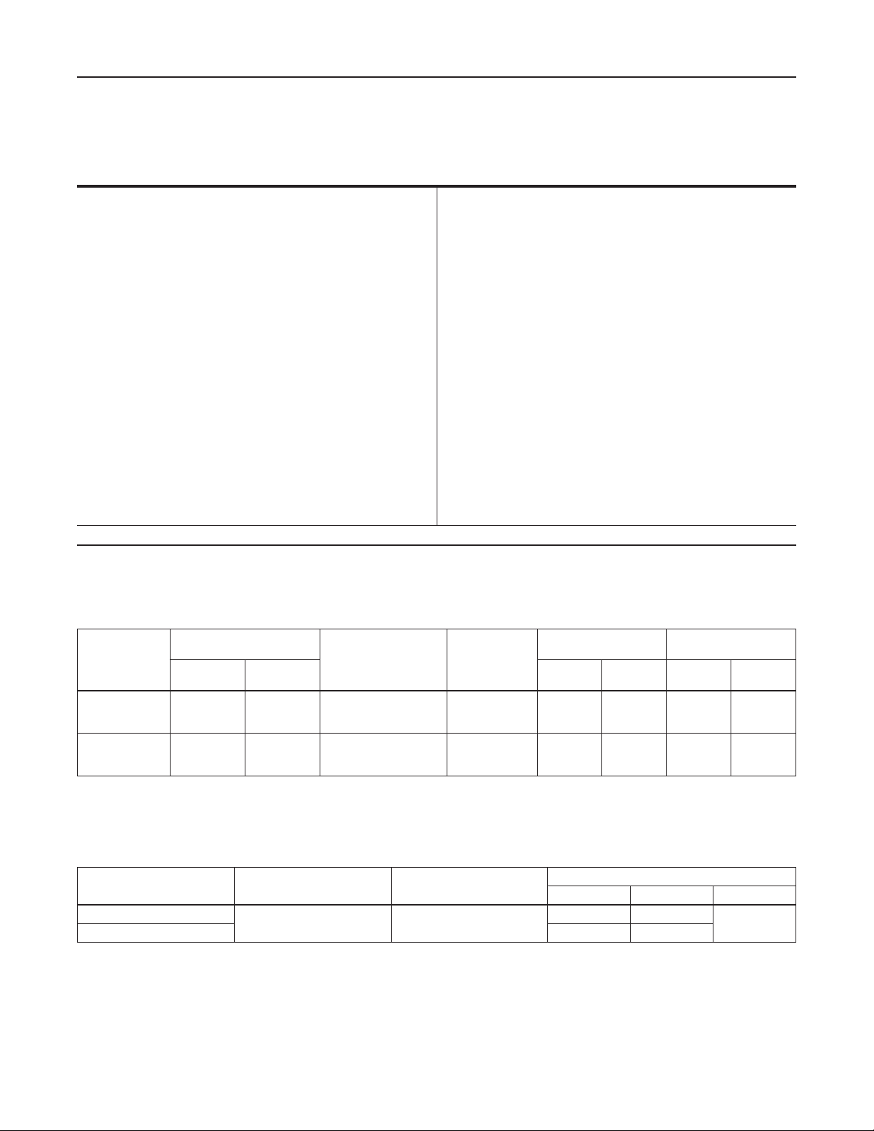
UPPER
SPRING
SEAT
1805 Series
A6671
INLET PRESSURE
OUTLET PRESSURE
ATMOSPHERIC PRESSURE
DIAPHRAGM
HEAD
UNION NUT
O-RING
HOLDER
O-RING WASHER
Figure 2. 1805 Series Operational Schematic
DIAPHRAGM
BODY
O-RING
VALVE GUIDE
ORIFICE
O-RING
Principle of Operation
See Figure 2. Relief valves respond to changes in
upstream pressure. If upstream pressure increases
and exceeds the relief valve setting, the valve will
open and allow gas to vent to the atmosphere. When
upstream pressure returns to normal level (below the
setting of the relief valve), the relief valve automatically
closes and normal system operation resumes.
In the 1805 Series relief valves, the upstream pressure
registers underneath the diaphragm. Gas reaches
the diaphragm through the space between the O-ring
holder and the valve guide orifice in 3/4 and 1 NPT
bodies or through registration holes in the valve guide
orifice in 1-1/2 and 2 NPT bodies. When the upstream
pressure increases beyond the spring setting, the force
on the diaphragm overcomes spring compression.
The O-ring holder moves upward, carrying the O-ring
away from the valve seat. This opens the flow line,
allows gas to flow to the atmosphere and relieves the
overpressure condition. When upstream pressure
registered on the diaphragm decreases to a level
below that of the spring setting of the relief valve, the
spring force pushes the diaphragm plate and O-ring
holder toward the valve seat. Contact between O-ring
and valve seat prevents further flow to atmosphere.
3
Page 4

1805 Series
TYPE CS200IN
SET AT 8 IN. W.C. / 20 mbar
TYPE 1805 SET AT 40 psi /
2.8 bar ROTATE PIPING SO
DISCHARGE FROM RELIEF
VALVE MISSES REGULATOR
TYPE 627
SET AT 25 psi / 1.7 bar
INLET PRESSURE UP TO
750 psi / 51.7 bar
AF9932
TEST GAUGE CONNECTION
PLUGGED-OPTIONAL
HAND VALVE
OR PLUG COCK
OPTIONAL
Figure 3. Typical Farm Tap Installation
Installation
After unpacking, check the relief valve for shipping
damage. Remove pipe scale and other foreign
material from the connecting pipeline. Coat the male
pipe threads with a suitable pipe compound. The unit
can be installed in any position as long as the ow is in
the direction indicated by the arrow cast on the body.
Protect the outlet and vents from entrance of rain,
snow or other foreign material that may plug them.
Outdoor installations should include a rain cap
over the vents and outlet if they point upward.
Periodically check the openings to ensure that they are
not plugged.
Protect the relief valve against damage from vehicles
or other external sources.
Vents
WARNING
!
Venting gas may accumulate and be
an explosion hazard under enclosed
conditions such as in pit or underground
installations. Install remote vent lines to
carry gas to a safe area.
If remote vent lines are necessary, use the
Type 1805-2, -3 or -7 which have 1/4 NPT vent
connections in the closing cap. Remove the screen
if one is present in the outlet, and install remote vent
lines in the outlet and closing cap openings. Remote
vent lines must have the largest practical diameter as
possible. The vent lines should be as short as possible
with a minimum number of bends or elbows.
4
Page 5

1805 Series
Overpressure
Relief pressure ratings are from 5 to 125 psi / 0.34
to 8.6 bar. The maximum inlet pressure, including
buildup, is 150 psi / 10.3 bar. System operation
within these limitations does not eliminate the
possibility of damage from external sources or
from debris in the gas line. The relief valve should
be inspected for damage regularly and after any
overpressure condition.
Startup
Key numbers are shown in Figure 4. With proper
installation completed and system equipment properly
adjusted, close any vent valves and slowly open the
upstream shut-o valve while using pressure gauges
to monitor pressure.
If set pressure adjustment is necessary, monitor
the inlet pressure with a gauge during the
adjustment procedure.
Adjustment
The range of allowable pressure settings is stamped
on the spring case (Types 1805-2, -4 and -7) or on the
nameplate (Types 1805-3 and -5). If a pressure setting
beyond the indicated range is required, substitute
the appropriate spring. Be sure to label the relief
valve to indicate the new pressure range. Always
use a pressure gauge to monitor pressure when
making adjustments.
1. On Types 1805-2, -3 and -7 remove the closing
cap (key 17).
2. Loosen hex nut (key 15).
3. To increase the relief setting, turn the adjusting
screw (key 14) clockwise. To decrease the relief
setting, turn the adjusting screw counterclockwise.
4. Tighten the hex nut.
Due to normal wear that may occur in relief valves,
the O-rings and diaphragm must be inspected
periodically and replaced as necessary. The frequency
of inspection and replacement depends upon the
severity of service conditions or the requirements of
state and federal laws. Instructions are given below for
disassembly of the relief valve and replacement of the
O-rings and diaphragm. The 1805 Series relief valves
do not have to be removed from the pipeline to inspect
internal parts. Refer to Figure 4 while servicing the
relief valves.
Disassembly/Assembly
1. To ease spring compression, remove the closing
cap (key 17, Types 1805-2, -3 and -7), loosen
the hex nut (key 15) and turn the adjusting screw
(key 14) counterclockwise.
2. Unscrew the union nut (key 16) and remove it
with the spring case (key 13), spring (key 11) and
upper spring seat (key 12).
3. Pull the O-ring holder (key 4) out of the valve
guide orifice (key 2).
4. Remove the diaphragm cap screw (key 10) from
the O-ring holder. Take off the diaphragm plate
(key 9) and inspect the diaphragm (key 8).
5. Take the machine screw (key 7) out of the
opposite end of O-ring holder, remove the O-ring
washer (key 6) and inspect the O-ring (key 5).
6. Remove the valve guide orifice (key 2) from the
body and check the Tetraseal® O-ring (key 3).
7. Reassemble the relief valve in reverse order of
the above steps. To ensure proper slack in the
diaphragm, tighten the union nut finger-tight only.
Turn the adjusting screw clockwise to apply some
spring force to the diaphragm. Complete the
tightening of the union nut.
Shutdown
Close the upstream shut-o valve and release all
pressure from the relief valve.
Maintenance
WARNING
!
To avoid personal injury and equipment
damage, isolate the relief valve from
all pressure. Cautiously release
pressure from the relief valve before
attempting disassembly.
Tetraseal® is a mark owned by of Goshen Rubber Company.
Parts Ordering
When corresponding with your local Sales Oce or the
factory concerning these relief valves, include the type
number and all other pertinent information stamped
on the spring case, closing cap or on the nameplate.
Specify the eleven-character part number when
ordering new parts from the following parts list.
When ordering replacement parts, reference the key
number of each needed part as found in the following
parts list. Separate kit containing all recommended
spare parts is available.
5
Page 6

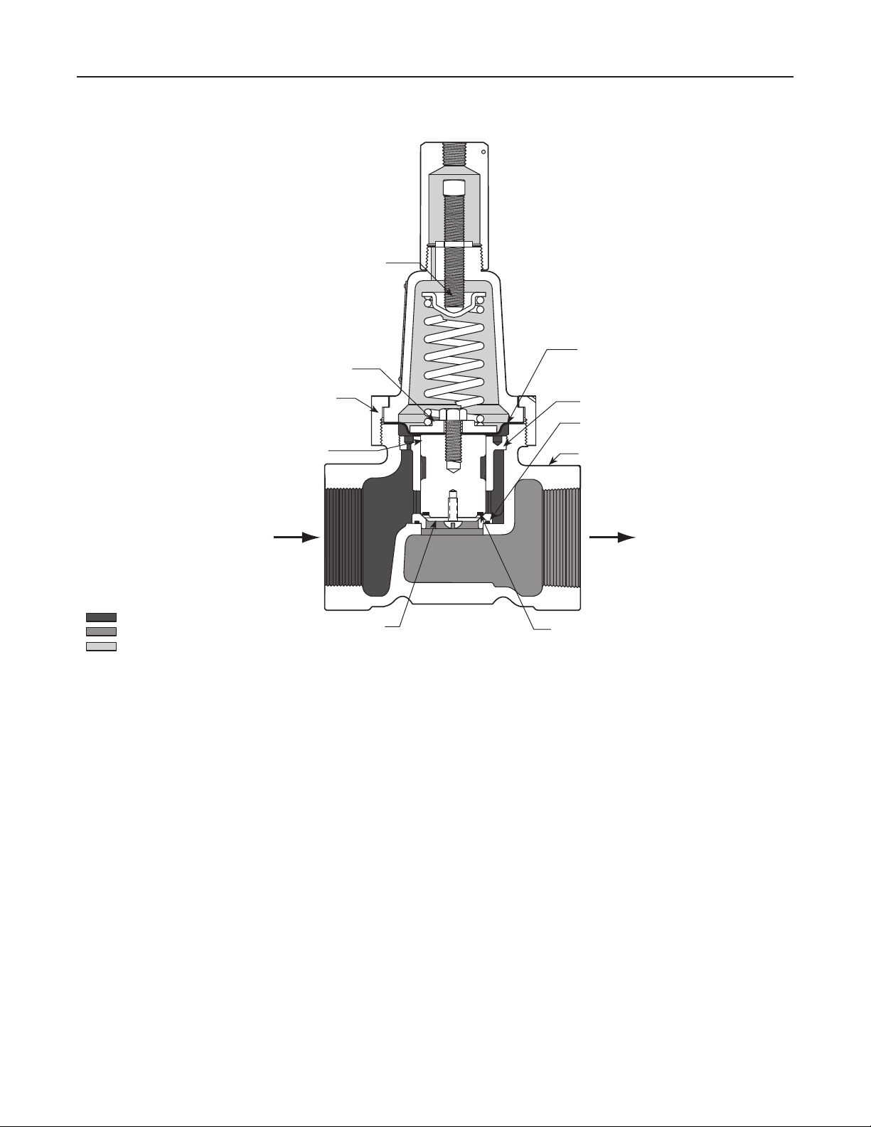
1805 Series
17
14
15
25
13
12
18
19
11
10
9
16
8
2
4
5
3
BE9481
6
1
7
Figure 4. Type 1805-3 Relief Valve Assembly (Also typical of Type 1805 Relief Valves)
6
Page 7

Parts List
Key Description Part Number
Parts kit
(included are keys 3, 5 and 8)
3/4 and 1 NPT body sizes R1805X00012
1-1/2 and 2 NPT body sizes R1805X00022
1 Valve Body
Types 1805-2 and -4
3/4 NPT
Cast iron 1E621119012
Ductile iron (NACE) 1F192019062
1 NPT
Cast iron 1E621219012
Ductile iron (NACE) 1F192119062
Types 1805-3 and -5
1-1/2 NPT Cast iron 1E824019012
2 NPT Cast iron 1E824319012
Type 1805-7
3/4 NPT Cast iron 1H242519012
1 NPT Cast iron 1H242619012
2 Valve Guide Orifice, Aluminum
3/4 and 1 NPT body sizes 1K314709012
1-1/2 and 2 NPT body sizes 1N939909012
3* Tetraseal®/O-ring, Nitrile (NBR)
3/4 and 1 NPT body sizes 1K314806992
1-1/2 and 2 NPT body sizes 1N940306562
4 O-ring Holder, Aluminum
3/4 and 1 NPT body sizes 1E621609092
1-1/2 and 2 NPT body sizes 1E824609092
5* O-ring, Nitrile (NBR)
3/4 and 1 NPT body sizes 1D288806992
1-1/2 and 2 NPT body sizes 1C5622X0022
6 O-ring Washer Stainless steel
3/4 and 1 NPT body sizes 1D335935072
1-1/2 and 2 NPT body sizes 1E824235072
7 Machine Screw, Steel
3/4 and 1 NPT body sizes 16A0429X012
1-1/2 and 2 NPT body sizes 1B420428982
8* Diaphragm, Nitrile (NBR)
3/4 and 1 NPT body sizes 1E621702052
1-1/2 and 2 NPT body sizes 1E824102052
9 Diaphragm Plate, Brass
3/4 and 1 NPT body sizes 1E621814012
1-1/2 and 2 NPT body sizes 1E824714012
1805 Series
Key Description Part Number
10 Cap Screw, Zinc-plated steel
3/4 and 1 NPT body sizes 1B290524052
1-1/2 and 2 NPT body sizes 1E760324052
11 Spring, Zinc-plated steel
3/4 and 1 NPT body sizes
5 to 35 psig / 0.34 to 2.4 bar 1B986027212
10 to 60 psig / 0.69 to 4.1 bar 1B788327022
20 to 125 psig / 1.4 to 8.6 bar 1B788427022
1-1/2 and 2 NPT body sizes
5 to 20 psig / 0.34 to 1.4 bar 1D892327022
10 to 50 psig / 0.69 to 3.5 bar 1D665927022
35 to 125 psig / 2.4 to 8.6 bar 1E543627142
12 Upper Spring Seat, Steel
3/4 and 1 NPT body sizes 1B798525062
1-1/2 and 2 NPT body sizes 1D667125072
13 Spring Case, Cast Iron
3/4 and 1 NPT body sizes 2E770819012
1-1/2 and 2 NPT body sizes 2E824919042
14 Adjusting Screw, Brass
3/4 and 1 NPT body sizes 1E770914012
1-1/2 and 2 NPT body sizes 1E543214012
15 Hex Nut, Zinc-plated steel
3/4 and 1 NPT body sizes 1A946324122
1-1/2 and 2 NPT body sizes 1D667728982
16 Union Nut, Ductile iron
3/4 and 1 NPT body sizes 1E471119062
1-1/2 and 2 NPT body sizes 1E766619062
17 Closing Cap, Brass
Types 1805-2 and -7 1E770614012
Type 1805-3 1E823914012
19 Drive Screw, Steel (4 required)
1-1/2 and 2 NPT body sizes 1E501728982
20 Screen, Stainless steel (not shown)
Type 1805-7 1E564843122
21 Snap Ring, 302 Stainles steel (not shown)
Type 1805-7 1E564937022
22 NACE Tag, 18-8 Stainless steel (not shown) 19A6034X012
23 Tag Wire, 304 Stainless steel (not shown) 1U7581X0022
24 Pipe Plug, Alloy-plated steel 1C333528992
25 O-ring
3/4 and 1 NPT body sizes 1F463606992
1-1/2 and 2 NPT body sizes T14380T0012
*Recommended spare part.
Tetraseal® is a mark owned by of Goshen Rubber Company.
7
Page 8

1805 Series
Webadmin.Regulators@emerson.com
Fisher.com
Emerson Automation Solutions
Americas
McKinney, Texas 75070 USA
T +1 800 558 5853
+1 972 548 3574
Europe
Bologna 40013, Italy
T +39 051 419 0611
Facebook.com/EmersonAutomationSolutions
LinkedIn.com/company/emerson-automation-solutions
Twitter.com/emr_automation
Asia Pacic
Singapore 128461, Singapore
T +65 6777 8211
Middle East and Africa
Dubai, United Arab Emirates
T +971 4 811 8100
D100345X012 © 1975, 2021 Emerson Process Management Regulator
Technologies, Inc. All rights reserved. 03/21.
The Emerson logo is a trademark and service mark of Emerson Electric
Co. All other marks are the property of their prospective owners.
Fisher™ is a mark owned by Fisher Controls International LLC, a business
of Emerson Automation Solutions.
The contents of this publication are presented for informational purposes
only, and while every eort has been made to ensure their accuracy,
they are not to be construed as warranties or guarantees, express or
implied, regarding the products or services described herein or their use
or applicability. All sales are governed by our terms and conditions, which
are available upon request. We reserve the right to modify or improve the
designs or specications of such products at any time without notice.
Emerson Process Management Regulator Technologies, Inc. does
not assume responsibility for the selection, use or maintenance of any
product. Responsibility for proper selection, use and maintenance of any
Emerson Process Management Regulator Technologies, Inc. product
remains solely with the purchaser.
 Loading...