

Page 1
Liebert® CW™ Thermal Management System
System Design Manual—26 kW — 400 kW, Upflow and Downflow, 50 Hz – 60 Hz
Page 2

Page 3

Table of Content
1.0 Nomenclature and Components . . . . . . . . . . . . . . . . . . . . . . . . . . . . . . . . 1
1.1 Liebert CW Nomenclature. . . . . . . . . . . . . . . . . . . . . . . . . . . . . . . . . . . . . . . . . . . . . . . . . . 1
1.2 Components . . . . . . . . . . . . . . . . . . . . . . . . . . . . . . . . . . . . . . . . . . . . . . . . . . . . . . . . . . . . 3
1.3 Blower Configurations. . . . . . . . . . . . . . . . . . . . . . . . . . . . . . . . . . . . . . . . . . . . . . . . . . . . . 5
2.0 Liebert CW System Data. . . . . . . . . . . . . . . . . . . . . . . . . . . . . . . . . . . . . . . 9
3.0 Electrical Data . . . . . . . . . . . . . . . . . . . . . . . . . . . . . . . . . . . . . . . . . . . . . . 17
4.0 Dimensions . . . . . . . . . . . . . . . . . . . . . . . . . . . . . . . . . . . . . . . . . . . . . . . . 23
4.1 Location Considerations . . . . . . . . . . . . . . . . . . . . . . . . . . . . . . . . . . . . . . . . . . . . . . . . . . 23
4.2 Cabinet and Floor-planning
Dimensions—Downflow Models with EC Fans. . . . . . . . . . . . . . . . . . . . . . . . . . . . . . . 24
4.3 Cabinet and Floor-planning
Dimensions—Upflow Models with EC Fans. . . . . . . . . . . . . . . . . . . . . . . . . . . . . . . . . 32
4.4 Cabinet and Floor-planning Dimensions
—Downflow Models with Forward-curved Blowers . . . . . . . . . . . . . . . . . . . . . . . . . . . 36
4.5 Cabinet and Floor-planning Dimensions
—Upflow Models with Forward-curved Blowers. . . . . . . . . . . . . . . . . . . . . . . . . . . . . . 38
4.6 Floor-stand Dimensions—Units with EC Fans . . . . . . . . . . . . . . . . . . . . . . . . . . . . . . . . . 40
4.7 Floor-stand Dimensions—Units with Forward-curved Blowers. . . . . . . . . . . . . . . . . . . . . 46
4.8 Plenum Dimensions—Units with EC Fans . . . . . . . . . . . . . . . . . . . . . . . . . . . . . . . . . . . . 48
4.9 Plenum Dimensions—Units with Forward-curved Blowers. . . . . . . . . . . . . . . . . . . . . . . . 50
5.0 Piping . . . . . . . . . . . . . . . . . . . . . . . . . . . . . . . . . . . . . . . . . . . . . . . . . . . . . 53
5.1 Piping General Arrangement. . . . . . . . . . . . . . . . . . . . . . . . . . . . . . . . . . . . . . . . . . . . . . . 53
5.2 Piping Connections—Downflow Models with EC Fans. . . . . . . . . . . . . . . . . . . . . . . . . . . 56
5.3 Piping Connections—Downflow Models with Forward-curved Blowers . . . . . . . . . . . . . . 62
5.4 Piping Connections—Upflow Models . . . . . . . . . . . . . . . . . . . . . . . . . . . . . . . . . . . . . . . . 64
iLiebert
®
CW™ System Design Manual
Page 4

6.0 Electrical Field Connections . . . . . . . . . . . . . . . . . . . . . . . . . . . . . . . . . . 67
6.1 Electrical Field Connections—Downflow Models . . . . . . . . . . . . . . . . . . . . . . . . . . . . . . . 67
6.1.1 Standard Electrical Connections for Downflow Models CW146 and CW181 . . . . . . . . . . 71
6.1.2 Optional Electrical Connections for Downflow Models CW146 and CW181. . . . . . . . . . . 72
6.1.3 Optional Low-Voltage Terminal Package Connections. . . . . . . . . . . . . . . . . . . . . . . . . . . 72
6.1.4 Optional Low-Voltage Terminal Package Connections
for Downflow Models CW146 and CW181. . . . . . . . . . . . . . . . . . . . . . . . . . . . . . . . . . . 73
6.2 Electrical Field Connections—Upflow Models. . . . . . . . . . . . . . . . . . . . . . . . . . . . . . . . . . 74
Appendix A: Optional Configuration
for Liebert CW Seismic Application . . . . . . . . . . . . . . . . . . . . . . . . . . . 81
A.1 Seismic Certification Criteria. . . . . . . . . . . . . . . . . . . . . . . . . . . . . . . . . . . . . . . . . . . . . . . 81
A.1 Site Requirements . . . . . . . . . . . . . . . . . . . . . . . . . . . . . . . . . . . . . . . . . . . . . . . . . . . . . . 81
A.2 Requirements for Seismic Anchorage . . . . . . . . . . . . . . . . . . . . . . . . . . . . . . . . . . . . . . . 82
A.3 Anchor and Load Requirements of Seismic Installation . . . . . . . . . . . . . . . . . . . . . . . . . . 82
Appendix B: Optional Liebert Air Economizer™ for Liebert CW . . . . . . . . 95
B.1 Customer-supplied Equipment and Ductwork. . . . . . . . . . . . . . . . . . . . . . . . . . . . . . . . . . 95
Appendix C: Guide Specifications—Chilled Water
Environmental Control System. . . . . . . . . . . . . . . . . . . . . . . . . . . . . . 105
Liebert® CW™ System Design Manual ii
Page 5

List of Figures
Figure 1-1: Downflow model component locations . . . . . . . . . . . . . . . . . . . . . . . . . . . . . . . . . . . . . . . . . . . . . . . . . 3
Figure 1-2: Upflow model component locations. . . . . . . . . . . . . . . . . . . . . . . . . . . . . . . . . . . . . . . . . . . . . . . . . . . . 4
Figure 1-3: Blower configurations—Downflow, front and rear supply, EC fans . . . . . . . . . . . . . . . . . . . . . . . . . . . . 5
Figure 1-4: Blower configurations—Downflow, bottom and under-floor supply, EC fans. . . . . . . . . . . . . . . . . . . . . 5
Figure 1-5: Blower configurations—Downflow, under-floor supply, forward-curved blowers . . . . . . . . . . . . . . . . . . 6
Figure 1-6: Blower configurations—Upflow, EC fans in plenum. . . . . . . . . . . . . . . . . . . . . . . . . . . . . . . . . . . . . . . . 6
Figure 1-7: Blower configurations—Upflow, front return, forward-curved blowers. . . . . . . . . . . . . . . . . . . . . . . . . . 7
Figure 1-8: Blower configurations—Upflow, rear return, forward-curved blowers . . . . . . . . . . . . . . . . . . . . . . . . . . 7
Figure 4-1: Cabinet and floor-planning dimensions, downflow, CW026 – CW084 with EC fans . . . . . . . . . . . . . . 24
Figure 4-2: Cabinet and floor-planning dimensions, downflow,
CW026, CW038 and CW041, with EC fans, front discharge. . . . . . . . . . . . . . . . . . . . . . . . . . . . 25
Figure 4-3: Cabinet and floor-planning dimensions, downflow,
CW051, CW060, CW076 and CW084, with EC fans, front discharge. . . . . . . . . . . . . . . . . . . . . 26
Figure 4-4: Cabinet and floor-planning dimensions, downflow,
CW089, CW106 and CW114 with EC fans . . . . . . . . . . . . . . . . . . . . . . . . . . . . . . . . . . . . . . . . . 27
Figure 4-5: Cabinet and floor-planning dimensions, downflow,
CW089, CW106 and CW114 with EC fans, front discharge . . . . . . . . . . . . . . . . . . . . . . . . . . . . 28
Figure 4-6: Cabinet and floor-planning dimensions, downflow, CW146 and CW181 with EC fans . . . . . . . . . . . . 29
Figure 4-7: Cabinet and floor-planning dimensions, downflow
CW146 and CW181, with EC fans, front discharge . . . . . . . . . . . . . . . . . . . . . . . . . . . . . . . . . . . 30
Figure 4-8: Cabinet and floor-planning dimensions, downflow,
CW300, CW400 with EC fans and filter plenums. . . . . . . . . . . . . . . . . . . . . . . . . . . . . . . . . . . . . 31
Figure 4-9: Cabinet and floor-planning dimensions, upflow, CW026 – CW084 with EC fans, front air return. . . . 32
Figure 4-10: Cabinet and floor-planning dimensions, upflow,
CW026 - CW084 with EC fans, rear and bottom air return . . . . . . . . . . . . . . . . . . . . . . . . . . . . . 33
Figure 4-11: Cabinet and floor-planning dimensions, upflow, CW106, CW114 with EC fans, front return. . . . . . . 34
Figure 4-12: Cabinet and floor-planning dimensions, upflow, CW106, CW114 with EC fans, rear return . . . . . . . 35
Figure 4-13: Cabinet and floor-planning dimensions, downflow,
CW026 - CW084, with forward-curved blowers. . . . . . . . . . . . . . . . . . . . . . . . . . . . . . . . . . . . . . 36
Figure 4-14: Cabinet and floor-planning dimensions, downflow,
CW106 and CW114 with forward-curved blowers . . . . . . . . . . . . . . . . . . . . . . . . . . . . . . . . . . . . 37
Figure 4-15: Cabinet and Floor-planning dimensions, upflow, CW026 – CW084 with forward-curved blowers . . 38
Figure 4-16: Cabinet and Floor-planning dimensions, upflow,
CW106 and CW114 with forward-curved blowers . . . . . . . . . . . . . . . . . . . . . . . . . . . . . . . . . . . . 39
Figure 4-17: Floor-stand and floor-planning dimensions, downflow, CW026 – CW041 with EC fans . . . . . . . . . . 40
Figure 4-18: Floor-stand and floor-planning dimensions, downflow, CW051 and CW060 with EC fans . . . . . . . . 41
Figure 4-19: Floor-stand and floor-planning dimensions, downflow, CW076 and CW084 with EC fans . . . . . . . . 42
Figure 4-20: Floor-stand and floor-planning dimensions, downflow, CW089, CW106 and CW114 with EC fans . 43
Figure 4-21: Floor-stand and floor-planning dimensions, downflow, CW089, CW106 and CW114 with EC fans . 44
Figure 4-22: Floor-stand and floor-planning dimensions, downflow, CW300 and CW400 with EC fans . . . . . . . . 45
Figure 4-23: Floor-stand planning dimensions, CW026 – CW084 with forward-cu rved blowers. . . . . . . . . . . . . . 46
Figure 4-24: Floor-stand planning dimensions, CW106 and CW114 with forward-curved blowers. . . . . . . . . . . . 47
Figure 4-25: Plenum dimensions, upflow, CW026 — CW084 with EC fans . . . . . . . . . . . . . . . . . . . . . . . . . . . . . 48
Figure 4-26: Plenum dimensions, upflow, CW106, CW114 with EC fans . . . . . . . . . . . . . . . . . . . . . . . . . . . . . . . 49
iii Liebert® CW™ System Design Manual
Page 6

Figure 4-27: Plenum dimensions, upflow, CW026 – CW084 with forward-curved blowers . . . . . . . . . . . . . . . . . . 50
Figure 4-28: Plenum dimensions, upflow. CW106 and CW11 4 with forward-curved blowers . . . . . . . . . . . . . . . . 51
Figure 5-1: Piping general arrangement, downflow, CW026 – CW114 . . . . . . . . . . . . . . . . . . . . . . . . . . . . . . . . . 53
Figure 5-2: Piping general arrangement, downflow, CW146 – CW181 . . . . . . . . . . . . . . . . . . . . . . . . . . . . . . . . . 54
Figure 5-3: Piping general arrangement, upflow, CW026 – CW114 . . . . . . . . . . . . . . . . . . . . . . . . . . . . . . . . . . . 55
Figure 5-4: Primary connection locations, downflow, CW026 – CW041 with EC fans. . . . . . . . . . . . . . . . . . . . . . 56
Figure 5-5: Primary connection locations, downflow, CW051 and CW060 with EC fans. . . . . . . . . . . . . . . . . . . . 57
Figure 5-6: Primary connection locations, downflow, CW076 – CW084 with EC fans. . . . . . . . . . . . . . . . . . . . . . 58
Figure 5-7: Primary connection locations, downflow, CW089, CW106 and CW114 with EC fans. . . . . . . . . . . . . 59
Figure 5-8: Primary connection locations, downflow, CW146 and CW181 with EC fans. . . . . . . . . . . . . . . . . . . . 60
Figure 5-9: Primary connection locations, downflow, CW300 and CW400 with EC fans. . . . . . . . . . . . . . . . . . . . 61
Figure 5-10: Piping connections, downflow, CW026 – CW084 with forward-curved blowers . . . . . . . . . . . . . . . . 62
Figure 5-11: Piping connections, downflow, CW106 and CW114 with forward-curved blowers . . . . . . . . . . . . . . 63
Figure 5-12: Piping connections, upflow, CW026 – CW084 . . . . . . . . . . . . . . . . . . . . . . . . . . . . . . . . . . . . . . . . . 64
Figure 5-13: Piping connections, upflow, CW106 and CW114. . . . . . . . . . . . . . . . . . . . . . . . . . . . . . . . . . . . . . . . 65
Figure 6-1: Electrical field connections, downflow, CW026 – CW084 . . . . . . . . . . . . . . . . . . . . . . . . . . . . . . . . . . 67
Figure 6-2: Electrical field connections (Ethernet), downflow, CW026 – CW084. . . . . . . . . . . . . . . . . . . . . . . . . . 68
Figure 6-3: Electrical field connections, downflow, CW089, CW106 and CW114 . . . . . . . . . . . . . . . . . . . . . . . . . 69
Figure 6-4: Electrical field connections (Ethernet), downflow, CW089, CW106 and CW114. . . . . . . . . . . . . . . . . 70
Figure 6-5: Electrical field connections, downflow, CW146 and CW181 with EC fans . . . . . . . . . . . . . . . . . . . . . 71
Figure 6-6: Electrical field connections (high voltage), upflow, CW026 – CW084 . . . . . . . . . . . . . . . . . . . . . . . . . 74
Figure 6-7: Electrical field connections (low voltage), upflow, CW026 – CW084. . . . . . . . . . . . . . . . . . . . . . . . . . 75
Figure 6-8: Electrical field connections (Ethernet), upflow, CW026 – CW084. . . . . . . . . . . . . . . . . . . . . . . . . . . . 76
Figure 6-9: Electrical field connections (high-voltage), upflow, CW089 – CW114. . . . . . . . . . . . . . . . . . . . . . . . . 77
Figure 6-10: Electrical field connections (low-voltage), upflow, CW089 – CW114. . . . . . . . . . . . . . . . . . . . . . . . . 78
Figure 6-11: Electrical field connections (low voltage Ethernet), upflow, CW089 – CW114. . . . . . . . . . . . . . . . . . 79
Figure A-1: Field-welding of anchor bracket—Seismic anchorage rigid floor stand, upflow, CW026 – CW114. . . 85
Figure A-2: Anchor detail—Seismic anchorage rigid floor stand, downflow, CW026 – CW181. . . . . . . . . . . . . . . 86
Figure A-3: Seismic certification as tested connection detail, upflow, CW114 and CW181. . . . . . . . . . . . . . . . . . 87
Figure A-4: IBC-certified seismic floor stand data, downflow, CW026 – CW114 with EC fans . . . . . . . . . . . . . . . 88
Figure A-5: IBC-certified seismic floor stand data, downflow, CW146 – CW181 with EC fans . . . . . . . . . . . . . . . 89
Figure A-6: Upflow plenum seismic mounting data, CW026 – CW114 . . . . . . . . . . . . . . . . . . . . . . . . . . . . . . . . . 90
Figure A-7: Downflow plenum seismic mounting data, CW026 – CW114 . . . . . . . . . . . . . . . . . . . . . . . . . . . . . . . 91
Figure A-8: Seismic duct connection considerations . . . . . . . . . . . . . . . . . . . . . . . . . . . . . . . . . . . . . . . . . . . . . . . 92
Figure A-9: Seismic electrical wiring considerations . . . . . . . . . . . . . . . . . . . . . . . . . . . . . . . . . . . . . . . . . . . . . . . 93
Figure A-10: Seismic piping considerations. . . . . . . . . . . . . . . . . . . . . . . . . . . . . . . . . . . . . . . . . . . . . . . . . . . . . . 94
Figure B-1: Liebert Air Economizer ducting data . . . . . . . . . . . . . . . . . . . . . . . . . . . . . . . . . . . . . . . . . . . . . . . . . . 96
Figure B-2: Dimensions—Liebert Air Economizer and Liebert CW models CW106D/114D . . . . . . . . . . . . . . . . . 97
Figure B-3: Dimensions—Liebert Air Economizer and Liebert CW models CW026D – CW084D. . . . . . . . . . . . . 98
Liebert® CW™ System Design Manual iv
Page 7

Figure B-4: Liebert Air Economizer temperature and humidity sensor wiring . . . . . . . . . . . . . . . . . . . . . . . . . . . . 99
Figure B-5: Liebert Air Economizer supply limit thermistor wiring and restricted airflow switch adjustment . . . . 100
Figure B-6: Liebert Air Economizer damper wiring, CW026 – CW084 models . . . . . . . . . . . . . . . . . . . . . . . . . . 101
Figure B-7: Liebert Air Economizer damper wiring, CW106/CW114 Models . . . . . . . . . . . . . . . . . . . . . . . . . . . . 102
Figure B-8: Liebert Air Economizer deactivation switch terminals . . . . . . . . . . . . . . . . . . . . . . . . . . . . . . . . . . . . 103
vLiebert
®
CW™ System Design Manual
Page 8

Liebert® CW™ System Design Manual vi
Page 9

List of Tables
Table 2-1: Performance data, CW026-CW400, 50/60Hz, upflow and downflow models with EC fans . . . . . . . . . . 9
Table 2-2: Performance data, CW026-CW114, 50/60Hz,
upflow and downflow models with forward-curved blowers . . . . . . . . . . . . . . . . . . . . . . . . . . . . . . . . 10
Table 2-3: Performance data for select Liebert CW Units with EC fans, High Delta T conditions . . . . . . . . . . . . . 11
Table 2-4: Motor size required to deliver rated airflow, models with forward-curved blowers . . . . . . . . . . . . . . . . 12
Table 2-5: Maximum airflow
with maximum motor size at listed static pressure, models with forward-curved blowers . . . . . . . . . 12
Table 2-6: Physical data, Liebert CW026 - CW089, 50/60Hz models . . . . . . . . . . . . . . . . . . . . . . . . . . . . . . . . . . 13
Table 2-7: Physical data—Liebert CW106 - CW400, 50/60Hz models . . . . . . . . . . . . . . . . . . . . . . . . . . . . . . . . . 15
Table 3-1: Electrical data, Liebert CW with EC fans, 60Hz . . . . . . . . . . . . . . . . . . . . . . . . . . . . . . . . . . . . . . . . . . 17
Table 3-2: Electrical data—Forward-curved Blowers, 60Hz systems. . . . . . . . . . . . . . . . . . . . . . . . . . . . . . . . . . . 18
Table 3-3: Indoor evaporator fan motor electrical requirements—60Hz systems . . . . . . . . . . . . . . . . . . . . . . . . . 20
Table 3-4: Electrical data—EC fan models, 50Hz . . . . . . . . . . . . . . . . . . . . . . . . . . . . . . . . . . . . . . . . . . . . . . . . . 21
Table 3-5: Electrical data—Forward-curved blowers, 50Hz systems. . . . . . . . . . . . . . . . . . . . . . . . . . . . . . . . . . . 22
Table 3-6: Indoor evaporator fan motor electrical requirements. . . . . . . . . . . . . . . . . . . . . . . . . . . . . . . . . . . . . . . 22
Table A-1: Comparison of certification criteria, 2000-2006. . . . . . . . . . . . . . . . . . . . . . . . . . . . . . . . . . . . . . . . . . . 81
Table A-2: Downflow Liebert CW models on floor stand with 36" plenum, CW026-CW081 . . . . . . . . . . . . . . . . . 82
Table A-3: Upflow Liebert CW models on floor stand with 36" plenum, CW026-CW114. . . . . . . . . . . . . . . . . . . . 83
Table A-4: Downflow Liebert CW models on floor stand without plenum, CW026-CW081 . . . . . . . . . . . . . . . . . . 83
Table A-5: Upflow Liebert CW models on floor stand without plenum, CW026-CW114. . . . . . . . . . . . . . . . . . . . . 83
Table A-6: Upflow Liebert CW models direct mount to concrete without plenum, CW026-CW114 . . . . . . . . . . . . 84
Table A-7: Upflow Liebert CW models direct mount to concrete with 36" plenum, CW026-CW114. . . . . . . . . . . . 84
Table B-1: Dimensions—Liebert Air Economizer and Liebert CW models CW026D-CW084D . . . . . . . . . . . . . . . 98
vLiebert
®
CW™ System Design Manual
Page 10

Page intentionally left blank.
Liebert® CW™ System Design Manual vi
Page 11

1.0 Nomenclature and Components
CW
CW = Liebert CW
Floor Mount Chilled
Water
Unit
026 D C S A 2 1234 A
Nominal Capacity, kW
026
038
041
051
060
076
084
089
106
114
146
181
300
400
D = Downflow
U = Upflow
C = Chilled Water
S = Forward-Curved Blower with
Standard Motor
V = Forward-Curved Blower with
Variable Speed Drive
1 = EC Fan
H = EC Fan with THD
2 = 2-Way Valve, Standard Pressure
3 = 3-Way Valve, Standard Pressure
1 = 2-Way Valve, High Pressure
T = 3-Way Valve, High Pressure
A-Z = Standard
configuration
S = SFA
A = 460/3/60
B = 575/3/60
C = 208/3/60
D = 230/3/60
2 = 380/3/60
F = 380/3/50
G = 415/3/50
M = 380-415/3/50
XXXX
1.1 Liebert CW Nomenclature
Liebert CW Nomenclature
Not all combinations of options are available on all units.
Models CW089, CW146, CW181, CW300, and CW400 only available in downflow configuration.
Balance Valve
• Not available on models CW146, CW181, CW300, CW400
Cut Down Frame Height Reduction of Downflow Units
• Not available on units with EC fans
Disconnect Switch, Locking/Non-Locking
• Not available on 208V units with 20hp motor
Flow Switch that Activates the Warning System
• Not available with two-way valve
Humidification and Reheat
• Not available on CW300 or CW400
Steam Generating Canister Humidifier
• Not available on units with EC fans
Steam Humidifier
• Steam Humidifier with upflow units requires a plenum to contain the steam distribution components.
The minimum height for this plenum is 22-3/4 in. (58 cm).
Steam/Hot Water Reheat Package
• Not available on units with EC fans
Turning Vanes
• Not available on upflow units
• Not available on units with EC fans
1Liebert
®
CW™ System Design Manual
Page 12

Nomenclature and Components
Upflow Models
• Front, rear or bottom return must be specified. (Bottom return is not available on CW106 and CW114
models)
THD Transformer
• Available only on the Liebert CW106, CW114, CW146, or CW181 units; required for units requiring a
575V power input
Variable Speed Drive
• Not available on 106 and 114 units with steam generating canister humidifier
• Not available on units with EC fans
• Not available on CW089, CW146, CW181, CW300 or CW400 units
Liebert® CW™ System Design Manual 2
Page 13
1.2 Components
Optional EC Fan Configuration
Front View
3
10
Rear View
Ships loose for field installation
on CW026-CW060 units.
1
11
15
14
9
12
4
2
5
6
7
8
13
Optional Forward-Curved Blower View
DPN002869
Rev. 3
Optional EC Fan Configuration
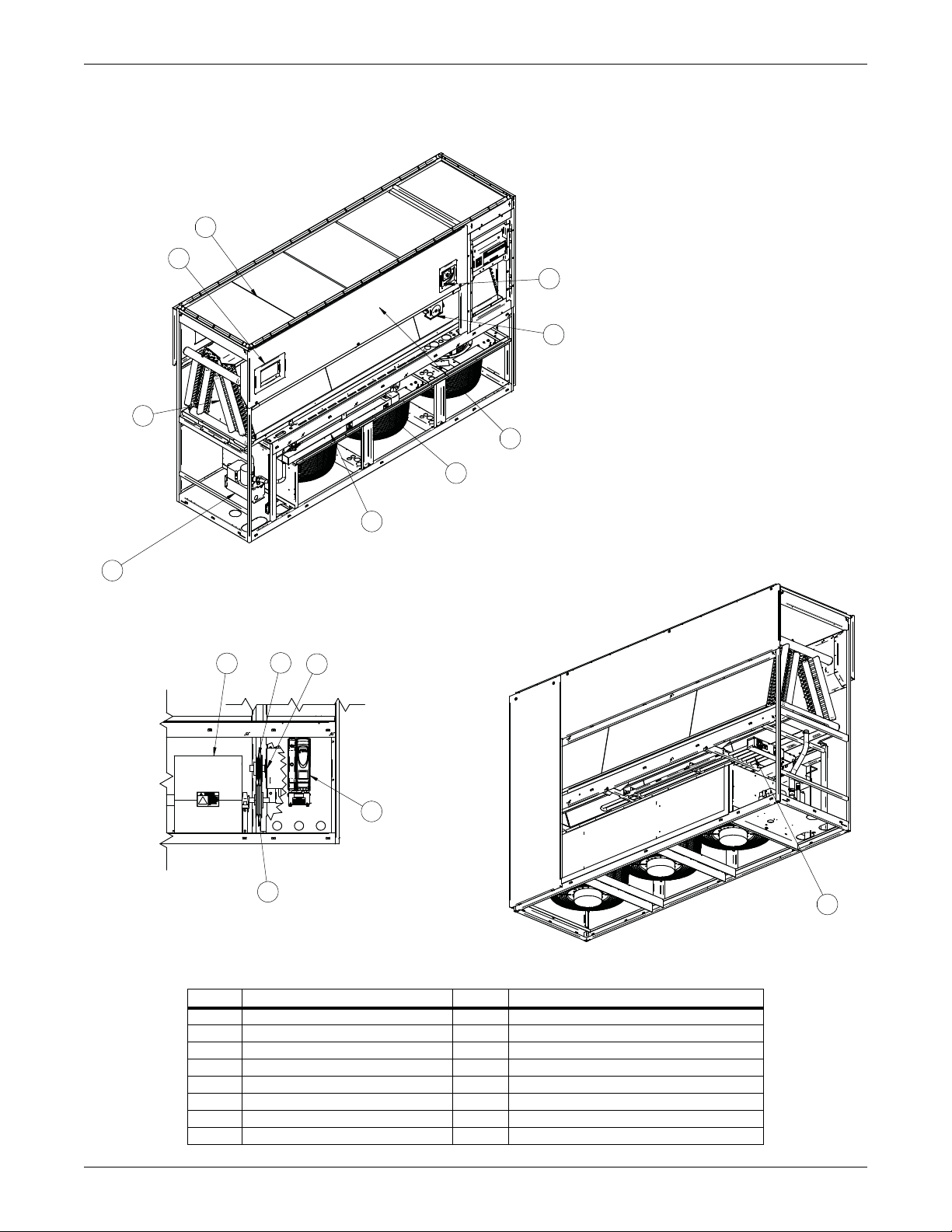
Figure 1-1 Downflow model component locations
Components
Item Description Item Description
1 iCOM control display 9 Infrared humidifier (optional)
2 Electric box 10 Reheat (optional)
3 Filters 11 Disconnect (optional)
4 Coil 12 Condensate pump (optional)
5 Motor 13 Variable-frequency drive (optional)
6Blower 14EC fans
7 Fan pulley 15 Smoke detector (optional)
8 Motor sheave and belts
3Liebert
®
CW™ System Design Manual
Page 14
Nomenclature and Components
Optional Forward-curved Blower Configuration
Front View
1
2
3
4
5
6
7
8
9
11
12
13
14
10
15
Optional EC Fan Configuration
Front View
Optional EC Fan Configuration
Rear View
Ships loose for field installation
on bottom return units.
Ships loose for
field installation
DPN002868
Rev. 1
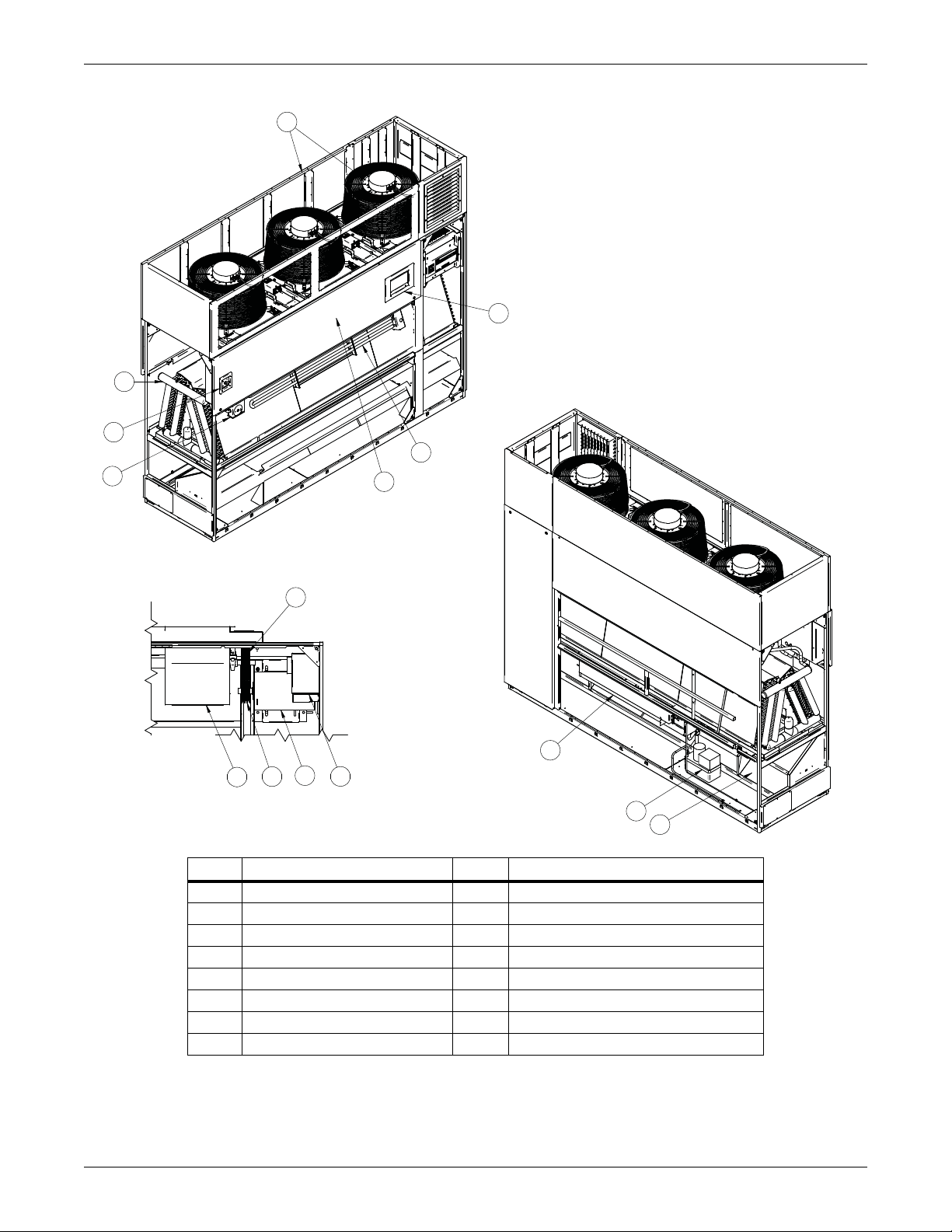
Figure 1-2 Upflow model component locations
Item Description Item Description
1 iCOM control display 9 Infrared humidifier (optional)
2 Electric box 10 Reheat (optional)
3 Filters 11 Disconnect (optional)
4 Coil 12 Condensate pump (optional)
5 Motor 13 Variable-frequency drive (optional)
6 Blower 14 Plenum with EC fans (optional)
7 Fan Pulley 15 Smoke Detector (optional)
8 Motor sheave and belts
Liebert® CW™ System Design Manual 4
Page 15
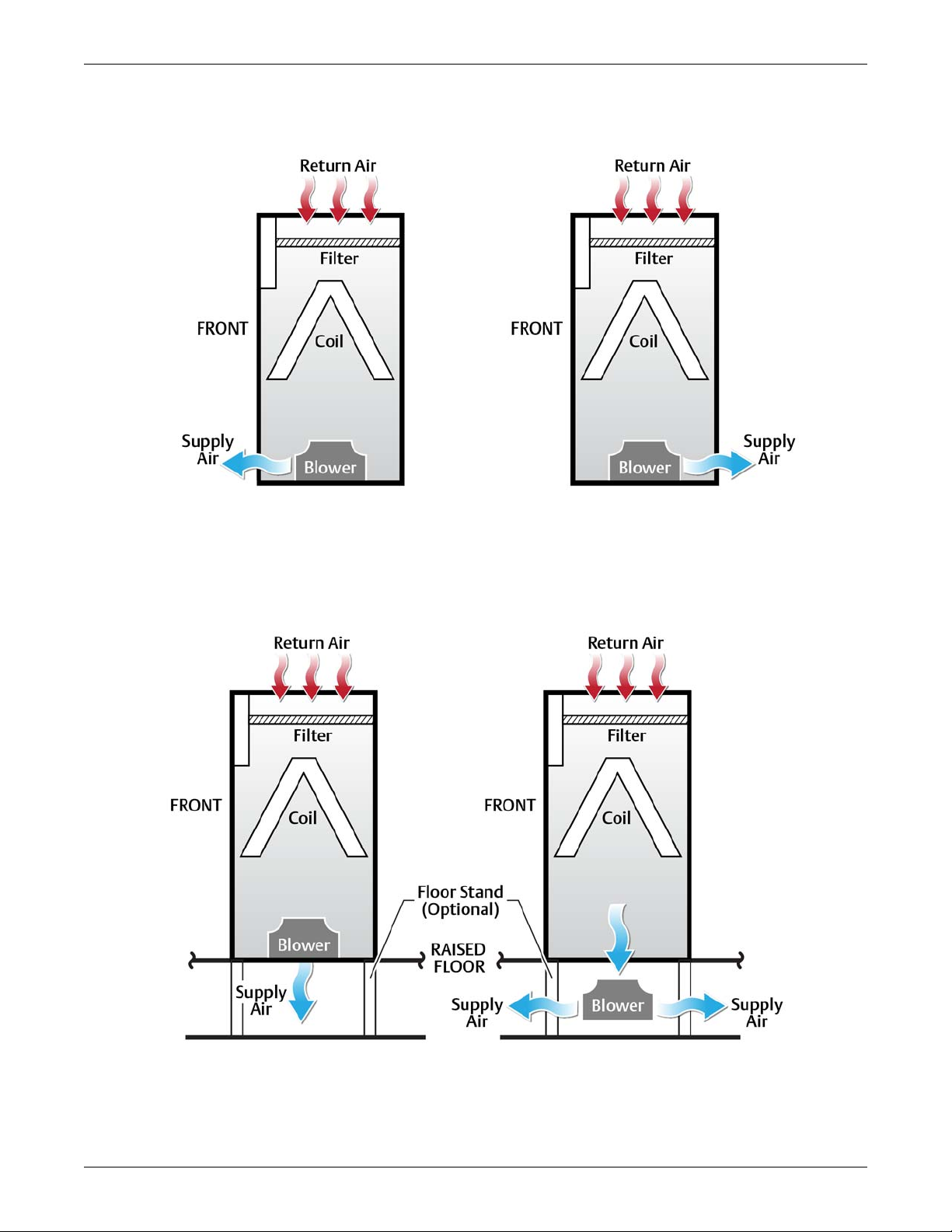
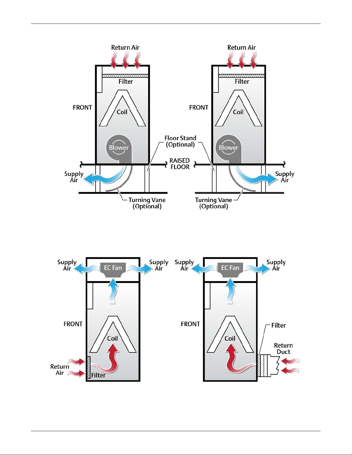
1.3 Blower Configurations
Rear Supply
Applicable to installations
without raised floors
Front Supply
Applicable to installations
without raised floors
Under-Floor Supply
(requires 24" minimum height)
Bottom Supply
Figure 1-3 Blower configurations—Downflow, front and rear supply, EC fans
Blower Configurations
Figure 1-4 Blower configurations—Downflow, bottom and under-floor supply, EC fans
5Liebert
®
CW™ System Design Manual
Page 16
Nomenclature and Components
Front Throw
Rear Throw,
Front Return
Rear Return, Ducted
Figure 1-5 Blower configurations—Downflow, under-floor supply, forward-curved blowers
Figure 1-6 Blower configurations—Upflow, EC fans in plenum
Liebert® CW™ System Design Manual 6
Page 17
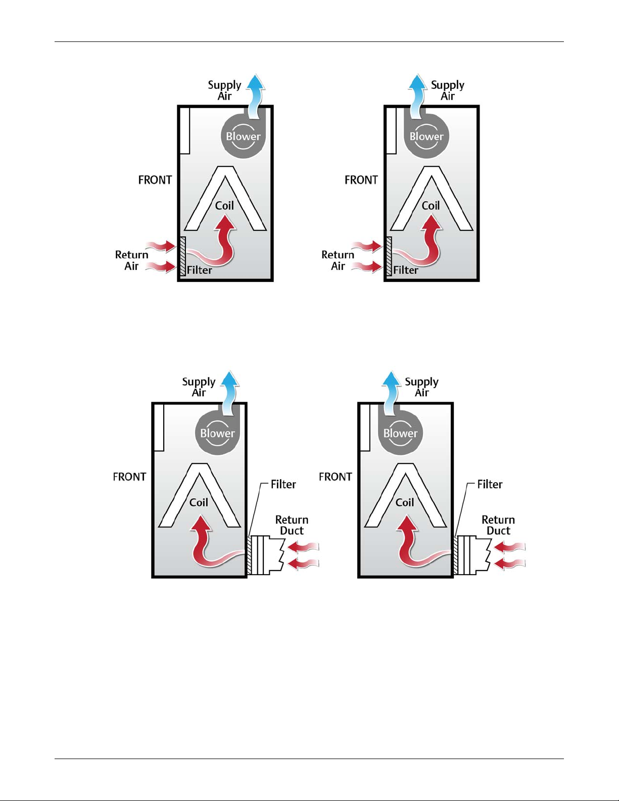
Figure 1-7 Blower configurations—Upflow, front return, forward-curved blowers
Front Throw
Rear Throw
Rear Throw,
Front Throw
Blower Configurations
Figure 1-8 Blower configurations—Upflow, rear return, forward-curved blowers
7Liebert
®
CW™ System Design Manual
Page 18

Nomenclature and Components
Page intentionally left blank.
Liebert® CW™ System Design Manual 8
Page 19

2.0 Liebert CW System Data
Table 2-1 Performance data, CW026-CW400, 50/60Hz, upflow and downflow models with EC fans
Model No. 026 038 041 051 060 076 084 089 * 106 114 146 * 181 * 300 * 400 *
CAPACITY DATA BTU/H (KW) BASED ON 45°F (7.2°C) ENTERING WATER, 10°F (5.5°C) WATER RISE
75°F DB, 61°F WB (23.9°C DB, 16.1°C WB) 45% RH
83.2
115.3
152.7
175.3
231.5
205.5
(60.2)
49.4
(3.1)
10.2
(30.5)
279.5
(81.9)
251.1
(73.6)
14.1
(42.2)
325.7
(95.4)
295.4
(86.6)
68.2
(4.3)
18.4
(55.0)
152.9
(44.8)
152.9
(44.8)
28.2
(1.8)
3.6
(10.7)
202.3
(59.3)
202.3
(59.3)
36.4
(2.3)
5.7
(17.1)
248.7
(72.9)
248.7
(72.9)
44.1
(2.80)
8.1
(24.3)
240.6
(70.50)
230.3
(67.50)
51.6
(3.3)
10.3
(30.7)
297.2
(87.1)
285.5
(83.7)
62.9
(4.0)
14.8
(44.2)
352.1
(103.2)
339.4
(99.4)
73.9
(4.7)
19.9
(59.4)
156.5
(45.9)
156.5
(45.9)
29.1
(1.8)
3.5
(10.5)
215.5
(63.1)
215.5
(63.1)
38.9
(2.5)
6.0
(17.9)
271.5
(79.5)
271.5
(79.5)
48.2
(3.0)
8.8
(26.5)
Total Capacity, kBTUH (kW)
(24.4)
(33.8)
(44.7)
(51.4)
(67.80)
Sensible Capacity, kBTUH (kW) 83.2
Flow Rate, GPM (l/s) 17.6
Pressure Drop, ft (kPA) 11.8
80°F DB, 62.8°F WB (26.7°C DB, 17.1°C WB) 38% RH
Total Capacity, kBTUH (kW) 105.5
Sensible Capacity, kBTUH (kW) 105.5
Flow Rate, GPM (l/s) 22.1
Pressure Drop, ft (kPA) 18.0
85°F DB, 64.5°F WB (29.4°C DB, 18.1°C WB) 32.3% RH
Total Capacity, kBTUH (kW) 127.2
Sensible Capacity, kBTUH (kW) 127.2
Flow Rate, GPM (l/s) 26.4
Pressure Drop, ft (kPA) 25.1
CAPACITY DATA BTU/H (KW) B ASE D ON 50° F (10 °C ) EN T ERI NG WAT ER , 12°F ( 6.66 °C ) WA TE R R IS E
75°F DB, 61°F WB (23.9°C DB, 16.1°C WB) 45% RH
Total Capacity, kBTUH (kW) 46.5
Sensible Capacity, kBTUH (kW) 46.5
Flow Rate, GPM (l/s) 8.6
Pressure Drop, ft (kPA) 3.0
80°F DB, 62.8°F WB (26.7°C DB, 17.1°C WB) 38% RH
Total Capacity, kBTUH (kW) 74.5
Sensible Capacity, kBTUH (kW) 74.5
Flow Rate, GPM (l/s) 13.3
Pressure Drop, ft (kPA) 6.7
85°F DB, 64.5°F WB (29.4°C DB, 18.1°C WB) 32.3% RH
Total Capacity, kBTUH (kW) 97.5
(28.60)
Sensible Capacity, kBTUH (kW) 97.5
(28.60)
Flow Rate, GPM (l/s) 17.1
Pressure Drop, ft (kPA) 10.8
* Models CW089, CW146, CW181, CW300 and CW400 available only in downflow.
(24.4)
(1.1)
(35.2)
(30.9)
(30.9)
(1.4)
(53.7)
(37.3)
(37.3)
(1.7)
(75.2)
(13.6)
(13.6)
(0.5)
(9.0)
(21.8)
(21.8)
(0.8)
(20.2)
(1.1)
(32.5)
113.1
(33.1)
24.6
(1.6)
18.1
(54.2)
143.0
(41.9)
140.4
(41.1)
30.1
(1.9)
26.7
(79.7)
169.9
(49.8)
167.2
(49.0)
35.5
(2.2)
36.5
(109.1)
75.3
(22.1)
75.3
(22.1)
13.9
(0.9)
6.0
(17.9)
104.7
(30.7)
104.7
(30.7)
18.7
(1.2)
10.6
(31.7)
132.5
(38.8)
132.5
(38.8)
23.4
(1.50)
16.1
(48.2)
136.6
(40.0)
32.3
(2.0)
16.4
(49.0)
183.8
(53.9)
166.6
(48.8)
38.5
(2.4)
22.6
(67.5)
213.9
(62.7)
195.7
(57.3)
44.5
(2.8)
29.4
(87.8)
102.3
(30.0)
102.3
(30)
18.5
(1.2)
5.9
(17.6)
134
(39.3)
134
(39.3)
23.8
(1.5)
9.2
(27.7)
164.2
(48.1)
164.2
(48.1)
28.8
(1.80)
13.1
(39.2)
173.6
(50.9)
37.8
(2.4)
9.3
(28.0)
219.6
(64.3)
217.3
(63.7)
46.6
(2.9)59(3.7)
13.8
(41.4)
262.4
(76.9)
259.8
(76.1)
55.2
(3.5)
19.0
(56.8)
108.3
(31.7)
108.3
(31.7)
20.4
(1.3)
2.9
(8.6)
158.6
(46.5)
158.6
(46.5)
28.8
(1.8)
5.5
(16.4)
203.6
(59.7)
203.6
(59.7)
36.2
(2.3)
8.4
(25.3)
297.2
(87.1)
264.7
77.60)
63.1
(4.0)
17.9
(53.5)
357.6
(104.8)
322.7
(94.6)
75.1
(4.70)
24.6
(73.6)
415.9
(121.9)
379.2
(111.1)
86.7
(5.5)
32.1
(95.8)
198.7
(58.2)
198.7
(58.2)
36.3
(2.3)
6.4
(19.1)
260.2
(76.2)
260.2
(76.2)
46.5
(2.9)
10.0
(30.0)
318.8
(93.4)
318.8
(93.4)
56.2
(3.6)
14.2
(42.5)
347.1
(101.7)
295.5
(86.6)
72.5
(4.6)
21.6
(64.5)
411.9
(120.70)
356.9
(104.6)
85.4
(5.4)
29.2
(87.1)
474.1
(138.9)
416.6
(122.1)
97.8
(6.2)
37.4
(111.8)
230.1
(67.4)
230.1
(67.4)
41.0
(2.6)
7.5
(22.4)
294.9
(86.4)
294.9
(86.4)
51.8
(3.3)
11.4
(34.2)
356.5
(104.5)
356.5
(104.5)
62.0
(3.9)
15.9
(47.5)
358.4
(105.0)
336.8
(98.7)
76.6
(4.8)
20.1
(60.1)
438.0
(128.3)
414.6
(121.5)
92.4
(5.8)
28.5
(85.1)
515.4
(151)
490.9
(143.8)
107.9
(6.8)
38.0
(113.4)
238.5
(69.9)
238.5
(69.9)
43.9
(2.8)
7.1
(21.2)
320.4
(93.9)
320.4
(93.9)
57.6
(3.6)
11.6
(34.8)
398.9
(116.9)
398.9
(116.9)
70.6
(4.5)
17.0
(50.7)
448.8
(131.5)
393.5
(115.3)
95.5
(6.0)
35.8
(106.9)
537.3
(157.4)
478.6
(140.2)
113.1
(7.1)
48.9
(146)
622.5
(182.4)
561.4
(164.5)
130.1
(8.2)
63.3
(189.2)
300.4
(88.0)
300.4
(88)
55.0
(3.5)
12.7
(38.0)
389.4
(114.1)
389.4
(114.1)
69.8
(4.4)
19.7
(58.9)
474.6
(139.1)
474.6
(139.1)
83.9
(5.3)
27.6
(82.6)
522.9
(153.2)
472.5
(138.4)
109.2
(6.9)
10.9
(32.5)
630.3
(184.7)
575.6
(168.7)
130.6
(8.2)
15.1
(45.2)
733.9
(215.0)
676.1
(198.1)
151.2
(9.5)
19.8
(59.2)
351.3
(102.9)
351.3
(102.9)
62.6
(4.0)
3.8
(11.5)
461.0
(135.1)
461.0
(135.1)
80.8
(5.1)
6.1
(18.3)
565.4
(165.7)
565.4
(165.7)
98.2
(6.2)
8.7
(26.2)
720.1
(211)
604.6
(177.1)
151.1
(9.5)
25.2
(75.3)
850.1
(249.1)
728.4
(213.4)
177
(11.2)
33.7
(100.6)
974.9
(285.6)
848.8
(248.7)
201.9
(12.7)
42.9
(128.1)
478.1
(140.1)
478.1
(140.1)
85.8
(5.4)
8.8
(26.4)
607.6
(178)
607.6
(178)
107.3
(6.8)
13.2
(39.6)
731.1
(214.2)
731.1
(214.2)
127.9
(8.1)
18.2
(54.4)
1003.0
(293.90)
911.4
(267.0)
209.9
(13.2)
10.1
(30.2)
1211.0
(354.8)
1112.0
(325.8)
251.3
(15.9)
14.1
(42.0)
1412.0
(413.7)
1307.0
(383.0)
291.4
(18.4)
18.5
(55.2)
672.7
(197.1)
672.7
(197.1)
120.1
(7.6)
3.5
(10.6)
885.4
(259.4)
885.4
(259.4)
155.5
(9.8)
5.7
(17.1)
1088.0
(318.8)
1088.0
(318.8)
189.2
(11.9)
8.2
(24.4)
1390.0
(407.3)
1163.0
(340.8)
292.6
(18.5)
23.8
(71.0)
1641.0
(480.8)
1402.0
(410.8)
342.6
(21.6)
31.7
(94.8)
1881.0
(551.1)
1634.0
(478.8)
390.6
(24.6)
40.3
(120.5)
920.3
(269.6)
920.3
(269.6)
166.1
(10.5)
8.3
(24.8)
1170
(342.8)
1170
(342.8)
207.6
(13.1)
12.4
(37.2)
1412.0
(413.7)
1407.0
(412.3)
247.9
(15.6)
17.2
(51.4)
9Liebert
®
CW™ System Design Manual
Page 20

Liebert CW System Data
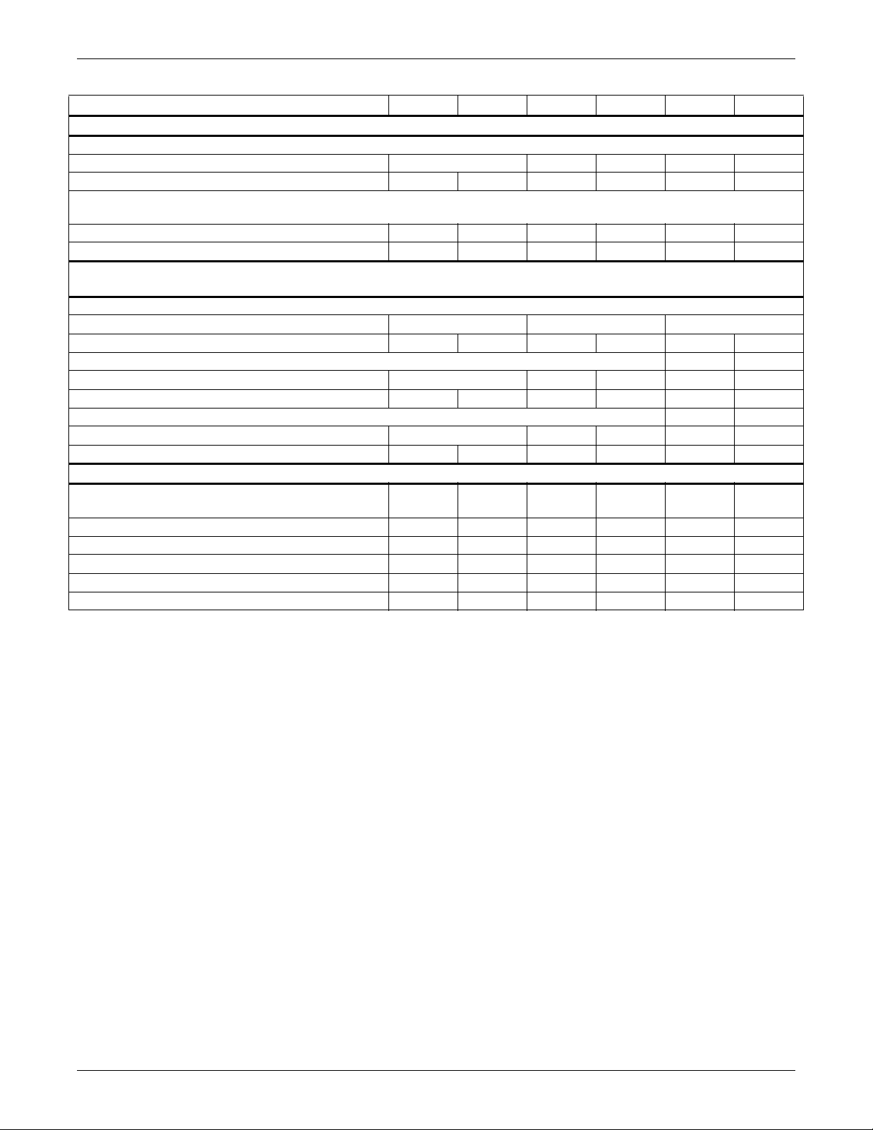
Table 2-2 Performance data, CW026-CW114, 50/60Hz, upflow and downflow models
with forward-curved blowers
Model No. 026 038 041 051 060 076 084 106 114
Capacity Data BTU/H (kW) Based on 45°F (7.2°C) Entering Water, 10°F (5.5°C) Water Rise
75°F DB, 61°F WB (23.9°C DB, 16.1°C WB) 45% RH
Total Capacity, kBTUH (kW) 77.5
(22.7)
Sensible Capacity, kBTUH (kW) 77.5
(22.7)
Flow Rate, GPM (l/s) 17.1
(1.1)
Pressure Drop, ft (kPA) 11.2
(33.4)
80°F DB, 62.8°F WB (26.7°C DB, 17.1°C WB) 38% RH
Total Capacity, kBTUH (kW) 99.2
(29.1)
Sensible Capacity, kBTUH (kW) 99.2
(29.1)
Flow Rate, GPM (l/s) 21.5
(1.4)
Pressure Drop, ft (kPA) 17.0
(51.0)
85°F DB, 64.5°F WB (29.4°C DB, 18.1°C WB) 32.3% RH
Total Capacity, kBTUH (kW) 120.4
(35.3)
Sensible Capacity, kBTUH (kW) 120.4
(35.3)
Flow Rate, GPM (l/s) 25.7
(1.6)
Pressure Drop, ft (kPA) 23.9
(71.4)
Capacity Data BTU/H (kW) Based on 50°F (10°C) Entering Water, 12°F (6.66°C) Water Rise
75°F DB, 61°F WB (23.9°C DB, 16.1°C WB) 45% RH
Total Capacity, kBTUH (kW) 41.0
(12.0)
Sensible Capacity, kBTUH (kW) 42.0
(12.0)
Flow Rate, GPM (l/s) 8.2
(0.5)
Pressure Drop, ft (kPA) 2.7
(8.3)
80°F DB, 62.8°F WB (26.7°C DB, 17.1°C WB) 38% RH
Total Capacity, kBTUH (kW) 69.1
(20.2)
Sensible Capacity, kBTUH (kW) 69.1
(20.2)
Flow Rate, GPM (l/s) 12.9
(0.8)
Pressure Drop, ft (kPA) 6.4
(19.2)
85°F DB, 64.5°F WB (29.4°C DB, 18.1°C WB) 32.3% RH
Total Capacity, kBTUH (kW) 91.5
(26.8)
Sensible Capacity, kBTUH (kW) 91.5
(26.8)
Flow Rate, GPM (l/s) 16.6
(1.1)
Pressure Drop, ft (kPA) 10.3
(30.8)
Model CW089 not available with forward-curved blowers.
107.1
(31.4)
105.1
(30.8)
24.0
(1.5)
17.3
(51.7)
133.4
(39.1)
131.9
(38.6)
29.2
(1.8)
25.2
(75.3)
159.5
(46.7)
157.9
(46.3)
34.4
(2.2)
34.5
(103.0)
68.1
(20.0)
68.1
(20.0)
13.5
(0.9)
(17.1)
96.8
(28.4)
96.8
(28.4)
18.3
(1.2)
10.1
(30.3)
124.0
(36.3)
124
(36.3)
22.8
(1.4)
15.4
(46.0)
5.7
142.8
(41.8)
128
(37.50)
31.3
(2.0)
15.5
(46.3)
172.6
(50.6)
157.0
(46.0)
37.2
(2.4)
21.3
(63.5)
201.8
(59.1)
185.4
(54.3)
43.0
(2.7)
27.7
(82.7)
94.4
(27.7)
94.4
(27.7)
18.0
(1.1)
5.6
(16.8)
125.2
(36.7)
125.2
(36.7)
23.2
(1.5)
8.8
(26.4)
154.6
(45.3)
154.6
(45.3)
28
(1.8)
12.5
(37.3)
236.7
(69.4)
152.6
(44.7)
51.2
(3.2)
16.5
(49.3)
376.1
(110.2)
192.9
(56.5)
79.0
(5.0)
37.4
(111.7)
524.1
(153.6)
228.8
(67.0)
108.5
(6.8)
68.2
(203.7)
101.8
(29.8)
101.8
(29.8)
20.3
(1.3)
2.8
(8.5)
152.1
(44.6)
152.1
(44.6)
28.6
(1.8)
5.4
(16.3)
196.9
(57.7)
196.9
(57.7)
36.1
(2.3)
8.4
(25.1)
229.5
(67.2)
203.4
(59.6)
49.9
(3.2)
10.4
(31)
278.1
(81.5)
249.5
(73.1)
59.6
(3.8)
14.3
(42.9)
324.7
(95.1)
294.3
(86.2)
68.8
(4.3)
18.7
(56.0)
150.3
(44.0)
150.3
(44.0)
28.5
(1.8)
3.6
(10.9)
200.1
(58.6)
200.1
(58.6)
36.7
(2.3)
5.8
(17.4)
247.1
(72.4)
247.1
(72.4)
44.6
(2.8)
8.2
(24.7)
231.6
(67.9)
221.4
(64.9)
51.9
(3.3)
10.4
(31.1)
288.6
(84.6)
276.9
(81.1)
63.3
(4.0)
14.9
(44.6)
343.8
(100.7)
331.2
(97.0)
74.3
(4.7)
20.1
(60.1)
147.0
(43.1)
147
(43.1)
29.3
(1.8)
3.5
(10.6)
206.4
(60.5)
206.4
(60.5)
39.1
(2.5)
6.0
(18.1)
262.7
(77)
262.7
(77.0)
48.5
(3.1)
9.0
(26.8)
290.6
(85.1)
258
(75.6)
63.7
(4.0)
18.2
(54.5)
351.7
(103.0)
316.7
(92.8)
75.9
(4.8)
25.1
(75.0)
410.6
(120.3)
373.8
(109.5)
87.6
(5.5)
32.7
(97.6)
191.2
(56)
191.2
(56.0)
36.6
(2.3)
6.5
(19.5)
253.4
(74.2)
253.4
(74.2)
47.0
(3.0)
10.2
(30.6)
312.6
(91.6)
312.6
(91.6)
56.8
(3.6)
14.5
(43.3)
345.0
(101.1)
323.4
(94.8)
76.1
(4.8)
19.9
(59.4)
424.1
(124.3)
400.7
(117.4)
91.8
(5.8)
28.1
(84.1)
501.0
(146.8)
476.4
(139.6)
107.2
(6.8)
37.5
(112)
225.8
(66.2)
225.8
(66.2)
43.7
(2.8)
7.0
(20.9)
307.2
(90.0)
307.2
(90.0)
57.2
(3.6)
11.5
(34.3)
385.2
(112.9)
385.2
(112.9)
70.2
(4.4)
16.7
(50.1)
427.8
(125.3)
371.4
(108.8)
92.7
(5.9)
33.9
(101.2)
513.0
(150.3)
453.1
(132.8)
109.7
(6.9)
46.2
(138)
595
(174.3)
532.7
(156.1)
126.0
(8.0)
59.7
(178.3)
281.8
(82.6)
281.8
(82.6)
53.1
(3.4)
11.9
(35.7)
367.4
(107.6)
367.4
(107.6)
67.3
(4.2)
18.4
(55.1)
449.3
(131.6)
449.3
(131.6)
80.9
(5.1)
25.8
(77.2)
Liebert® CW™ System Design Manual 10
Page 21

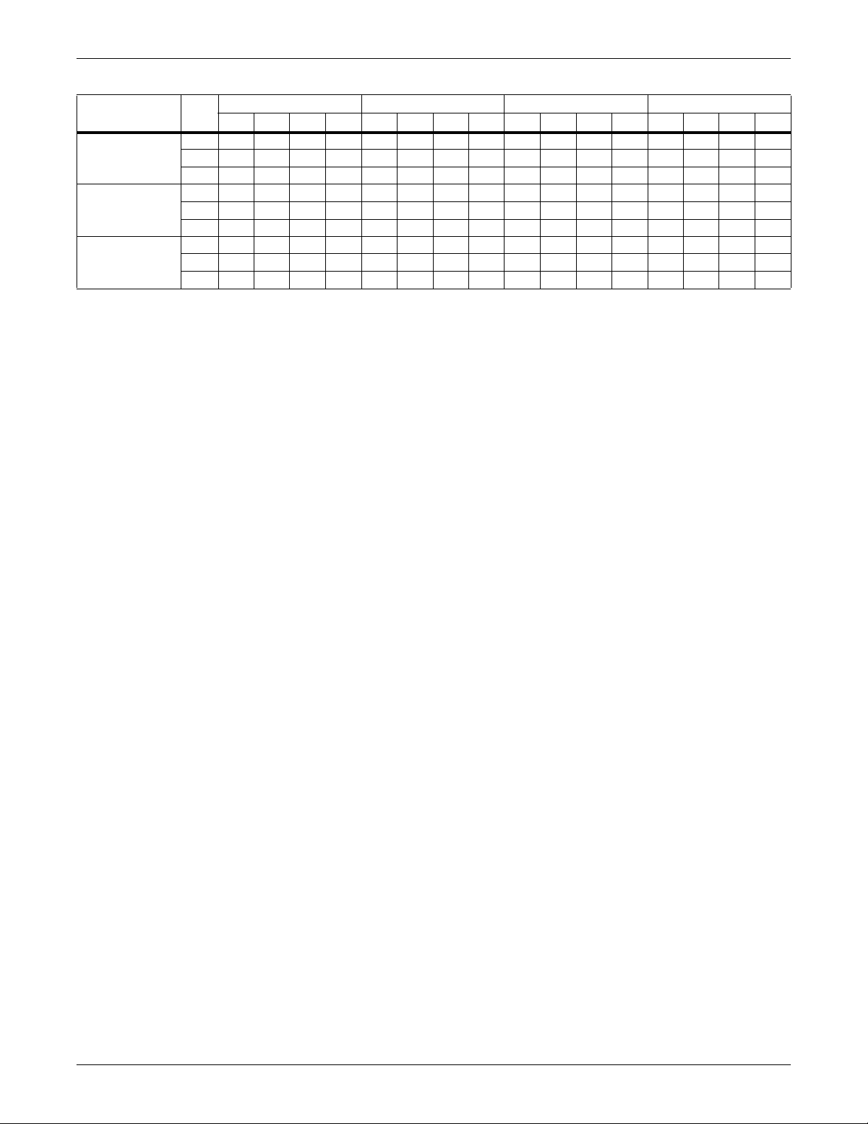
Table 2-3 Performance data for select Liebert CW Units with EC fans, High Delta T conditions
Entering
Water
Return Air Conditions of 80°F DB, 62.8°F WB, 52.3°F Dew Point (26.6°C DB, 17.1°C WB) 38.1% RH
14°F (7.8°C)
Water Rise
16°F (8.9°C)
Water Rise
Return Air Conditions of 85°F DB, 64.5°F WB, 52.3°F Dew Point (29.4°C DB, 18.1°C WB) 32.4% RH
14°F (7.8°C)
Water Rise
16°F (8.9°C)
Water Rise
Return Air Conditions of 90°F DB, 66.1°F WB, 52.3°F Dew Point (32.2°C DB, 18.9°C WB) 27.6% RH
14°F (7.8°C)
Water Rise
16°F (8.9°C)
Water Rise
Liebert CW Model
Numbers CW106 CW114 CW146 CW181 CW300 CW400
CAPACITY DATA BTU/HR (KW) BASED ON 50°F (10°C) ENTERING WATER, 0.2" ESP WITH ASHRAE 127-2012 STANDARD
Total, kBTUH (kW)
Sensible, kBTUH (kW)
Flow Rate, GPM (l/s)
Press. Drop, ft (kPa)
Total, kBTUH (kW)
Sensible, kBTUH (kW)
Flow Rate, GPM (l/s)
Press. Drop, ft (kPa)
CAPACITY DATA BTU/HR (KW) BASED ON 50°F (10°C) ENTERING WATER, 0.2" ESP WITH ASHRAE 127-2012 STANDARD
Total, kBTUH (kW)
Sensible, kBTUH (kW)
Flow Rate, GPM (l/s)
Press. Drop, ft (kPa)
Total, kBTUH (kW)
Sensible, kBTUH (kW)
Flow Rate, GPM (l/s)
Press. Drop, ft (kPa)
CAPACITY DATA BTU/HR (KW) BASED ON 50°F (10°C) ENTERING WATER, 0.2" ESP WITH ASHRAE 127-2012 STANDARD
Total, kBTUH (kW)
Sensible, kBTUH (kW)
Flow Rate, GPM (l/s)
Press. Drop,- ft (kPa)
Total, kBTUH (kW)
Sensible, kBTUH (kW)
Flow Rate, GPM (l/s)
Press. Drop, ft (kPa)
301.6 (88.3) 376.7 (110.3) 439.2 (128.6) 588.8 (172.4) 797.1 (233.4) 1054.6 (308.8)
301.6 (88.3) 376.7 (110.3) 439.2 (128.6) 588.8 (172.4) 797.1 (233.4) 1054.6 (308.8)
46.6 (2.9) 58.0 (3.7) 66.1 (4.2) 89.3 (5.6) 120.8 (7.6) 161.6 (10.2)
7.8 (23.3) 14.0 (41.8) 4.2 (12.6) 9.4 (28.1) 3.6 (10.8) 7.9 (23.6)
273.9 (80.2) 353.5 (103.5) 405.0 (118.6) 560.1 (164.0) 733.2 (214.7) 1004.7 (294.2)
273.9 (80.2) 353.5 (103.5) 405.0 (118.6) 560.1 (164.0) 733.2 (214.7) 1004.7 (294.2)
37.4 (2.4) 47.8 (3.0) 53.6 (3.4) 74.6 (4.7) 97.8 (6.2) 135.1 (8.5)
5.2 (15.5) 9.8 (29.3) 2.9 (8.7) 6.8 (20.3) 2.4 (7.2) 5.7 (17.0)
383.9 (112.4) 466.2 (136.5) 548.8 (160.7) 717.2 (210.0) 998.9 (292.5) 1284.8 (376.2)
383.9 (112.4) 466.2 (136.5) 548.8 (160.7) 717.2 (210.0) 998.9 (292.5) 1284.8 (376.2)
58.3 (3.7) 70.7 (4.5) 81.8 (5.2) 107.6 (6.8) 149.5 (9.4) 194.4 (12.3)
11.9 (35.6) 20.1 (60.1) 6.2 (18.5) 13.2 (39.5) 5.3 (15.8) 11.0 (32.9)
359.3 (105.2) 446.0 (130.6) 519.4 (152.1) 692.9 (202.9) 944.3 (276.5) 1242.8 (363.9)
359.3 (105.2) 446.0 (130.6) 519.4 (152.1) 692.9 (202.9) 944.3 (276.5) 1242.8 (363.9)
48.0 (3.0) 59.3 (3.7) 67.9 (4.3) 91.1 (5.7) 124.1 (7.8) 164.9 (10.4)
8.3 (24.8) 14.5 (43.3) 4.4 (13.2) 9.8 (29.3) 3.7 (11.1) 8.1 (24.2)
463.1 (135.6) 552.2 (161.7) 654.0 (191.5) 840.5 (246.1) 1192.9 (349.3) 1506.1 (441.0)
463.1 (135.6) 552.2 (161.7) 654.0 (191.5) 840.5 (246.1) 1192.9 (349.3) 1506.1 (441.0)
69.6 (4.4) 83.0 (5.2) 96.7 (6.1) 125.1 (7.9) 177.1 (11.2) 225.8 (14.2)
16.5 (49.3) 27.0 (80.7) 8.5 (25.4) 17.4 (52.0) 7.2 (21.5) 14.5 (43.3)
440.6 (129.0) 533.8 (156.3) 627.4 (183.7) 819.3 (239.9) 1142.7 (334.6) 1469.9 (430.4)
440.6 (129.0) 533.8 (156.3) 627.4 (183.7) 819.3 (239.9) 1142.7 (334.6) 1469.9 (430.4)
58.1 (3.7) 70.3 (4.4) 81.3 (5.1) 106.9 (6.7) 148.8 (9.4) 193.1 (12.2)
11.7 (35.0) 19.8 (59.2) 6.1 (18.2) 13.0 (38.9) 5.2 (15.5) 10.8 (32.3)
11 Liebert® CW™ System Design Manual
Page 22
Liebert CW System Data
Table 2-4 Motor size required to deliver rated airflow, models with forward-curved blowers
External Static
Model
026 5050 (2383) 3555555
038 5850 (2761) 5 5 5 — — —
041 5750 (2714) 5 ——————
051 9150 (4318) 7.5 7.5 —————
060 8900 (4200) 7.5 7.5 —————
076 12100 (5711) 10 15 15 15 15 — —
084 11650 (5498) 10 15 15 15 15 — —
106 17100 (8070) 15 15 15 15 15 — —
114 16500 (7787) 15 15 15 15 — — —
* Delivered airflow is less than rated airflow
Table 2-5 Maximum airflow with maximum motor size at listed static pressure,
External Static
Pressure 0.2" 0.4" 0.6" 0.8" 1.0" 1.2" 1.4"
Model
026
038
041
051
060
076
084
106
114
Pressure 0.2" 0.4" 0.6" 0.8" 1.0" 1.2" 1.4"
Rated Airflow
CFM (l/s) Motor Size, hp
models with forward-curved blowers
Rated
Airflow
CFM (l/s) Airflow, CFM (l/s)
5050
(2383)
5850
(2761)
5750
(2714)
9150
(4318)
8900
(4200)
12100
(5711)
11650
(5498)
17100
(8070)
16500
(7787)
5050
(2383)
5850
(2761)
5750
(2714)
9150
(4318)
8900
(4200)
12100
(5711)
11650
(5498)
17100
(8070)
16500
(7787)
5050
(2383)
5850
(2761)
5750
(2714)
9150
(4318)
8900
(4200)
12100
(5711)
11650
(5498)
17100
(8070)
16500
(7787)
5050
(2383)
5850
(2761)
5600
(2643)
9100
(4295)
8750
(4130)
12100
(5711)
11650
(5498)
17100
(8070)
16500
(7787)
5050
(2383)
5750
(2714)
5450
(2572)
8900
(4200)
8550
(4035)
12100
(5711)
11650
(5498)
17100
(8070)
16500
(7787)
5050
(2383)
5600
(2643)
5350
(2525)
8700
(4106)
8400
(3964)
12100
(5711)
11650
(5498)
17100
(8070)
16100 — —
5050
(2383)
5450
(2572)
——
8550
(4035)
8200
(3870)
11600
(5475)
11400
(5380)
16400
(7740)
5050
(2383)
5350
(2525)
8350
(3941)
8050
(3799)
11000
(5191)
NA
16100
(7598)
Liebert® CW™ System Design Manual 12
Page 23

Table 2-6 Physical data, Liebert CW026 - CW089, 50/60Hz models
Model Sizes 026 038 041 051 060 076 084 089
FAN SECTION
Some options or combinations of options may result in reduced airflow. Consult your sales representative for recommendations.
Fan Data - EC Fans - Available in Upflow and Downflow Orientations (CW089 available in downflow only)
Nominal Air Volume, CFM (CMH) 5,250
(8,925)
Fan Motor, Maximum hp (kW),
Fan Motor, Max hp (kW),
Standard Ext Static Pressure, inches of
Fan Data - Forward-curved Blowers - Variable Pitch, Two-Belt Drive Package - Available in Upflow and Downflow* Configurations
Fan Motor, Maximum hp (kW), each 3.0 (2.2) 5.0 (3.7) 7.5 (5.6) 10.0 (7.5)
Standard Ext Static Pressure, inches of
Face Velocity, EC Fans, FPM (m/s) 450
Chilled Water Valves (Standard valves, Maximum design water pressure 150 PSI[1034.3 kPA]. Higher pressure available as an option.
Consult your sales representative for information).
Valve Actuator, Sensors, and Body Modulating Valve Actuator with Proportional Sensors and either
2-Way Valve (Opt) Close-off Pressure,
Electric Reheat - Three Stage, Fin/Tube
Steam Reheat: 218°F (103.3°C)
Steam, 75°F (23.9°C) EAT
Hot Water Reheat @ 180°F (82.2°C)
EWT & 75°F (23.8°C) EAT
Pressure Drop, PSI (kPA) 3.5 (24.1) 1.6 (11.0) 1.6 (11.0)
Downflow, each
4.0 (3.0) 4.0 (3.0) 4.0 (3.0)
Upflow, each
water (PA)
Number of Fans 1 1 1 2 2 2 2 2
Nominal Air Volume,
CFM (CMH)
water (PA)
Number of Fans 1 1 1 2 2 2 2 2
Face Area, ft
Number of Rows 3 4 6 4 6 4 6 6
Valve CV 11.6 11.6 28.9 28.9 46.2 46.2 46.2 46.2
Valve Size, in. 1 1-1/4 1-1/2 1-1/2 2 2 2 2
PSI (kPA)
Capacity, BTU/HR (kW) 34,130 (10) 51,195 (15) 68,260 (20) 83,325 (25) 102,390 (30)
Capacity, BTU/HR (kW) 85,800
Capacity, BTU/HR (kW) 47,000
Flow Rate, GPM (l/s) 5 (0.31) 5 (0.31) 5 (0.31) 8 (0.50) 8 (0.50) 8 (0.50) 8 (0.50) N/A
4.0 (3.0) 4.0 (3.0) 4.0 (3.0) 4.0 (3.0) 4.0 (3.0) 4.0 (3.0) 4.0 (3.0) 4.0 (3.0)
0.2 (50) 0.2 (50) 0.2 (50) 0.2 (50) 0.2 (50) 0.2 (50) 0.2 (50) 0.2 (50)
5,050
(8,580)
0.2 (50) 0.2 (50) 0.2 (50) 0.2 (50) 0.2 (50) 0.2 (50) 0.2 (50) 0.2 (50)
2
(m2)
(2.28)
(25.1)
(13.7)
6,050
(10,285)
5,850
(9,940)
11.7 (1.1) 18.5 (1.7) 25.0 (2.3) 36.3 (3.4)
519
(2.63)
86 (593) 70 (483) 45 (310) 45 (310)
85,800
(25.1)
49,500
(14.5)
5,950
(10,115)
5,750
(9,770)
CHILLED WATER COIL
(2.59)
REHEAT SECTION
Modulating 2-way, 150 PSI (1034.3 kPa) max operating pressure.
Unit CFM reduced by 300 with standard motor (142 l/s)
85,800
(25.1)
Modulating 2-way, 150 PSI (1034.3 kPa) max operating pressure.
Unit CFM reduced by 300 with standard motor (142 l/s)
49,500
(14.5)
9,200 (15,640) 9,200 (15,640)
3.6
for 208/230 V
3.4
for 380 to 460V,
60 Hz/50 Hz
9,150
15,550
510
503
(2.55)
2-Way or 3-Way Valve Body
Not applicable to units with EC fans.
93,400 (27.4) 144,500 (42.4)
Not applicable to units with EC fans.
89,900 (26.3) 89,900 (26.3)
for 208/230 V
for 380 to 460V,
60 Hz/50 Hz
3.6
3.4
8,900
(15,120)
503
(2.55)
12,400
(21,080)
4.0 (3.0) 4.0 (3.0) 4.0 (3.0)
12,100
(20,560)
496
(2.51)
163,200
(47.8)
125,200
(36.7)
11,900
(20,230)
11,650
(19,790)
476
(2.41)
163,200
(47.8)
125,200
(36.7)
12,100
(20,570)
(1.69)
N/A
333
N/A
N/A
13 Liebert® CW™ System Design Manual
Page 24
Liebert CW System Data
Table 2-6 Physical data, Liebert CW026 - CW089, 50/60Hz models (continued)
Model Sizes 026 038 041 051 060 076 084 089
HUMIDIFIER SECTION
Infrared Humidifier
Capacity, lb/hr (kg/h) 1 1 (5.0) 11 (5.0) 11 (5.0) 17.4 (7.9) 17.4 (7.9) 22.1 (10) 22.1 (10) 22.1 (10)
kW 4.8 4.8 4.8 6.4 6.4 9.6 9.6 9.6
Steam Generating Humidifier,
Not applicable to units with EC fans. (Water Conductivity between 200-500 micro-ohms is required for ideal operation)
Capacity, lb/hr (kg/h) 11 (5.0) 22 (10.0) N/A
kW 3.6 3.6 3.6 7.2 7.2 7.2 7.2 7.2
Steam Grid Humidifier - All Models (Standard Selection, 5 PSIG (34.5 kPa), Steam 14 lb/hr. [6.4 kg/h])
Supply Steam Pressure, PSIG (kPa) — 2 (13.8) 4 (27.6) 5 (34.5) 6 (41.4) 8 (55.2) 10 (68.9) N/A
Capacity, lb/hr (kg/h), w/ 5/32” orifice — 8 (3.6) 12 (5.4) 14 (6.4) 16 (7.3) 19 (8.6) 21 (9.5) N/A
FILTER SECTION
Disposable Type - Nominal Size and Quantities, MERV8 and MERV11 (option)
Downflow Models
Nominal Size, in 18 x 24 24 x 31
Quantity 4 4 4 6 6 8 8 5
Upflow Models (Front Return)
Nominal Size, in 24 x 24 N/A
Quantity 2 2 2 3 3 4 4 N/A
Upflow Models (Bottom and Rear Return)
Nominal Size, in 18 x 24 N/A
Quantity 4 4 4 6 6 8 8 N/A
CONNECTION SIZES
Chilled Water, OD Copper 1-1/8 1-3/8 1-5/8 1-5/8 2-1/8 2-1/8 2-1/8 2-5/8
Infrared Humidifier, OD Copper 1/4 1/4 1/4 1/4 1/4 1/4 1/4 1/4
Condensate Drain, FPT 3/4 3/4 3/4 3/4 3/4 3/4 3/4 1-1/4
Steam Reheat, MPT, FC Blower only 1/2 1/2 1/2 1/2 3/4 3/4 3/4 N/A
Hot Water Reheat, OD Copper, FC
Blower only
Steam Grid Humidifier, MPT, FC
Blower only
5/8 5/8 5/8 7/8 7/8 7/8 7/8 N/A
1/2 1/2 1/2 1/2 1/2 1/2 1/2 N/A
Liebert® CW™ System Design Manual 14
Page 25
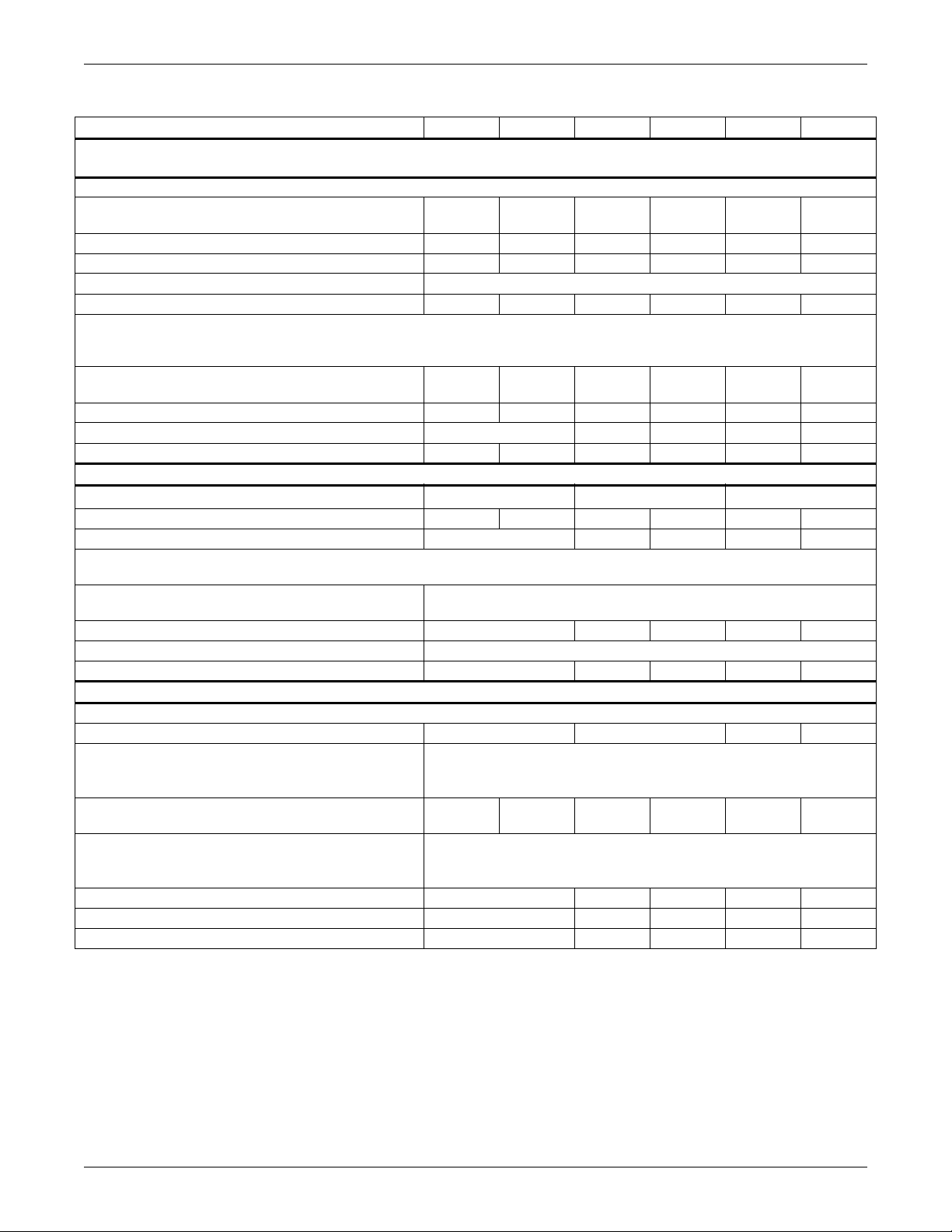
Table 2-7 Physical data—Liebert CW106 - CW400, 50/60Hz models
Model Sizes 106 114 146 181 300 400
FAN SECTION
Some options or combinations of options may result in reduced airflow. Consult your Emerson representative for recommendations.
Fan Data - EC Fans - CW106 & CW114 are available in Upflow and Downflow Orientations. CW146 to CW400 are available in Downflow only.
Nominal Air Volume, CFM (CMH) 17,300
(29,410)
Fan Motor, Maximum hp (kW), Downflow, each 4.0 (3.0) 4.0 (3.0) 3.7 (2.8) 4.9 (3.7) 4.2 (3.4) 5.4 (4.4)
Fan Motor, Maximum hp (kW), Upflow, each 4.0 (3.0) 4.0 (3.0) — — — —
Standard Ext Static Pressure, inches of water (PA) 0.2 (50)
Number of Fans 3 3 3 3 6 6
Fan Data -Forward-curved Blowers - Variable Pitch, Two-Belt Drive Package CW106 & CW114 are available in Upflow and Downflow Orientations.
CW146 to CW400 are available with EC Fans in downflow orientation only.
Nominal Air Volume, CFM (CMH) 17,100
(29,050)
Fan Motor, Maximum hp (kW), each 3.0 (2.2) 5.0 (3.7) — — — —
Standard Ext Static Pressure, inches of water (PA) 0.2 (50) — — — —
Number of Fans 3 3 — — — —
CHILLED WATER COIL
2
Face Area, ft
Number of Rows464646
Face Velocity, EC Fans, FPM (m/s) 476 (1.34) 373 (1.89) 427 (2.16) 359 (1.82) 406 (2.06)
Chilled Water Valves (Standard valves, Maximum design water pressure 150 PSI [1034.3 kPA]. Higher pressure available as an option. Consult
your Emerson representative for information).
Valve Actuator, Sensors, & Body Modulating Valve Actuator with Proportional Sensors and
Valve Size, in. 2
2-Way Valve (Opt) Close-off Pressure, PSI (kPA) 45 (310) 200 (1,378) 200 (1,378) 200 ( 1,378) 200 (1,378)
Electric Reheat - Three-Stage, Fin Tube
Capacity, BTU/HR (kW) 102,390 (30) 102,390 (30) — —
Steam Reheat: 218°F (103.3°C) Steam, 75°F (23.9) EAT Modulating 2-way, 150 PSI (1034.3 kPa) maximum operating
Capacity, BTU/HR (kW) 84,100
Hot Water Reheat @ 180°F (82.2°C) EWT 75°F (23.8°C) EAT Modulating 2-way, 150 PSI (1034.3 kPa) maximum operating pressure.
Capacity, BTU/HR (kW) 133,700 (39.2) — — — —
Flow Rate, GPM (l/s) 8 (0.50) — — — —
Pressure Drop, PSI (kPA) 1.6 (11.0) — — — —
(m2)
Valve CV 46.2 46.2; qty 2 46.2; qty 2 46.2; qty 4 46.2; qty 4
REHEAT SECTION
(24.6)
17,300
(29,410)
16,500
(28,030)
36.3 (3.4) 56.3 (5.3) 112.6 (10.6)
pressure. Not applicable to units with EC fans.
Unit CFM reduced by 300 with standard motor (142 l/s)
85,800
(25.1)
Unit CFM reduced by 300 with standard motor (142 l/s)
21,000
(35,700)
————
either 2-Way or 3-Way Valve Body
————
Not applicable to units with EC fans.
24,000
(40,800)
40,500
(68,850)
45,700
(77690)
15 Liebert® CW™ System Design Manual
Page 26
Liebert CW System Data
Table 2-7 Physical data—Liebert CW106 - CW400, 50/60Hz models (continued)
Model Sizes 106 114 146 181 300 400
HUMIDIFIER SECTION
Infrared Humidifier Note (50Hz Models are 22.1 lb/h (10.0 kg/h); 9.6 kW)
Capacity, lb/hr (kg/h) 22.1 (10) 22.1 (10) 22.1 (10) — —
kW 9.6 9.6 9.6 9.6 — —
Steam Generating Humidifier (Water Conductivity between 200-500 micro-ohms is required for ideal operation) - Not applicable to units with EC
fans.
Capacity, lb/hr (kg/h) 22 (10.0) 22 (10.0) — — — —
kW9.69.6————
FILTER SECTION
Disposable Type - Nominal Size and Quantities, MERV8 and MERV11 (option)
Downflow Models
Nominal Size, in 24 x 31 21.5 x 24 29.5 x 28.5
Quantity 5 5 10 10 12 12
Upflow Models (Front Return)
Nominal Size, in 18 x 24 N/A N/A N/A N/A
Quantity 2 2 N/A N/A N/A N/A
Upflow Models (Bottom & Rear Return)
Nominal Size, in 18 x 24 N/A N/A N/A N/A
Quantity 10 10 N/A N/A N/A N/A
CONNECTION SIZES
Chilled Water, OD Copper
Infrared Humidifier, OD Copper 1/4” 1/4” 1/4” 1/4” N/A N/A
Condensate Drain, FPT 1-1/4” 1-1/4” 1-1/4” 1-1/4” 1-1/4” 1-1/4”
Steam Reheat, MPT 3/4” 3/4” N/A N/A N/A N/A
Hot Water Reheat, OD Copper 7/8” 7/8” N/A N/A N/A N/A
Steam Humidifier, MPT 1/2” 1/2” N/A N/A N/A N/A
2-1/8” 2-5/8” 3-1/8” 3-1/8”
3-1/8”
(qty 2)
3-1/8”
(qty 2)
Liebert® CW™ System Design Manual 16
Page 27

3.0 Electrical Data
Table 3-1 Electrical data, Liebert CW with EC fans, 60Hz
Reheat/Humidifier No Reheat/Humidifier Reheat/No Humid ifier No Reheat/No Humidifier
Models Volts
CW026
CW038
CW041
CW051
Downflow
CW051
Upflow
CW060
Downflow
CW060
Upflow
CW076
CW084
CW089
Downflow
CW106
CW114
CW146
Downflow
CW181
Downflow
CW300
Downflow
CW400
Downflow
208 230 380 460 575 208 230 380 460 575 208 230 380 460 575 208 230 380 460 575
FLA 50.3 46.5 24.7 23.0 20.6 22.5 20.3 11.0 9.8 10.6 37.0 35.4 18.6 17.2 13.2 9.2 9.2 4.9 4.0 3.2
WSA 62.9 58.1 30.9 28.8 25.8 28.1 25.4 13.8 12.3 13.3 46.3 44.3 23.3 21.5 16.5 11.5 11.5 6.1 5.0 4.0
OPD70 60 3530303030151515 45 45 2020152020151515
FLA 64.1 59.4 31.6 29.5 25.7 22.5 20.3 11.0 9.8 10.6 50.8 48.3 25.5 23.7 18.3 9.2 9.2 4.9 4.0 3.2
WSA 80.1 74.3 39.5 36.9 32.1 28.1 25.4 13.8 12.3 13.3 63.5 60.4 31.9 29.6 22.9 11.5 11.5 6.1 5.0 4.0
OPD90 80 4040353030151515 70 70 3530252020151515
FLA 64.1 59.4 31.6 29.5 25.7 22.5 20.3 11.0 9.8 10.6 50.8 48.3 25.5 23.7 18.3 9.2 9.2 4.9 4.0 3.2
WSA 80.1 74.3 39.5 36.9 32.1 28.1 25.4 13.8 12.3 13.3 63.5 60.4 31.9 29.6 22.9 11.5 11.5 6.1 5.0 4.0
OPD90 80 4040353030151515 70 70 3530252020151515
FLA 98.7 91.3 47.4 45.3 — 43.2 38.8 20.0 19.1 — 72.1 69.1 35.2 32.4 — 16.6 16.6 7.8 6.2 —
WSA 123.4 114.1 59.3 56.6 — 54.0 48.5 25.0 23.9 — 90.1 86.4 44.0 40.5 — 18.7 18.7 8.8 7.0 —
OPD 125 125 60 60 — 60 45 30 25 — 100 90 45 45 — 20 20 15 15 —
FLA 100.5 93.1 49.4 47.1 40.0 45.0 40.6 22.0 20.9 19.9 73.9 70.9 37.2 34.2 26.5 18.4 18.4 9.8 8.0 6.4
WSA 125.6 116.4 61.8 58.9 50.0 56.3 50.8 27.5 26.1 24.9 92.4 88.6 46.5 42.8 33.1 20.7 20.7 11.0 9.0 7.2
OPD 150 125 70 60 60 50 50 25 30 25 100 90 50 45 35 25 25 15 15 15
FLA 112.6 104.3 54.3 51.8 — 43.2 38.8 20.0 19.1 — 86.0 82.1 42.1 38.9 — 16.6 16.6 7.8 6.2 —
WSA 140.8 130.4 67.9 64.8 — 54.0 48.5 25.0 23.9 — 107.5 102.6 52.6 48.6 — 18.7 18.7 8.8 7.0 —
OPD 150 150 70 70 — 60 45 30 25 — 110 110 60 50 — 25 25 15 15 —
FLA 114.4 106.1 56.3 53.6 45.0 45.0 40.6 22.0 20.9 19.9 87.8 83.9 44.1 40.7 31.5 18.4 18.4 9.8 8.0 6.4
WSA 143.0 132.6 70.4 67.0 56.3 56.3 50.8 27.5 26.1 24.9 109.8 104.9 55.1 50.9 39.4 20.7 20.7 11.0 9.0 7.2
OPD 150 150 80 70 60 50 50 25 30 25 110 110 60 60 40 25 25 15 15 15
FLA 124.1 119.2 63.1 58.7 48.1 45.0 40.6 22.0 19.6 18.0 97.5 97.0 50.9 47.1 36.5 18.4 18.4 9.8 8.0 6.4
WSA 155.1 149.0 78.9 73.4 60.1 56.3 50.8 27.5 24.5 22.5 121.9 121.3 63.6 58.9 45.6 20.7 20.7 11.0 9.0 7.2
OPD 175 150 80 80 70 50 50 25 20 25 125 125 70 60 50 25 25 15 15 15
FLA 124.1 119.2 63.1 58.7 48.1 45.0 40.6 22.0 19.6 18.0 97.5 97.0 50.9 47.1 36.5 18.4 18.4 9.8 8.0 6.4
WSA 155.1 149.0 78.9 73.4 60.1 56.3 50.8 27.5 24.5 22.5 121.9 121.3 63.6 58.9 45.6 20.7 20.7 11.0 9.0 7.2
OPD 175 150 80 80 70 50 50 25 20 25 125 125 70 60 50 25 25 15 15 15
FLA — — — 58.7 48.1 — — — 19.6 18.0 — — — 47.1 36.5 — — — 8.0 6.4
WSA — — — 73.4 60.1 — — — 24.5 22.5 — — — 58.9 45.6 — — — 9.0 7.2
OPD — — — 80 70 — — — 20 25 — — — 60 50 — — — 15 15
FLA 133.3 128.4 68.0 62.7 51.3 54.2 49.8 26.9 23.6 21.2 106.7 106.2 55.8 51.1 39.7 27.6 27.6 14.7 12.0 9.6
WSA 166.6 160.5 85.0 78.4 64.1 67.8 62.3 33.6 29.5 26.5 133.4 132.8 69.8 63.9 49.6 29.9 29.9 15.9 13.0 10.4
OPD 175 175 90 80 70 70 70 35 30 30 150 150 70 70 50 35 35 20 15 15
FLA 133.3 128.4 68.0 62.7 51.3 54.2 49.8 26.9 23.6 21.2 106.7 106.2 55.8 51.1 39.7 27.6 27.6 14.7 12.0 9.6
WSA 166.6 160.5 85.0 78.4 64.1 67.8 62.3 33.6 29.5 26.5 133.4 132.8 69.8 63.9 49.6 29.9 29.9 15.9 13.0 10.4
OPD 175 175 90 80 70 70 70 35 30 30 150 150 70 70 50 35 35 20 15 15
FLA — — — 61.8 50.7 — — — 22.7 20.6 — — — 50.2 39.1 — — — 11.1 9.0
WSA — — — 77.3 63.4 — — — 28.4 25.8 — — — 62.8 48.9 — — — 12.0 9.8
OPD — — — 80 70 — — — 30 30 — — — 70 50 — — — 15 15
FLA — — — 66.3 54.3 — — — 27.2 24.2 — — — 54.7 42.7 — — — 15.6 12.6
WSA — — — 82.9 67.9 — — — 34.0 30.3 — — — 68.4 53.4 — — — 16.9 13.7
OPD — — — 90 70 — — — 35 35 — — — 70 60 — — — 20 15
FLA— — ———————— — — ——————22.2—
WSA— — ———————— — — ——————23.1—
OPD— — ———————— — — ——————25—
FLA— — ———————— — — ——————31.2—
WSA— — ———————— — — ——————32.5—
OPD— — ———————— — — ——————35—
17 Liebert® CW™ System Design Manual
Page 28

Electrical Data
Models / Motor
HP Volts
CW026
2.0 HP
CW026
3.0 HP
CW038
3.0 HP
CW038
5.0 HP
CW041
3.0 HP
CW041
5.0 HP
CW051
5.0 HP
CW051
7.5 HP
CW060
5.0 HP
CW060
7.5 HP
CW076
7.5 HP
CW076
10.0 HP
CW084
7.5 HP
CW084
10.0 HP
CW106
10.0 HP
CW106
15.0 HP
CW106
20.0 HP
(Upflow only)
Table 3-2 Electrical data—Forward-curved Blowers, 60Hz systems
Reheat/Humidifier No Reheat /Humi dif ier Reheat/ No Hu midif ier No Reheat/ No Hu midi fier
208 230 460 575 208 230 460 575 208 230 460 575 208 230 460 575
FLA 48.6 44.1 22.4 20.1 20.8 17.9 9.2 10.1 35.3 33.0 16.6 12.7 7.5 6.8 3.4 2.7
WSA60.855.128.025.126.022.411.512.644.141.320.815.9 9.4 8.5 4.3 3.4
MFCB 60 50 25 30 30 25 15 15 40 40 20 15 15 15 15 15
FLA 51.746.923.821.323.920.710.611.338.435.818.013.910.6 9.6 4.8 3.9
WSA 64.658.629.826.629.925.913.314.148.044.822.517.413.312.0 6.0 4.9
MFCB 60 50 25 30 35 30 15 15 50 45 20 15 20 20 15 15
FLA 65.559.830.326.423.920.710.611.352.248.724.519.010.6 9.6 4.8 3.9
WSA 81.974.837.933.029.925.913.314.165.360.930.623.813.312.0 6.0 4.9
MFCB 90 80 40 35 35 30 15 15 60 70 35 20 20 20 15 15
FLA 71.665.433.128.630.026.313.413.558.354.327.321.216.715.2 7.6 6.1
WSA 89.581.841.435.837.532.916.816.972.967.934.126.520.919.0 9.5 7.6
MFCB 90 80 40 35 50 45 20 20 70 70 35 25 35 30 15 15
FLA 98.889.946.739.743.337.420.519.672.267.733.826.216.715.2 7.6 6.1
WSA 123.5 112.4 58.4 49.6 54.1 46.8 25.6 24.5 90.3 84.6 42.3 32.8 20.9 19.0 9.5 7.6
MFCB 125 110 60 50 60 50 30 25 90 80 40 30 35 30 15 15
FLA 106.3 96.7 50.1 42.6 50.8 44.2 23.9 22.5 79.7 74.5 37.2 29.1 24.2 22.0 11.0 9.0
WSA 132.9 120.9 62.6 53.3 63.5 55.3 29.9 28.1 99.6 93.1 46.5 36.4 30.3 27.5 13.8 11.3
MFCB 125 110 60 50 80 70 35 30 100 100 50 40 50 45 20 20
FLA 112.7 102.9 53.2 44.7 43.3 37.4 20.5 19.6 86.1 80.7 40.3 31.2 16.7 15.2 7.6 6.1
WSA 140.9 128.6 66.5 55.9 54.1 46.8 25.6 24.5 107.6 100.9 50.4 39.0 20.9 19.0 9.5 7.6
MFCB 150 125 70 60 60 50 30 25 110 110 50 40 35 30 15 15
FLA 120.2 109.7 56.6 47.6 50.8 44.2 23.9 22.5 93.6 87.5 43.7 34.1 24.2 22.0 11.0 9.0
WSA 150.3 137.1 70.8 59.5 63.5 55.3 29.9 28.1 117.0 109.4 54.6 42.6 30.3 27.5 13.8 11.3
MFCB 150 125 80 60 80 70 35 30 110 110 50 45 50 45 20 20
FLA 129.9 122.8 61.7 50.7 50.8 44.2 22.6 20.6 103.3 100.6 50.1 39.1 24.2 22.0 11.0 9.0
WSA 162.4 153.5 77.1 63.4 63.5 55.3 28.3 25.8 129.1 125.8 62.6 48.9 30.3 27.5 13.8 11.3
MFCB 175 150 80 60 80 70 35 30 125 125 60 50 50 45 20 20
FLA 136.5 128.8 64.7 52.7 57.4 50.2 25.6 22.6 109.9 106.6 53.1 41.1 30.8 28.0 14.0 11.0
WSA 170.6 161.0 80.9 65.9 71.8 62.8 32.0 28.3 137.4 133.3 66.4 51.4 38.5 35.0 17.5 13.8
MFCB 175 150 80 60 90 80 40 35 125 125 70 50 60 60 30 20
FLA 136.5 128.8 64.7 52.7 57.4 50.2 25.6 22.6 109.9 106.6 53.1 41.1 30.8 28.0 14.0 11.0
WSA 170.6 161.0 80.9 65.9 71.8 62.8 32.0 28.3 137.4 133.3 66.4 51.4 38.5 35.0 17.5 13.8
MFCB 175 150 80 60 90 80 40 35 125 125 70 50 60 60 30 20
FLA 151.9 142.8 71.7 58.7 72.8 64.2 32.6 28.6 125.3 120.6 60.1 47.1 46.2 42.0 21.0 17.0
WSA 189.9 178.5 89.6 73.4 91.0 80.3 40.8 35.8 156.6 150.8 75.1 58.9 57.8 52.5 26.3 21.3
MFCB 200 175 90 70 125 110 50 45 175 150 80 60 100 90 45 35
FLA 165.1 154.8 77.7 63.7 86.0 76.2 38.6 33.6 138.5 132.6 66.1 52.1 59.4 54.0 27.0 22.0
WSA 206.4 193.5 97.1 79.6 107.5 95.3 48.3 42.0 173.1 165.8 82.6 65.1 74.3 67.5 33.8 27.5
MFCB 225 200 110 90 150 125 70 60 200 200 90 70 125 110 60 45
Liebert® CW™ System Design Manual 18
Page 29
Models / Motor
HP Volts
CW114
10.0 HP
CW114
15.0 HP
CW114
20.0 HP
(Upflow only)
Table 3-2 Electrical data— Fo rward-curved Blowers, 60Hz system s (c on t in u ed )
Reheat/Humidifier No Reheat /Humi dif ier Reheat/ No Hu midif ier No Reheat/ No Hu midi fier
208 230 460 575 208 230 460 575 208 230 460 575 208 230 460 575
FLA 136.5 128.8 64.7 52.7 57.4 50.2 25.6 22.6 109.9 106.6 53.1 41.1 30.8 28.0 14.0 11.0
WSA 170.6 161.0 80.9 65.9 71.8 62.8 32.0 28.3 137.4 133.3 66.4 51.4 38.5 35.0 17.5 13.8
MFCB 175 150 80 60 90 80 40 35 125 125 70 50 60 60 30 20
FLA 151.9 142.8 71.7 58.7 72.8 64.2 32.6 28.6 125.3 120.6 60.1 47.1 46.2 42.0 21.0 17.0
WSA 189.9 178.5 89.6 73.4 91.0 80.3 40.8 35.8 156.6 150.8 75.1 58.9 57.8 52.5 26.3 21.3
MFCB 200 175 90 70 125 110 50 45 175 150 80 60 100 90 45 35
FLA 165.1 154.8 77.7 63.7 86.0 76.2 38.6 33.6 138.5 132.6 66.1 52.1 59.4 54.0 27.0 22.0
WSA 206.4 193.5 97.1 79.6 107.5 95.3 48.3 42.0 173.1 165.8 82.6 65.1 74.3 67.5 33.8 27.5
MFCB 225 200 110 90 150 125 70 60 200 200 90 70 125 110 60 45
19 Liebert® CW™ System Design Manual
Page 30

Electrical Data
Table 3-3 Indoor evaporator fan motor electrical requirements—60Hz systems
208 230 460 575
Hp
2.0 7.5 46.9 6.8 40.8 3.4 20.4 2.7 16.2
3.0 10.6 66.0 9.6 58.0 4.8 26.8 3.9 23.4
5.0 16.7 105.0 15.2 91.0 7.6 45.6 6.1 36.6
7.5 24.2 152.0 22.0 132.0 11.0 66.0 9.0 54.0
10.0 30.8 193.0 28.0 168.0 14.0 84.0 11.0 66.0
15.0 46.2 290.0 42.0 252.0 21.0 126.0 17.0 102.0
20.0 59.4 321.0 54.0 290.0 27.0 145.0 22.0 116.0
1. Refer to General Data Section for standard fan motor size on units.
2. FLA = Full Load Amps (does not reflect typical operating amps)
WSA = Wire Sizing Amps (Minimum supply circuit ampacity)
MFCB = Maximum Fuse or Circuit Breaker Size
3. Amperage requirements are based on the rated max FLA current of each component in the unit. The rated
max FLA current of the unit is not the sum total of all components, but is the total of the components which
operate during maximum electrical load conditions.
4. The values in the chart are for power of the unit only.
5. Units are 3 phase, 60 cycle.
6. For units with other variations not listed above, consult your Emerson representative for electrical
requirements.
7. SCCR - Short Circuit Current Rating 65,000 rms (less than 480V), 25,000 rms (575V).
FLA LRA FLA LRA FLA LRA FLA LRA
Liebert® CW™ System Design Manual 20
Page 31

Table 3-4 Electrical data—EC fan mo de ls , 50 Hz
Models Volts
FLA 25.7 11.3 19.3 4.9
CW026
CW038
CW041
CW051
Downflow
CW051
Upflow
CW060
Downflow
CW060
Upflow
CW076
CW084
CW089
Downflow
CW106
CW114
CW146
Downflow
CW181
Downflow
WSA 32.1 14.1 24.1 6.1
OPD35152515
FLA 33.0 11.3 26.6 4.9
WSA 41.3 14.1 33.3 6.1
OPD45153515
FLA 33.0 11.3 26.6 4.9
WSA 41.3 14.1 33.3 6.1
OPD45153515
FLA 49.5 20.6 36.7 7.8
WSA 61.9 25.8 45.9 8.8
OPD70305015
FLA 51.5 22.6 38.7 9.8
WSA 64.4 28.3 48.4 11.0
OPD70255015
FLA 56.7 20.6 43.9 7.8
WSA 70.9 25.8 54.9 8.8
OPD80306015
FLA 58.7 22.6 45.9 9.8
WSA 73.4 28.3 57.4 11.0
OPD80256015
FLA 65.9 22.6 53.1 9.8
WSA 82.4 28.3 66.4 11.0
OPD90257015
FLA 65.9 22.6 53.1 9.8
WSA 82.4 28.3 66.4 11.0
OPD90257015
FLA 65.9 22.6 53.1 9.8
WSA 82.4 28.3 66.4 11.0
OPD90257015
FLA 70.8 27.5 58.0 14.7
WSA 88.5 34.4 72.5 15.9
OPD90358020
FLA 70.8 27.5 58.0 14.7
WSA 88.5 34.4 72.5 15.9
OPD90358020
FLA 68.7 25.4 55.9 12.6
WSA 85.9 31.8 69.9 13.7
OPD90357015
FLA 74.7 31.4 61.9 18.6
WSA 93.4 39.3 77.4 20.2
OPD 100 40 80 25
Reheat/
Humidifier
400 400 400 400
No Reheat/
Humidifier
Reheat/
No Humidifier
No Reheat/
No Humidifier
21 Liebert® CW™ System Design Manual
Page 32

Electrical Data
Table 3-5 Electrical data—Forward-curved blowers, 50Hz systems
Reheat/
Humidifier
Models Motor hp Volts
CW026
CW038
CW041
CW051
CW060
CW076
CW084
2.0 FLA 46.7 43.4 24.3 19.8 17.2 9.9 33.9 32.3 17.9 7.0 6.1 3.5
3.0 FLA 49.8 46.1 25.9 22.9 19.9 11.5 37.0 35.0 19.5 10.1 8.8 5.1
3.0 FLA 62.9 59.0 33.2 22.9 19.9 11.5 50.1 47.9 26.8 10.1 8.8 5.1
5.0 FLA 68.6 63.9 36.0 28.6 24.8 14.3 55.8 52.8 29.6 15.8 13.7 7.9
3.0 FLA 62.9 59.0 33.2 22.9 19.9 11.5 50.1 47.9 26.8 10.1 8.8 5.1
5.0 FLA 68.6 63.9 36.0 28.6 24.8 14.3 55.8 52.8 29.6 15.8 13.7 7.9
5.0 FLA 94.6 88.4 49.6 41.2 35.9 20.7 69.2 66.2 36.8 15.8 13.7 7.9
7.5 FLA 103.9 96.5 54.2 50.5 44.0 25.3 78.5 74.3 41.4 25.1 21.8 12.5
5.0 FLA 107.9 101.4 56.8 41.2 35.9 20.7 82.5 79.2 44.0 15.8 13.7 7.9
7.5 FLA 117.2 109.5 61.4 50.5 44.0 25.3 91.8 87.3 48.6 25.1 21.8 12.5
7.5 FLA 126.6 122.6 68.6 50.5 44.0 25.3 101.2 100.4 55.8 25.1 21.8 12.5
10.0 FLA 131.7 128.4 71.2 55.6 49.8 27.9 106.3 106.2 58.4 30.2 27.6 15.1
7.5 FLA 126.6 122.6 68.6 50.5 44.0 25.3 101.2 100.4 55.8 25.1 21.8 12.5
10.0 FLA 131.7 128.4 71.2 55.6 49.8 27.9 106.3 106.2 58.4 30.2 27.6 15.1
200 230 380-415 200 230 380-415 200 230 380-415 200 230 380-415
10.0 FLA 131.7 128.4 71.2 55.6 49.8 27.9 106.3 106.2 58.4 30.2 27.6 15.1
CW106
15.0 FLA 147.1 142.4 78.9 71.0 63.8 35.6 121.7 120.2 66.1 45.6 41.6 22.8
20.0 FLA 161.5 152.8 86.1 85.4 74.2 42.8 136.1 130.6 73.3 60.0 52.0 30.0
10.0 FLA 131.7 128.4 71.2 55.6 49.8 27.9 106.3 106.2 58.4 30.2 27.6 15.1
CW114
15.0 FLA 147.1 142.4 78.9 71.0 63.8 35.6 121.7 120.2 66.1 45.6 41.6 22.8
20.0 FLA 161.5 152.8 86.1 85.4 74.2 42.8 136.1 130.6 73.3 60.0 52.0 30.0
1. FLA = Full Load Amps (does not reflect typical operating amps)
2. Amperage requirements are based on the rated max FLA current of each component in the unit. The rated max FLA current of the unit is
not the sum total of all components, but is the total of the components which operate during maximum electrical load conditions.
3. The values in the table are for power demand of the unit only.
4. Units are 3-phase, 50-cycle.
5. Consult your sales representative for electrical requirements of units with variations not listed above.
6. SCCR—Short Circuit Current Rating 65,000 rms (less than 480V), 25,000 rms (575V)
No Reheat/
Humidifier
Reheat/
No Humidifier
No Reheat/
No Humidifier
Table 3-6 Indoor evaporator fan motor electrical requirements
Hp Volts 200 230 380-415
2.0 FLA 7.0 6.1 3.5
3.0 FLA 10.1 8.8 5.1
5.0 FLA 15.8 13.7 7.9
7.5 FLA 25.1 21.8 12.5
10.0 FLA 30.2 27.6 15.1
15.0 FLA 46.2 42.0 24.2
20.0 FLA NA NA 30.0
1. Refer to General Data Section for standard fan motor size on units.
2. FLA = Full Load Amps
Liebert® CW™ System Design Manual 22
Page 33

4.0 Dimensions
4.1 Location Considerations
For a downflow unit, the unit can sit on an accessible, elevated flooring system. It may be necessary to
furnish additional pedestal support below the unit to ensure maximum structural support. A separate floor
stand for the unit may be used as support, independent of the elevated floor and installed prior to the
flooring system.
For downflow and upflow units, provide approximately 34" (864mm) service clearance on the left, right a nd
in front of the unit whenever possible. The minimum space required for service is 18" (457mm) on the left
end, 18" (457mm) on the right end and 24" (610mm) in front of the unit. This space is necessary to permit
routine maintenance, such as replacing filters and adjusting the fan speed. On downflow and upflow
CW106 and CW114 models, left-end and right-end minimum clearances are 0" (0 mm), with the exception
of rear return.
Avoid installing units in an alcove or at the extreme end of a room that has a high aspect ratio (long narrow
room). Also avoid installing units too close together. This tends to reduce the effectiveness of the air
distribution as compared to units located 30-40 feet (9-12m) apart.
Location Considerations
23 Liebert® CW™ System Design Manual
Page 34

Dimensions
UNIT DIMENSIONAL DATA
C
CABINET
D
AIR
RETURN
A
OVERALL
B AIR
RETURN
MODELS
W/ PRE-FILTERS
F PLENUM
OVERALL
G
AIR RETURN
A
UNIT & PLENUM OVERALL
B
AIR RETURN
72"
1829mm
72"
1829mm
9"
229mm
F
OVERALL
FRONT OF UNIT
FRONT OF UNIT
FRONT OF UNIT
SHADED AREA INDICATES A RECOMMENDED
CLEARANCE OF 36" (914mm) BE PROVIDED
FOR COMPONENT ACCESS AND FILTER REMOVAL
ON ALL CW026-CW084 UNIT T YPES
SHADED AREA INDICATES
A RECOMMENDED CLEARANCE
OF 36" (914mm) BE PROVIDED
FOR COMPONENT ACCESS AND
FILTER REMOVAL ON ALL
CW026-CW084 UNIT TYPES
NOTES:
1. MINIMUM CLEARANCE OF 24" (610mm) REQUIRED BELOW
THE UNIT TO LOWER THE FANS. FANS MAY ALSO REMAIN
IN UNIT IF DESIRED.
2. VIEWS OF ELECTRICAL & AIR DI SCHARGE OPENINGS ARE
FROM INSTALLER'S POINT OF VIEW.
CW026 - 041
Electrical
Openings
Standard Piping
Opening
E
H
31"
787mm
33"
838mm
J
CW051 - 060
E
H
24 1/4"
615mm
24 1/2"
624mm
33"
838mm
31"
787mm
TYP.
Standard Piping
Opening
Electrical
Openings
CW076 - 084
E
H
28 1/16"
713mm
28 1/16"
713mm
J
33"
838mm
31"
787mm
TYP.
Electrical
Openings
Standard
Piping
Opening
J
STANDARD PIPING, ELECTRICAL & AIR DISCHARGE OPENINGS DPN003192
Rev. 2
4.2 Cabinet and Floor-planning Dimensions—Downflow Models with EC Fans
Figure 4-1 Cabinet and floor-planning dimensions, downflow, CW026 – CW084 with EC fans
Chilled
Water
Model
CW026
50 (120) 46 (1168)
74 (1880) 70 (1778) 72 (1829) 51-1/4 (1302)
99 (2515) 95 (2413) 97 (2464) 60-3/4 (1543) 8-7/8 (225)
CW038 840 (381)
CW041 900 (408)
CW051
CW060 1250 (567)
CW076
CW084 1540 (690)
Liebert® CW™ System Design Manual 24
35 (889) 32 (813)
Dimensional Data, in. (mm) Net
48 (1219)
35-5/8 (905) 31 (787)
28 (711)
2-7/8 (73)
Weight
lb (kg)ABCDE F G H J
800 (363)
1220 (553)
1440 (653)
Page 35

Cabinet and Floor-planning Dimensions—Downflow Models with EC Fans
Figure 4-2 Cabinet and floor-planning dimensions, downflow,
CW026, CW038 and CW041, with EC fans, front discharge
31"
787mm
Opening
1 3/4"
44mm
Handle
46"
1168mm
RETURN AIR
OPENING
TOP VIEW
50"
1270mm
Opening
33"
838mm
35"
889mm
5/16"
8mm
Bezel
36"
914mm
Notes:
1. Customer piping and wiring connections
a) Standard bottom connections require unit to
be placed on a minimum of a 9" floorstand.
b) If unit is to be placed directly on the
floor, additional modifications are required
to relocate customer connections. Contact
yo ur local Liebert Sales Representative.
72"
1829mm
H
AIR DISCHARGE
FRONT VIEW
48"
1219mm
W
OPENING
2"
51mm
Striated area indicates the
recommended minimum
clearance to be provided
3"
76mm
for component access.
Dry Weight
Model
lb (kg)
CW026 800 (363)
CW038 840 (381)
CW041 900 (408)
36"
914mm
DPN003222
Rev. 1
25 Liebert® CW™ System Design Manual
Page 36

Dimensions
Striated area indicates the
recommended minimum
clearance to be provided
for component access.
36"
916mm
36"
914mm
A
B
72"
1829mm
C Opening
31"
787mm
Opening
35"
889mm
33"
838mm
D
3 1/8"
79mm
F
E
16"
408mm
16"
408mm
AIR DISCHARGE
OPENING
AIR DISCHARGE
OPENING
G
FRONT VIEW
TOP VIEW
RETURN AIR
OPENING
Notes:
1. Customer piping and wiring connections
a) Standard bottom connections require unit to
be placed on a minimum of a 9" floorstand.
b) If unit is to be placed directly on the
floor, additional unit modifications are required
to relocate customer connections. Contact
yo ur local Liebert Sales Representative.
1 3/4"
44mm
Handle
5/16"
8mm
Bezel
DPN003223
Rev. 1
Figure 4-3 Cabinet and floor-planning dimensions, downflow,
CW051, CW060, CW076 and CW084, with EC fans, front discharge
Chilled
Water
Dimensional Data inches (mm) Dry
Model
CW051
CW060 1250 (567)
CW076
CW084 1540 (690)
72 (1829) 74 (1880) 70 (1778) 2 (51) 25 (636) 25.3 (643) 30.1 (764)
97 (2464) 99 (2515) 95 (2413) 8 (203) 28.6 (727) 28.8 (730) 41.9 (1064)
Liebert® CW™ System Design Manual 26
Weight
lb (kg)ABCD E F G
1220 (553)
1440 (653)
Page 37

Cabinet and Floor-planning Dimensions—Downflow Models with EC Fans
NOTE: "ELECTRICAL OPENING" IS ALSO USED FOR DRAIN CONNECTION
OF OPTIONAL STEAM GENERATING CANNISTER HUMIDIFIER.
G
OVERALL
C
CABINET
A
OVERALL
76"
1930mm
MODELS WITH PRE-FILTERS
76"
1930mm
9"
229mm
B FILTER PLENUM
AIR RETURN
H
DUCT
FLANGE
B
DUCT
FLANGE
BOTTOM VIEW
E
J
28"
711mm
28"
711mm
28"
711mm
31"
787mm
TYP.
33"
838mm
K
FRONT OF UNIT
SHADED AREA INDICATES
A RECOMMENDED CLEARANCE
OF 36" (914mm) BE PROVIDED
FOR COMPONENT ACCESS
AND FILTER REMOVAL
STANDARD PIPING
OPENING
ELECTRICAL
OPENINGS
NOTE:
1. FILTERS ARE ACCESSIBLE
THRU TOP OF UNIT ONLY.
2. ELECTRICAL CONNECTIONS
CAN BE MADE FROM TOP
OR BOTTOM OF UNIT.
SHADED AREA INDICATES
A RECOMMENDED CLEARANCE
OF 36" (914mm) BE PROVIDED
FOR COMPONENT ACCESS
AND FILTER REMOVAL
NOTE:
MINIMUM CLEARANCE OF 24" (610mm) REQUIRED BELOW
THE UNIT TO LOWER FANS. FANS MAY ALSO REMAIN IN
UNIT IF DESIRED.
DPN003193
Rev. 2
Figure 4-4 Cabinet and floor-planning dimensions, downflow, CW089, CW106 and CW114 with EC fans
Chilled
Water
Model
CW089
CW106 1785 (810)
CW114 1925 (873)
122
(3099)
118
(2997)
35 (889) 31 (787)
Dimensional Data, inches (mm)
120
(3048)
33 (838)
35-5/8
(905)
32 (813)
94
(2388)
2.88 (73)
Dry Weight
lb (kg)ABCD E FGHJK
1925 (873)
27 Liebert® CW™ System Design Manual
Page 38

Dimensions
Figure 4-5 Cabinet and floor-planning dimensions, downflow,
CW089, CW106 and CW114 with EC fans, front discharge
30 3/4"
781mm
Opening
76"
1930mm
1 1/2"
37mm
5/16"
8mm
Bezel
FRONT VIEW
118"
2997mm
15 7/8"
403mm
28 7/8"
732mm
AIR DISCHARGE
OPENING
Opening
RETURN AIR
OPENING
TOP VIEW
122"
3099mm
TYP. (3) PLACES
29 7/8"
757mm
AIR DISCHARGE
120"
3048mm
OPENING
67 7/8"
1725mm
30 1/8"
765mm
AIR DISCHARGE
OPENING
35"
889mm
1 3/4"
44mm
35"
889mm
33"
838mm
Handle
Notes:
1. Filters are accessible from front of unit only.
2. Customer piping and wiring connections
a) Standard bottom connections require unit to
be placed on a minimum of a 9" floorstand.
b) If unit is to be placed directly on the
floor, additional unit modifications are
required to relocate customer connections.
Contact your local Liebert Sales Representative.
3 1/8"
80mm
1 3/4"
45mm
3 1/8"
80mm
1 3/4"
45mm
15 7/8"
403mm
30 1/8"
765mm
AIR DISCHARGE
OPENING
35"
889mm
TYP. (3) PLACES
29 7/8"
757mm
AIR DISCHARGE
67 7/8"
1725mm
OPENING
28 7/8"
732mm
AIR DISCHARGE
OPENING
REAR VIEW
Dry Weight
Model
CW089 1925 (783)
CW106 1785 (810)
CW114 1925 (873)
lb (kg)
36"
914mm
Striated area indicates the
recommended minimum
clearance to be provided
for component access.
DPN003224
Rev. 1
Liebert® CW™ System Design Manual 28
Page 39

Cabinet and Floor-planning Dimensions—Downflow Models with EC Fans
Figure 4-6 Cabinet and floor-planning dimensions, downflow, CW146 and CW181 with EC fans
Notes:
48"
1219mm
5
1. Striated area indicate s the recommended minimum
clearance to be provided for component access.
2. Shaded area indicates the required minimum clearance
below the unit to lower the fans into the floor. Fans may
also remain in their shipped position if desired.
3. Filter Plenum shipped separately
4. CW146 or CW181 base unit
5. Filters are removed through the
front of the plenum.
6. Reference DPN001693 for the electrical
and plumbing requirements.
1
3
24"
610mm
45"
1143mm
PLENUM
45"
1143mm
47"
1194mm
1"
25mm
TYP
42"
1067mm
Opening
4
1 3/4"
44mm
Handle
117 11/16"
2989mm
120"
3044mm
122"
3099mm
Opening
5/16"
8mm
76"
1930mm
BASE UNIT
1 1/2"
38mm
2
Bezel
18"
457mm
FILTER PLENUM
94"
2388mm
TOTAL HEIGHT
DPN003208
Rev. 1
Model
CW146
CW181
Weight
lb (kg)
2520 (1143)
29 Liebert® CW™ System Design Manual
Page 40

Dimensions
CW146 or CW181
base unit
Filter Plenum
(shipped separately)
Striated area indicates the recommended minimum clearance
to be provided for component access.
Filters are removed
through the front
of the plenum.
48"
1219mm
76"
1930mm
BASE UNIT
18"
457mm
FILTER PLENUM
42"
1067mm
Opening
117 11/16"
2989mm
Opening
93 15/16"
2386mm
TOTAL HEIGHT
1 1/2"
38mm
120"
3048mm
122"
3099mm
29 1/2"
749mm
27 9/16"
700mm
30 11/16"
779mm
18 13/16"
478mm
TYP.
(3) PLACES
AIR DISCHARGE
OPENING
AIR DISCHARGE
OPENING
AIR DISCHARGE
OPENING
3 1/4"
83mm
1 1/2"
38mm
30 11/16"
779mm
27 9/16"
700mm
29 1/2"
749mm
18 13/16"
478mm
TYP. (3) PLACES
AIR DISCHARGE
OPENING
AIR DISCHARGE
OPENING
AIR DISCHARGE
OPENING
1 1/2"
38mm
3 1/4"
83mm
TOP VIEW
FRONT VIEW
REAR VIEW
36 3/8"
924mm
68 1/4"
1734mm
36 3/8"
924mm
68 1/4"
1734mm
Notes:
1. Standard bottom connections require unit to be placed on a minimum of 9" floorstand.
2. If unit is to be placed on the floor an opening is provided in front left end panel for
piping and high voltage wire routings (See Detail A).
- customer must drill holes in right end panel to route low volt connections to standard location
(must be routed separate from any high voltage wires).
45"
1143mm
PLENUM
45"
1143mm
1"
25mm
3 1/16"
78mm
4 5/8"
117mm
LEFT SIDE
5/16"
8mm
Bezel
1 3/4"
44mm
Handle
A
DETAIL A
9 5/8"
244mm
15"
381mm
46 3/4"
1188mm
2
DPN003225
Rev. 1
Figure 4-7 Cabinet and floor-planning dimensions, downflow,
CW146 and CW181, with EC fans, front discharge
CW146
Model
CW181
Liebert® CW™ System Design Manual 30
Dry Weight
lb (kg)
2520 (1143)
Page 41

Cabinet and Floor-planning Dimensions—Downflow Models with EC Fans
(2) Cabinets
Filter Plenum
(shipped separately)
Shaded area indicates the minimum required area below
the unit to be unobstructed for the skirted floorstand
and fan service clearance.
Filters are removed by removing
front panel of the plenum.
Striated area indicates the recommended
minimum clearance to be provided for
component access.
1"
25mm
45"
1143mm
92"
2337mm
1"
25mm
91"
2311mm
120"
3048mm
122"
3099mm
1 1/2"
38mm
76"
1930mm
94"
2388mm
18"
457mm
5/16"
8mm
Bezel
87"
2210mm
Opening
118"
2997mm
Opening
48"
1219mm
36"
914mm
24"
610mm
1 3/4"
44mm
Handle
Notes:
1. Plenums shipped separately.
2. Reference DPN001693 for the electrical
and plumbing requirements.
DPN003218
Rev. 1
Figure 4-8 Cabinet and floor-planning dimensions, downflow,
CW300, CW400 with EC fans and filter plenums
31 Liebert® CW™ System Design Manual
Page 42

Dimensions
4.3 Cabinet and Floor-planning Dimensions—Upflow Models with EC Fans
Figure 4-9 Cabinet and floor-planning dimensions, upflow, CW026 – CW084 with EC fans, front air return
EC FAN TERMINAL BOX
72"
1829mm
LEFT SIDE DETAIL VIEW WITHOUT
UNITS WITH FRONT RETURN
CLEARANCE OF 36" (914mm) BE
ACCESS AND FILTER REMOVAL. FOR
PLENUM OR EC FANS
RETURN AIR GRILLE
SUPPLIED ON
SHADED AREAS
INDICATE A RECOMMENDED
PROVIDED FOR COMPONENT
RECOMMENDED MINIMUM
CLEARANCE REFER TO THE
INSTALLATION MANUAL.
PROJECTION OF
DISPLAY BEZEL
3/4"
19mm
75 1/4"
1911mm
PLENUM
72"
1829mm
A
UNIT
35"
889mm
OVERALL
NOTE: DUCT FLANGES ON PLENUM
TOP FOR SUPPLY AIR DUCTING WHEN
SOLID PANEL PLENUM IS USED.
B
OVERALL
1"
25mm
FRONT AIR RETURN MODEL SHOWN
Plenum Height Data, in. (mm)
Supply Air Dimension A
Grille Discharge 22.75 (578)
Top Discharge 22.75 (578), 30 (762), 36 (914)
Dimensional Data, in. (mm) Net Weight, lb (kg)
Model
CW026
CW038 542 (246) 774 (351)
CW041 589 (267) 821 (372)
CW051
CW060 827 (375) 1190 (540)
CW076
CW084 1239 (562) 1664 (755)
Liebert® CW™ System Design Manual 32
BC
50 (1270) 48 (1219)
74 (1880) 72 (1829)
99 (2515) 97 (2464)
C
BASE
Unit
Unit Only
518 (235) 750 (340)
755 (342) 1118 (507)
1141 (518) 1566 (710)
with Plenum and Fans
33"
838mm
BASE
1"
25mm
DPN003215
Pg. 1 Rev. 1
Page 43

Cabinet and Floor-planning Dimensions—Upflow Models with EC Fans
1"
25mm
C
B
A
D
REAR AIR RETURN MODEL
RETURN AIR OPENING
BOTTOM VIEW
33"
838mm
31"
787mm
F
E
FRONT OF UNIT BOTTOM AIR RETURN MODEL
DPN003215
Pg. 2 Rev. 1
Figure 4-10 Cabinet and floor-planning dimensions, upflow,
CW026 - CW084 with EC fans, rear and bottom air return
Chilled
Water
Model
ABCDEF
CW026
44 (1118) 18 (457) 5 (127)
CW041
CW051
CW060
CW076
CW084
68 (1727) 20 (508) 4 (102) 70 (1778) 72 (1829)
86 (2184) 18 (457) 5 (127) 6-1/2 (165) 95 (2413) 97 (2464)
Dimensional Data inches (mm)
3 (76)
33 Liebert® CW™ System Design Manual
46 (1168) 48 (1219)CW038
Page 44

Dimensions
Figure 4-11 Cabinet and floor-planning dimensions, upflow, CW106, CW114 with EC fans, front return
RETURN AIR GRILLE
SUPPLIED ON
UNITS WITH FRONT AIR RETURN
Note:
1. Shaded areas indicate a recommended
mi nimum CLEARANCE OF 36" (914mm) for
component access from the bottom of the unit
to the top of the plenum.
PROJECTION OF
DISPLAY BEZEL
3/4"
19mm
A
PLENUM
76"
1930mm
UNIT
1
35"
889mm
OVERALL
NOTE: DUCT FLANGES ON PLENUM
TOP FOR SUPPLY AIR DUCTING WHEN
SOLID PANEL PLENUM IS USED.
122"
3099mm
OVERALL
1"
25mm
EC FAN TERMINAL BOX
120"
3048mm
BASE
33"
76"
1930mm
79 1/4"
2013mm
838mm
BASE
FRONT AIR RETURN MODEL SHOWN
LEFT SIDE DETAIL VIEW WITHOUT
PLENUM OR EC FANS
Chilled
Water
Model
CW106 1240 (562) 1827 (829) Grille Discharge 22.75 (578)
CW114 1375 (624) 1962 (890) Top Discharge 22.75 (578), 30 (762), 36 (914)
Net Weight lb (kg) Plenum Height Data, in. (mm)
Unit only w/Plenum & Fans Supply Air Dimension A
1"
25mm
DPN003216
Pg. 1 Rev. 1
Liebert® CW™ System Design Manual 34
Page 45

Cabinet and Floor-planning Dimensions—Upflow Models with EC Fans
24 1/4"
616mm
2 1/4"
57mm
117 1/2"
2984mm
RETURN AIR DUCT
CONNECTION DATA
MODELS WITH REAR RETURN
SHADED AREA INDICATES A RECOMMENDED
CLEARANCE OF 25" (635mm) BE PROVIDED FOR
REAR RETURN FILTER REMOVAL ON ONE END
OF THE UNIT.
RETURN AIR FILTER OPENING
22"
559mm
DPN003216
Pg. 2 Rev. 1
Figure 4-12 Cabinet and floor-planning dimensions, upflow, CW106, CW114 with EC fans, rear return
35 Liebert® CW™ System Design Manual
Page 46

Dimensions
4.4 Cabinet and Floor-planning Dimensions —Downflow Models with Forward-curved Blowers
Figure 4-13 Cabinet and floor-planning dimensions, downflow,
CW026 - CW084, with forward-curved blowers
F
OVERALL
C
CABINET
D
AIR
RETURN
A
OVERALL
B AIR
RETURN
SHADED AREA INDICATES
A RECOMMENDED CLEARANCE
OF 36" ( 914mm) BE PROVIDED
FOR COMPONENT ACCESS AND
FILTER REMOVAL ON ALL
CW026-CW084 UNIT TYPES
72"
1829mm
F PLENUM
OVERALL
AIR RETURN
G
A
UNIT & PLENUM OVERALL
B
AIR RETURN
72"
1829mm
9"
229mm
UNIT DIMENSIONAL DATA
SHADED AREA INDICATES A RECOMMENDED
CLEARANCE OF 36" (914mm) BE PROVIDED
FOR COMPONENT ACCESS AND FILTER REMOVAL
ON ALL CW026-CW084 UNIT TYPES
E
H
16"
411mm
31"
795mm
FRONT OF UNIT
CW051-060
ELECTRICAL OPENINGS
STANDARD
PIPING
OPENING
Chilled
16"
411mm
33"
838mm
AIR DISCHARGE OPENINGS
Dimensional Data inches (mm) Net
E
H
31"
795mm
FRONT OF UNIT
CW026-041
ELECTRICAL
OPENINGS
STANDARD PIPING
OPENING
STANDARD PIPING
OPENING
33"
838mm
ELECTRICAL
OPENINGS
MODELS W/ PRE-FILTERS
NOTES:
1. MINIMUM CLEARANCE OF 24" (610mm) REQUIRED BELOW
THE UNIT TO LOWER THE FANS. FANS MAY ALSO REMAIN
IN UNIT IF DESIRED.
2. VIEWS OF AIR DISCHARGE OPENINGS ARE FROM INSTALLER'S
POINT OF VIEW.
16"
411mm
H
31"
795mm
FRONT OF UNIT
E
CW076-084
Water
Model
CW026
CW038 795 (361)
50 (120)
46
(1168)
48 (1219)
34 (856)
760 (345)
CW041 855 (388)
CW051
CW060 1115 (524)
CW076
CW084 1420 (644)
74
(1880)
99
(2515)
70
(1778)
35 (889) 32 (813)
72 (1829) 56 (1411)
97 (2464) 78 (1994)
35 5/8
(905)
31
(787)
1090 (494)
1320 (599)
DPN003749
Rev. 0
Weight
lb (kg)ABCDE F G H
33"
838mm
Liebert® CW™ System Design Manual 36
Page 47

Cabinet and Floor-planning Dimensions —Downf low Models with Forward-curved Blowers
G
OVERALL
C
CABINET
A
OVERALL
76"
1930mm
MODELS WITH PRE-FILTERS
76"
1930mm
9"
229mm
B FILTER PLENUM
AIR RETURN
H
DUCT
FLANGE
B
DUCT
FLANGE
SHADED AREA INDICATES
A RECOMMENDED CLEARANCE
OF 36" (914mm) BE PROVIDED
FOR COMPONENT ACCESS
AND FILTER REMOVAL
NOTE:
1. FILTERS ARE ACCESSIBLE
THRU TOP OF UNIT ONLY.
2. ELECTRICAL CONNECTIONS
CAN BE MADE FROM TOP
OR BOTTOM OF UNIT.
SHADED AREA INDICATES
A RECOMMENDED CLEARANCE
OF 36" (914mm) BE PROVIDED
FOR COMPONENT ACCESS
AND FILTER REMOVAL
BOTTOM VIEW
33"
838mm
K
E
J
29 1/2"
749mm
27 1/2"
698mm
28 7/8"
733mm
16 1/4"
413mm
Typ.
Front of Unit
Standard Piping
Opening
DPN003834
Rev. 0
Figure 4-14 Cabinet and floor-planning dimensions,
downflow, CW106 and CW114 with forward-curved blowers
Chilled
Water
Model
CW089
CW106 1785 (810)
CW114 1925 (873)
122
(3099)
Dimensional Data inches (mm)
Net Weight
lb (kg)ABCDEFGHJK
1925 (873)
118
(2997)
35
(889)
31
(787)
120
(3048)
(838)
33
35-5/8
(905)
32
(813)
94
(2388)
2.88
(73)
37 Liebert® CW™ System Design Manual
Page 48

Dimensions
MODELS W/ REAR RETURN
A
OVERALL
35.00"
889mm
CABINET
72.00"
1829mm
33.00"
838mm
UNIT BASE
B
UNIT BASE
D
AIR RETURN
F
G
AIR
RETURN
BOTTOM AIR RETURN OPENING CW026-CW084
C
31.00"
787mm
B
33.00"
838mm
E
Notes:
1. Air Grille may be supplied on units with front or rear return air.
2. Shaded areas indicate a recommended clearance of 36" (914mm)
be provided for component access and filter removal.
3. A Return Air Grille may be ordered in place of the duct flange on
units with rear return air (see specification sheet for option supplied).
1.00"
25mm
TYP.
1" (25mm) duct flange
for plenum alignment
FLANGES PROVIDED ON
BLOWER(S) OUTLET FOR
SUPPLY AIR DUCTING.
CW026-041
J L
CW051-084
H
Typ.
J
Typ.
M L
K
K
Front of unit
Front of unit
H
DPN003194
Rev. 2
4.5 Cabinet and Floor-planning Dimensions— Upflow Models with Forward-curved Blowers
Figure 4-15 Cabinet and Floor-planning dimensions, upflow, CW026 – CW084 with forward-curved blowers
Chilled
Water
Model
No. of
Blowers A B C D E F G H J K L M
CW026
CW038
1
50
(1270)
CW041
CW051
CW060
CW076
CW084
Liebert® CW™ System Design Manual 38
74
(1880)
2
99
(2515)
48
(1219)
72
(1289)
97
(2464)
Dimensional Data inches (mm)
46
(1168)
70
(1778)
95
(2413)
44
(1118)
68
(1727)
86
(2184)
3 (76)
6.5
(165)
5 (127)
4 (102)
5 (127)
(457)
(508)
(457)
18
15-7/8
(403)
20
18
18-5/8
(473)
14-3/4
(375)
18-5/8
(473)
1 (25)
2 (51)
19-1/2
(495)
N/A
11
(279)
12-5/8
(321)
Net
Weight
lb (kg)
760
(345)
795
(361)
855
(388)
1090
(494)
1155
(524)
1320
(599)
1420
(644)
Page 49

Cabinet and Floor-planning Dimensions—Upflow Models with Forward-curved Blowers
122"
3099mm
OVERALL
118"
2997mm
PLENUM FLANGE
35"
889mm
CABINET
32"
813mm
PLENUM
FLANGE
76"
1930mm
33"
838mm
BASE
120"
3048mm
BASE
MODELS WITH REAR RETURN
1" DUCT FLANGE FOR
PLENUM ALIGNMENT
FLANGES PROVIDED ON
BLOWER OUTLETS FOR
SUPPLY AIR DUCTING
FILTER ACCESS
BOTH ENDS
SHADED AREA INDICATES
A RECOMMENDED CLEARANCE
OF 36" ( 914mm) BE PROVIDED
FOR COMPONENT ACCESS
AND FILTER REMOVAL. FOR
RECOMMENDED MINIMUM CLEARANCE
REFER TO THE INSTALLATION MANUAL.
24 1/4"
616mm
2 1/4"
57mm
4"
102mm
SHADED AREA INDICATES
A RECOMMENDED
CLEARANCE OF 25" (635mm)
BE PROVIDED FOR REAR
RETURN FILTER REMOVAL
ON ONE END OF UNIT.
22"
559mm
117 1/2"
2984mm
AIR RETURN
OPENING
AIR GRILLE MAY BE SUPPLIED
ON UNITS WITH FRONT RETURN
AIR ONLY.
FRONT OF UNIT
RIGHT SIDE OF UNIT
FRONT OR REAR
RETURN AIR
122"
3098mm
F
BLOWER DECK
C
E
C
E
C
A
D
B
DPN003195
Rev. 2
Figure 4-16 Cabinet and Floor-planning dimensions, upflow,
CW106 and CW114 with forward-curved blowers
Chilled
Water
Model
CW106
CW114
15 x 15
15 x 11
Motor
Dimensional Data inches (mm)
HP A B C D E F
Top front
Top rear 11-1/2 (292)
Top front
10 - 15 26-1/4 (667)
10 - 15
28-1/4 (718)
2-3/4 (70)
2-3/4 (70)
Top rear 10 - 20 11-1/2 (292)
18-5/8 (473)
14-3/4 (375) 1925 (873)20
15-7/8
(403)
10
(254)
Net Weight
lb (kg)Blower Supply
1785 (810)
4-1/2
(114)
39 Liebert® CW™ System Design Manual
Page 50

Dimensions
Height,
in. (mm)
A*
24 (610)
30 (762)
36 (914)
42 (1067)
48 (1219)
4.6 Floor-stand Dimensions—Units with EC Fans
Figure 4-17 Floor-stand and floor-planning dimensions, downflow, CW026 – CW041 with EC fans
14"
3/4"
19mm
31 1/2"
800mm
CENTER FEET
1"
25mm
356mm
Piping access area
7/8"
23mm
3/4"
19mm
3/4"
19mm
46 1/2"
1181mm
CENTER FEET
48"
1219mm
A*
3"
76mm
49 1/2"
NOTE:
1. This floor stand should be used when EC fans are intended to be lowered under
a raised floor. The standard Liebert CW floor stand can be used “if” the fans are to
remain in their original raised position.
1257mm
3/4"
19mm
5
19 1/4"
489mm
See note 4
33"
838mm
2. All paneled sides of unit overhang floorstand 1” (25mm).
3. The floor stand used with EC units is not symmetrical and its orientation to the
Liebert CW is critical for lowering the EC fans. Unless the floor stand is installed in
the correct position, the blowers will
4. Jack and jack support are shipped loose and are intended to be placed into position
under each fan and utilized to lower or raise that fan as needed.
5. Not applicable to 24" high floorstand.
*Leveling feet are provided with
no
t lower into the floor stand.
1-1/2” (38mm) adjustment from nominal height “A”.
Liebert® CW™ System Design Manual 40
DPN003212
Rev. 1
Page 51

Floor-stand Dimensions—Units with EC Fans
Height, in. (mm)
A*
24 (610)
30 (762)
36 (914)
42 (1067)
48 (1219)
Figure 4-18 Floor-stand and floor-planning dimensions, downflow, CW051 and CW060 with EC fans
1"
25mm
3/4"
19mm
31 9/16"
801mm
CENTER FEET
3/4"
19mm
3/4"
20mm
15 3/4"
400mm
Piping access area
70 9/16"
1792mm
CENTER FEET
72"
1829mm
A*
5
19 1/4"
489mm
See note 4
33"
838mm
7/8"
23mm
3"
76mm
73 9/16"
1868mm
NOTE:
1. This floor stand should be used when EC fans are intended to be lowered under
a raised floor. The standard Liebert CW floor stand can be used if the fans are to
remain in their original raised position.
2. All paneled sides of unit overhang floorstand 1” (25mm).
3. The floor stand used with EC units is not symmetrical and its orientation to the
Liebert CW is critical for lowering the EC fans. Unless the floor stand is installed in
the correct position, the blowers will not lower into the floor stand.
4. Jack and jack support are shipped loose and are intended to be placed into position
under each fan and utilized to lower or raise that fan as needed.
5. Does not apply to 24 " high floorstand.
*Leveling feet are provided with
1-1/2” (38mm) adjustment from nominal height “A”.
DPN003211
Rev. 1
41 Liebert® CW™ System Design Manual
Page 52

Dimensions
Height,
in. (mm)
A*
24 (610)
30 (762)
36 (914)
42 (1067)
48 (1219)
Figure 4-19 Floor-stand and floor-planning dimensions, downflow, CW076 and CW084 with EC fans
1"
25mm
3/4"
19mm
31 1/2"
801mm
CENTER FEET
3/4"
20mm
7/8"
23mm
TYP.
3/4"
19mm
25"
635mm
47 7/8"
1215mm
CENTER FEET
3"
TYP.
76mm
NOTE:
1. This floor stand should be used when EC fans are intended to be lowered under
a raised floor. The standard Liebert CW floor stand can be used “if” the fans are to
remain in their original raised position.
2. All paneled sides of unit overhang floorstand 1” (25mm).
3. The floor stand used with EC units is not symmetrical and its orientation to the
Liebert CW is critical for lowering the EC fans. Unless the floor stand is installed in
the correct position, the blowers will not lower into the floor stand.
4. Jack and jack support are shipped loose and are intended to be placed into position
under each fan and utilized to lower or raise that fan as needed.
5. Does not apply to 24" high floorstand.
*Leveling feet are provided with
Piping access area
95 1/2"
2427mm
CENTER FEET
97"
2464mm
98 1/2"
2503mm
31 7/8"
809mm
CENTER FEET
(2) PLACES
1-1/2” (38mm) adjustment from nominal height “A”.
SEE NOTE 4
A*
5
19 1/4"
489mm
33"
838mm
DPN003210
Rev. 1
Liebert® CW™ System Design Manual 42
Page 53

Floor-stand Dimensions—Units with EC Fans
Height,
in. (mm)
A*
24 (610)
30 (762)
36 (914)
42 (1067)
48 (1219)
Figure 4-20 Floor-stand and floor-planning dimensions, downflow,
CW089, CW106 and CW114 with EC fans
1"
25mm
3/4"
19mm
31 1/2"
800mm
CENTER FEET
3/4"
19mm
3/4"
19mm
7/8"
23mm
20 1/4"
514mm
Piping access
area
59 1/4"
1505mm
SUPPORT FEET CENTERS
118 1/2"
3010mm
120"
3048mm
32"
813mm
CENTER FEET
TYP. (2) PLACES
A*
1"
25mm
19 1/4"
489mm
5
See note 4
33"
838mm
3"
76mm
TYP.
121 1/2"
3086mm
OVERALL
NOTE:
1. This floor stand should be used when EC fans are intended to be lowered into
the floor stand. The standard Liebert CW floor stand can be used “if” the fans are to
remain in their original raised position.
2. All paneled sides of unit overhang floorstand 1” (25mm).
3. The floor stand used with EC units is not symmetrical and its orientation to the
Liebert CW is critical for lowering the EC fans. Unless the floor stand is installed in
the correct position, the blowers will not lower into the floor stand.
4. Jack and jack support are shipped loose and are intended to be placed into position
under each fan and utilized to lower or raise that fan as needed.
5. Does not apply to 24" high floorstand.
*Leveling feet are provided with
1-1/2” (38mm) adjustment from nominal height “A”.
43 Liebert® CW™ System Design Manual
35"
889mm
OVERALL
DPN003191
Rev. 1
Page 54

Dimensions
Height,
in. (mm)
A*
24 (610)
30 (762)
36 (914)
42 (1067)
48 (1219)
Figure 4-21 Floor-stand and floor-planning dimensions, downflow,
CW089, CW106 and CW114 with EC fans
1"
25mm
3/4"
19mm
20 1/4"
514mm
Piping access
area
43 1/2"
1105mm
59 1/4"
3/4"
19mm
1505mm
118 1/2"
3010mm
SUPPORTING FEET CENTERS
3/4"
19mm
TYP
7/8"
23mm
TYP
3"
76mm
NOTE:
1. This floor stand should be used when EC fans are intended to be lowered into
the floor stand. The standard Liebert CW floor stand can be used “if” the fans are to
remain in their original raised position.
2. All paneled sides of unit overhang floorstand 1” (25mm).
3. The floor stand used with EC units is not symmetrical and its orientation to the
Liebert CW is critical for lowering the EC fans. Unless the floor stand is installed in
the correct position, the blowers will not lower into the floor stand.
4. Jack and jack support are shipped loose and are intended to be placed into position
under each fan and utilized to lower or raise that fan as needed.
5. Does not apply to 24" & 30" high floorstands.
*Leveling feet are provided with
1-1/2” (38mm) adjustment from nominal height “A”.
120"
3048mm
121 1/2"
3086mm
OVERALL WIDTH
44"
1118mm
CENTER FEET
A*
1"
25mm
TYP
5
25 1/4"
641mm
See note 4
45"
1143mm
47"
1194mm
OVERALL DEPTH
DPN003207
Rev. 1
Liebert® CW™ System Design Manual 44
Page 55

Figure 4-22 Floor-stand and floor-planning dimensions, downflow, CW300 and CW400 with EC fans
NOTE:
1) This floorstand should be used when EC fans are
permitted to be lowered into the floorstand.
2) All paneled sides of unit overhang floorstand 1” (25mm).
3) The floorstand used with EC units is not symmetrical and its orientation to the Liebert CW is critical for lowering the
EC fans. Unless the floorstand is installed in the correct position, the blowers will not lower into the floorstand.
4) Jack and jack support are shipped loose and are intended to be placed into position under each fan and utilized to
lower or raise that fan as needed.
*Leveling feet are provided with
1-1/2” (38mm) adjustment from nominal height 36” (914mm).
5) Hatched area for piping access.
See note 5
See note 4
Height in ( mm )
A*
24 (610)
30 (762)
36 (914)
42 (1067)
48 (1219)
92"
2338mm
OVERALL DEPTH
A*
90"
2287mm
1"
25mm
46"
1169mm
122"
3099mm
OVERALL WIDTH
3"
76mm
TYP.
120"
3048mm
1"
25mm
7/8"
23mm
3/4"
19mm
118 1/2"
3010mm
59 1/4"
1505mm
3/4"
19mm
42 1/4"
1073mm
CENTER OF
FEET
4"
102mm
42 1/4"
1073mm
CENTER OF
FEET
A
DETAIL A
4"
102mm
1"
26mm
20 1/4"
514mm
1"
25mm
43"
1092mm
43"
1092mm
DPN002433
Rev. 0
Floor-stand Dimensions—Units with EC Fans
45 Liebert® CW™ System Design Manual
Page 56

Dimensions
4.7 Floor-stand Dimensions—Units with Forward-curved Blowers
Figure 4-23 Floor-stand planning dimensions, CW026 – CW084 with forward-curved blowers
33"
(838mm)
8
(203mm)
"
1
(25.4mm)
STANDARD
PIPING AND
ELECTRICAL
ENTRANCE
LOCATION
LEG SUPPORT SUPPLIED ON
18, 21 & 24" HIGH MODELS
"
"
3
(76.2mm)
"
1
(25.4mm)
E
B
A
62"
(1574.8mm)
OPTIONAL STEAM/HOT WATER
REHEAT OR HUMIDIFIER
PIPING ENTRANCE
LOCATION
48" (1219.2mm)
72" (1828.8mm)
97" (2463.8mm)
C
D
+
H _ 1 1/2" (38mm) *
AIR DISCHARGE
OPENING
(25.4mm)
16 1/4"
(413mm)
OPTIONAL TURNING VANE
FAN DISCHARGE OPENING
FOR REAR OR FRONT AIR
2"
(50.8mm)
1"
LENGTH OF
VANE = D - 1/8" (3mm)
J
FIELD INSTALLED IN
DISCHARGE
56.75"
(1441.5mm)
CROSS-BRACING LOCATION FOR 72" FRAMES ONLY
Dimensional Data, in. (mm)
Model
Overall width
of Unit,**
in. (mm)
ABCDE
CW026
CW038
50 (1270) 48 (1219) 0 0 36 (914) 8 (203) 9 (229)
CW041
CW051
CW060
CW076
CW084
*Leveling feet are provided with ±1-1/2 in. (38 mm) adjustment from nominal height H.
**Overall unit dimension includes panels.
74 (1880) 72 (1829) 0 0
99 (2515) 97 (2464)
48-1/2
(1232)
48-1/2
(1232)
Liebert® CW™ System Design Manual 46
60
(1524)
77-3/4
(1975)
15-1/4
(362)
DPN001676
Rev. 1
Height, in. (mm)
H*
Nominal J
6-1/2
(165)
12 (305) 9 (229)
15 (381) 12 (305)
18 (458) 15 (381)
21 (553) 18 (458)
24 (610) 21 (553)
Page 57

Floor-stand Dimensions—Units with Forward-curved Blowers
H ± 1 1/2" (38mm) *
1"
(25.4mm)
K
E
1"
(25.4mm)
D
STANDARD
PIPING AND
ELECTRICAL
ENTRANCE
LOCATION
B
C
A
LEG SUPPORTS SUPPLIED ON 18, 21 & 24" HIGH MODELS
J
LENGTH OF
VANE=E-1/8"
(3mm)
OPTIONAL TURNING VANE
FIELD INSTALLED IN
FAN DISCHARGE OPENING
FOR REAR OF FRONT AIR
DISCHARGE
AIR DISCHARGE
OPENING
G
ELECTRICAL OPENING
F
120" (3048.0 mm)
DPN001677
Rev. 1
Figure 4-24 Floor-stand planning dimensions, CW106 and CW114 with forward-curved blowers
Model
CW106
CW114
*Leveling feet are provided with ±1-1/2 in. (38 mm) adjustment from nominal height H.
**This figure pertains to CW106 and CW114 with forward-curved blowers only.
***Overall unit dimension includes panels.
Overall width
Dimensional Data, in. (mm)
Height, in. (mm)
of Unit,***
in. (mm)
ABCDE
Nominal J
50 (1270) 48 (1219) 0 0 36 (914) 8 (203) 9 (229)
12 (305) 9 (229)
15 (381) 12 (305)
18 (458) 15 (381)
21 (553) 18 (458)
24 (610) 21 (553)
H*
6-1/2
(165)
47 Liebert® CW™ System Design Manual
Page 58

Dimensions
4.8 Plenum Dimensions—Units with EC Fans
Figure 4-25 Plenum dimensions, upflow, CW026 — CW084 with EC fans
NOTE: TOP DUCT FLANGES ON PLENUM TOP FOR SUPPLY AIR
DUCTING WHEN SOLID PANEL PLENUM IS USED.
1"
(51mm)
20"
508mm)
2"
BOTH TOP DUCT OPENINGS AND
FRONT GRILL ARE SHOWN. SEE
SPECIFICATION SHEET FOR
SPECIFIC APPLICATION.
1"
(25mm)
2"
(51mm)
2"
(51mm)
2"
(51mm)
1"
(25mm)
(25mm)
C
G
B
F
C
E
A
D
D
1"
(25mm)
Chilled
Water
Model
CW026,
CW038,
CW041
CW051,
CW060
CW076,
CW084
Shaded area indicates a recommended CLEARANCE
OF 36" (914mm) be provided for component access
from the bottom of the unit to the top of the plenum.
Plenum Height Data, in.
Plenum Dimensional Data, in. (mm)
A B C D E F Supply Air G
50 (1270)
74 (1880) 70 (1778) 62 (1575) 6 (152) 5.85 (0.54)
34 (864)
46 (1168)
46 (1168) 2 (51) 4.29 (0 .40)
32 (813)
99 (2515) 95 (2413) 70 (1778) 14-1/2 (368) 6.83 (0.63)
Grille-free area,
sq. ft. (sq. m)
Grille and Top
discharge
Top discharge
only
Top discharge
only
(mm)
DPN003214
Rev. 1
22.75
(578)
30 (762)
36 (914)
Liebert® CW™ System Design Manual 48
Page 59

Figure 4-26 Plenum dimensions, upflow, CW106, CW114 with EC fans
NOTE: TOP DUCT FLANGES ON PLENUM
TOP FOR SUPPLY AIR DUCTING WHEN
SOLID PANEL PLENUM IS USED.
D
C
J
1"
(25mm)
Plenum Dimensions—Units with EC Fans
(25mm)
1"
20"
(508mm)
1.5" (38mm)
B
2" (50.8mm)
(25mm)
1"
H
I
G
F
E
E
A
C
BOTH TOP DUCT OPENING
AND GRILLES SHOWN. SEE
SPEC SHEET FOR SPECIFIC
APPLICATION.
D
1"
(25mm)
2"(50mm)
Model
CW106,
CW114
Shaded areas indicate a recommended CLEARANCE
OF 36" (914mm) be provided for component access
from the bottom of the unit to the top of the plenum.
DPN003213
Rev. 1
Plenum Dimensional Data, in. (mm)
Grille-free area,
sq. ft. (sq. m)ABCDEFGHI
122 (3099) 34 (864) 118 (2997) 32 (813) 44 (1118) 3 (76) 2 (51) 5 (127) 18 (457) 10.14 (0.94)
Plenum Height Data, in. (mm)
Supply Air J
Grille and Top discharge 22.75 (5.78)
Top-discharge only 30 (762)
Top-discharge only 36 (914)
49 Liebert® CW™ System Design Manual
Page 60

Dimensions
4.9 Plenum Dimensions—Units with Forward-curved Blowers
Figure 4-27 Plenum dimensions, upflow, CW026 – CW084 with forward-curved blowers
NOTE: FLANGES
PROVIDED ON
BLOWER(S) OUTLET
FOR SUPPLY AIR DUCTING
WHEN SOLID PANEL
PLENUM IS USED.
1"
BOTH TOP DUCT OPENINGS AND
FRONT GRILL ARE SHOWN. SEE
SPECIFICATION SHEET FOR
SPECIFIC APPLICATION.
FLANGE IS STANDARD ON ALL UNITS
EXCEPT DOWNFLOW MODELS
WHERE IT MUST BE
SPECIFIED IF REQUIRED.
2"
(50mm)
(50mm)
2"
1"
(25mm)
1"
(25mm)
C
H
B
F
C
E
A
D
D
J
(25mm)
18"
(457mm)
1"
(25mm)
1"
(25mm)
2"
(50mm)
Chilled
Water
Model
ABCD E F H J
Plenum Dimensional Data, in. (mm)
CW026,
CW038,
50 (1270)
46 (1168)
44 (1118) 3 (76) 4.29 (0.40) 20 (508) 1 (25)
CW041
CW051,
CW060
CW076,
CW084
74 (1880) 70 (1778) 60 (1524) 7 (178) 5.85 (0.54)
34 (864)
99 (2515) 95 (2413) 70 (1778) 14-1/2 (368) 6.83 (0.63)
32 (813)
Liebert® CW™ System Design Manual 50
Grille-free area,
sq. ft. (sq. m)
DPN003204
Rev. 1
Plenum Height, in. (mm)
22-3/4
(578)
34-3/4
2-3/8 (60)
(883)
Page 61

Plenum Dimensions—Units with Forward-curved Blowers
C
D
K
B
1"
25mm
1"
25mm
1"
25mm
2"
51mm
C
D
2"
51mm
Flange is standard on all units
except downflow models
where it must be
specified if required.
Both top duct openings and
front grills are shown. See
specification sheet for specific
application.
A
E
J
18"
457mm
F
G
H
L
Note: Flanges provided
on blower(s) outlet for
supply air ducting when
solid panel plenum is used.
E
2"
51mm
1"
25mm
DPN003205
Rev. 2
Figure 4-28 Plenum dimensions, upflow. CW106 and CW114 with forward-curved blowers
Model
CW106,
CW114
122
(3099)
34 (864)
Plenum Dimensional Data, in. (mm)
118
(2997)
32 (813)
44
(1118)
Plenum Height, in. (mm)
KL
20 (508) 1 (25)
22-3/4 (578)
34-3/4 (883)
3-1/2
(89)
2-3/8 (60)
Grille-free area,
sq. ft. (sq. m)ABCDEFGHJ
4 (102) 7 (178) 16 (406) 10.14 (0.94)
51 Liebert® CW™ System Design Manual
Page 62

Dimensions
Page intentionally left blank.
Liebert® CW™ System Design Manual 52
Page 63

5.0 Piping
5.1 Piping General Arrangement
Figure 5-1 Piping general arrangement, downflow, CW026 – CW114
Valve
Chilled
Water
Return
Actuator
AB
Piping General Arrangement
Air Flow
Bleed
Valve
Shut*
Off
Valves
Hose*
Bibs
Shut*
Off
Valves
Hose*
Bibs
Chilled
Water
Supply
Chilled
Water
Supply
Chilled
Water
Return
Flow
Switch
(Optional)
A
Ball
Valve
(Optional)
3-WAY VALVE
Ball
Valve
(Optional)
3-Way
Chilled
B
Water
Valve
Valve
Actuator
2-Way
Chilled
Water
Valve
2-WAY VALVE
Chilled
Water
Coil
Air Flow
Bleed
Valve
Chilled
Water
Coil
FACTORY PIPING
FIELD PIPING
*Components are not supplied by Liebert but
are required for proper circuit operation
and maintenance.
DPN001657
Pg. 1 Rev. 3
53 Liebert® CW™ System Design Manual
Page 64

Piping
Chilled
Water
Return
Chilled
Water
Supply
Shut*
Off
Valves
Hose*
Bibs
Valve
Actuator
Air Flow
Chilled
Water
Coil
2-WAY VALVE
Chilled
Water
Supply
Chilled
Water
Return
Shut*
Off
Valves
Hose*
Bibs
2-Way Chilled
Water Valve
Air Flow
Chilled
Water
Coil
FACTORY PIPING
FIELD PIPING
*Components are not supplied by Liebert but
are required for proper circuit operation
and maintenance.
3-WAY VALVE
Ball Valve
(Optional)
A
AB
B
A
AB
B
3-Way Chilled
Water Valve
Valve
Actuator
Flow
Switch
(Optional)
Ball Valve
(Optional)
Bleed Valve
Bleed Valve
DPN001657
Rev. 3
Figure 5-2 Piping general arrangement, downflow, CW146 – CW181
Liebert® CW™ System Design Manual 54
Page 65

Figure 5-3 Piping general arrangement, upflow, CW026 – CW114
Chilled
Water
Supply
Chilled
Water
Return
Valve
Actuator
Piping General Arrangement
Air Flow
Bleed
Valve
Chilled
Water
Coil
Shut*
Off
Valves
Hose*
Bibs
Shut*
Off
Valves
Chilled
Water
Return
Chilled
Water
Supply
AB
Flow
Switch
(Optional)
B
2-Way
Chilled
Water
Valve
A
3-Way
Chilled
Water
Valve
Ball Valve
(Optional)
Ball
Valve
(Optional)
3-WAY VALVE
Air Flow
Bleed
Valve
Valve
Actuator
Chilled
Water
Coil
FACTORY PIPING
FIELD PIPING
*Components are not supplied by Liebert
but are required for proper
circuit operation and maintenance.
Hose*
Bibs
2-WAY VALVE
DPN001658
Rev. 1
55 Liebert® CW™ System Design Manual
Page 66

Piping
FRONT VIEW
NOTE: Drawing not to scale.
Tolerance on
all piping locating
dimensions
± 1/2" (13mm).
FRONT OF UNIT
SECTION A-A
31"
787mm
AIR DISCHARGE
AREA
28 1/16"
714mm
AIR DISCHARGE
AREA
B
0
X
Y
ALL DIMENSIONS FROM
RIGHT REAR CORNER OF UNIT
WITH PANELS ASSEMBLED
35"
889mm
50"
1270mm
CWP
HV
HUM
LV
CD
DPN002036
Rev. 2
AA
5.2 Piping Connections—Downflow Models with EC Fans
Figure 5-4 Primary connection locations, downflow, CW026 – CW041 with EC fans
Point Description X, in (mm) Y, in (mm) Connection Size / Opening, in (mm)
CD
HUM Humidifier Supply Line 34-9/16 (878) 31 3/8 (797) 1/4 (6) Cu Sweat
CWP
HV High Volt Electrical Connection 37-7/16 (951) 31-5/8 (803) 2-1/2 (64)
LV Low Volt Electrical Connection 35-7/16 (900) 31-5/8 (803) 7/8 (22)
B Blower Outlet Opening 4 (101) 33 (838) 28-1/16 x 31 (714 x 787)
* Field pitch Condensate Drain line a minimum of 1/8” (3.2 mm) per foot (305 mm). All units contain a factory-installed condensate trap. Do
not trap external to the unit. Drain line may contain boiling water. Select appropriate drain system materials. The drain line must comply
with all local codes.
** Optional Condensate Pump to be field-installed under unit.
Condensate Drain *
w/Optional Condensate Pump ** 1/2 (13) Cu Sweat
Chilled Water Piping Slot (Center) 43-7/16 (1104) 31-5/8 (803) 9 x 2-1/2 (229 x 64)
Supply and Return Piping Diameter — —
35-1/16 (891) 29-5/16 (745)
3/4 (19) FPT
CW026: 1-1/8 (29)
CW038: 1-3/8 (32)
CW041: 1-5/8 (41)
Liebert® CW™ System Design Manual 56
Page 67

Piping Connections—Downflow Models with EC Fans
FRONT VIEW
NOTE: Drawing not to scale.
Tolerance on
all piping locating
dimensions
± 1/2" (13mm).
FRONT OF UNIT
SECTION A-A
X
Y
ALL DIMENSIONS FROM
RIGHT REAR CORNER OF UNIT
WITH PANELS ASSEMBLED
0
CD
LV
HV
CWP
35"
889mm
74"
1880mm
31"
787mm
TYPICAL AIR
DISCHARGE AREA
24 1/4"
615mm
AIR DISCHARGE
AREA
24 1/2"
623mm
AIR DISCHARGE
AREA
B
HUM
DPN002035
Rev. 2
AA
Figure 5-5 Primary connection locations, downflow, CW051 and CW060 with EC fans
Point Description X, in (mm) Y, in (mm) Connection Size / Opening, in (mm)
CD
HUM Humidifier Supply Line 58-3/8 (1484) 31-7/16 (799) 1/4 (6) Cu Sweat
CWP
HV High Volt Electrical Connection 59-1/2 (1512) 29-3/4 (756) 3 (76)
LV Low Volt Electrical Connection 59-1/2 (1512) 32 (813) 7/8 (22)
B Blower Outlet Opening 4 (101) 33 (838) 51 x 31 (1295) x 787)
* Field pitch Condensate Drain line a minimum of 1/8” (3.2 mm) per foot (305 mm). All units contain a factory installed condensate trap. Do
not trap external to the unit. Drain line may contain boiling water. Select appropriate drain system materials. The drain line must comply
with all local codes.
** Optional Condensate Pump to be field installed under unit.
Condensate Drain*
w/Optional Condensate Pump** 1/2 (13) Cu Sweat
Chilled Water Piping Slot (Center) 66-1/2 (1690) 31-1/4 (794) 11 x 3 (279 x 76)
61 (1550) 27-3/4 (705)
Supply & Return Piping Diameter — —
3/4 (19) FPT
CW051: 1-5/8 (41)
CW060: 2-1/8 (54)
57 Liebert® CW™ System Design Manual
Page 68

Piping
Figure 5-6 Primary connection locations, downflow, CW076 – CW084 with EC fans
NOTE: Drawing not to scale.
Tolerance on
all piping locating
dimensions
± 1/2" (13mm).
A
A
FRONT VIEW
SECTION A-A
ALL DIMENSIONS FROM
REAR CORNER OF UNIT
INCLUDING PANELS
X
0
Y
28"
711mm
TYPICAL
AIR DISCHARGE AREA
35"
889mm
B
CWP
HV
LV
CD
HUM
31"
787mm
TYPICAL
AIR DISCHARGE AREA
FRONT OF UNIT
99"
2514mm
Point Description X, in (mm) Y, in (mm) Connection Size / Opening, in (mm)
CD
Condensate Drain * 76-3/8 (1940) 30-7/8 (784) 3/4 (19) FPT
w/Optional Condensate Pump 76-3/8 (1940) 30-7/8 (784) 1/2 (13) Cu Sweat
HUM Humidifier Supply Line 73-7/16 (1865) 31-7/16 (799) 1/4 (6) Cu Sweat
CWP
Chilled Water Piping Slot (Center) 91-3/8 (2321) 31-3/8 (797) 101-5/16 x 2-15/16 (277 x 74)
Supply and Return Piping Diameter — — 2-1/8 (54)
HV High Volt Electrical Connection 83-7/8 (2130) 30-7/8 (784) 3 (76)
LV Low Volt Electrical Connection 81-3/8 (2067) 31-7/16 (799) 7/8 (22)
B Blower Outlet Opening 9-13/16 (249) 33 (838) 60-13/16 x 31 (1544 x 787)
* Field pitch Condensate Drain line a minimum of 1/8” (3.2 mm) per foot (305 mm). All units contain a factory-installed condensate trap. Do
not trap external to the unit. Drain line may contain boiling water. Select appropriate drain system materials. The drain line must comply
with all local codes.
DPN002034
Rev. 2
Liebert® CW™ System Design Manual 58
Page 69

Piping Connections—Downflow Models with EC Fans
FRONT OF UNIT
FRONT VIEW
SECTION A-A
NOTE: Drawing not to scale.
Tolerance on
all piping dimensions
is ± 1/2" (13mm).
ALL DIMENSIONS FROM
REAR CORNER OF UNIT
INCLUDING PANELS
122"
3099mm
35"
889mm
28 1/16"
712mm
TYPICAL
AIR DISCHARGE
AREA
31"
787mm
TYPICAL
AIR DISCHARGE
AREA
CWS 2
CWS 3
B
Y
X
O
LV1
LV2
E1
E2
HUM
CD
CWR 2
CWR 3
DPN001628
Rev. 5
AA
Figure 5-7 Primary connection locations, downflow, CW089, CW106 and CW114 with EC fans
Point Description X, in. (mm) Y, in. (mm) Connection Size / Opening
CD
HUM Humidifier Supply Line 107-1/2 (2731) 29 (737) 1/4” Cu Sweat
CWS 2 2-Way Chilled Water Supply 118-1/2 (3010) 31 (787) CW106: 2-1/8”; CW089, CW114: 2-5/8”
CWS 3 3-Way Chilled Water Supply 115-1/2 (2934) 31 (787) CW106: 2-1/8”; CW089, CW114: 2-5/8”
CWR 2 2-Way Chilled Water Return 112-1/2 (2858) 31 (787) CW106: 2-1/8”; CW089, CW114: 2-5/8”
CWR 3 3-Way Chilled Water Return 115-1/2 (2934) 22 (559) CW106: 2-1/8”; CW089, CW114: 2-5/8”
E1 Electrical Connection (High Volt) 35 (889) 31 (787) 2"
E2 Electrical Connection (High Volt) 34 (864) 29 (737) 2"
LV1 Electrical Connection (Low Volt) 35-1/2 (902) 26-1/2 (673) 1-3/8”
LV2 Electrical Connection (Low Volt) 33-1/2 (851) 26-1/2 (673) 1-3/8”
B Blower Outlet 4 (102) 33 (838) 94 x 31 (2388mm x 787mm)
* Field-pitch condensate drain line a minimum of 1/8” (3.2 mm) per foot (305 mm). All units contain a factory-installed condensate trap.
Do not trap external to the unit. Drain line may contain boiling water. Select appropriate drain system materials. The drain line must
comply with all local codes.
Condensate Drain * 103-1/2 (2629) 28 (711) 1-1/4” FPT
w/ Optional Pump 103-1/2 (2629) 28 (711) 1/2” Cu Sweat
59 Liebert® CW™ System Design Manual
Page 70

Piping
FRONT OF UNIT
FRONT VIEW
SECTION A-A
NOTE: Drawing not to scale.
Tolerance on
all piping dimensions
is ± 1/2" (13mm).
ALL DIMENSIONS FROM
REAR CORNER OF UNIT
INCLUDING PANELS
E2
HUM
CD
B
LV1
LV2
O
X
Y
AA
CWS
CWR
41"
1041mm
TYP
AIR DISCHARGE
AREA
47"
1194mm
122"
3099mm
LV3
E1
29 3/8"
746mm
TYP
AIR DISCHARGE
AREA
DPN001693
Rev. 2
Figure 5-8 Primary connection locations, downflow, CW146 and CW181 with EC fans
Point Description
CD
HUM Humidifier Supply Line 101 (2565) 43 (1092) 1/4” Cu Sweat
CWS
CWR
E1 Electrical Conn. (High Volt) 113 (2870) 43 (1092) 2"
E2 Electrical Conn. (High Volt) 110 (2794) 43 (1092) 2"
LV1 Electrical Conn. (Low Volt) 2-1/2 (64) 36 (914) 7/8”
LV2 Electrical Conn. (Low Volt) 2-1/2 (64) 37-1/2 (953) 7/8”
LV3 Electrical Conn. (Low Volt) 2-1/2 (64) 39 (991) 7/8”
* Field-pitch condensate drain line a minimum of 1/8” (3.2 mm) per foot (305 mm). All units contain a factory-installed condensate trap. Do
not trap external to the unit. Drain line may contain boiling water. Select appropriate drain system materials. The drain line must comply
with all local codes.
X
In. (mm)
Y
In. (mm) Connection Size / Opening
Condensate Drain * 110 (2794) 35 (889) 1-1/4” FPT
w/ Optional Pump 110 (2794) 35 (889) 1/2” Cu Sweat
2-Way Chilled Water Supply 117 (2972) 37 (940) 3-1/8”
3-Way Chilled Water Supply 117 (2972) 37 (940) 3-1/8”
2-Way Chilled Water Return 117 (2972) 30 (762) 3-1/8”
3-Way Chilled Water Return 117 (2972) 30 (762) 3-1/8”
B Blower Outlet 4-1/2 (114) 44 (111 8) 93" x 41" (2362 mm x 1041 mm)
Liebert® CW™ System Design Manual 60
Page 71

Piping Connections—Downflow Models with EC Fans
Figure 5-9 Primary connection locations, downflow, CW300 and CW400 with EC fans
NOTE: Drawing not to scale.
O
Y
CWR2
CWS2
CWR1
CWS1
CD2
C
CD1
B
E2
E1
X
ALL DIMENSIONS FROM
FRONT CORNER OF UNIT
INCLUDING PANELS
41"
1041mm
AIR DISCHARGE
AREA
FRONT VIEW
SECTION A-A
TYP
AIR DISCHARGE
122"
3099mm
29 3/8"
746mm
AREA
FRONT OF UNIT
TYP
AA
Tolerance on
all piping dimensions
is ± 1/2" (13mm).
92"
2337mm
46"
1168mm
LV1
LV2
LV3
DPN002434
Rev. 1
Point Description X, In. (mm) Y, In. (mm) Connection Size / Opening, In. (m m)
CD 1
CD 2
CWS1
CWS2
CWR1
CWR2
LV1 Electrical Conn. (Low Volt) 119-1/2 (3035) 11 (279) 7/8”
LV2 Electrical Conn. (Low Volt) 119-1/2 (3035) 9-1/2 (241) 7/8”
LV3 Electrical Conn. (Low Volt) 119-1/2 (3035) 8 (203) 7/8”
* Field pitch Condensate Drain line a minimum of 1/8” (3.2 mm) per foot (305 mm). All units contain a factory-installed condensate trap. Do
not trap external to the unit. Drain line may contain boiling water. Select appropriate drain system materials. The drain line must comply
with all local codes.
Condensate Drain * 12 (305) 12 (305) 1-1/4” FPT
W/ Optional Pump 12 (305) 12 (305) 1/2” Cu Sweat
Condensate Drain * 12 (305) 57 (1449) 1-1/4” FPT
W/ Optional Pump 12 (305) 57 (1449) 1/2” Cu Sweat
2-way Chilled Water Supply 5 (127) 10 (254) 3-1/8”
3-way Chilled Water Supply 5 (127) 10 (254) 3-1/8”
2-way Chilled Water Supply 5 (127) 55 (1397) 3-1/8”
3-way Chilled Water Supply 5 (127) 55 (1397) 3-1/8”
2-way Chilled Water Return 5 (127) 17 (432) 3-1/8”
3-way Chilled Water Return 5 (127) 17 (432) 3-1/8”
2-way Chilled Water Return 5 (127) 62 (1575) 3-1/8”
3-way Chilled Water Return 5 (127) 62 (1575) 3-1/8”
E1 Electrical Conn. (High Volt) 9 (229) 4 (102) 2"
E2 Electrical Conn. (High Volt) 12 (305) 4 (102) 2"
B Front Blower Outlet 24-1/2 (622) 3 (76) 93" x 41" (2362mm x 1041mm)
C Rear Blower Outlet 24-1/2 (622) 48 (1219) 93" x 41" (2362mm x 1041mm)
61 Liebert® CW™ System Design Manual
Page 72

Piping
OPTIONAL STEAM HUMIDIFIER
OPTIONAL STEAM REHEAT
OPTIONAL HOT WATER REHEAT
OPTIONAL HOT WATER REHEAT
(2-WAY VALVE)
(3-WAY VALVE)
HOT WATER REHEAT COIL
Y-STRAINER
SUPPLY
RETURN
ACTUATOR
HOT WATER REHEAT COIL
Y-STRAINER
SUPPLY
RETURN
ACTUATOR
SUPPLY
RETURN
STEAM TRAP
STEAM HUMIDIFIER
Y-STRAINER
ACTUATOR
STEAM REHEAT COIL
STEAM TRAP
RETURN
Y-STRAINER
SUPPLY
OPTIONAL REHEAT SCHEMATICS
NOTE: Install all piping
per local codes.
Condensate Drain. Field pitch a min. of
1/8" (3mm) per ft. (305mm). 3/4" NPT for units
without factory installed condensate pump. Do
not install an external trap. 1/2" OD CU for units
with factory installed condensate pump.
1/4" OD CU Humidifier Supply Line (Steam Gen./Infrared)
B
- Chilled Water Return Line.
- Chilled Water S
UPPLY LINE on units with HIGH PRESSURE
2 WAY VALVE ONLY.
A
- Chilled Water Supply Line.
- Chilled Water R
ETURN LINE on units with HIGH PRESSURE
2 WAY VALVE ONLY.
C
- Steam Reheat Supply Line
D
- Hot Water Reheat Supply Line.
E
- Steam Reheat Return Line (Field
install factory supplied steam
trap with vacuum breaker).
F
- Hot Water Reheat Return Line.
1/2" NPT Male Steam Humidifier Supply Line.
1/2" NPT Male Steam Humidifier Return Line.
NOTE: SEE APPROPRIATE CABINET DIMENSIONAL DATA SUBMITTAL FOR PIPING OPENING SIZES.
DPN003196
Rev. 1
5.3 Piping Connections—Downflow Models with Forward-curved Blowers
Figure 5-10 Piping connections, downflow, CW026 – CW084 with forward-curved blowers
Model Number
CW026 1-1/8 1-1/8
CW041
CW051
CW060
CW084
Liebert® CW™ System Design Manual 62
A
OD Cu
1-5/8 1-5/8
B
OD Cu
2-1/8 2-1/8 3/4 3/4CW079
Piping Connections, in.
C
NPT Male
1/2
D
OD Cu
5/8
7/8 7/8
NPT Male
E
1/2
F
OD Cu
5/8CW038 1-3/8 1-3/8
Page 73

Piping Connections—Downflow Models with Forward-curved Blowers
OPTIONAL STEAM HUMIDIFIER
OPTIONAL ST EAM REHEAT
OPTIONAL HOT WATER REHEAT
OPTIONAL HOT WATER REHEAT
(2-WAY VALVE)
(3-WAY VALVE)
HOT WATER REHEAT COIL
Y-STRAINER
SUPPLY
RETURN
ACTUATOR
HOT WATER REHEAT COIL
Y-STRAINER
SUPPLY
RETURN
ACTUATOR
SUPPLY
RETURN
STEAM TRAP
STEAM HUMIDIFIER
Y-STRAINER
ACTUATOR
STEAM REHEAT COIL
STEAM TRAP
RETURN
Y-STRAINER
SUPPLY
OPTIONAL REHEAT SCHEMATICS
NOTE: Install all piping
per local codes.
Condensate Drain. Field pitch a min. of
1/8" (3mm) per ft. (305mm). 1-1/8" NPT
for units without factory installed condensate
pump. Do not install an external trap.
1/2" OD CU for units with factory installed
condensate pumps.
1/2" NPT Male Steam Humidifier Return Line.
1/2" NPT Male Steam Humidifier Supply Line.
C-D
- Steam/Hot Water Reheat Supply Line.
E-F
- Steam/Hot Water Reheat Return Line.
3/4" NPT Steam Generating Canister Humidifier Drain. Field pitch a
min. of 1/8" (3mm) per ft. (305mm). Do not install an external trap.
1/4" OD CU Humidifier Water Supply Line.
B
- Chilled Water Return Line
3 Way only.
A
- Chilled Water Supply Line
- Chilled Water R
ETURN LINE
on units with HIGH PRESSURE
2 WAY VALVE ONLY.
B
- Chilled Water Return Line
- Chilled Water S
UPPLY LINE
on units with HIGH PRESSURE 2
WAY VALVE ONLY.
NOTE:
SEE APPROPRIATE CABINET
DIMENSIONAL DATA SUBMITTAL
FOR PIPING OPENING SIZES.
Monitoring
Panel
DPN003197
Rev. 2
Figure 5-11 Piping connections, downflow, CW106 and CW114 with forward-curved blowers
Model Number
CW106 2-1/8 2/1/8
CW114 2-5/8 2-5/8
A
OD Cu
B
OD Cu
Piping Connections, in.
C
NPT Male
3/4 7/8 3/4 7/8
D
OD Cu
E
NPT Male
F
OD Cu
63 Liebert® CW™ System Design Manual
Page 74

Piping
OPTIONAL STEAM HUMIDIFIER
OPTIONAL HOT WATER REHEAT
OPTIONAL STEAM REHEAT
OPTIONAL HOT WATER REHEAT
(2-WAY VALVE)
(3-WAY VALVE)
HOT WATER REHEAT COIL
ACTUATOR
RETURN
SUPPLY
Y-STRAI NER
STEAM REHEAT COIL
ACTUATOR
SUPPLY
Y-STRAINER
RETURN
STEAM TRAP
RETURN
SUPPLY
Y-STRA INER
STEAM HUMIDIFIER
STEAM TRAP
RETURN
ACTUATOR
SUPPLY
Y-STRA INER
HOT WATER REHEAT COIL
OPTIONAL PLENUM REHEAT SCHEMATICS
1/2" NPT Female Steam Humidifier Supply Line.
1/2" NPT Female Steam Humidifier Return Line.
C - Steam Reheat Supply Line.
F - Hot Water Reheat Return Line.
E - Steam Reheat Return Line(Field install
factory supplied steam trap with vacuum
breaker).
D - Hot Water Reheat Supply
Line.
NOTE: Install all piping
per local codes.
PLENUM LEFT
END PANEL
PLENUM FIELD PIPING LOCATIONS
For separate steam or hot water plenum in UPFLOW units, piping
may exit through bottom, top or sides by field
cutting an opening in a suitable location. Steam or hot water plenum
piping connections are located at the left side of the plenum.
UNIT FIELD PIPING LOCATIONS
Piping stubbed out inside unit end compartment for field
connection through 2 5/8" x 10 3/4" (66 x 273mm)
opening as shown. Piping may also exit through bottom or top of
end compartment by field cutting an opening in a suitable location
(except bottom return air units).
A - Chilled Water Supply Line.
(Line is stubbed down, field
install elbow for side
connection).
B - Chilled Water Return Line.
(Line is stubbed down, field
install elbow for side
connection).
1/4" OD CU Humidifier Water
Supply Line.
Piping outlet location on units
w/rear return option.
UNIT LEFT
END PANEL
Condensate Drain. Field pitch a min. of
1/8" (3mm) per ft. (305mm). 3/4" NPT
for units without factory installed
condensate pump. Do not install an
external trap.
1/2" OD CU for units with factory
installed condensate pump.
1"
25mm
Rear Panel
1 1/32"
26mm
2 5/8"
67mm
10 3/4"
273mm
7 1/2"
190mm
DPN001668
Rev. 2
5.4 Piping Connections—Upflow Models
Figure 5-12 Piping connections, upflow, CW026 – CW084
Model No.
CW026 1-1/8 1-1/8
CW041
CW051
Factory-provided Piping Connection Sizes, in.
A
OD Cu
1-5/8 1-5/8
CW060
Liebert® CW™ System Design Manual 64
CW084
2-1/8 2-1/8CW076
B
OD CuCNPT FemaleDOD CuENPT FemaleFOD Cu
1/2 5/8 1/2 5/8CW038 1-3/8 1-3/8
3/4 7/8 3/4 7/8
Page 75

Figure 5-13 Piping connections, upflow, CW106 and CW114
- Chilled Water Supply Line.
UNIT FIELD PIPING LOCATIONS
Piping stubbed out inside unit end compartment for field
A
2-5/8" O.D. CU on 3 way
front return units only.
connection through 13" x 6-1/2" (330 x 165mm) opening as
shown. Piping may also exit through bottom of end
compartment by field cutting an opening in a suitable
location.
3"
76mm
1" (25mm) REAR PANEL
7 1/2"
190mm
Piping Connections—Upflow Models
1/4" OD CU Humidifier Water
Supply Line.
Condensate Drain. Field pitch a min. of
1/8" (3mm) per ft. (305mm). 1-1/4" NPT for units without
a factory installed condensate pump. 1/2" OD CU for
units with factory installed condensate pump. Do not
install an external trap.
A
- Chilled Water Supply Line
2-5/8" O.D. CU on all units
except 3 way front return.
- Chilled Water Return Line.
B
2-5/8" O.D. CU
UNIT LEFT
END PANEL
13"
330mm
NOTE: Install all piping
per local codes.
DPN001669
Rev. 1
65 Liebert® CW™ System Design Manual
Page 76

Piping
Page intentionally left blank.
Liebert® CW™ System Design Manual 66
Page 77

Electrical Field Connections—Downflow Models
6.0 Electrical Field Connections
6.1 Electrical Field Connections—Downflow Models
Figure 6-1 Electrical field connections, downflow, CW026 – CW084
Field supplied disconnect switch when factory installed unit disconnect switch is not provided.
Select per national and local codes.
Factory installed
unit disconnect
switch (optional)
MONITORING
PANEL
Three phase connection.
Electric service connection
terminals when factory fused
disconnect switch is supplied.
Fused disconnect view
3 phase electric service
not by Liebert.
Three phase connection.
service connection terminals when
factory disconnect switch is supplied.
Factory installed disconnect
switch (optional ). May be fused
disconnect with internal fuses.
Three phase electric service
by Liebert.
Electric conduit knockouts
electric box. Knockouts sizes 1-3/8"
(35mm) or 1-3/4" (45mm) or 2-1/2"(64mm).
Electrical handy box
installed with cover.
Common alarm connection.
supplied 24V. Class 2 wiring to
common alarm pigtails 75 + 76
which are factory connected to
common alarm relay (R3).
Remote unit shutdown.
existing jumper between terminals
37 + 38 with normally closed switch
having a minimum 50VA rating. Use
field supplied 24V Class 2 wire.
Smoke detector alarm connections.
Factory wired terminals from optional smoke detector are #91-comm., #92-NO, and #93-NC.
Electric
not
on bottom of
factory
Field
Replace
Field supplied 24V. Class 2 wire to remote alarm circuits.
3
2
NOTE: Refer to specification sheet for full load amp and wire size amp ratings.
Three phase connection (50Hz).
Electrical service connection
terminals when factory disconnect
switch is NOT supplied.
Earth ground connection (60HZ).
Connection terminal for field supplied
earth grounding wire.
Main fuseblock and fuses not present
when fused disconnect installed
or on 50Hz units.
Intellislot Housings.
and Communication cards inserted here.
Three Phase Connection (60Hz).
Electric service connection point when
factory disconnect is NOT supplied.
Earth ground bar (on 50HZ only).
Connection terminals with factory ground
from each high voltage component for
field supplied earth grounding wire.
Special alarm connections.
24V. Class 2 wire for special alarms.
Optional Monitoring
Field supplied
DPN003198
Pg. 1 Rev. 1
67 Liebert® CW™ System Design Manual
Page 78

Electrical Field Connections
Figure 6-2 Electrical field connections (Ethernet), downflow, CW026 – CW084
Remove knockouts
Notes:
1. To provide unit to unit (U2U) networking, unplug the cable
from P64 on t he iCOM board and from ETH-1 on the touch
screen display. Remove the cable. The first customer
connection point will be to ETH-1 on the display.
The second customer connection point will be P64 at the iCOM
control board. Alternatively, the cable can be unplug at P64
on the iCOM control board, and plug into a straight-thru
Ethernet coupler (Not provided). The first customer connection
will be on the other side of the coupler. The second connection
will be at P64 on the iCOM contr ol Board.
to access control board.
MONITORING
PANEL
1
Top Entrance
To display
Electric Box Bottom
Low Voltage Communication Wiring
CAT5E Ethernet connections – field installed
Avoid routing near high voltage wiring.
Secure wiring to prevent damage and
use bushing or edge guard to avoid sharp edges.
1
Coil Support Frame
P64
Remove knockouts.
Unit Bottom
Front of Unit
NOTE: Refer to specification sheet for full load amp and wire size amp ratings.
Bottom Entrance
Right side of Unit
DPN003198
Pg. 2 Rev. 1
Liebert® CW™ System Design Manual 68
Page 79

Electrical Field Connections—Downflow Models
Figure 6-3 Electrical field connections, downflow, CW089, CW106 and CW114
Monitoring
Panel
Three phase connection (50Hz).
Electric service connection
terminals when factory disconnect
switch is NOT supplied.
Earth ground connection (60 HZ).
Connection terminal for field supplie d
earth grounding wire.
Three phase connection (60Hz).
Electric service connection
terminals when factory disconnect
switch is NOT supplied.
Earth ground bar (o ptional).
Connection terminals with factory
ground from each high voltage
component for field supplied
earth grounding wire.
Three phase connection.
Electric service connection
terminals when factory
disconnect switch is supplied.
Three phase electric service.
Not provided by Liebert.
Electric conduit knockouts.
Bottom of electric box.
Knockout sizes 1 3/8"(35mm)
or 1 3/4" (45mm) or 2 1/2" (64mm).
Factory installed unit
disconnect switch (optional)
Field supplied disconnect switch when factory
installed unit disconnect is not provided.
Select per National and local codes.
3 phase electrical service
not by Liebert.
Three phase connection.
Electric service connection
terminals when factory fused
disconnect switch is supplied.
Fused Disconnect View
Disconnect switch (optional).
Main fuseblock and fuses not present when fused
disconnect installed or on 50Hz units.
Common alarm connection.
1 wiring to common alarm terminals 75 + 76 which are
May be fused
disconnect with
internal fuses.
Intellislot Housings.
Optional Monitoring and
Communication cards
inserted here.
Temperature and
Humidity Sensor
factory connected to common alarm relay (R3).
Smoke detector alarm connections.
supplied 24V, Class 1 wire to remote alarm circuits.
Factory wired terminals from optional smoke
detector are #91-comm., #92-NO, and #93-NC.
Intellislot Power
Supply Bloard
NOTE: Refer to specification sheet for full load amp and wire size amp ratings.
Factory installed.
Customer alarm connection s.
supplied 24V, Class 1 wire for customer
alarm terminals24, 50, 51, 55, 56.
Remote unit shutdown.
Replace existing jumper between
terminals 37 + 38 with normally closed
switch having a minimum 50VA rating.
Use field supplied, 24V Class 1 wire.
Field supplied 24V, Class
Field
Field
DPN003199
Pg. 1 Rev. 1
69 Liebert® CW™ System Design Manual
Page 80

Electrical Field Connections
NOTE: Refer to specification sheet for full load amp and wire size amp ratings.
Low Voltage Communication Wiring
CAT5E Ethernet connections – field installed
Avoid routing near high voltage wiring.
Secure wiring to prevent damage and
use bushing or edge guard to avoid sharp edges.
Remove knockouts
to access control board.
Top Entrance
Electric Box Bottom
Coil Support Frame
Unit Bottom
Bottom Entrance
Monitoring Panel
To display
1. To provide unit to unit (U2U) networking, unplug the cable
from P64 on the iCOM board and from ETH-1 on the touch
screen display. Remove the cable. The first customer
connection point will be to ETH-1 on the display.
The second customer connection point will be P64 at the iCOM
control board. Alternatively, the cable can be unplug at P64
on the iCOM control board, and plug into a straight-thru
Ethernet coupler (Not provided). The first customer connection
will be on the other side of the coupler. The second connection
will be at P64 on the iCOM control Board.
Notes:
1
1
Remove knockout
to access control board.
Remove knockout
P64
DPN003199
Pg. 2 Rev. 1
Figure 6-4 Electrical field connections (Ethernet), downflow, CW089, CW106 and CW114
Liebert® CW™ System Design Manual 70
Page 81

Electrical Field Connections—Downflow Models
Figure 6-5 Electrical field connections, downflow, CW146 and CW181 with EC fans
Ground Lug
10
8
Disconnect
Field High Voltage
Entrance
Fan Transformer Fuses
Cover Plate /
Reversing Starter
Location
4
1
3
Power
Block
Main
Fuses
Condensate
Pump Fuses
Ground
Current
Detector
(B) Voltage Only
Humidifier Fuses
Reheat
Fuses
Reheat
Contactors
Electric Panel Layout
50Hz
4
CW 60Hz
Humidifier
Contactor
Backup
Reheat
Contactor
Main
Fan
Fuses
Power Block
T1 Transformer
Main Fan
Contactor
Note: Typical orientation of components shown.
Component location varies by option and unit.
CPAR
Relay
Control
Fuses
T6 Transformer
Filter Clog
Switch
EM1 Relay
High
Te mp
Stat
Remote
Humidifier
Relay
Liebert Liqui-tect
Shutdown
Relay
R3 Relay
Liebert IntelliSlot
Power Supply
Liebert iCOM
Fuse Board
Smoke Detector
Power Supply
Liebert
IntelliSlot
Housings
Large Liebert iCOM
I/O Board
A
B
C
Terminals for
D
Field Low Voltage
Wiring Connections
2
15
106 107 110111
91 92 93 80 81 82 83
6
24 50 51 55 56 11 12
11
14
12
A
C
16
17
7
5
18
19
58 59 84 85 94 95 96 97 75 76
13
37C 38C 37B38B 37 38
88 89
B
D
Refer to descriptions that follow for explanation of numbered items.
6.1.1 Standard Electrical Connections for Downflow Models CW146 and CW181
Refer to Figure 6-5. Source: DPN001699, Rev. 4.
1. Primary high voltage entrance—2-1/2” (64mm); 1-3/4” (44mm); 1-3/8” (35mm) diameter concentric
knockouts in bottom of box.
2. Primary low voltage entrance—Quantity (3) 1-1/8” (28mm) diameter knockouts in bottom of box
3. Three-phase electrical service—Terminals are on main fuse block (disregard if unit has optional
disconnect switch). Three-phase service not by Emerson.
DPN001699
Pg. 3 Rev. 4
4. Earth ground—Terminal for field-supplied earth grounding wire.
5. Remote unit shutdown—Replace existing jumper between Terminals 37 and 38 with field-supplied
normally closed switch having a minimum 75VA, 24VAC rating. Use field-supplied Class 1 wiring.
6. Cu st om er al arm inpu ts—Terminals for field- supplied, normally open contacts, having a minimum
75VA, 24VAC rating, between Terminals 24 and 50, 51, 55, 56. Use field-supplied Class 1 wiring.
Terminal availability varies by unit options.
7. Common alarm—On any alarm, normally open dry contact is closed across Terminals 75 and 76 for
remote indication. 1A, 24VAC maximum load. Use Class 1 field-supplied wiring.
71 Liebert® CW™ System Design Manual
Page 82

Electrical Field Connections
6.1.2 Optional Electrical Connections for Downflow Models CW146 and CW181
Refer to Figure 6-5. Source: DPN001699, Rev. 4.
8. Unit factory installed disconnect switch, Fuse Block and Main Fuses—Two types of disconnect
switches are available – “Non-Locking” and “Locking”. The “Non-Locking Type” consists of a nonautomatic molded case switch operational from the outside of the unit.
9. Access to the high voltage electric panel compartment can be obtained with the switch in either the On
or Off position. The “Locking Type” is identic al, ex ce pt ac ce ss to th e hig h vo ltage electric panel
compartment can be obtained only with the switch in the Off position.
10. The molded case switch disconnect models contain separate main fuses. Units with fused disconnect
have main fuses within the disconnect.
11. Secondary disconnect switch and earth ground—Fuses are included in the 65KAIC SCCR fused
disconnect switch models.
12. Three-phase electrical service—Terminals are on top of disconnect switch. Thre e-pha se service not
by Emerson.
13. Smoke sensor alarm—Factory-wired dry contacts from smoke sensor are 91-common, 92-NO, and
93-NC. Supervised contacts, 80 and 81, open on sensor trouble indication. This smoke sensor is not
intended to function as, or replace, any room smoke detection system that may be required by local or
national codes. 1A, 24VAC maximum load. Use field-supplied Class 1 wiring.
14. Reheat and humidifier lockout—Remote 24VAC required at Terminals 82 and 83 for lockout of
reheat and humidifier.
15. Condensate alarm (with condensate pump option)—On pump high water indication, normally open
dry contact is closed across Terminals 88 and 89 for remote indication. 1A, 24V AC maximum load. Use
field-supplied Class 1wiring.
16. Remote humidifier—On any call for humidification, normally open dry contact is closed across
terminals 11 & 12 to signal field supplied remote humidifier. 1A, 24VAC maximum load. Use
field-supplied Class 1 wiring.
17. Reversing Star te r Powe r Sup ply No ti fic a tion —N ormally open contact Terminals 106 and 107 will
close when Power Supply 1 is engaged; 110 and 111 will close when Power Supply 2 is engaged.
6.1.3 Optional Low-Voltage Terminal Package Connections
Refer to Figure 6-5. Source: DPN001699, Rev. 4.
18. Remote unit shutdown—Two additional contact pairs available for unit shutdown (labeled as 37B and
38B, 37C and 38C). Replace jumpers with field-supplied, normally closed switch having a minimum
75VA, 24VAC rating. Use field-supplied Class 1 w iring.
19. Common alarm—On any alarm, two additional normally open dry contacts are closed across
Terminals 94 and 95 and 96 and 97 for remote indication. 1A, 24VAC maximum load. Use
field-supplied, Class 1 wiring.
20. Main fan auxiliary switch—On closure of main fan contactor, normally open dry contact is closed
across Terminals 84 and 85 for remote indication. 1A, 24VAC maximum load. Use field-supplied Class
1 wiring.
21. Liebert Liqui-tect
contact is closed across terminals 58 & 59 for remote indication (Liqui-tect sensor ordere d separately).
1A, 24VAC maximum load. Use field-supplied Class 1 wiring.
®
shutdown and dry contact—On Liebert Liqui-tect activation, normally open dry
Liebert® CW™ System Design Manual 72
Page 83

Electrical Field Connections—Downflow Models
6.1.4 Optional Low-Voltage Terminal Package Connections for Downflow Models CW146 and CW181
Refer to Figure 6-5.
22. Remote unit shutdown—Two additional contact pairs available for unit shutdown (labeled as
37B & 38B, 37C & 38C). Replace jumpers with field-supplied, normally closed switch that has a
minimum 75VA, 24VAC rating. Use Class 1 field-supplied wiring.
23. Common alarm—On any alarm, two additional normally open dry contacts are closed across
Terminals 94 and 95 and 96 and 97 for remote indication. 1A, 24VAC maximum load. Use Class 1
field-supplied wiring.
24. Main fan auxiliary switch—On closure of main fan contactor, normally open dry contact is closed
across Terminals 84 and 85 for remote indication. 1A, 24VAC maximum load. Use Class 1
field-supplied wiring.
25. Liebert Liqui-tect
contact is closed across Terminals 58 and 59 for remote indication (Liebert Liqui-tect sensor ordered
separately). 1A, 24VAC maximum load. Use Class 1 field-supplied wiring.
NOTE
Refer to specification sheet for total unit full load amps, wire size amps and maximum overcurrent
protective device size.
®
shutdown and dry contact—On Liebert Liqui-tect activation, normally open dry
73 Liebert® CW™ System Design Manual
Page 84

Electrical Field Connections
2
3
Three phase connection (50Hz).
Electrical service connection
terminals when factory disconnect
switch is NOT supplied.
Earth ground connection (60HZ).
Connection terminal for field supplied
earth grounding wire.
Earth ground bar (on 50HZ only).
Connection terminals with factory ground
from each high voltage component for
field supplied earth grounding wire.
Three phase connection (60Hz).
Electric service connection terminals
when factory disconnect switch
is NOT supplied.
Three phase connection.
Electric
service connection terminals when
factory disconnect switch is supplied.
Factory installed disconnect
switch (optional ). May be fused
disconnect with internal fuses.
Three phase electric service
not
by Liebert.
Electric conduit knockouts
on bottom of
electric box. Knockouts sizes 1-3/8"
(35mm) or 1-3/4" (45mm) or 2-1/2"(64mm).
Three phase connection.
Electric service connection
terminals when factory fused
disconnect switch is supplied.
Fused disconnect view
Main fuseblock and fuses not present when
fused disconnect installed or on 50Hz units.
Field supplied disconnect switch when factory installed unit disconnect is not provided.
Select per National and local codes.
NOTE: Refer to specification sheet for full load amp and wire size amp ratings.
Factory installed unit disconnect switch (optional)
Monitoring Panel
Three phase
electric service
not provided
by Liebert
DPN003200
Rev. 1
6.2 Electrical Field Connections—Upflow Models
Figure 6-6 Electrical field connections (high voltage), upflow, CW026 – CW084
Liebert® CW™ System Design Manual 74
Page 85

Electrical Field Connections—Upflow Models
Figure 6-7 Electrical field connections (low voltage), upflow, CW026 – CW084
Underside of Unit Top
Intellislot Housings.
Optional Monitoring and
Communication cards inserted here.
Factory Wiring
Back of Unit
7
3
8
3
4
2
0
5
1
9
2
9
3
9
1
5
5
5
6
5
5
7
6
7
4
9
5
9
6
9
7
9
Remote unit shutdown.
Replace existing
jumper between terminals
37 + 38 with normally closed switch
having a minimum 50VA rating. Use
field supplied 24V Class 2 wire.
Smoke detector alarm connections.
Field supplied 24V. Class 2 wire to
remote alarm circuits. Factory wired
terminals from optional smoke detector
are #91-comm., #92-NO, and #93-NC.
Back of Electric Box
NOTE: REFER TO SPECIFICATION SHEET FOR FULL LOAD
AMP. AND WIRE SIZE AMP. RATINGS
Special alarm connections.
Field supplied
24V. Class 2 wire for special alarms.
Common Alarm Connections.
Field supplied 24V. Class 2
wiring to common alarm
terminals 75 + 76 which are
factory connected to common
alarm relay (R3). Optional
extra common alarm terminals
94+95 and 96+97 are also
connected to R3 relay.
DPN003201
Pg. 1 Rev. 1
75 Liebert® CW™ System Design Manual
Page 86

Electrical Field Connections
Figure 6-8 Electrical field connections (Ethernet), upflow, CW026 – CW084
Remove knockouts
Notes:
1. To provide unit to unit (U2U) networking, unplug the cable
from P64 on t he iCOM board and from ETH-1 on the touch
screen display. Remove the cable. The first customer
connection point will be to ETH-1 on the display.
The second customer connection point will be P64 at the iCOM
control board. Alternatively, the cable can be unplug at P64
on the iCOM control board, and plug into a straight-thru
Ethernet coupler (Not provided). The first customer connection
will be on the other side of the coupler. The second connection
will be at P64 on the iCOM control Board.
to access control board.
Monitoring panel.
Low Voltage Communication Wiring
CAT5E Ethernet connections – field installed
Avoid routing near high voltage wiring.
Secure wiring to prevent damage and
use bushing or edge guard to avoid sharp edges.
1
Top Entrance
1
1
To display
Electric Box Bottom
P64
Coil Support Frame
Remove knockouts.
Unit Bottom
NOTE: REFER TO SPECIFICATION SHEET FOR FULL LOAD
AMP. AND WIRE SIZE AMP. RATINGS
Bottom Entrance
DPN003201
Pg. 2 Rev. 1
Liebert® CW™ System Design Manual 76
Page 87

Figure 6-9 Electrical field connections (high-voltage), upflow, CW089 – CW114
2
3
Field supplied disconnect switch when factory installed unit disconnect is not
provided. Select per National and local codes.
Factory installed unit disconnect switch (optional).
Monitoring panel.
Three phase electric service not by
Liebert.
Earth ground connection (60HZ).
Connection terminal for field supplied
earth grounding wire.
Earth ground bar (on 50HZ only).
Connection terminals with factory ground
from each high voltage component for
field supplied earth grounding wire.
Three phase connection (60Hz).
Electric service connection terminals when
factory disconnect switch is NOT supplied.
Three phase connection.
Electric
service connection terminals when
factory disconnect switch is supplied.
Factory installed disconnect
switch (optional ). May be fused
disconnect with internal fuses.
Three phase electric service
not by Liebert.
Electrical conduit knockouts
in top of electrical box.
Knockout sizes 1-3/8" (35mm),
1-3/4" (45mm) or 2-1/2" (64mm)
Three phase connection.
Electric service connection
terminals when factory fused
disconnect switch is supplied.
Fused disconnect view
Main fuseblock and fuses not present when
fused disconnect installed or on 50Hz units.
Three phase connection (50Hz).
Electrical service connection
terminals when factory disconnect
switch is NOT supplied.
DPN003202
Rev. 1
Electrical Field Connections—Upflow Models
77 Liebert® CW™ System Design Manual
Page 88

Monitoring panel.
Knockout for low voltage
wiring connections in
top frame member.
Knockout size 7/8" (22mm)
Disconnect Switch
Field supplied 24V. Class 1 wire to
remote alarm circuits. Factory wired
terminals from optional smoke detector
are #91-comm., #92-NO, and #93-NC.
Smoke detector alarm connections.
Replace
field supplied 24V Class 1 wire.
having a minimum 50VA rating. Use
37 + 38 with normally closed switch
existing jumper between terminals
Remote unit shutdown.
Intellislot Housings.
Optional Monitoring and
Communication cards inserted here.
alarms.
supplied 24V. Class 1 wire for special
Field
Special alarm connections.
common alarm relay (R3).
which are factory connected to
supplied 24V. Class 1 wiring to
Common alarm connection.
Field
common alarm pigtails 75 + 76
NOTE: Refer to specification sheet for full load amp and wire size amp ratings.
DPN003203
Pg. 1 Rev. 1
Electrical Field Connections
Figure 6-10 Electrical field connections (low-voltage), upflow, CW089 – CW114
Liebert® CW™ System Design Manual 78
Page 89

Electrical Field Connections—Upflow Models
Figure 6-11 Electrical field connections (low voltage Ethernet), upflow, CW089 – CW114
Monitoring panel.
Notes:
1. To provide unit to unit (U2U) networking, unplug the cable
from P64 on the iCOM board and from ETH-1 on the touch
screen display. Remove the cable. The first customer
connection point will be to ETH-1 on the display.
The second customer connection point will be P64 at the iCOM
control board. Alternatively, the cable can be unplug at P64
on the iCOM control board, and plug into a straight-thru
Ethernet coupler (Not provided). The first customer
connection will be on the other side of the coupler.
The second connection will be at P64 on the iCOM
control Board.
use bushing or edge guard to avoid sharp edges.
Disconnect Switch
Low Voltage Communication Wiring
CAT5E Ethernet connections – field installed
Avoid routing near high voltage wiring.
Secure wiring to prevent damage and
To display
Electric Box Bottom
Top Entrance
Remove knockouts
to access
control board.
1
1
P64
Remove knockout
NOTE: Refer to specification sheet for full load amp and wire size amp ratings.
Unit Bottom
Bottom Entrance
DPN003203
Pg. 2 Rev. 1
79 Liebert® CW™ System Design Manual
Page 90

Electrical Field Connections
Page intentionally left blank.
Liebert® CW™ System Design Manual 80
Page 91

Appendix A: Optional Configuration
for Liebert CW Seismic Application
The International Code Council’s, International Building Code (IBC) has become the primary code
document for the design and installation of building systems.
Emerson Network Power has conducted analytical modeling and dynamic shake table testing of the
Liebert CW product to provide an option for those systems requiring seismic certification of compliance.
This certification goes beyond the equipments ability to withstand the seismic forces: the IBC system
approach includes the equipment, equipment anchorage and the connections to the equipment (power,
water supply and return and ducting0. In critical app lications, the equipment must be cap able of performing
its primary function after a seismic event within the limit of certification.
A.1 Seismic Certification Criteria
The Liebert CW certification is based on a maximum mapped spectral response acce leration, Ss, of 3.0g
adjusted by the soil site coefficient to Soil Site Class D as the default when the site soil properties or final
equipment installation location is not known. The certification maximum spectral response coefficient Sds
value of 2.0g including Soil Class and Seismic Use group corrections. Soil Classes A, B, C, D, E, and
Seismic Design Categories A, B, C, D, E, and F are all covered under this certification, limited by the Sds
value stated above. A seismic importance factor, Ip, of 1.5 applies to this certification to include essential
facility requirements and life safety applications for post-event functionality.
Seismic Certification Criteria
A seismic importance factor, Ip, of 1.5 applies to this certification to include essential facility requirements
and life-safety applications for the Liebert CW system’s functionality after a seismic event.
Shake-table testing conducted in accordance with ICC-ES AC-156 enveloped a required response
spectrum (RRS) defined by a maximum flexible region acceleration (AFLEX) of 3.2g and a zero period
acceleration (ARIG) of 2.4g.
Table A-1 Comparison of certification criteria, 2000-2006
IBC 2009 IBC 2006 IBC 2003 IBC 2000
<=2.0 S
S
ds
I
<=1.5 Ip <=1.5 Ip <=1.5 Ip <=1.5
p
ap/R
<=0.5 ap/R
p
z/h
<=1.0 z/h <=1.0 z/h <=1.0 z/h <=1.0
A.1 Site Requirements
All floor and housekeeping pads must be approved by the stru ctural e ngineer of recor d to resist the added
seismic loads from components being anchored as specified in A.3 - Anchor and Load Requirements of
Seismic Installation. When anchoring the Liebert CW to a floor, r e-bar interference must be considered.
The minimum housekeeping pad thickness must be the thickness required by the qualification report for
the selected post-installed anchor or 1.5 times the depth the anchor is embedded, whichever is greater.
NOTE
Structural engineer of record is defined as: The registered design professional responsible for the
design of the designated seismic systems on the building construction documents.
<=2.0 S
ds
<=1.25 ap/R
p
<=2.0 S
ds
<=1.0 ap/R
p
ds
<=2.0
<=1.0
p
81 Liebert® CW™ System Design Manual
Page 92

Optional Configuration for Liebert CW Seismic Applicat ion
A.2 Requirements for Seismic Anchorage
A.2.1 Seismic Anchors
Mounting requirement details such as brand, type, embedment depth, edge spacing, anchor spacing,
concrete strength, wall bracing and special inspection must be outlined and approved by the project
structural engineer of record.
A.3 Anchor and Load Requirements of Seismic Installation
All floor and housekeeping pads must be approved by the stru ctural e ngineer of recor d to resist the added
seismic loads from components being anchored as defined in this section. Data is presented by system
configuration. The maximum system loads are given for each loading location or floor stand foot. The
maximum load at the anchor is provided for proper sizing of the anchors (not provided by Emerson).
A.3.1 Seismic Anchorage Surface
Structural floors and housekeeping pads must also be seismically design ed and approved by the project
structural engineer of record to withstand the seismic anchor loads as defined on the installation dra wings.
The installing contractor is responsible for the proper installation of all anchors and mounting hardware,
observing the mounting requirement details outlined by the engin eer of record. Co ntact the manufacture r’s
representative if a detailed Seismic Installation Calculation Package is required.
NOTE
The floor stand used with EC units is not symmetrical, and its orientation to the Liebert CW is
critical to lowering the EC fans. Unless the floor stand is installed in the correct position, the
blowers will not lower into the floor stand.
NOTE
Load interactions must be considered when selecting anchors.
Table A-2 Downflow Liebert CW models on floor stand with 36" plenum, CW026-CW081
Floor
Stand
Model #
CW026-CW041DC1
CW051 CW060DC1
CW076-CW084DC1
CW089-CW114DC1
CW146-CW181DC1
1. Operating mass includes the operating water volume, floor stand and plenum.
2. 18" filter plenum only
Height
24 1108.1 4 554.8 155.1 1164.6 310.5 2
48 1149.8 4 778.6 160.5 1633.4 321.4 2
24 1538.4 44 648.2 211.8 1426.8 423.5 2
48 1588.6 4 913 218.4 2005.6 436.7 2
24 1881.1 6 533.1 175.6 1169.5 351.4 2
48 1950.3 6 753.5 181.7 1649.7 363.5 2
24 2589.5 6 722.7 241.7 1611 483.4 2
48 2667.6 6 1009.7 248.6 2245.6 497.1 2
24 3136.5 6 943 284.7 2017.7 569.6 2
2
48 3237 6 1233.8 294.5 2636.9 589.2 2
Operating
Mass 1
Restraint
Locations
Maximum Load
per Anchor
Maximum Load per
Location
Anchors
per
LocationTension Shear Tension S hear
Liebert® CW™ System Design Manual 82
Page 93

Anchor and Load Requirements of Seismic Installation
Table A-3 Upflow Liebert CW models on floor stand with 36" plenum, CW026-CW114
Floor
Stand
Model Number
CW026-CW041UCS
CW051-CW060UCS
CW076-CW084UCS
CW089-CW114UCS
* Operating mass includes the operating water volume, floor stand and plenum.
Height
24 1163.1 4 633.4 160.2 1329.8 320.6 2
48 1204.8 4 868.7 165.6 1822.6 331.6 2
24 1578.4 4 748.4 226.4 1646 452.6 2
48 1628.6 4 1020.2 233 2240.2 465.8 2
24 1936.1 6 613.1 184.6 1343.8 369.3 2
48 2005.3 6 840.1 190.6 1838.4 381.5 2
24 2589.5 6 816.4 250.6 1818.1 501.2 2
48 2667.6 6 1103.4 257.4 2452.7 514.9 2
Operating
Mass *
Restraint
Locations
Maximum Load
Table A-4 Downflow Liebert CW models on floor stand without plenum, CW026-CW081
Maximum Load
Operating
Model Number
CW026-CW041DC1
CW051CW060DC1
CW076-CW084DC1
CW089-CW114DC1
CW146-CW181DC1**
* Operating mass includes the operating water volume, floor stand and plenum.
** 18" filter plenum only.
Mass *
953 4 402.4 134.7 845.1 269.7 2
994 4 593.9 140.1 1246.2 280.6 2
1318 4 466.7 181.6 1028.8 363.2 2
1368 4 692.7 188.2 1523 376.4 2
1621 6 385.6 153.9 847 308 2
1690 6 574.6 160 1258.9 320.2 2
2255 6 539 211.5 1203.2 423 2
2333 6 788 218.3 1753.9 436.7 2
3136 6 943 284.7 2017.7 569.6 2
3237 6 1233.8 294.5 2636.9 589.2 2
Restraint
Locations
per Anchor
per Anchor
Maximum Load
per Location
Maximum Load
per Location
Anchors
per
LocationTension Shear Tension Shear
Anchors
per LocationTension Shear Tension Shear
Table A-5 Upflow Liebert CW models on floor stand without plenum, CW026-CW114
Maximum Load
Operating
Model Number
CW026-CW041UCS
CW051-CW060UCS
CW076-CW084UCS
CW089-CW114UCS
* Operating mass includes the operating water volume, floor stand and plenum.
Mass*
1008 4 481.1 139.8 1010.3 279.8 2
1049 4 684.1 145.2 1435.4 290.8 2
1358 4 566.9 193.8 1248 387.5 2
1408 4 799.9 200.4 1757.5 400.7 2
1676 6 465.5 159.7 1021.3 319.5 2
1745 6 661.2 165.7 1447.6 331.7 2
2255 6 632.7 220.4 1410.3 440.7 2
2333 6 881.8 227.2 1961 454.4 2
Restraint
Locations
per Anchor
83 Liebert® CW™ System Design Manual
Maximum Load
per Location
Anchors
per LocationTension Shear Tension Shear
Page 94

Optional Configuration for Liebert CW Seismic Applicat ion
Table A-6 Upflow Liebert CW models direct mount to concrete without plenum, CW026-CW114
Maximum Load per Anchor
Anchors
per LocationTension Shear
Model Number
Operating
Mass *
Restraint
Locations
CW026-CW041UCS 909 6 664.5 192.5 1
CW051-CW060UCS 1241 6 919.3 258.6 1
CW076-CW084UCS 1519 6 1074.2 303.9 1
CW089-CW114UCS 2065 6 1094.7 398 1
* Operating mass includes the operating water volume, floor stand and plenum.
Table A-7 Upflow Liebert CW models direct mount to concrete with 36" plenum, CW026-CW114
Maximum Load per Anchor
Anchors
per LocationTension Shear
Model Number
Operating
Mass *
Restraint
Locations
CW026-CW041UCS 1065 6 929.8 226 1
CW051-CW060UCS 1461 6 1280.9 305.5 1
CW076-CW084UCS 1780 6 1498 355.9 1
CW089-CW114UCS 2400 6 1491.5 458.6 1
* Operating mass includes the operating water volume, floor stand and plenum.
Liebert® CW™ System Design Manual 84
Page 95

Anchor and Load Requirements of Seismic Installation
2.6"
67mm
FIELD WELDING OF ANCHOR BRACKET
TYPICAL 4 PLACES
A
B
ANCHOR LOCATION
TYPICAL 6 PLACES
*MIN. EMBEDMENT
*MIN. HOLE DEPTH
(3mm)
TYPICAL BOTH SIDES
1/8"
(3mm)
1.8" (46mm) MINIMUM
1/8"
FLOOR ANCHORING DIMENSIONS
ANSI B18.22.1
TYPE A, SERIES W PLAIN
WASHER REQUIRED AT
EACH ANCHOR LOCAITON
2.3"
59mm
.9"
24mm
3.3"
83mm
2.3"
59mm
* SPECIFIED BY ENGINEER OF RECORD
FRONT
DPN003209
Pg. 2 Rev. 2
A.3.2 Seismic Connections to Unit
Electrical wiring, conduit, and/or other connections to the equipment is the responsibility of others. Data
and recommendations are supplied here and in the unit installation supplement for seismic installation.
Figure A-1 Field-welding of anchor bra cket —Seismi c anc horage rigid f loor s ta nd, up flow, CW026 – CW114
Upflow Model Number
CW026, CW038, CW041 50 (1270) 29 (737) 1/2
CW051, CW060 74 (1880) 29 (737) 1/2
CW076, CW084 99 (2515) 29 (737) 1/2
CW106, CW114 122 (3099) 29 (737) 1/2
Anchor bolt sized per Hilti Kwik Bolt TZ carbon and stainless in concrete, ICC ESR-1917.
Alternates are subject to review by Emerson or engineer of record.
Dimensional Data in. (mm)
Anchor
Size, in.AB
85 Liebert® CW™ System Design Manual
Page 96

Optional Configuration for Liebert CW Seismic Applicat ion
ANCHOR DETA IL
TYPICAL 6 PLACES
*MIN. EMBEDMENT
*MIN. HOLE
DEPTH
*MIN. PAD
THICKNESS
FLOOR ANCHORING DIMENSIONS
1/8" (3mm)
FIELD WELDING OF UNIT TO FLOORSTAND
UNIT MUST BE WELDED TO FLOORSTAND TO MAINTAIN CERTIFICATION
ANSI B18.22.1
TYPE A, SERIES W PLAIN
WASHER REQUIRED AT
EACH ANCHOR LOCAITON
* SPECIFIED BY ENGINEER OF RECORD
A
A/2
1.0"
25mm
TYP.
B
3.5"
89mm
TYP.
1.8"
44mm
TYP.
2.8"
70mm
TYP.
C
C
D
D
C
C
H
5.6"
143mm
2.0"
51mm
2.5"
64mm
MIN. EDGE
DISTANCE
DPN003209
Pg. 3 Rev. 2
Figure A-2 Anchor detail—Seismic anchorage rigid floor sta nd, downflow, CW026 – CW181
Model Number
CW026, CW038, CW041 46.5 (1181)
CW051, CW060 70.5 (1791)
CW076, CW084 95.5 (2426)
CW089, CW106, CW114
CW146, CW181 54.3 (1378) 6.0 (152) 8.0 (203)
Anchor bolt sized per Hilti Kwik Bolt TZ carbon and stainless in concrete, ICC ESR-1917.
Alternates are subject to review by Emerson or engineer of record.
118.5 (3010)
Dimensions in. (mm)
Anchor
SizeABCD
3.0 (76) 4.0 (102)
42.3 (1073)
4.0 (102) 6.0 (152)
1/2
Liebert® CW™ System Design Manual 86
Page 97

Anchor and Load Requirements of Seismic Installation
F
DETAIL F
1/8"
FASTENED TO THE SHAKE TABLE
USING 1/2" A325 BOLTS
6.0"
152mm
6 PLACES
FRONT
PLAN VIEW OF ATTACHMENT ANGLES
FRONT
PLAN VIEW OF UNIT ATTACHMENT
G
DETAIL G
B
2 PLACES
A
A A
A
4 PLACES
B
TOTAL 'C' - 7/8" GRADE 7 THREADED RODS WITH
1/8" THICK NEOPRENE PAD.
FLOORSTAND SUPPORTED LIBE RT CW ANCHORAGE
FLOOR MOUNTED LIBERT CW ANCHORAGE (CW114UCS)
DPN003209
Pg. 11 Rev. 2
Figure A-3 Seismic certification as tested connection detail, upflow, CW114 and CW181
Model #
CS026DCS 3 (76.2) 4 (101.6) 4 12 (304.8)
CW114DC1 4 (101.6) 6 (152.4)
CW181DC1 6 (152.4) 8 (203.2)
Weld Length, in. (mm)
87 Liebert® CW™ System Design Manual
Number of
Supports
6 36 (914.4)
Floor-stand
Height, in. (mm)AB C
Page 98

Optional Configuration for Liebert CW Seismic Applicat ion
Figure A-4 IBC-certified seismic floor stand data, downflow, CW026 – CW114 with EC fans
B
A
2
18.4"
467mm
H
NOTE:
1. The floor stand used with EC units is not symmetrical and its orientation to the Liebert CW is critical to lowering the EC fans.
Unless the floor stand is installed in the correct position, the blowers will not lower into the floor stand.
2. Not applicable to 24" & 30" tall floorstands.
JACK
Dimensional Data, in. (mm)
Model Overall Unit Width A B
CW026, CW038, CW041 50 (1270) 48 (1219)
CW051, CW060 74 (1880) 72 (1829)
CW076, CW084 99 (2515) 97 (2464)
33 (838)
CW89, CW106, CW114 120 (3048) 118 (2997)
4.6"
*
117mm
Foot Detail
* Foot provides ±1.5" (38mm)
adjustment from nominal height H
DPN003209
Pg. 6 Rev. 2
Liebert® CW™ System Design Manual 88
Page 99

Anchor and Load Requirements of Seismic Installation
Figure A-5 IBC-certified seismic floor stand data, downflow, CW146 – CW181 with EC fans
B
A
JACK
H*
3
18.5"
469mm
7"
171mm
2
NOTE:
1. The floor stand used with EC units is not symmetrical and its orientation to the Liebert CW is critical to lowering the EC fans.
Unless the floor stand is installed in the correct position, the blowers will not lower into the floor stand.
2. Applicable only to 48" tall floorstand.
3. Not applicable to 24" & 30" tall floorstands.
Dimensional Data, in. (mm)
Model Overall Unit Width A B
CW146, CW181 120 (3048) 118 (2997) 45 (1143.0)
4.6"
*
117mm
Foot Detail
* Foot provides ±1.5" (38mm)
adjustment from nominal height H
DPN003209
Pg. 7 Rev. 2
89 Liebert® CW™ System Design Manual
Page 100

Optional Configuration for Liebert CW Seismic Applicat ion
A
Figure A-6 Upflow plenum seismic mounting data, CW026 – CW114
BOTH TOP DUCT OPENING AND
FRONT GRILL ARE SHOWN. SEE
SPECIFICATION SHEET FOR
SPECIFIC APPLICATION.
PLENUM HOLD-DOWN CLIP DETAIL
(FRONT PANEL REMOVED FOR CLARITY)
#8 SELF DRILLING
SCREWS THROUGH
CLIP, UNIT DUCT
COLLAR AND PLENUM
PANEL FLANGE
NOTE: FLANGES PROVIDED
ON BLOWER(S) OUTLET FOR
SUPPLY AIR DUCTING WHEN
SOLID PANEL PLENUM IS USED.
INTERMEDIATE SUPPORT
PANEL(S) PROVIDED ON
IBC CERTIFIED TOP DUCT
COLLAR PLENUMS ONLY
(CW0512 AND HIGHER).
LL CLIPS AND FASTENERS ARE REQUIRED TO MAINTAIN IBC CERTIFICATION OF CONFORMITY
PLENUM HOLD-DOWN CLIP DIMENSIONS
C B B B
D
C
Clips Required Approximate Location, in. (mm)
Model Number
CW026, CW038, CW041
CW051, CW060 3 10 27.6 (701)
CW076, CW084
CW106, CW114 34.4 (874)
End Front/Rear Total A B C D
28
2
412
7.4 (188)
31.2 (792)
27.6 (701)
6.5 (165) 19.0 (483)
DPN003209
Pg. 4 Rev. 2
Liebert® CW™ System Design Manual 90
 Loading...