

Page 1
Rosemount™ CT5100(Ex)
Continuous Gas Analyzer
Quick Start Guide
00825-0100-4512, Rev AA
February 2020
Page 2

Preface
Published by Emerson.
All possible care has been taken in the preparation of this publication, but Emerson and its agents and distributors accept no
liability for any inaccuracies that may be found. This quick start guide reflects the state of the product at the issue date below, but
further enhancements while in service may mean that the manual does not reflect your particular system.
Emerson reserves the right to make changes without notice both to this publication and the products which it describes.
Document number: 00825-0100-4512
Rev AA, February 2020
©
Emerson 2020. All rights reserved.
No part of this publication may be reproduced, stored in a retrieval system, or transmitted in any form or by any means electronic,
mechanical, photocopying, recording, or otherwise without the express prior written permission of the copyright holder.
If you require additional technical assistance, request help from cascade.support@emerson.com or Emerson distribution partners.
Send general inquiries to cascade.support@emerson.com.
All trademarks used within this document are the property of their respective owners.
Rosemount CT5100(Ex) preliminary information
This section details important user information for the Rosemount CT5100(Ex) Continuous Gas Analyzer.
This article is in accordance with IEC 60079-0: 2011 Clause 30.
This article must not be changed amended or removed.
Important
Users must read, understand, and comply with the following information before proceeding.
All users, installers, operators, and maintainers must be familiar with operating the analyzer. To install, start up, operate, maintain,
and service the analyzer in a safe manner, it is MANDATORY to read all additional documents shipped with the analyzer. The
following information are also available and/or referenced in Rosemount CT5100(Ex) Reference Manual.
Save all instructions for future use. Contact your local service center or sales office when missing documents.
Authorized personnel
In-depth specialist knowledge is an absolute requirement for working with and on the analyzer. Personnel installing, operating,
servicing, and maintaining the analyzer must be instructed, trained, qualified, and authorized personnel of the operating company
for hazardous areas and the manufacturer. It is the responsibility of the operating company to:
• Train staff
• Observe safety regulations
• Follow the safety instructions and procedures in the product manual
Operators must:
• Have been trained
• Have read and understand all relevant sections of the product manual before commencing work
• Know the safety mechanisms and regulations
WARNING
To avoid explosions, loss of life, personal injury, and damage to this equipment and on-site property, do not install, operate,
maintain, or service this analyzer before reading and understanding this reference manual and receiving appropriate training.
2
Page 3

Safety Precautions
Operators, maintenance personnel, and authorized users must observe the following safety precautions and warnings.
Safety precautions are in accordance with IEC 60079-0: 2011 Clause 30. The precautions in this manual MUST NOT be
changed amended or removed. All authorized users, installation, operation and maintenance personnel, must observe the
following safety precautions and warnings.
DANGER
ELECTRIC SHOCK
In accordance with IEC 60079-0: 2011 Clause 30.
The analyzer operates using mains voltage, which may cause death or serious injury to personnel. Confirm that the circuit breakers
are set to Off and locked out and tagged out off before removing the top cover or opening the front cover. The analyzer must be
earthed.
Death, personal injury, and/or damage to persons and/or property may result if this is not observed.
DANGER
EXPLOSION HAZARD
In accordance with IEC 60079-0: 2011 Clause 30.
The sample gas in the system must be vented to prevent fire or explosion during maintenance and to prevent damage to the
analyzer during start-up.
The sample gas in the pipes leading to the analyzer must be purged for a minimum of 2 minutes 30 seconds at a minimum flow
rate of 280 L/m at 1.5 ± 0.5 bar to prevent hazards to personnel during maintenance.
Purge the sample gas in accordance with the safe working procedures for this site.
Allow the analyzer and the system for returning the sample gas to run for five minutes to allow any sample gas in the analyzer to
be returned to the exhaust.
Failure to observe this precaution will cause death, personal injury, and/or damage to persons.
DANGER
FLAMMABLE SUBSTANCES
Some parts of the analyzer may reach temperatures of 320 °F (160 °C ) and may present an ignition source. Exercise care when
using oil, paint, cleaning rags, or other flammable substances near the analyzer. A fire may result if this precaution is not observed.
The interior of a analyzer is always hot unless it has been switched off and allowed to cool down.
WARNING
TRANSPORTATION HAZARD
Handle the analyzer with caution during unpacking, installation, maintenance, and transport to prevent crushing of hands, feet, or
other body parts.
The analyzer weighs 121 lb (55 kg) and should always be lifted and moved using suitable lifting/moving equipment. Wear suitable
protective gloves and protective footwear. When preparing the analyzer for transport by air, road, or rail, safeguard the analyzer
against movement or break-away during transport by securely strapping it in place.
3
Page 4

WARNING
FIRE AND EXPLOSION
In accordance with IEC 60079-0: 2011 Clause 30.
Do not open the analyzer's electrical compartment unless the atmosphere in the area is known to be below the ignitable
concentration of combustible gases or materials, or unless all equipment within the protected enclosure is de-energized in
accordance with NFPA 496 and ISO60079-1/2 and 28.
Failure to observe this warning could cause an explosion or potentially hazardous situation, which if not avoided, may cause death,
personal injury, and/or damage to persons and/or property.
WARNING
FIRE, BURN, AND OPTICAL RADIATION EXPOSURE HAZARD
In accordance with IEC 60079-0: 2011 Clause 30.
Operators and service personnel do not have access to the laser/electrics or upper cell compartments for general maintenance or
service.
Electrical shock, thermal burns, or loss of vision may occur.
Failure to observe this warning could cause an explosion or potentially hazardous situation, which if not avoided, may cause death,
personal injury, and/or damage to persons and/or property.
WARNING
COMBUSTIBLE GASES
In accordance with IEC 60079-0: 2011 Clause 30.
The protective gas supply valve must be kept open unless the atmosphere in the area is known to be below the ignitable
concentration of combustible gases or materials, or unless all equipment within the protected enclosure is de-energized in
accordance with NFPA 496.
Failure to observe this warning could cause an explosion or potentially hazardous situation, which if not avoided, may cause death,
personal injury, and/or damage to persons and/or property.
WARNING
EXPLOSION HAZARD
In accordance with IEC 60079-0: 2011 Clause 30.
Always lock out the gas handling system when shutting down the analyzer. Unauthorized performance on the analyzer or its
associated pipes/hoses may result in highly flammable gas being released, causing fire or explosion. Failure to lock out gas
handling system may cause death.
WARNING
BURNS
Some parts of the analyzer may be heated to 320 °F (160 °C). To prevent burns, do not touch any of the hot parts. All parts of a
analyzer are always hot unless it has been switched off and allowed to cool down.
Before fitting, removing, or performing any maintenance on the analyzer, ensure that it has been switched off and allowed to cool
for at least two hours. Before performing any maintenance on, or in the vicinity of, the analysis cell, allow the analyzer to cool for
at least 12 hours as the analysis cell is insulated against heat loss.
When handling the analyzer, always wear suitable protective gloves.
Personal injury and/or damage to property may result if these precautions are not observed. These precautions are particularly
important when working at heights. If you receive a burn, seek medical treatment immediately.
4
Page 5

WARNING
LASER
The analyzer contains lasers. Opening the analyzer and attempting to perform adjustments or procedures other than those
specified in this manual may result in hazardous optical radiation exposure.
All lasers used within the analyzer are Class 1. The emitted laser light is invisible (mid-infrared), and the combined laser powers are
sufficiently low at the first accessible aperture that the unprotected eye will not be damaged. This class is eye safe under all
operating conditions.
It is, however, possible to cause damage to the eye through not following correct procedures. Do not look at the laser with any
kind of magnifier or optical measuring device.
WARNING
HAZARDOUS SUBSTANCES
The analyzer may contain hazardous substances. Always handle the analyzer assemblies and components with extreme caution.
Wear personal protective equipment (PPE) when handling the equipment.
Gas handling components within the analyzer contain particulate matter residue from the sample gases. Over the life of the
analyzer, the concentration of particulate matter will become enriched within the gas handling components. When performing
repairs and maintenance on the analyzer:
Handle used gas handling components with extreme caution.
Avoid direct skin contact with used gas handling components.
Do not smoke, drink, or eat in the work area.
Wear goggles or eye shields.
Wear a suitable face mask to protect against inhalation of particulate matter.
Do not wet fingers, eyes, or any exposed skin.
Pack used gas handling components for disposal in sealed packaging and label them Contaminated.
Dispose of contaminated items as hazardous material according to the applicable local, national, or international health and
safety regulations and pollution regulations.
Failure to observe this warning could cause a potentially hazardous situation, which if not avoided, may cause death, personal
injury, and/or damage to persons and/or property.
5
Page 6
WARNING
OPTICAL RADIATION EXPOSURE HAZARD
In accordance with IEC 60079-0: 2011 Clause 30.
There are three types of laser that may be included in the Rosemount CT5100(Ex) : Quantum Cascade Lasers (QCLs), Interband
Cascade Lasers (ICLs), and diode lasers. The lasers within the analyzer are Class 1. The characteristics of the lasers contained within
the analyzer are given in the table below.
Parameter QCL ICL Diode Comment
Operation mode Pulsed Pulsed Pulsed N/A
Lasers per system 1 - 6 1 - 6 1 - 6 Maximum of 6 lasers per
Wavelength 4 - 10 µm 2 - 5 µm Approximately 760 nm N/A
Power < 5 mW < 5 mW < 5 mW Combined power of QCL
Pulse duration < 1 µs < 1 µs < 5 µs N/A
Pulse repetition
frequency
Duty cycle < 5 % < 5 % < 25 % N/A
The combined power of the QCL, ICL, and diode lasers at the first accessible aperture is < 9.62 mW.
The analyzer has warning labels in appropriate positions according to USA 21 CFR 1040.10. The location of laser safety labels on
the analyzer is specified in Safety and system labels and annotation.
The use of controls or adjustments or performance of procedures other than those specified herein may result in hazardous
radiation exposure.
< 100 kHz < 100 kHz < 100 kHz N/A
system
at first accessible
aperture: < 9.62 mW
WARNING
HAZARDOUS GAS
In accordance with IEC 60079-0: 2011 Clause 30.
The product stream that the analyzer is examining may be hazardous even at low concentrations. Therefore, take special care to
ensure that the sample gas return port either returns the sample gas to the product stream or discharges the sample gas to a
location that will not cause a hazard.
WARNING
HIGH PRESSURE GAS AND AIR
The calibration gas supply and compressed air supply operate at a pressure that can cause injury, e.g., damage to eyes and skin or
punctures from debris blown by the high pressure gas or compressed air. Always lock off or tag out the calibration gas supply and
compressed air supply when shutting down the analyzer.
6
Page 7

WARNING
HEAVY ITEM
In accordance with IEC 60079-0: 2011 Clause 30.
Failure to propery handle the analyzer may cause injury to personnel.
Ensure the wall the analyzer is mounted on is solid, stable, and of suitable material to hold the weight of the analyzer.
Handle the analyzer with caution during unpacking, installing, maintaining, and transporting to prevent crushing of hands, feet, or
other body parts.
The analyzer weighs 121 lb (55 kg).
Emerson recommends that a minimum of two people move and lift the analyzer.
Wear suitable protective gloves and protective footwear.
WARNING
EXPLOSION HAZARD / ELECTRIC SHOCK HAZARD
In accordance with IEC 60079-0: 2011 Clause 30.
Only trained, qualified personnel may install and connect power and signal cables. The installation/connection must be in
accordance with all legislative requirements and applicable standards.
Failure to follow may cause warranty invalidation, property damage, and/or personal injury or death.
Only qualified personnel, familiar with potential risks, should install the analyzer.
Analyzers providing screw terminals for electrical connections may require working near live parts. Failure to observe this warning
and or follow safety instruction could cause an explosion or potentially hazardous situation, which if not avoided, could result in
death or serious injury.
WARNING
HIGH PRESSURE HAZARD
In accordance with IEC 60079-0: 2011 Clause 30.
The maximum inlet purge gas pressure at the inlet valve must not exceed 690 kPa (6.9 bar). Higher pressure may damage the
analyzer enclosure in case of failure of the inlet valve.
Failure to observe this warning could cause a potentially hazardous situation which if not avoided, could result in death or serious
injury.
WARNING
EXPLOSIONS HAZARD DUE TO ELECTROSTATIC DISCHARGE
In accordance with IEC 60079-0: 2011 Clause 30.
In the event of a sudden discharge from electrostatically charged devices or individuals, there is a risk of an explosion. Take
suitable measures to ensure that no electrostatic discharge can build up in the explosions risk area.
Clean the device surface by gently wiping it with a damp or antistatic cloth only.
Failure to observe this warning and or follow safety instruction could cause an explosion or potentially hazardous situation, which
if not avoided, could result in death or serious injury.
7
Page 8

WARNING
EXPLOSION HAZARD
In accordance with IEC 60079-0: 2011 Clause 30.
After opening the enclosure, do not restore power until the enclosure has been purged for a minimum of 2 minutes 30 seconds at
a minimum flow rate of 280 L/m at 1.5 ± 0.5 bar.
Failure to observe this warning could cause an explosion or potentially hazardous situation, which if not avoided, may cause death,
personal injury, and/or damage to persons and/or property.
WARNING
POSSIBLE EXPLOSION HAZARD
In accordance with IEC 60079-0: 2011 Clause 30.
DO NOT operate the analyzer with doors or covers open.
Refer to local regulations as this may require a competent hot work supervisor to issue a hot work permit.
Failure to observe this warning and or follow safety instruction could cause an explosion or potentially hazardous situation, which
if not avoided, could result in death or serious injury.
WARNING
HAZARD BY WRONG INPUT VOLTAGE
In accordance with IEC 60079-0: 2011 Clause 30.
Applying a rated voltage other than specified on the analyzer´s nameplate label may cause an explosion, injury, or damage to the
installation.
Pressurized analyzers for hazardous locations DO NOT provide wide range power supplies.
This type of analyzer is always setup for a specific rated input voltage; see nameplate label.
Ensure the voltage at site of installation meets the rated analyzer input voltage.
Failure to observe this warning could cause an explosion or potentially hazardous situation, which if not avoided, may cause death,
personal injury, and/or damage to persons and/or property.
WARNING
EXPLOSION HAZARD
In accordance with IEC 60079-0: 2011 Clause 30.
When the analyzer is out of order or if the pressurization unit shuts off due to a failure, all inputs and outputs connected to
external equipment MUST be shut off.
This will ensure that no hazardous voltages are present within the analyzer enclosure when not pressurized.
Failure to observe this warning could cause an explosion or potentially hazardous situation, which if not avoided, may cause death,
personal injury, and/or damage to persons and/or property.
WARNING
EXPLOSION HAZARD
In accordance with IEC 60079-0: 2011 Clause 30.
Only properly trained personnel who understand the contents of all applicable manuals and related instructions should start up
the analyzer.
Failure to observe this warning could cause an explosion or potentially hazardous situation, which if not avoided, may cause death,
personal injury, and/or damage to persons and/or property.
8
Page 9

WARNING
EXPLOSION HAZARD
In accordance with IEC 60079-0: 2011 Clause 30.
During the pre-purge phase, all inputs and outputs connected to external equipment MUST be shut off.
This will ensure that no hazardous voltages are present within the analyzer enclosure when not pressurized.
The internal backup battery is still connected and associated circuitry remains powered.
Failure to observe this warning could cause an explosion or potentially hazardous situation, which if not avoided, may cause death,
personal injury, and/or damage to persons and/or property.
WARNING
EXPLOSION HAZARD
In accordance with IEC 60079-0: 2011 Clause 30.
Do not open while an explosive atmosphere may be present.
Failure to observe this warning could cause an explosion or potentially hazardous situation, which if not avoided, may cause death,
personal injury, and/or damage to persons and/or property.
WARNING
EXPLOSION HAZARD
In accordance with IEC 60079-0: 2011 Clause 30.
Do not keep operating the analyzer if the enclosure shows permanent deformations after performing the overpressure test.
Failure to observe this warning could cause an explosion or potentially hazardous situation, which if not avoided, may cause death,
personal injury, and/or damage to persons and/or property.
WARNING
EXPLOSION HAZARD
In accordance with IEC 60079-0: 2011 Clause 30.
Use only replacement parts and components authorized by Emerson.
All replacement parts and components must be certified and approved for use in hazardous areas.
Failure to comply will void certification and may cause an explosion or potentially hazardous situation, which if not avoided, may
cause death, personal injury, and/or damage to persons and/or property.
WARNING
EXPLOSION HAZARD BY BATTERY
In accordance with IEC 60079-0: 2011 Clause 30.
The analyzer contains a battery for data backup purposes.
Under normal operating conditions, there is no need to replace the battery during the analyzer life time. Battery replacement
MUST only be conducted by Rosemount Customer Care personnel. It is NOT a customer serviceable item.
Failure to observe this warning could cause an explosion or potentially hazardous situation, which if not avoided, may cause death,
personal injury, and/or damage to persons and/or property.
9
Page 10

WARNING
LOOSE ITEMS
Do not place any loose items on top of the system or inside the compartments when doors / covers are open.
Confirm that all loose items, tools, and equipment are removed from compartments before closing doors and covers.
Failure to observe this warning could cause a potentially hazardous situation, which if not avoided, could result in death or serious
injury.
WARNING
MAINTENANCE/MODIFICATIONS
In accordance with IEC 60079-0: 2011 Clause 30.
On completion of any maintenance and or modifications verify:
All tools and equipment are removed.
No contamination (water/dust) is in the compartments.
Analyzer is wiped clean.
Vents are clear and not obstructed.
Verify that system is in a safe state for operation.
Failure to observe this warning could cause a potentially hazardous situation, which if not avoided, could result in death or serious
injury.
WARNING
TRANSPORTATION HAZARD
Use safety approved lifting equipment. Ensure that the equipment is tested, meets the lifting ratings for the weight of the
equipment, and is in good operational condition.
Failure to verify equipment meets the lifting ratings and is in good operational condition may cause injury to personnel or damage
the analyzer.
WARNING
PHYSICAL ACCESS
Unauthorized personnel may potentially cause significant damage to and/or misconfiguration of end users’ equipment. This could
be intentional or unintentional and needs to be protected against.
Physical security is an important part of any security program and fundamental to protecting your system. Restrict physical access
by unauthorized personnel to protect end users’ assets. This is true for all systems used within the facility.
CAUTION
EQUIPMENT DAMAGE
Do not power up or try to operate the analyzer unless it is physically secure and all electrical and pneumatic connections to the
analyzer are in place.
Before starting up the analyzer, ensure that electrical power, sample gas handling facilities, and any calibration gases that are
required are available to the analyzer.
Failure to perform pre-system start-up checks may cause damage to equipment.
CAUTION
EQUIPMENT DAMAGE
Always follow the start-up procedure. Damage to the analyzer may result from a failure to follow this procedure.
10
Page 11

CAUTION
EQUIPMENT DAMAGE
Always follow the shutdown procedure. Damage to the analyzer may result from a failure to follow this procedure.
CAUTION
UNSERVICEABLE EQUIPMENT
If the pressure and temperature screen does not display measurements similar to those shown in Gas sensor main screen and
Pressure and temperature screen. Refer to Troubleshooting and System Diagnostic section of Rosemount CT5100(Ex) Reference
Manual.
CAUTION
EMC
This is a Class A product. In a domestic environment, this product may cause radio interference, in which case the user may be
required to take adequate measures.
CAUTION
EMC
As a general principle, if any optical component other than the cell assembly, the laser modules, and the detectors is
unserviceable, the analyzer must be repaired by Emerson. This is because the repair, replacement, and alignment of the optical
components requires the use of special optical test/calibration equipment and procedures.
Some faults can only be repaired by Emerson. Where an item is unserviceable, and no replacement procedure is given in this
manual, then the fault must be repaired by Emerson.
11
Page 12

12
Page 13

Quick Start Guide Contents
00825-0100-4512 February 2020
Contents
Chapter 1 Introduction.................................................................................................................15
1.1 Safety precautions and conditions for safe use............................................................................... 15
1.2 Qualified personnel........................................................................................................................ 17
1.3 Glossary and abbreviations.............................................................................................................17
Chapter 2 Description.................................................................................................................. 21
2.1 Equipment purpose and role.......................................................................................................... 21
2.2 System overview............................................................................................................................ 22
2.3 Gas flow through analyzer.............................................................................................................. 23
2.4 Connecting the electrical/electronic inputs and outputs.................................................................25
Chapter 3 Specifications...............................................................................................................29
3.1 Detailed system specifications........................................................................................................29
3.2 Safety and system labels and annotation........................................................................................ 32
Chapter 4 Install...........................................................................................................................35
4.1 Site selection.................................................................................................................................. 35
4.2 Unpacking...................................................................................................................................... 36
4.3 Mounting the analyzer....................................................................................................................38
4.4 Connecting the electrical/electronic inputs and outputs.................................................................43
Chapter 5 Controls and display controller.....................................................................................53
5.1 Front panel controls and indicators.................................................................................................53
5.2 Display controller........................................................................................................................... 56
5.3 Gas sensor main screen.................................................................................................................. 56
5.4 Pressure and temperature screen................................................................................................... 58
5.5 Help system....................................................................................................................................59
5.6 Main menu..................................................................................................................................... 60
5.7 BACK button...................................................................................................................................60
Chapter 6 Start-up procedure.......................................................................................................61
6.1 Introduction................................................................................................................................... 61
6.2 Preparation for use......................................................................................................................... 61
6.3 Start-up..........................................................................................................................................62
6.4 Front panel controls and indicators.................................................................................................66
Chapter 7 ATEX/IECEX assessment report summary..................................................................... 69
7.1 Certification overview.....................................................................................................................69
7.2 Applicant's name and address.........................................................................................................69
7.3 Manufacturer's name and address.................................................................................................. 69
7.4 Trademark......................................................................................................................................69
7.5 Product name/model number........................................................................................................ 69
Quick Start Guide xiii
Page 14

Contents Quick Start Guide
February 2020 00825-0100-4512
7.6 Rating.............................................................................................................................................69
7.7 Assessment standards.................................................................................................................... 70
7.8 Markings........................................................................................................................................ 70
7.9 Conditions of certification/special conditions for safe use...............................................................73
7.10 Conditions of certification for the replacement of simple devices.................................................75
Appendix A Engineering drawings.................................................................................................. 77
xiv Rosemount CT5100(Ex)
Page 15

Quick Start Guide
00825-0100-4512 February 2020
Introduction
1 Introduction
1.1 Safety precautions and conditions for safe use
WARNING
Before installing or performing any maintenance on the analyzer, read and understand the
safety information given in the preliminary information of this manual.
The analyzer described in this guide has been quality control tested and left the
manufacturer in pristine condition. To achieve the correct and safe operation of this
product, it must be transported, installed, operated, and maintained as described by the
manufacturer.
All lasers used within the analyzer are Class 1. The emitted laser light is invisible (midinfrared) and the pulse duration so short that the unprotected eye will not be damaged.
The nature of the laser beam path and beam width further ensures that it should be
impossible to cause any eye damage. The analyzer has warning labels at appropriate
positions in accordance with USA 21 CFR 1040.10.
Conditions for safe use (Europe)
• The maximum sample gas temperature that the analyzer can operate with is 320 °F
(160 °C).
• The purge controller keypad mounted on the front of the equipment shall not be
exposed to direct UV light sources or direct sunlight. Example methods of protection
include, but are not limited to, indoor applications away from UV sources and outdoor
locations under shading. As part of regular inspections, if damage to or deterioration of
the membrane keypad is detected, take the unit out of service for repair or
replacement.
• The purge controller bypass function shall only be enabled during setup or
maintenance and only when the area is known to be non-hazardous.
• The equipment shall be installed in an area of not more than pollution degree 2 as
defined in IEC 60664-1.
• The cable glands used in the equipment are only suitable for use in areas with a low risk
of mechanical damage and must be suitably protected.
• The purge controller automatically monitors the internal pressure of the enclosure and
will output any fault conditions onto contact K2. It is the end user's responsibility to
connect this contact to a suitable facility such as an alarm or an automatic shutdown
system.
• For correct operation, the on-site pressurizing air supply must be capable of providing
at least 25 L/min for leakage compensation.
• When using the analyzer variant fitted with the Elmess gas cell heater certified as BVS
14ATEXE155U and IECEx BVS 14.0106U, the equipment top compartment should be
cooled with a source of compressed air at a minimum flow rate of 280 L/min.
Quick Start Guide 15
Page 16

Introduction
Quick Start Guide
February 2020 00825-0100-4512
• The Elmess gas cell heater, certified as BVS 14ATEXE155U and IECEx BVS 14.0106U,
may only be used in combination with the ESI Technology gas cell pressure transducer,
certified as TRAC12ATEX0060X and IECEx TRC 12.0025X.
Conditions for safe use (North America)
• The maximum sample gas temperature that the analyzer can operate with is
176 °F (80 °C).
• The purge controller keypad mounted on the front of the equipment shall not be
exposed to direct UV light sources or direct sunlight. Example methods of protection
include, but are not limited to, indoor applications away from UV sources and outdoor
locations under shading. As part of regular inspections, if damage to or deterioration of
the membrane keypad is detected, take the unit out of service for repair or
replacement.
• The purge controller bypass function shall only be enabled during setup or
maintenance and only when the area is known to be non-hazardous.
• The cable glands used in the equipment are only suitable for use in areas with a low risk
of mechanical damage and must be suitably protected.
• The purge controller provided with this equipment provides alarm signals at various
contacts as described in the equipment instructions. The alarms relate to low-flow and
loss of purged air supply, and must be connected to the end-user's remote, monitored
alarm system.
• For correct operation, the on-site pressurizing air supply must be capable of providing
at least 25 L/min for leakage compensation.
• This assessment does not cover reliable function, performance, or other properties of
the equipment not related to safety.
• The equipment is to be installed using wire no larger than the protective earth wire.
• Equipment is only to be installed by manufacturer trained personnel.
• If at any time there is a conflict between the system safety provisions and any relevant
local (national or regional) requirements, the local requirements always take
precedence.
• Equipment is not to be used with flammable liquids.
• The relief valve sealing cap must be fitted to maintain IP66 when the unit is in a non-
operational state.
• Equipment is subject to acceptance of the local inspection authorities having
jurisdiction.
• The equipment is intended for use only with air of instrument quality; all piping up to
and including the shut-off valve adjacent to the equipment must be protected against
mechanical damage.
• The protective gas supply to the equipment must be marked with the warning as
detailed in NFPA496 Clause 4.12.5.
• When installing conduit for power and data connections, the end-user must select
suitably certified conduit.
16 Rosemount CT5100(Ex)
Page 17

Quick Start Guide Introduction
00825-0100-4512 February 2020
General safety notice/residual risk
Installation, operation, and maintenance of the analyzer must be in accordance with these
instructions.
When operated as intended and all applicable safety instructions are observed, an element
of risk will remain, including, but not limited to, the following:
• Explosion protection measures may become ineffective on the occurrence of one
failure (for Category 3 analyzers).
• The emission of gases hazardous to health may be possible when all gas connections
have been correctly made.
• To avoid exposure to the dangers of residual risks, take particular care when installing,
operating, maintaining, and servicing the analyzer.
1.2 Qualified personnel
In-depth specialist knowledge is an absolute requirement for working with and on the
analyzer. Personnel installing, operating, servicing, and maintaining the analyzer must be
instructed, trained, qualified, and authorized personnel of the operating company for
hazardous areas and the manufacturer.
It is the operating company's responsibility to:
• Train staff
• Observe safety regulations
• Follow the safety instructions and procedures in the product manual
Operators must:
• Be trained
• Read and understand all relevant sections of the product manual before commencing
work
• Know the safety mechanisms and regulations
WARNING
To avoid explosions, loss of life, personal injury, and damage to this equipment and on-site
property, do not install, operate, maintain, or service this analyzer before reading and
understanding this reference manual and receiving appropriate training.
1.3 Glossary and abbreviations
Abbreviation Description
©
Copyright
% Percent
< Less than
Quick Start Guide 17
Page 18

Introduction Quick Start Guide
February 2020 00825-0100-4512
Abbreviation Description
° Degree
AC Alternating current
Barg Pressure, in units of bars, above or below atmospheric pressure
BS British Standard
C Celsius
CDA Compressed dry air
CE European Conformity
CH
CO
4
2
Methane
Carbon dioxide
DC Direct current
Deg Degree (temperature)
e.g. For example
EC European Community
EMC Electromagnetic compatibility
EU European Union
Hrs Hours
Hz Hertz
H2O Water
ICL Interband Cascade Laser
IEC International Electro-technical Commission
in. Inches
IP Ingress protection
IPxx Ingress protection (xx are numbers that define the protection level)
IS Intrinsically safe
ISO International Organization for Standardization
k Thousand
kg Kilogram
kHz Kilo hertz
L Liter
lb Pound
LCD Liquid crystal display
LED Light emitting diode
L/min Liters per minute
m Meter
18 Rosemount CT5100(Ex)
Page 19

Quick Start Guide Introduction
00825-0100-4512 February 2020
Abbreviation Description
3
m
mA Milliamp
Max Maximum
mBar milli-Bar
mbps Megabits per second
mg Milligram
3
mg/m
Mid IR Mid Infrared
min Minute
mm Millimeter
®
NEC
NFPA National Fire Protection Association
Cubic meter
Milligram/cubic meter
National Electrical Code
nm Nanometer
No. Number
PC Personal computer
PM Preventative maintenance
ppm Parts per million
psi Pounds per square inch
QCL Quantum Cascade Laser
TDL Tunable Diode Laser
Torr Unit of pressure defined as exactly 1/760 of a standard atmosphere
USA United States of America
USB Universal serial bus
V Volt
Vac Volt alternating current
Vdc Volt direct current
W Watt
WEEE Waste electrical and electronic equipment
µm Micro-meter
Quick Start Guide 19
Page 20

Introduction Quick Start Guide
February 2020 00825-0100-4512
20 Rosemount CT5100(Ex)
Page 21
Quick Start Guide Description
00825-0100-4512 February 2020
2 Description
2.1 Equipment purpose and role
The types of molecules that are measured depend on the system configuration.
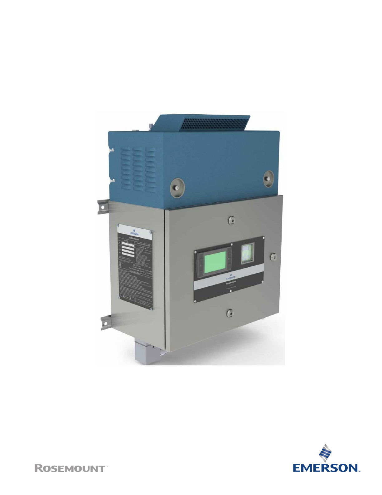
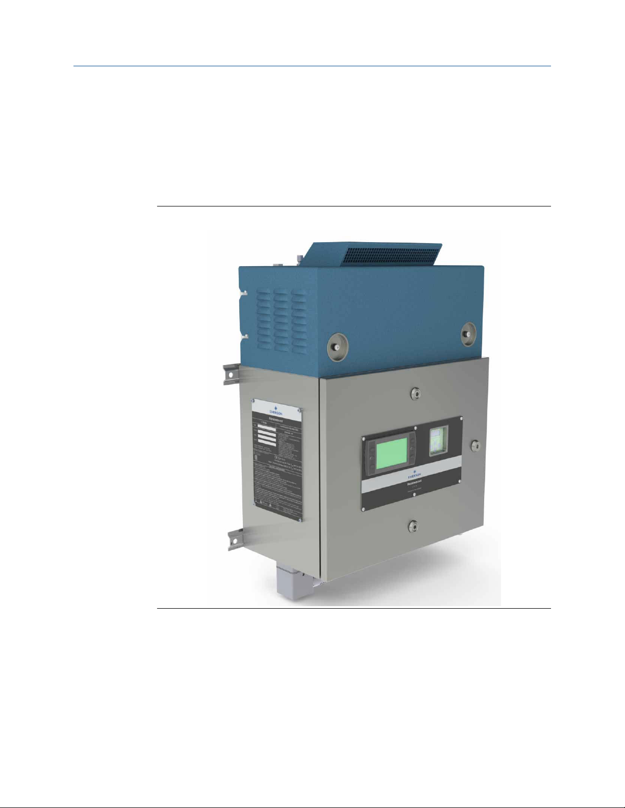
Figure 2-1: Rosemount CT5100(Ex) Continuous Gas Analyzer
The analyzer can be configured to detect and measure up to different gases, depending on
the combination of laser modules fitted.
Quick Start Guide 21
Page 22
Description
February 2020 00825-0100-4512
Quick Start Guide
2.2 System overview
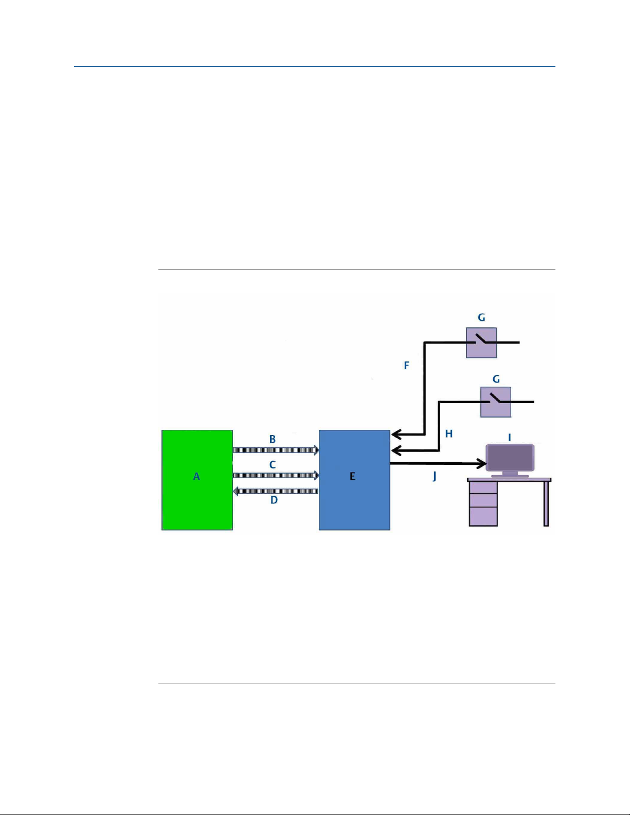
A complete Rosemount CT5100(Ex) system consists of the analyzer, and the associated
interconnecting wiring and gas piping.
The Rosemount CT5100(Ex) is supplied by Emerson. The gas handling system may be
provided by either you or Emerson, depending upon the specific installation. The circuit
breakers used to control the application of electrical power to the analyzer, the
interconnecting wires, and gas piping are provided by you.
In Figure 2-2, the items supplied by Emerson are colored blue; the items supplied by you
are colored purple. The green gas handling system may be provided by Emerson or you.
Figure 2-2: Complete Rosemount CT5100(Ex) Installation
A. Gas handling system
B. Instrument air
C. Sample supply line
D. Sample return (exhaust) line
E. Rosemount CT5100(Ex)
F. Electrical power
G. Two pole main isolator
H. Purge power
I. Control center
J. Measurement data
There is no sample conditioning provided within the analyzer; the sampled gas
requirements for the analyzer to operate are defined in the Environmental Characteristics
22 Rosemount CT5100(Ex)
Page 23
Quick Start Guide
00825-0100-4512 February 2020
(Table 3-3). Detailed characteristics of the analyzer are given in Rosemount CT5100(Ex)
Reference Manual.
Description
2.3 Gas flow through analyzer
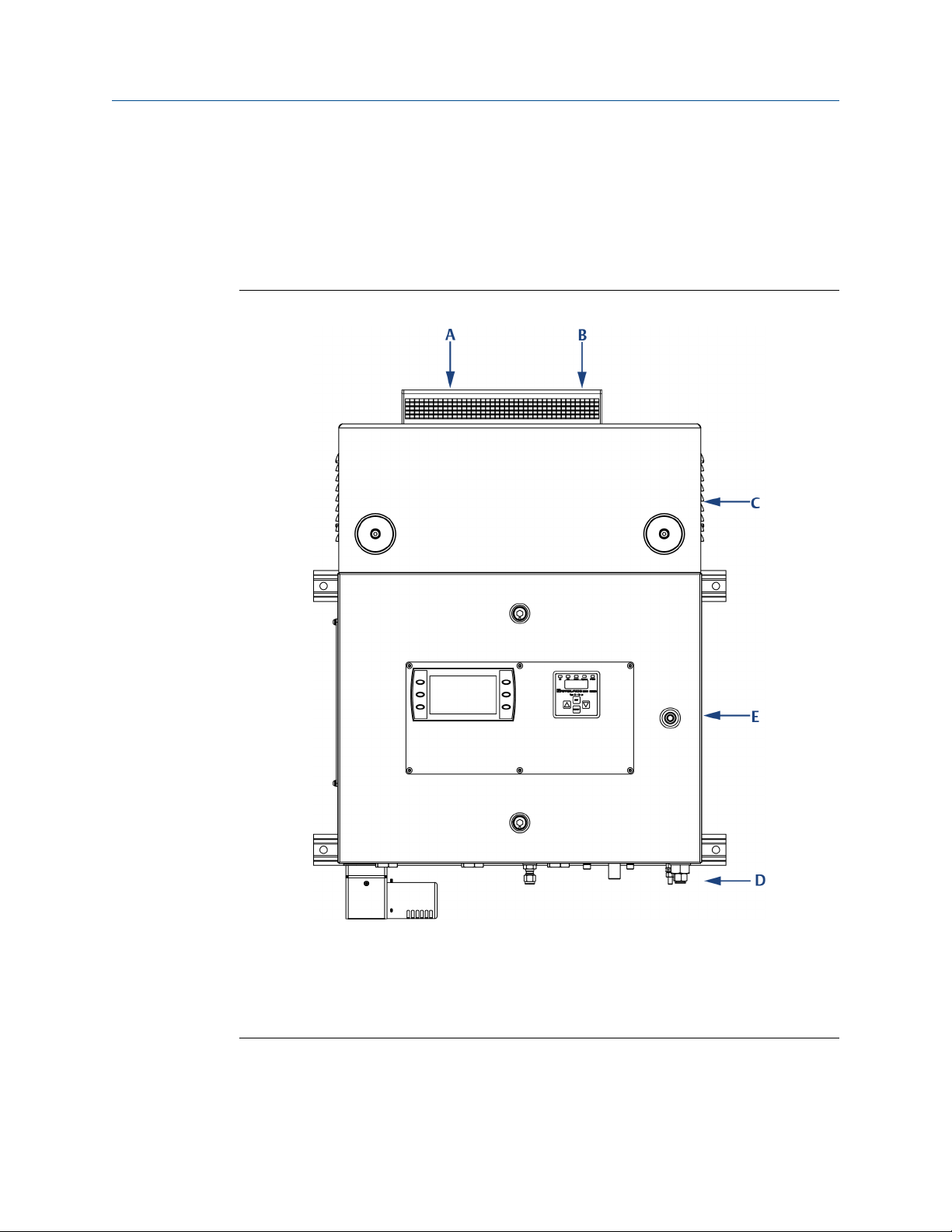
The analyzer has two gas inputs and one gas output. See Figure 2-3.
Figure 2-3: Gas Inlet and Outlet Connectors
A. Sample gas return port
B. Sample gas input port
C. Top cover of Rosemount CT5100(Ex) (cell compartment)
D. Purge air supply
E. Laser/electrical compartment
Quick Start Guide 23
Page 24

Description Quick Start Guide
February 2020 00825-0100-4512
Procedure
1. The gas sample that is to be measured for impurities enters the analyzer through
the sample gas input port located on top of the analyzer (see Figure 2-3, Items A
and B).
2. Once the gas sample has been examined for impurities, it is expelled from the
analyzer through the sample gas return port (A).
3. A compressed air supply enters the analyzer through a port (D) on the underside of
the unit.
The sample supply line must be heated all the way to the sample gas input port on
the analyzer to prevent condensation forming at any point in the sample supply
line.
WARNING
AIR SUPPLY
The air supply must be clean, filtered, and free from moisture.
24 Rosemount CT5100(Ex)
Page 25
Quick Start Guide
00825-0100-4512 February 2020
Description
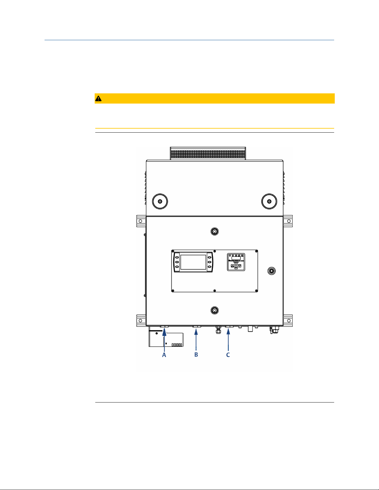
2.4 Connecting the electrical/electronic inputs and outputs
CAUTION
If the equipment is used in a manner not specified by the manufacturer, the protection
provided by the equipment may be impaired.
Figure 2-4: Electrical/Electronic Connectors
A. Purge power and alarm entry point
B. Power entry point
C. Analog/digital entry point
Electrical/electronic signal connections to the analyzer are made through three electrical
entry points located on the underside of the analyzer, as shown in Figure 2-4. Use the
wiring diagram to make the electrical connections as shown in Engineering drawings and
Figure 2-5.
Quick Start Guide 25
Page 26

Description
Quick Start Guide
February 2020 00825-0100-4512
Figure 2-5: Signal Cable Outputs
A. To mains input fuses
B. Mains input filter
C. To enclosure earth stud
D. To digital modules
E. To analog modules
F. To status relays
G. Digital output terminals
H. Analog output terminals
I. Status output terminals
J. Mains input terminals
Note
Purge solenoid fitted can be either for 5500-MAN-EX01 for ATEX/IEC applications or 5500MAN-CD01 for North American applications.
Note
Maximum number of user terminals shown. These may be reduced depending on number
and type of analog/digital outputs required.
Two sources of electrical power are applied to the analyzer through power entry points
(see Figure 2-4 Items A and B).
1. A purge electrical supply that is used to power the overpressure facility in the
electrical compartment of the analyzer entry point (A).
2. An instrumentation electrical supply that is used to power all other functions of the
analyzer entry point (C).
26 Rosemount CT5100(Ex)
Page 27

Quick Start Guide Description
00825-0100-4512 February 2020
Both power supplies are 110 to 230 Vac, 50/60 Hz ± 10%. AC to DC power converters
inside the analyzer automatically adjust in response to the input voltage level and ensure
that the correct DC voltage is available inside the unit. The analyzer is electrically
protected by an internal 5 A, 250 VA fast acting fuse on the instrumentation electrical
supply line and an internal 2 A, 250 VA fuse on the purge electrical supply line.
The wiring diagram (Figure 2-6) for the purge electrical supply is in accordance the with
the latest Pepperl+Fuchs 5500 Series Installation Manual Purge and Pressurization System
documentation (www.Pepperl-fuchs.com). It is recommended that these instructions are
verified from the Pepperl+Fuchs website to ensure the latest wiring instructions for the
purge controller have been followed during installation. The complete wiring diagram
used during the manufacture of the Rosemount CT5100(Ex) is included for reference in
Engineering drawings.
Figure 2-6: Pepperl +Fuchs Wiring Diagram (External Mount)
Figure 2-7: Pepperl +Fuchs Wiring Diagram (Internal Mount)
Figure 2-8: Pepperl +Fuchs Wiring Diagram (Terminal Block Connections)
Quick Start Guide 27
Page 28

Description Quick Start Guide
February 2020 00825-0100-4512
General wiring instructions for the Pepperl+Fuchs 5500 series purge control power
connection are as follows:
• All applicable local and national wiring codes MUST be followed when wiring the
system. Also see IEC60079-14.
• The power supply to this device shall have a separate customer installed external
disconnect. If placed in the hazardous area, it shall be rated for the area it is being
installed in. Placing the disconnect into the purged enclosure is not an option as power
needs to be applied to the control unit before the purge cycle is complete.
• PE ground wire to be same size as largest wire used to bring power into the enclosure.
Terminate using ring lug properly crimped at grounding stud in bottom of enclosure.
• All wire shall be copper only, rated 176 °F (80 °C) minimum.
• The minimum wire strand in a stranded wire shall have a diameter of 0.004-in.
(0.1 mm) or greater.
• Wire strip length into fixed terminal block is 0.315 in. (8 mm).
• Terminal torque is 0.5 Nm to 0.6 Nm.
• There shall be only one wire per terminal.
• It is recommended to leave a bit of extra wire loop in housing to allow for any re-
termination.
28 Rosemount CT5100(Ex)
Page 29

Quick Start Guide Specifications
00825-0100-4512 February 2020
3 Specifications
3.1 Detailed system specifications
Table 3-1 gives the physical characteristics for the analyzer while Table 3-2 gives the
general characteristics. Schematic diagrams of the analyzer are shown in Figure 3-1, Figure
3-2, and Figure 3-3.
Table 3-1: Physical Characteristics
Rosemount CT5100(Ex) Value Comment
External dimensions 22.68 x 11.7 x 30.94 in.
575 x 298 x 786 mm
Weight 121 lb
55 kg
Length x width x height
Nominal dimensions
Approximate weight
Table 3-2: General Characteristics
Rosemount CT5100(Ex) Value Units Comment
Instrumentation supply voltage 110 or 230 Vac 50/60 HZ ±10%
Purge supply voltage 110 or 230 Vac 50/60 Hz ±10%
Peak power consumption 500 W Max consumption per gas analyzer
Continuous steady-state power
consumption
Electrical compartment enclosure N/A N/A Stainless steel
Optical compartment enclosure N/A N/A Stainless steel
Measurement technique N/A N/A Mid IR absorption spectroscopy
Operating conditions
Mid IR source N/A N/A Quantum Cascade Laser
Near IR source N/A N/A Interband Cascade Laser
300 W Once the gas analyzer has stabilized and
the analysis cell has reached the
temperature set point
Diode Laser
Laser classification Class 1 N/A BS EN 60825-1: 2007 safety of laser
products. Equipment classification and
requirements (identical to IEC 60825-1
2007)
Inlet gas port connector ¼
6
Outlet (exhaust) gas port connector ¼
6
Purge connector ⅜
10
Purge air pressure 2 Barg N/A
Quick Start Guide 29
in.
mm
in.
mm
in.
mm
Swagelok® type, factory-configured,
specify on order
Swagelok type, factory-configured, specify
on order
Purge inlet (certified system only)
Page 30

Specifications Quick Start Guide
February 2020 00825-0100-4512
Table 3-2: General Characteristics (continued)
Rosemount CT5100(Ex) Value Units Comment
Measurement result signals 4 to 20 mA 4 or 8 channel outputs, specify on order
Communication 10/100 Mbps Ethernet
Warm-up time 90 minutes N/A
Figure 3-1: Rosemount CT5100(Ex) Dimensions - Front View
A. Ventilation
B. Lifting eyelet
C. User interface
D. Purge control panel
Dimensions are in inches (mm)
30 Rosemount CT5100(Ex)
Page 31

Quick Start Guide Specifications
00825-0100-4512 February 2020
Figure 3-2: Rosemount CT5100(Ex) Dimensions - Top View
A. Ventilation
B. Lifting eyelet
C. Sample return
D. Sample inlet
Dimensions are in inches (mm)
Figure 3-3: Rosemount CT5100(Ex) Dimensions - Bottom View
A. Atmospheric pressure refer plug
B. Earth point
C. Purge pressure set
D. Air supply
E. Cable glands
F. Purge vent
Dimensions are in inches (mm)
Quick Start Guide 31
Page 32

Specifications Quick Start Guide
February 2020 00825-0100-4512
Table 3-3: Environmental Characteristics
Environmental characteristic Value Units Comment
Operating temperature range -4 to 131
-20 to 55
Sample gas temperature range
(Condition for safe use Europe)
Sample gas temperature range
(Condition for safe use North
America)
Sample gas particulate density 5 mg/m
Sample gas particulate size 10 µm Maximum
IP code 66 N/A IP to IEC 60529
Sensor humidity range 10 to 95 % Relative humidity (non-
122 to 329
50 to 160
122 to 176
50 to 80
°F
°C
°F
°C
°F
°C
Ambient temperature
Factory set, specify on order
Factory set, specify on order
3
Maximum
condensing) at 113 °F (45 °C)
3.2 Safety and system labels and annotation
The labels and annotation applied to the analyzer are specified in the table below.
Label type
Identification label (including serial
number and model number
Example Location
Front panel
Fuse identification label 1. Back plate
2. Top right inside of door
IECEx and ATEX ratings label Enclosure side panel
32 Rosemount CT5100(Ex)
Page 33

Quick Start Guide Specifications
00825-0100-4512 February 2020
Label type Example Location
North America/Canada ratings label Enclosure side panel
Universal ratings label Enclosure side panel
Laser radiation CAUTION label Baseplate
Laser module identification label On each laser module housing
Intrinsically safe label 1. HMI
2. Intrinsically safe sensor barrier
Quick Start Guide 33
Page 34

Specifications Quick Start Guide
February 2020 00825-0100-4512
Label type Example Location
Terminal label (typical layout) Top left inside of door
Earth identification label Back plate
Manufacturer's label On analysis cell heater block
Electrical safety label On inside of electrical compartment
door
AC power supply danger label 1. On outside of electrical
compartment door
2. On manifold block of air
overpressure system
34 Rosemount CT5100(Ex)
Page 35

Quick Start Guide Install
00825-0100-4512 February 2020
4 Install
4.1 Site selection
The Rosemount CT5100(Ex) has a T3 temperature classification. The user must ensure
that no combustible gas concentrations will be present, whether on a continual or
occasional basis, which have an ignition temperature below the T3 rating of the analyzer.
DANGER
FIRE AND EXPLOSION
The analyzer's electrical compartment must not be opened unless the atmosphere in the
area is known to be below the ignitable concentration of combustible gases or materials,
or unless all equipment within the protected enclosure is de-energized in accordance with
NFPA496.
Death, personal injury, and/or damage to persons and/or property may result if this is not
observed.
DANGER
ELECTRIC SHOCK
The analyzer operates using mains voltage, which may cause death or serious injury to
personnel. Ensure that the circuit breakers are set to Off and locked out and tagged out off
before removing the top cover or opening the front cover.
Failure to observe this precaution will cause death, personal injury, and/or damage to
persons and/or property.
The analyzer is intended to be installed in a suitable Division 2 shelter to protect it from the
elements.
Provide sufficient space around the analyzer to allow the maintenance and servicing of the
unit.
Quick Start Guide 35
Page 36

Install Quick Start Guide
February 2020 00825-0100-4512
Figure 4-1: Clearance with Door Open
A. Door open
B. Door closed
C. Door opening arc
Dimensions are in inches (mm)
4.2 Unpacking
This procedure requires a minimum of two people to safely remove the equipment from
the shipping container.
WARNING
HEAVY INSTRUMENT - LIFTING HAZARD
Handle the analyzer with caution during unpacking, installation, maintenance, and
transport to prevent crushing of hands, feet, or other body parts.
The analyzer weighs 121 lb (55 kg) and should always be lifted and moved using suitable
lifting/moving equipment. Emerson recommends that a minimum of two people using
suitable tools for transportation and lifting are employed.
Wear suitable protective gloves and protective footwear.
36 Rosemount CT5100(Ex)
Page 37

Quick Start Guide
00825-0100-4512 February 2020
Install
CAUTION
EQUIPMENT DAMAGE
When preparing the analyzer for transport by air, road, or rail, safeguard the analyzer
against movement or break-away during transport by securely strapping it in place.
Failure to observe may cause damage to the equipment.
WARNING
EXPLOSION HAZARD
In accordance with IEC 60079-0: 2011 Clause 30.
Installing and wiring the analyzer must comply with all relevant national legislative
requirements and regulations.
Consider all safety instructions within this manual and all associated analyzer instruction
manuals.
WARNING
EXPLOSION HAZARD
In accordance with IEC 60079-0: 2011 Clause 30.
Installing the analyzer requires opening the enclosure and working at the open unit. This is
permitted only when both the analyzer and connected external circuitry are de-energized.
Depending on the local regulation, this may require a competent hot work supervisor to
issue a hot work permit.
CAUTION
SHOCK AND VIBRATION
The analyzer contains sensitive electronic equipment. It MUST NOT be subjected to any
shock and or vibration.
Damage to the analyzer may result from a failure to follow this caution.
Procedure
1. On receipt of goods, look for any visible damage to the analyzer and verify that all
items noted to be shipped were received. Record on the goods receipt note any
damage or missing items, noting both the item(s) and quantity missing.
2. Visually inspect the exterior of the analyzer for signs of damage, corrosion, gas
leaks, or signs of previously overheating.
3. Report anything found to the maintenance organization.
4. Attach suitably rated and tested lifting slings to the safety engineered lifting eye
bolts mounted on top of the analyzer.
5. One person should carefully guide the equipment from the horizontal to vertical
position while the other person lifts the equipment.
Quick Start Guide 37
Page 38

Install Quick Start Guide
February 2020 00825-0100-4512
6. Use safety approved and tested lifting equipment to remove the analyzer from the
shipping container and place it on a solid, level surface.
7. Ensure that the analyzer is stored in its protective plastic cover until installation.
4.3 Mounting the analyzer
This procedure requires two people to safely move and mount the Rosemount
CT5100(Ex).
Procedure
1. Ensure that there is free space around the analyzer to allow ventilation of the upper
part of the analyzer.
WARNING
HEAVY ITEM
In accordance with IEC 60079-0: 2011 Clause 30.
Failure to propery handle the analyzer may cause injury to personnel.
Ensure the wall the analyzer is mounted on is solid, stable, and of suitable material
to hold the weight of the analyzer.
Handle the analyzer with caution during unpacking, installing, maintaining, and
transporting to prevent crushing of hands, feet, or other body parts.
The analyzer weighs 121 lb (55 kg).
Emerson recommends that a minimum of two people move and lift the analyzer.
Wear suitable protective gloves and protective footwear.
2. Attach suitably rated and tested lifting slings to the safety engineered lifting eye
bolts (see Figure 4-2, items A and D) mounted on top of the analyzer.
38 Rosemount CT5100(Ex)
Page 39

Quick Start Guide
Install
00825-0100-4512 February 2020
Figure 4-2: Front View Dimensions
A. Lifting eye bolt
B. Sample gas input port
C. Sample gas return port
D. Lifting eye bolt
E. 0.413-in. (10.5 mm) diameter mounting points
F. Purge compressed air supply port
Dimensions are in inches (mm)
3. One person should carefully guide the equipment while the other person operates
the lifting equipment.
4. Use safety approved and tested lifting equipment to lift the analyzer from the stable
platform.
Quick Start Guide 39
Page 40

Install Quick Start Guide
February 2020 00825-0100-4512
5. Mount the analyzer using four M8 (⅜-in.) fasteners to attach the wall mount
brackets.
The bolts must be positioned in such a way to allow maximum use of all thread
length.
The installer must ensure that the fasteners used are suitable for the load and
surface that the analyzer is mounted on.
In case you need to thread lock the fittings for extra security, only do this with
compounds compatible with the zone classification of the installation location.
The four wall fixing points must be 0.413-in. (10.5 mm) diameter mounting holes.
Ensure that the wall fixing points are capable of supporting a load of 242 lb (110 kg)
each; this includes a x 2 factor of safety. Figure 4-4 shows the locations of the
mounting points on the analyzer. All mounting points are 0.413-in. (10.5 mm)
diameter holes.
Confirm the bolts are secure. Do not overtighten the fasteners.
The analyzer must be mounted using the four off factory fitted and predrilled holes
on the brace bars. Refer to Figure 4-2.
6. Remove the lifting eyes and retain them for future use.
Threads must be protected with a suitable grease and plastic grommets.
After mounting, do not place any additional load on the analyzer.
Do not place or leave loose items on flat surfaces.
For transportation, the purge vent (D) located on the base of the analyzer is fitted
with a temporary protector cap (C). This protector cap MUST remain in place until
the analyzer is commissioned. Refer to Figure 4-3.
The vent cap (A), O-ring (E) and grub screws (B) are shipped loose in the crate. Refer
to Figure 4-3.
40 Rosemount CT5100(Ex)
Page 41

Quick Start Guide Install
00825-0100-4512 February 2020
Figure 4-3: Connecting the Purge Vent Cap
A. Vent cap
B. 3/32-in. socket grub screws
C. Protector cap
D. Purge vent
E. O-ring
7. To complete the installation, remove the protector cap from the purge vent and the
O-ring (E). Install the vent cap, locking it in position with the grub screws.
Refer to Figure 4-2. An Allen key is provided for the grub screws.
The protector cap (C) must be retained as it will need to be refitted whenever the
analyzer is being shutdown for a prolonged period to seal the purge vent from fluid
ingress.
Quick Start Guide 41
Page 42

Install Quick Start Guide
February 2020 00825-0100-4512
Figure 4-4: Mounting Details
A. Mounting points
Dimensions are in inches (mm)
42 Rosemount CT5100(Ex)
Page 43

Quick Start Guide Install
00825-0100-4512 February 2020
Figure 4-5: Clearance with Door Open
A. Door open
B. Door closed
C. Door opening arc
Dimensions are in inches (mm)
4.4 Connecting the electrical/electronic inputs and outputs
4.4.1 AC power
Power is connected to the analyzer instrumentation through the power entry point (B) and
the purge controller through the purge power and alarm entry point (A) fitted to the base
of the analyzer. Refer to Figure 4-6.
Quick Start Guide 43
Page 44

Install Quick Start Guide
February 2020 00825-0100-4512
Figure 4-6: Power Gland
A. Purge power and alarm entry point
B. Power entry point
• A purge electrical and alarm supply that is used to power the overpressure facility in the
electrical compartment of the analyzer. Refer to Figure 4-6 (Item A).
• An instrumentation electrical supply that is used to power all other functions of the
analyzer. See Figure 4-6 (Item B).
The customer supplied circuit breakers must be in accordance with ATEX / IECEx / North
American protection concepts. The main power isolator controls the application of
electrical power to the purge controller with the secondary power isolator controlling the
application of electrical power to the remaining analyzer functions.
44 Rosemount CT5100(Ex)
Page 45

Quick Start Guide Install
00825-0100-4512 February 2020
Figure 4-7: Power Entry Point Connections
A. To mains input fuses
B. Mains input filter
C. To enclosure earth stud
Table 4-1: Mains Input Terminal
Terminal Function
1 Sensor system supply (L)
2 Sensor system supply (N)
3 Earth
Quick Start Guide 45
Page 46

Install
Quick Start Guide
February 2020 00825-0100-4512
Figure 4-8: Purge Power and Alarm Entry Point Connections
A. SV1
B. Power
C. Bypass
D. To purge solenoid
E. To be run separately from other cables looms
F. To PT100 sensor
Note
Purge control system power and alarm contact to be directly wired into purge control unit
by end user. The cables must use cable glands suitable for the zone of application of the
analyzer for entry into the analyzer enclosure and the purge control unit.
Terminal
L Purge control supply (live)
N Purge control supply (neutral)
K1 (normally open) Alarm contract
K2 (normally closed) Alarm contract
Function
Electrical protection for the instrumentation circuitry of the analyzer is provided by fuses
F1 and F2 located inside the analyzer. Refer to Figure 4-9.
The customer supplied power cable for the analyzer instrumentation will be connected to
terminals 1 - 3.
46 Rosemount CT5100(Ex)
Page 47

Quick Start Guide Install
00825-0100-4512 February 2020
Table 4-2: Electrical Power Requirements
4.4.2
Electrical supply Power
consumption
Instrumentation supply
voltage
Purge supply voltage 100 to 230 Vac, 2.3
400 W 100 to 230 Vac, 50/60 Hz ±10% 3.15 A
VA (without digital
valve)
Voltage Fuse
internal
fuses
F1 and F2
100 to 240 Vac, 48/62 Hz ± 10%,
single phase Overvoltage
category 2
AC: 2.0A
For the electrical power wiring use 16 AWG stranded, three conductor copper or tin-plated
copper power wire, rated for at least 250 Vac, of the required length. Cables must be
terminated in the power entry points in accordance with local electrical codes. The full
electrical wiring diagram is provided in Engineering drawings.
Fuses
Figure 4-9 shows the location of the fuses.
Figure 4-9: Fuses
A. Fuse F4 (24 Vdc supply)
B. Fuse F3 (12 Vdc supply)
C. Fuse F1 (mains supply – live)
D. Fuse F2 (mains supply – neutral)
Quick Start Guide 47
Page 48

Install Quick Start Guide
February 2020 00825-0100-4512
Table 4-3: Fuse Requirements
Fuse Function Rating Schurter part number
1 Live line 110/230 Vac
(following mains filter)
2 Neutral line 110/230
Vac (following mains
filter)
3 Analyzer 12 Vdc supply
rail
4 Analyzer 24 Vdc supply
rail
3.15 A, 250 V, fast
acting ceramic
3.15 A, 250 V, fast
acting ceramic
5 A, 250 V, fast acting
ceramic
3.15 A, 250 V, fast
acting ceramic
0001.1009
0001.1009
0001.1011
0001.9011
4.4.3 Connecting the sample supply and return line
Sample gas supply and sample return connections are ¼-in. (6 mm) ”Hamlet”
compression tube fittings. To avoid the risk of gas leaks, confirm that these connections
are made correctly and tightly. Both the sample gas supply pipe and the sample return
pipe should be thermal insulated.
The maximum sample gas supply pressure is 2 BarG.
4.4.4
Connecting the signal cables
The signal cables are connected to the system through an entry point outlet C, as shown in
Figure 4-10. All signal cables are to be minimum 20 AWG tri-rated switchgear cable.
Customer supplied conduit and cables are to be terminated in the entry point provided in
accordance with local electrical codes.
48 Rosemount CT5100(Ex)
Page 49

Quick Start Guide Install
00825-0100-4512 February 2020
Figure 4-10: Signal Cable Outputs
A. To digital modules
B. Digital output terminals
C. To analog modules
D. Analog output terminals
E. To status relays
F. Status output terminals
Table 4-4: User Connections
Terminal Function
11 Digital output 1
12 Digital output 2
13 Digital output 3
14 Digital output 4
15 Digital output 5
16 Digital output 6
17 Digital output 7
18 Digital output 8
19 Digital output 9
20 Digital output 10
21 Digital output 11
22 Digital output 12
Quick Start Guide 49
Page 50

Install
February 2020 00825-0100-4512
Table 4-4: User Connections (continued)
Terminal Function
23 Analog output 1
24 Analog output 2
25 Analog output 3
26 Analog output 4
27 Analog output 5
28 Analog output 6
29 Analog output 7
30 Analog output 8
31 Status output 1 (check function)
32 Status output 2 (maintenance required)
33 Status output 3 (out of specification)
34 Status output 4 (failed)
Quick Start Guide
4.4.5 Power input cables and circuit breakers
WARNING
FLAMMABLE/EXPLOSIVE GASES
The purge/pressurization cycle expels any flammable or explosive gases from the electrical
compartment and MUST be completed before applying electrical power to the rest of the
analyzer.
Failure to observe this warning could cause an explosion or potentially hazardous
situation, which if not avoided, may cause death, personal injury, and/or damage to
persons and/or property.
The power input cable/purge power cable circuit breakers can be tested as follows:
• Set the Purge circuit breaker to ON. The purge / pressurization process will start ONLY
when the K1 LED on the purge control panel comes on indicating the purge process is
complete can you proceed to the next step. Refer to Figure 5-4.
• The main power input circuit breaker can now be set to ON.
• Check that the display controller lights up. The analyzer will then begin to power-up.
4.4.6
Temperature sensor and cell heater
The sample cell is controlled to operate at a pre-set temperature. This involves a heater
and a temperature sensor. To test these, check that a temperature reading is displayed
against temperature on the display controller as described in Pressure and temperature
screen.
50 Rosemount CT5100(Ex)
Page 51

Quick Start Guide Install
00825-0100-4512 February 2020
Leave the analyzer operating and confirm that the temperature rises until the analysis cell
reaches the pre-set operating temperature around 122 °F (50 °C). This will take
approximately 90 minutes.
4.4.7 Pressure sensor
The pressure sensor monitors the pressure in the analysis cell. To test that it is functioning,
check that a pressure reading is displayed under pressure on the Beka Display Controller as
described in Pressure and temperature screen.
The reading will be approximately 760 Torr at atmospheric pressure. If desired, cap off the
gas inlet and use an external pump to evacuate the cell. Verify that the pressure drops as
expected.
NOTICE
A Torr is a non-SI unit of pressure, defined as 1/760 of standard atmospheric pressure, and
is equal to the fluid pressure of 1 mm of mercury.
4.4.8
4.4.9
Analog output cables
In order to generate a 4-20 mA output, the analyzer must be left for 90 minutes to warm
up, and the analysis cell must be at the correct pressure.
The 4-20 mA outputs will operate when the analysis cell temperature and pressure are
within the required test range. It is not essential to flow sample gas through the system;
nitrogen or atmospheric air will be adequate for this test.
With the analyzer at operating temperature and pressure, ensure that a current between
4 mA and 20 mA is generated on each 4-20 mA output. This can either be measured as a
current with a multimeter, or as a gas concentration through the control station.
Ethernet
To test the Ethernet connection, connect a remote laptop to the Ethernet port and
attempt to connect to the internal PC as described in the separate connection procedure.
It is not necessary to run the gas sensor on the laptop; once connected, enter the
command exit to disconnect again.
DANGER
FIRE AND EXPLOSION
The electrical compartment of the analyzer must not be opened unless the atmosphere in
the area is known to be below the ignitable concentration of combustible gases or
materials, or unless all equipment within the protected enclosure is de-energized in
accordance with NFPA 496.
Death, personal injury and/or damage to persons and/or property may result if this is not
observed.
Quick Start Guide 51
Page 52

Install Quick Start Guide
February 2020 00825-0100-4512
4.4.10 Seal glands
Where poured seal glands are a local industry requirement for cable termination, they
should be made in accordance with the manufacturer’s instructions once acceptance tests
have been made on the system to ensure that the analyzer does not need to be removed.
4.4.11 Commissioning
Once the sensor is fully installed as described above, it should be commissioned in
accordance with the commissioning plan agreed between Emerson and the customer.
52 Rosemount CT5100(Ex)
Page 53

Quick Start Guide Controls and display controller
00825-0100-4512 February 2020
5 Controls and display controller
5.1 Front panel controls and indicators
The Rosemount CT5100(Ex) is configured from the two control displays located on the
front panel. Refer to Figure 5-1.
Figure 5-1: Front Panel
A. Display controller
B. Purge control panel
C. Protector cap
D. Purge vent
Quick Start Guide 53
Page 54

Controls and display controller Quick Start Guide
February 2020 00825-0100-4512
Figure 5-2: Exploded View
A. Vent cap
B. 3/32-in. socket grub screws
C. Protector cap
D. Purge vent
E. O-ring
The protector cap (Figure 5-2, C) must be removed from the purge vent (D) and replaced
with the vented cap (A) supplied with the unit.
NOTICE
On/Off circuit breakers
There are no On/Off switches on the analyzer. The application of electrical power to the
analyzer is controlled through two external circuit breakers.
Both external circuit breakers are simple two-pole on/off circuit breakers. Both must be set
to On to permit the safe operation of the analyzer.
Operation of the analyzer is controlled primarily through the display controller.
Refer to Figure 5-3.
54 Rosemount CT5100(Ex)
Page 55

Quick Start Guide Controls and display controller
00825-0100-4512 February 2020
Figure 5-3: Display Controller
The purge control panel (Figure 5-4) is used to program the operation of the overpressure
air system that prevents flammable and explosive gases from entering the analyzer's
electrical compartment. Adjustment of the overpressure air system MUST ONLY be
performed by maintenance personnel.
Five LEDs, identified as K1, K2, PSV, Bypass, and PT100, are located on the upper part of
the purge control panel. These five LEDs indicate the status of the overpressure air system.
Figure 5-4: Purge Control Panel
Quick Start Guide 55
Page 56

Controls and display controller Quick Start Guide
February 2020 00825-0100-4512
5.2 Display controller
Operation of the Rosemount CT5100(Ex) is controlled through the six buttons on the
display controller: Figure 5-5.
Figure 5-5: Display Controller Buttons
A. LCD display
B. Configurable button
C. Scroll up button
D. Scroll down button
The LCD display (A) can be used to display:
• Gas concentration measurements obtained.
• Operating temperature and pressure.
• Help screens.
• Step-by-step calibration.
• Diagnostics.
The two scroll buttons (C and D) are used to scroll through the information on the LCD
display. The right-hand scroll button (C) is used to scroll up, and the left-hand scroll button
(D) is used to scroll down
5.3 Gas sensor main screen
When the analyzer is switched on at the end of the start-up procedure, the Gas Sensor
Main screen (Figure 5-6) appears appears.
The Gas Sensor Main screen is the screen that is normally displayed.
NOTICE
The gas concentrations shown in the following screenshots may be different from those
shown in your particular analyzer. The screenshots indicate the functionality of the
software, which is the same regardless of the gases or gas concentrations being measured.
56 Rosemount CT5100(Ex)
Page 57

Quick Start Guide Controls and display controller
00825-0100-4512 February 2020
Figure 5-6: Gas Sensor Main Screen
The Gas Sensor Main screen displays the gas concentration measurements obtained by
the analyzer. In the example shown in Figure 5-6 the gases nitric oxide (NO), nitrogen
dioxide (NO2), oxygen (O2), carbon monoxide (CO), and carbon dioxide (CO2) are being
measured and, for each gas, the concentration detected is in parts per million (ppm) or
percentage as applicable.
The NOx reading is the total nitrogen oxide reading, a combination of nitric oxide (NO) and
nitrogen dioxide (NO2).
At the end of the start-up procedure, the gas measurements initially appear as 0.00 ppm
until the first readings are taken. After a few seconds, the initial gas concentrations are
displayed.
The Gas Sensor Main screen also shows the status of the analyzer. In the example shown
in Figure 5-6, the analyzer is Running and OK (e.g., no faults have been identified). This area
of the display shows any errors detected by the software.
On the software screens, highlighted items are links to other screens in the software. To
access a screen, press the button next to the highlighted item.
Quick Start Guide 57
Page 58

Controls and display controller Quick Start Guide
February 2020 00825-0100-4512
Figure 5-7: Gas Sensor Main Screen Buttons
A. MENU button
B. MENU text
C. PAGE text
D. PAGE button
E. HELP button
F. HELP text
G. STATUS button
PAGE text is a link between the Gas Sensor Main screen and the Pressure and
Temperature screen (described in Pressure and temperature screen). Press the PAGE
button to toggle between these two screens.
HELP text is a link to the Help system. Press to go to the Help screen (described in Help
system).
MENU text is a link to the Main Menu of the software. Press the MENU button to go to the
MAIN MENU screen (described in Main menu).
On the Gas Sensor Main screen, STATUS button (Figure 5-7) has no function when the
analyzer is operating correctly. If, however, the software detects a fault, an error message
is displayed. Press to get further information on the error.
5.4 Pressure and temperature screen
The Pressure and Temperature screen (Figure 5-8) shows pressure and temperature
measurements taken inside the analyzer.
58 Rosemount CT5100(Ex)
Page 59

Quick Start Guide Controls and display controller
00825-0100-4512 February 2020
Figure 5-8: Pressure and Temperature Screen
The Gas Te reading is the temperature, in °C, of the gas within the analysis cell.
The Pres reading is the pressure, in Torr, inside the analysis cell.
NOTICE
A Torr is a non-SI unit of pressure defined as 1/760 of standard atmospheric pressure and is
equal to the fluid pressure of 1 mm of mercury.
5.5 Help system
When the button is pressed it takes you to the home page. Figure 5-9 shows an
example of a help screen.
Figure 5-9: Example of a Help Screen
Quick Start Guide 59
Page 60

Controls and display controller Quick Start Guide
February 2020 00825-0100-4512
5.6 Main menu
To access the Main menu (Figure 5-10), press the MENU button on either side of the Gas
Sensor Main screen (Figure 5-6) or the Pressure and Temperature screen (Figure 5-8).
The Main menu (Figure 5-10) is used for calibration, diagnostics, fault finding,
downloading data, and shutting down the analyzer.
Figure 5-10: Main Menu
5.7 BACK button
On most of the software screens, (Figure 5-11) is configured as a BACK button. Press BACK
(A) to return to the previous screen.
Figure 5-11: BACK Button
A. BACK button
60 Rosemount CT5100(Ex)
Page 61

Quick Start Guide Start-up procedure
00825-0100-4512 February 2020
6 Start-up procedure
6.1 Introduction
CAUTION
EQUIPMENT DAMAGE
Damage to the analyzer may result from a failure to follow this procedure.
Always follow the start-up procedure.
The analyzer normally operates continuously. It should only be necessary to start up the
analyzer under the following circumstances:
• When the analyzer is first switched on following installation.
• Following repair or maintenance.
• When the analyzer has been switched off as part of a plant shutdown or maintenance.
6.2 Preparation for use
The Rosemount CT5100(Ex) must be installed and fully commissioned prior to start-up.
CAUTION
EQUIPMENT DAMAGE
Do not power up or try to operate the analyzer unless it is physically secure and all
electrical and pneumatic connections to the analyzer are in place.
Before commencing the start-up process, ensure that electrical power, sample gas
handling facilities, and any calibration gases that are required are available to the analyzer.
Failure to perform pre-system start-up checks may cause damage to equipment.
Quick Start Guide 61
Page 62

Start-up procedure Quick Start Guide
February 2020 00825-0100-4512
WARNING
BURN HAZARD
Some parts of the analyzer may be heated up to 320 °F (160 °C). To prevent burns, do not
touch any of the hot parts. All components of the analyzer are hot unless it has been
switched off and allowed to cool down.
Before fitting, removing, or performing any maintenance on the analyzer, ensure that it
has been switched off and allowed to cool for at least two hours. Before performing any
maintenance on or, in the vicinity of the analysis cell, allow the analyzer to cool for at least
twelve hours, as the analysis cell is insulated against heat loss.
When handling the analyzer, always use suitable protective gloves.
Personal injury and/or damage to property may result if these safety precautions are not
observed. These precautions are especially important when working at heights. If you
receive a burn, seek medical treatment immediately.
6.3 Start-up
Note
The gases shown in the screenshots and the measurements thereof may be different from
those shown in your particular Rosemount CT5100(Ex). They indicate the functionality of
the software, which is the same regardless of the gases being measured.
Note
To stop the start-up procedure at any time, set the main circuit breaker to Off.
To start up the analyzer,
Procedure
1. Visually inspect the exterior of the analyzer for signs of damage, corrosion, gas
leaks, or overheating. Report anything found to the maintenance organization.
2. Verify that the analyzer has been correctly installed as described in Install.
3. Ensure that the top cover is fitted to the analyzer. If it is not, report it to the
maintenance organization and do not proceed further until the top cover has been
fitted.
4. Confirm that the door to the electrical compartment is closed and locked. If the
door cannot be closed and locked, report it to the maintenance organization and do
not proceed further until the door has been repaired.
5. Ensure that the gas handling system is turned off.
6. Verify that the external main and secondary circuit breakers are set to Off.
7. Visually examine the three gas ports.
If necessary, refer to Figure 6-1 to ensure that the sample supply line, the sample
return line, and the compressed air line are correctly attached.
62 Rosemount CT5100(Ex)
Page 63

Quick Start Guide Start-up procedure
00825-0100-4512 February 2020
Figure 6-1: Rosemount CT5100(Ex) Gas Inlet and Outlet and Electrical
Connections
A. Sample gas return port
B. Sample gas input port
C. Top cover of analyzer (cell compartment)
D. Purge air supply
E. Laser/electrical compartment
F. Analog/digital power entry point
G. Power entry point
H. Purge power and alarm entry point
8. Visually check that the electrical connections have been made to the three power
entry points, Figure 6-1, at the base of the analyzer.
9. Visually check that the vent cap is fitted to the purge vent (Figure 4-3).
UNDER NO CIRCUMSTANCES may the analyzer be started with the protector cap
fitted as this will prevent the analyzer from venting during the purge process.
Quick Start Guide 63
Page 64

Start-up procedure Quick Start Guide
February 2020 00825-0100-4512
WARNING
FLAMMABLE/EXPLOSIVE GASES
The purge/pressurization cycle expels any flammable or explosive gases from the
analyzer's electrical compartment. The analyzer must be purged for a minimum of 2
minutes 30 seconds at a minimum flow rate of 280 L/m at 1.5 ± 0.5 bar to prevent
hazards to personnel during the startup process.
Only after the purge/pressurization cycle has been completed can electrical power
be applied to the rest of the analyzer.
10. Turn on the compressed air supply to the analyzer.
11. Set the main circuit breaker to On. The air pressurization will begin its automatic
start-up and begin to purge the air inside the analyzer.
Figure 6-2: Purge Control Panel
A. K1 LED
B. P/SV LED
C. PT100 LED
12. Observe the PT100 LED on the purge control panel (Figure 6-2).
If the PT100 LED (C) illuminates red, the air pressurization system is unserviceable,
and the start-up procedure must be halted immediately. To halt the start-up
procedure, set the external main circuit breaker to Off. Lock off or tag off the main
circuit breaker, turn off the compressed air supply, and report the fault to the
maintenance organization.
64 Rosemount CT5100(Ex)
Page 65

Quick Start Guide Start-up procedure
00825-0100-4512 February 2020
13. Observe the P/SV LED (B) on the purge control panel.
When the pre-set internal overpressure has been reached, the P/SV LED (B)
illuminates orange. If the P/SV LED (B) does not illuminate blue, the pressurization
system is unserviceable, and the start-up procedure must be halted immediately.
To halt the start-up procedure, set the external main circuit breaker to Off, lock off
or tag off the main circuit breaker, turn off the compressed air supply, and report
the fault to the maintenance organization.
WARNING
FLAMMABLE/EXPLOSIVE GASES
The purge/pressurization cycle expels any flammable or explosive gases from the
analyzer's electrical compartment. The analyzer must be purged for a minimum of 2
minutes 30 seconds at a minimum flow rate of 280 L/m at 1.5 ± 0.5 bar to prevent
hazards to personnel during the startup process.
Only after the purge/pressurization cycle has been completed can electrical power
be applied to the rest of the analyzer.
14. Wait until the purge cycle is performed.
Do not switch on the secondary circuit breaker until the purge cycle is complete.
Observe the K1 LED (A) on the purge control panel, which will illuminate green
when the purge cycle is complete.
15. When the purge/pressurization cycle is complete, set the secondary circuit breaker
to On, which applies electrical power to the rest of the analyzer.
The analyzer begins its automatic start-up. The control PC that forms part of the
analyzer is configured to automatically load the necessary gas sensor software and
configuration files. The start-up sequence commences automatically under
software control.
After a few seconds, the Gas Sensor main screen (Figure 6-3) appears on the display
controller. If it does not, report the fault to the maintenance organization.
Figure 6-3: Gas Sensor Main Screen
16. Start up the system for returning sample gas.
Quick Start Guide 65
Page 66

Start-up procedure Quick Start Guide
February 2020 00825-0100-4512
17. Start up the gas handling system that conditions the sample gas before it is fed into
the analyzer.
At the end of the start-up procedure, the gas measurements initially appear as 0.00 ppm
until the first readings are taken. After a few seconds, the initial gas concentrations are
displayed.
The start-up procedure is now complete.
6.4 Front panel controls and indicators
The is configured from the control display located on the front panel (Figure 6-4).
Figure 6-4: Front Panel
A. Display controller
B. Purge control panel
NOTICE
On/Off circuit breakers
There are no On/Off switches on the analyzer. The application of electrical power to the
analyzer is controlled through a customer provided external circuit breaker.
The circuit breaker is a simple two-pole on/off circuit breaker that must be set to On to
permit the safe operation of the analyzer.
66 Rosemount CT5100(Ex)
Page 67

Quick Start Guide Start-up procedure
00825-0100-4512 February 2020
Operation of the analyzer is controlled primarily through the display controller Figure 6-5.
Figure 6-5: Display Controller
CAUTION
DO NOT, under any circumstances, press the top two buttons on the display controller
simultaneously. This will override the system code supplied with the analyzer and display
the default program screen for the controller.
This will lock the software controlling the analyzer requiring the analyzer to shut down
externally and restarted risking a possible corruption of the software and loss of the
analyzer operation during the shutdown and restart process.
It is essential that only trained, qualified personnel operate the controls on the analyzer.
Failure to follow these instructions may cause warranty invalidation, property damage
and/or personal injury or death.
Figure 6-6: Default Program Screen
The purge control panel (Figure 6-7) is used to program the operation of the overpressure
air system that prevents flammable and explosive gases from entering the electrical
compartment of the analyzer. Adjustment of the overpressure air system must only be
performed by maintenance personnel.
Quick Start Guide 67
Page 68

Start-up procedure Quick Start Guide
February 2020 00825-0100-4512
Five LEDs, identified as K1, K2, PSV, Bypass, and PT100 are located on the upper part of the
purge control panel. These five LEDs indicate the status of the overpressure air system.
Figure 6-7: Purge Control Panel
68 Rosemount CT5100(Ex)
Page 69

Quick Start Guide ATEX/IECEX assessment report summary
00825-0100-4512 February 2020
7 ATEX/IECEX assessment report
summary
7.1 Certification overview
This article is in accordance with IEC 60079-0: 2011 Clause 30. This article must not be
changed amended or removed.
This report covers the assessment of the Rosemount CT5100(Ex) Continuous Gas Analyzer
to the standards listed in Assessment standards, in order to support the issue of prime
ATEX and IECEx certification.
7.2 Applicant's name and address
Cascade™ Technologies Ltd.
Glendevon House
Castle Business Park
Stirling
FK9 4TZ
UK
7.3 Manufacturer's name and address
As applicant.
7.4 Trademark
7.5 Product name/model number
Rosemount CT5100(Ex) Continuous Gas Analyzer
7.6 Rating
110 V to 120 V, 60 Hz
220 V to 240 V, 50 Hz
1100 W
Quick Start Guide 69
Page 70

ATEX/IECEX assessment report summary Quick Start Guide
February 2020 00825-0100-4512
7.7 Assessment standards
Table 7-1: Europe
IECEx ATEX
IEC 60079-0:2011 Ed 6 EN 60079-0:2012/A11:2013
IEC 60079-2:2014 Ed 6 EN 60079-2:2014
IEC 60079-28:2015 Ed 2 EN 60079-28:2015
(The requirements of the equivalent ATEX and IECEx standards are similar; therefore, any
references in the following report can be regarded as referring to either format unless
stated otherwise.)
This report may be issued against standards that do not appear on the UKAS Scope of
Accreditation, but have been added through Sira's flexible scope of accreditation. Sira's
flexible scope is available on request.
7.8 Markings
Table 7-2: IECEx and ATEX Markings
Detail IECEx ATEX
Certificate number IECEx SIR 16.0050X Sira 16ATEX1158X
Certification code EX ia d [ia Ga] op is pzc IIC T3 Gc Tamb
-20 to +55 ℃
Other marking N/A
Table 7-3: North American Markings
Detail CSA North American Marking
Certificate number 70044220
Marking class CLASS– 2258-02
Certification code Class I, Division 2, Groups A, B, C, D; T3. Tamb-20 °C to
+55 °C
Marking class CLASS– 2258-82
EX ia d [ia Ga] op is pzc IIC T3 Gc Tamb
-20 to +55℃
II 3 (1) G
Certification code Class I, Division 2, Groups A, B, C, D; T3. Tamb-20 °C to
+55 °C
70 Rosemount CT5100(Ex)
Page 71

Quick Start Guide ATEX/IECEX assessment report summary
00825-0100-4512 February 2020
Table 7-4: Common Markings
Details
Model number Rosemount CT5100(Ex) Continuous Gas Analyzer
Manufacturer's name Cascade Technologies Ltd
Manufacturer's address Glendevon House
Castle Business Park
Stirling
FK9 4TZ
UK
Ambient range -4 to 131 °F
-20 to 55 °C
Serial number As applicable
Year of manufacture As applicable
Quick Start Guide 71
Page 72

ATEX/IECEX assessment report summary Quick Start Guide
February 2020 00825-0100-4512
Table 7-4: Common Markings (continued)
Details
Warnings
(English/French)
WARNING
Pressurized enclosure
AVERTISSEMENT
Envelope à suppression interne
WARNING
Do not open when an explosive atmosphere is present.
AVERTISSEMENT
Ne pas ouvrir si une atmosphère explosive est présente.
WARNING
Power shall not be restored after an enclosure has been
opened until enclosure has been purged for a minimum of
two minutes 30 seconds at a minimum flow rate of 280
L/m at 1.5 ± 0.5 bar to prevent hazards to personnel during
maintenance.
AVERTISSEMENT
À la suite d’une ouverture, la mise sous tension ne doit pas
etre effectué avant que l’enveloppe n'ait été balayée
pendant 2½ minutes sous un débit de 280 L/min.
WARNING
This enclosure contains inert gas and may be an
asphyxiation hazard.
AVERTISSEMENT
Cette enveloppe contient un gaz inerte et peut constituer
un danger d'asphyxie.
WARNING
Batteries are located inside this enclosure. Do not open
when an explosive atmosphere is present.
AVERTISSEMENT
Présence de batteries à l'intérieur de cette enveloppe. Ne
pas ouvrir si une atmosphère explosive est présente.
WARNING
This pressurized enclosure contains a battery which
remains connected after the external power has been
isolated. Consideration should be given to the removal of
the battery if the enclosure is to remain unprotected by Ex
for a significant time.
AVERTISSEMENT
Cette enveloppe à surpression interne contient une
batterie qui reste connecté après que l'alimentation
externe a été isolée. Il convient de retirer la batterie s’il faut
que l'enveloppe reste sans protection ex pendant une
durée prolongée.
Type of protective gas
Minimum overpressure 0.5 mbar
Maximum overpressure 10 mbar
72 Rosemount CT5100(Ex)
Instrument quality air or inert gas
Page 73

Quick Start Guide ATEX/IECEX assessment report summary
00825-0100-4512 February 2020
Table 7-4: Common Markings (continued)
Details
Minimum purge flow rate 280 L/min
Leakage rate 25 L/min
Minimum purge supply pressure 1 Bar
Maximum purge supply pressure 2 Bar
Minimum purge time 2 minutes 30 seconds
Minimum supply pressure 1 Bar
Maximum supply pressure 2 Bar
7.9 Conditions of certification/special conditions for safe use
Europe
• The purge controller keypad mounted on the front of the equipment shall not be
exposed to direct UV light sources or direct sunlight. Example methods of protection
include, but are not limited to, indoor applications away from UV sources and outdoor
locations under shading. As part of regular inspections, if damage to or deterioration of
the membrane keypad is detected, the unit is to be taken out of service for repair or
replacement.
• The purge controller bypass function shall only be enabled during setup or
maintenance and only when the area is known to be non-hazardous.
• The equipment shall be installed in an area of not more than pollution degree 2 as
defined in IEC 60664-1.
• The cable glands used in the equipment are only suitable for use in areas with a low risk
of mechanical damage and must be suitably protected.
• Rosemount CT5100(Ex) purge controller automatically monitors the internal pressure
of the enclosure and will output any fault conditions onto contact K2. It is the
responsibility of the end user to connect this contact to a suitable facility, such as an
alarm or an automatic shutdown system.
• For correct operation the on-site pressurizing air supply must be capable of providing
at least 25 L/min for leakage compensation.
• When using the Rosemount CT5100(Ex) variant fitted with the Elmess gas cell heater
certified as BVS 14ATEXE155U and IECEx BVS 14.0106U, the equipment top
compartment should be cooled with a source of compressed air at a minimum flow
rate of 280 L/min.
• The Elmess gas cell heater certified as BVS 14ATEXE155U and IECEx BVS 14.0106U may
only be used in combination with the ESI Technology gas cell pressure transducer
certified as TRAC12ATEX0060X and IECEx TRC 12.0025X.
Quick Start Guide 73
Page 74

ATEX/IECEX assessment report summary Quick Start Guide
February 2020 00825-0100-4512
North America
• The purge controller keypad mounted on the front of the equipment shall not be
exposed to direct UV light sources or direct sunlight. Example methods of protection
include, but are not limited to, indoor applications away from UV sources and outdoor
locations under shading. As part of regular inspections, if damage to or deterioration of
the membrane keypad is detected, the unit is to be taken out of service for repair or
replacement.
• The purge controller bypass function shall only be enabled during setup or
maintenance and only when the area is known to be non-hazardous.
• The cable glands used in the equipment are only suitable for use in areas with a low risk
of mechanical damage and must be suitably protected.
• The purge controller provided with this equipment provides alarm signals at various
contacts as described in the equipment instructions. The alarms relate to low-flow and
loss of purged air supply and must be connected to the end-users remote, monitored,
alarm system.
• For correct operation the on-site pressurizing air supply must be capable of providing
at least 25 L/min for leakage compensation.
• This assessment does not cover reliable function, performance, or other properties of
the equipment not related to safety.
• The equipment is to be installed using wire no larger than the protective earth wire.
• Equipment is only to be installed by manufacturer trained personnel.
• If at anytime there is a conflict between the system safety provisions and any relevant
local (national or regional) requirements, the local requirements always take
precedence.
• Equipment is not to be used with flammable liquids.
• The relief valve sealing cap must be fitted to maintain IP66 when the unit is in a non-
operational state.
• Equipment is subject to acceptance of the local inspection authorities having
jurisdiction.
• The equipment is intended for use only with air of instrument quality; all piping up to
and including the shut-off valve adjacent to the equipment must be protected against
mechanical damage.
• The protective gas supply to the equipment must be marked with the warning as
detailed in NFPA496 Clause 4.12.5.
• When installing conduit for power and data connections the end-user must select
suitably certified conduit.
74 Rosemount CT5100(Ex)
Page 75

Quick Start Guide ATEX/IECEX assessment report summary
00825-0100-4512 February 2020
7.10 Conditions of certification for the replacement of simple devices
Approval for the PT100 temperature sensor as a simple device.
• To permit connection of a suitable temperature sensor, the following intrinsically safe
(IS) parameters have been declared.
• For the connections emerging from the purged enclosure:
Parameter IS
Voltage U
Current I
Power P
Capacitance C
Inductance L
o
o
o
i
i
12.4 V
17.4 mA
54 mW
0
0
• The capacitance and either the inductance or L/R of the load connected to hazardous
area terminals of the apparatus must not exceed the following values for Group IIC:
Capacitance Inductance L/R ratio
1.24 µF 117 mH 597 µH/ohm
The above parameters apply when one of the two conditions below is given:
• The total Li of the external circuit (excluding the cable) is < 1 percent of the Lo value or
• The total Ci of the external circuit (excluding the cable) is < 1 percent of the Co value.
The above parameters are reduced to 50 % when both of the two conditions below are
given:
• The total Li of the external circuit (excluding the cable) is ≥ 1 percent of the Lo value or
• The total Ci of the external circuit (excluding the cable) is ≥ 1 percent of the Co value.
Note
The reduced capacitance of the external circuit (including cable) shall not be greater than
600 nF for Group IIC.
Quick Start Guide 75
Page 76

ATEX/IECEX assessment report summary Quick Start Guide
February 2020 00825-0100-4512
76 Rosemount CT5100(Ex)
Page 77

Quick Start Guide Engineering drawings
00825-0100-4512 February 2020
A Engineering drawings
Use the wiring diagrams for the Rosemount™ CT5100(Ex) analyzer to assist with
troubleshooting faults. These diagrams may be used to locate the position of a wiring
connector should it become disconnected.
Table A-1: List of Engineering Drawings
Drawing number Description
W-2000-0034 (Sheets 1-5) Rosemount CT5100(Ex) heated
Quick Start Guide 77
Page 78

Page 79

Page 80

Page 81

Page 82

Page 83

00825-0100-4512
Rev. AA
2020
CASCADE TECHNOLOGIES
Glendevon House
Castle Business Park
Stirling FK9 4TZ
Scotland
+44 1786 447 721
+44 1786 475 822
cascade.support@emerson.com
EUROPE REGIONAL OFFICE
Emerson Automation Solutions
Neuhofstrasse 19a PO Box 1046
CH-6340 Baar
Switzerland
+41 (0) 41 768 6111
+41 (0) 41 768 6300
cascade.support@emerson.com
Linkedin.com/company/Emerson-Automation-Solutions
twitter.com/rosemount_news
Facebook.com/Rosemount
youtube.com/RosemountMeasurement
AMERICAS
Emerson Automation Solutions
10241 West Little York, Suite 200
Houston, TX 77040 USA
Toll Free 866 422 3683
+1 713 396 8880 (North America)
+1 713 396 8759 (Latin America)
+1 713 466 8175
cascade.support@emerson.com
MIDDLE EAST AND AFRICA REGIONAL
OFFICE
Emerson Automation Solutions
Emerson FZE
Jebel Ali Free Zone
Dubai, United Arab Emirates, P.O. Box 17033
+971 4 811 8100
+971 4 886 5465
cascade.support@emerson.com
©
2020 Emerson. All rights reserved.
The Emerson logo is a trademark and service mark of Emerson Electric Co. Rosemount is a
mark of one of the Emerson family of companies. All other marks are the property of their
respective owners.
ASIA-PACIFIC REGIONAL OFFICE
Emerson Automation Solutions
1 Pandan Crescent
Singapore 128461
Republic of Singapore
+65 6 777 8211
+65 6 777 0947
cascade.support@emerson.com
 Loading...