

Page 1
Reference Manual
00809-0100-4245, Rev AB
Rosemount™ CT4215 Leak Detection System
July 2018
Page 2

Preface
Published by EmersonTM.
All possible care has been taken in the preparation of this publication, but EmersonTM and its agents and distributors accept no
liability for any inaccuracies that may be found. This manual reflects the state of the product at the issure date below, but further
enhancements while in service may mean that the manual does not reflect your particular system.
Emerson reserves the right to make changes without notice both to this publication and the products which it describes.
Document number: 00809-0100-4245
Rev AB, July 2018
©
Emerson 2018. All rights reserved.
No part of this publication may be reproduced, stored in a retrieval system, or transmitted in any form or by any means electronic,
mechanical, photocopying, recording, or otherwise without the express prior written permission of the copyright holder.
If you require additional technical assistance, request help from (cascade.support@emerson.com) or Emerson distribution partners.
General inquiries should be sent to cascade.support@emerson.com.
All trademarks used within this document are the property of their respective owners.
Page 3

Important information
Important
Users must read, understand, and comply with the following information before proceeding.
All users, installers, operators, and maintainers must be familiar with operating the detector. To install, start up, operate, maintain,
and service the detector in a safe manner, it is MANDATORY to read all additional instruction manuals shipped with the detector.
The following instruction manual(s) are available and / or referenced within this manual:
RosemountTM CT4215 Quick Start Guide: 00825-0100-4245
User information
Important
All users must read this page before proceeding!
EmersonTM designs, manufactures, and tests its products to meet many national and international standards. The Rosemount
TM
CT4215 is a sophisticated technical product, and to ensure it continues to operate as designed and within normal specifications, it
MUST be installed, used, and maintained correctly.The following instructions MUST be adhered to and integrated into your safety
program when installing, using, and maintaining RosemountTM products.
• Failure to follow the proper instructions may cause:
- Loss of life
- Personal injury
- Damage to property
- Damage to this instrument
- Warranty invalidation
• Read all instructions prior to installing, operating, and servicing the product.
• If you do not understand any of the instructions, contact your RosemountTM representative for clarification.
• Follow all warnings, cautions, and instructions marked on and supplied with the product.
• Inform and educate your personnel in the proper installation, operation, and maintenance of the product.
• Install your equipment as specified in the installation instructions of the appropriate manual and in accordance with
applicable local and national codes.
• Connect all products to the proper electrical and pressure sources.
• To ensure proper performance, use qualified personnel to install, operate, update, program, and maintain the product.
• When replacement parts are requried, ensure that qualified people use replacement parts specified by EmersonTM.
• Unauthorized parts and procedures can affect the product’s performance, place the safe operation of your process at risk,
and VOID YOUR WARRANTY. Look-alike substitutions may result in fire, electrical hazards, or improper operation.
• To prevent electrical shock and personal injury, all equipment doors must be closed and protective covers in place, except
when maintenance is being performed by qualified personnel.
• The information contained in this document is subject to change without notice.
Page 4

General safety notice/residual risk
Installation, operation, and maintenance of the detector must be in accordance with these instructions.
When operated as intended and all applicable safety instructions are observed, an element of risk will remain, including, but not
limited to, the following:
• Explosion protection measures may become ineffective on the occurrence of one failure (for Category 3 instruments).
• The emission of gases hazardous to health may be possible when all gas connections have been correctly made.
To avoid exposure to the dangers of residual risks, take particular care when installing, operating, maintaining, and servicing the
detector.
Authorized personnel
In-depth specialist knowledge is an absolute requirement for working with and on the detector. Personnel installing, operating,
servicing, and maintaining the detector must be instructed, trained, qualified, and authorized for hazardous areas with the
operating company and the manufacturer. It is the operating company's responsibility to:
• Train staff.
• Observe safety regulations.
• Follow the safety instructions and procedures in the product manual.
Operators must:
• Be trained.
• Read and understand all relevant sections of the product manual before commencing work.
• Know the safety mechanisms and regulations.
WARNING!
To avoid explosions, loss of life, personal injury, and damage to this equipment and on-site property, do not install, operate,
maintain, or service this instrument before reading and understanding this instruction manual and receiving appropriate training.
Page 5
Regulations and standards
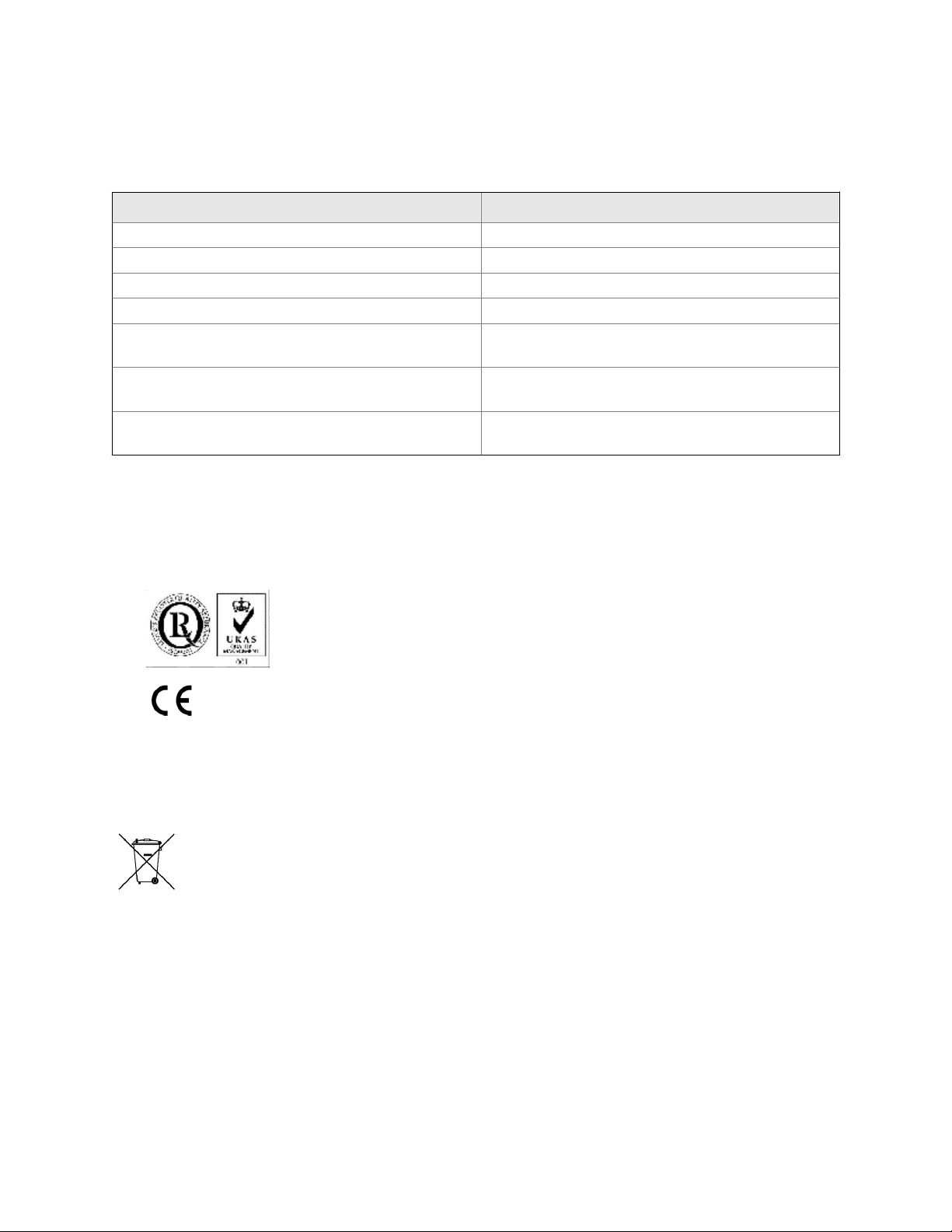
Regulations / Standards Description
2014/35/EU The Low Voltage Directive
2014/30/EU The Electromagnetic Compatibility Directive
2012/19/EU Waste Electrical and Electronic Equipment (WEEE) Directive
USA 21 CFR 1040.1 Laser products
BS EN 60825-1 Safety of laser products. Equipment classification and require-
ments (identical to IEC 608250-1 2007)
BS EN 61010-1 2010 IEC 61010-1 2010 Safety requirements for electrical equipment for measurements,
control, and laboratory use. General requirements
BS EN 61326-1: 2013 Electrical equipment for measurement, control, and laboratory
use. EMC requirements. General requirements
Associated publications
Quick Start Guide:
Compliance approvals
This product complies with USA 21 CFR 1040.10.
This product is designed and manufactured under an approved quality management system to ISO 9001: 2008.
Waste disposal
Emerson and the detector have satisfied the requirements for applying the CE
marking to the detector.
This equipment meets all requirements of the EMC and Low Voltage directives.
Do not dispose of measuring tools into household waste.
Only for EC countries:
In accordance with European Directive 2012/19/EU for Waste Electrical and Electronic Equipment and its implementation into national right, measuring tools that are no longer usable must be collected separately and disposed of in
an environmentally correct manner.
Page 6

Safety and information notices
This article is in accordance with IEC 60079-0: 2011 Clause 30. This article must not be changed amended or removed.
DANGER!
WILL CAUSE DEATH
Failure to follow this warning will result in death or serious injury to personnel.
WARNING!
DANGER TO PERSONNEL
Failure to follow this warning may result in serious injury to personnel.
CAUTION!
MAY CAUSE DAMAGE TO EQUIPMENT
Failure to follow this warning may result in damage to the equipment.
NOTICE
Important or tip messages will appear in this format.
Page 7

Safety Information
All authorized users, including installation, operation, and maintenance personnel, must observe the following safety precautions
and warnings.
DANGER!
ELECTRIC SHOCK
The detector operates using mains voltage that is dangerous to life. Make sure that the circuit breakers are set to OFF and tagged off
before removing the top cover or opening the front cover.
Failure to observe this precaution will cause death, personal injury, and/or damage to persons and/or property.
WARNING!
OPTICAL RADIATION EXPOSURE HAZARD
The detector contains lasers. Opening the detector and attempting to perfrom adustments and procedures other than those
specified in this manual may result in hazardous optical radiation exposure.
All lasers within the detector are Class 1. The emitted laser light is invisible (mid-infrared) and the combined laser powers are
sufficiently low at the first accessible aperture that the unprotected eye will not be damaged. This class is eye safe under all
operating conditions.
It is, however, possible to cause damage to the eye through not following correct procedures. Do not look at the laser with any kind
of magnifier or optical measuring device.
WARNING!
HAZARDOUS SUBSTANCES
The detector may contain hazardous substances. Always handle the detector assemblies and components with extreme caution.
Gas handling components within the detector will contain particulate matter from the sample gases. Over the life of the detector,
the concentration of particulate matter will become enriched within the gas handling components. When performing repairs and
maintenance on the detector:
• Handle used gas handling components with extreme caution.
• Avoid direct skin contact with used gas handling components.
• Do not smoke, drink, or eat in the work area.
• Wear goggles or eye shields.
• Wear a suitable face mask to protect against inhalation of particulate matter.
• Do not wet fingers, eyes, or any exposed skin.
• Pack used gas handling components for disposal in sealed packaging and label them Contaminated.
Dispose of contaminated items as hazardous material according to the applicable local, national, or international health and safety
regulations and pollution regulations.
WARNING!
EXPLOSION HAZARD
Always lock-out tag-out the gas handling system when shutting down the detector. Unauthorized operation of the gas handling
system when maintenance is being performed on the detector or its associated pipes/hoses may result in highly flammable gas
being released, causing fire or explosion.
Page 8

WARNING!
HIGH PRESSURE GAS AND AIR
The compressed air supply operates at a pressure that can cause injury, e.g., damage to eyes and skin punctures from debris blown
by the high pressure gas or compressed air.
Always lock off or tag off the calibration gas supply and compressed air supply when shutting down the detector.
WARNING!
EXPLOSION HAZARD
The sample gas in the system must be vented to prevent fire or explosion during maintenance and to prevent damage to the
detector during startup.
The sample gas in the pipes leading to the detector must be purged to prevent hazards to personnel during maintenance. Purge the
sample gas in accordance with the safe working procedures for the site.
Allow the detector and system for returning the sample gas to run for five minutes to allow any sample gas in the system to be
returned to the exhaust.
WARNING!
HEAVY INSTRUMENT
The detector weighs 119 kg (268 lb.) and is designed to be floor mounted. It must be moved in accordance with local safety
regulations. EmersonTM recommends that a minimum of two people using suitable tools for transportation and lifting are employed.
Use suitable fasteners for the weight of the unit.
Make sure the unit is mounted on a solid, stable, and suitable floor.
Failure to follow this warning could cause an explosion or potentially hazardous situation, which if not avoided, could result in death
or serious injury.
WARNING!
ELECTRICAL SHOCK HAZARD
Only trained, qualified personnel may install and connect power and signal cables. The installation/connection must be in
accordance with all legislative requirements and applicable standards.
Only qualified personnel, familiar with the resulting potential risks, should install these instruments.
Instruments providing screw terminals for electric connections may require working near live parts.
Failure to follow this warning could cause an explosion or potentially hazardous situation, which if not avoided, could result in
warranty invalidation, property damage, death, or serious injury.
WARNING!
HIGH PRESSURE HAZARD
The maximum compressed air pressure at the inlet valve must not exceed 10 bar (145 psi). Failure to follow this warning could cause
a potentially hazardous situation,which if not avoided, could result in death or serious injury.
WARNING!
LOOSE ITEMS
Do not place any loose items on top of the system or inside the compartments when doors or covers are open.
Make sure that all loose items, tools, and equipment are removed from the compartments before closing doors and covers.
Failure to follow this warning could cause a potentially hazardous situation, which if not avoided, could result in death or serious
injury.
Page 9

WARNING!
On completion of any maintenance and/or modifications, make sure:
• All tools and equipment are removed.
• No contamination (water/dust) is in the compartments.
• The detector is wiped clean.
• Vents are clear and not obstructed.
• The system is in a safe state for operation.
Failure to follow this warning could cause a potentially hazardous situation, which if not avoided, could result in death or serious
injury.
WARNING!
TRANSPORTATION HAZARD
Use safety approved lifting equipment. Ensure that the equipment is tested, meets the lifting ratings for the weight of the
equipment, and is in good operational condition. Failure to verify that equipment meets the lifting ratings and is in good operational
condition may injure personnel or damage the detector.
CAUTION!
EQUIPMENT DAMAGE
Always follow the startup procedure. Damage to the detector may result from a failure to follow this procedure.
Failure to perform pre-system startup checks may cause damage to equipment.
CAUTION!
EQUIPMENT DAMAGE
Always follow the shutdown procedure. Damage to the detector may result from a failure to follow this procedure.
CAUTION!
EQUIPMENT DAMAGE
Ensure that the local power voltage where the unit is to be installed corresponds to the unit’s nominal voltage as given on the name
plate label.
NOTICE
As a general principle, if any optical component other than the cell assembly, the laser modules, and the detectors is unserviceable,
EmersonTM must repair the detector. This is because the repair, replacement, and alignment of the optical components requires the use of
special optical testcalibration equipment and procedures. When an item is unserviceable, and no replacement procedure is given in this
manual, EmersonTM must repair the fault.
Page 10
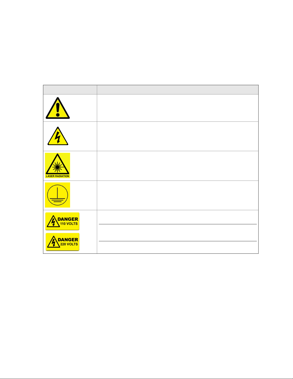
Symbols displayed on and inside the detector
To minimize risk, labels displaying warning signs are fixed to the transmitter. You must
understand their meaning, take suitable precautions, and read all instructions given in the
accompanying manuals before conducting any operations.
The following table gives examples and definitions of each symbol used.
Symbol Definition
General warning
Refer to instruction manual before proceeding.
Danger electricity
Make sure that the system is disconnected from all electrical power supplies prior to opening
doors or removing covers.
Laser radiation
Earth (ground) identification
AC power supply
Note
The label shown is for illustration only. It is possible that the image will show a voltage in the range of
100 to 240 Vac.
Page 11

Contents
Contents
Chapter 1 Leak detection overview ................................................................................................ 1
1.1 System overview ..........................................................................................................................2
Chapter 2 Equipment and accessories ............................................................................................ 3
2.1 Typical installation ....................................................................................................................... 3
2.2 System connections .....................................................................................................................4
2.3 Typical sample head .................................................................................................................... 6
2.4 Air preparation plate ....................................................................................................................7
2.5 Upper enclosure .......................................................................................................................... 8
Chapter 3 Installation .....................................................................................................................9
3.1 Installation requirements .............................................................................................................9
3.2 Installation instructions ............................................................................................................. 12
Chapter 4 Startup .........................................................................................................................17
Chapter 5 Shutdown .................................................................................................................... 19
Chapter 6 Operation .................................................................................................................... 21
6.1 Leak detector manager (LDM) software ..................................................................................... 22
6.2 Data logging and reporting ........................................................................................................25
6.3 Status lamps / errors .................................................................................................................. 27
6.4 Line stop .................................................................................................................................... 29
6.5 PLC configuration screen ........................................................................................................... 30
Chapter 7 Maintenance ................................................................................................................33
7.1 Scheduled maintenance ............................................................................................................ 33
7.2 Clean cell mirrors ....................................................................................................................... 33
7.3 Air filter ......................................................................................................................................35
7.4 Control system .......................................................................................................................... 37
7.5 Sample head ..............................................................................................................................37
7.6 Recommended spare parts ........................................................................................................ 37
Chapter 8 Troubleshooting and diagnostics ................................................................................. 39
Appendices and reference
Appendix A Specifications ...............................................................................................................43
Reference Manual i
Page 12

Contents
ii Rosemount CT4215
Page 13

1 Leak detection overview
Gas concentrations are measured using mid-infrared optica absorption spectroscopy. The
light sources are Quantum Cascade Lasers (QCLs), which are operated to produce
wavelength sweeps that cover the absorption lines of the target gases.
The laser is mounted in the baseplate between the upper and lower enclosures of the leak
detector, and light is directed through the measurement cell and onto a detector. When
molecules from a leaking container enter the measurement cell, they partially absorb the
laser light. The variation in the intensity of the light indicates a leaking container, and the
container is rejected from the line.
The leak detector identifies packaged products that have a break in seal integrity as they
are carried along a conveyor belt at speed. The leak detection system consists of a
sampling head which draws air from around the product. The air is passed through the
measurement cell for high speed analysis.
Leak detection overview
Reference Manual 1
Page 14
Leak detection overview
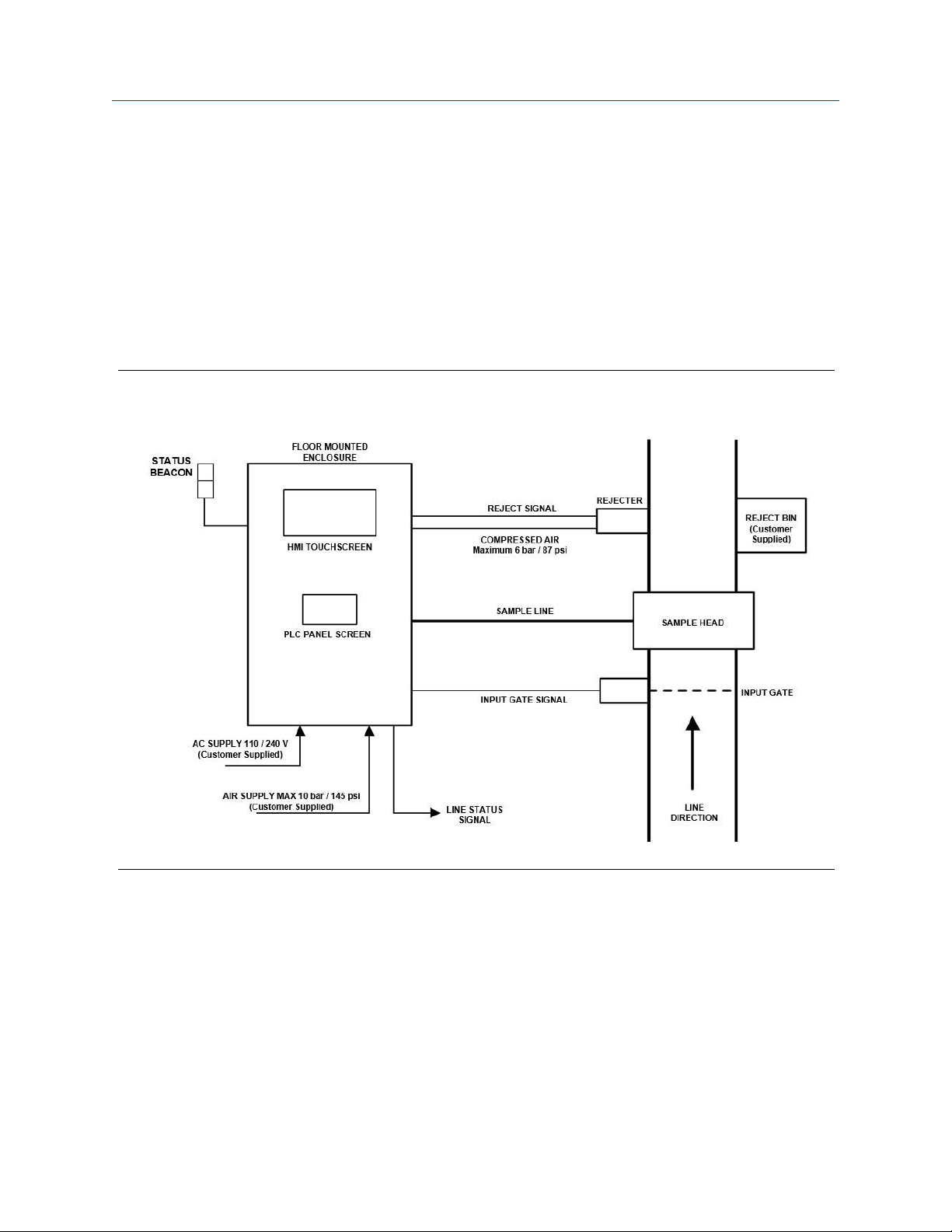
1.1 System overview
The Rosemount™ CT4215 Leak Detector is used on packaged lines and comprises an all
metal enclosure containing the Quantum Cascade Laser (QCL) analyzer, PLC control,
compressed air preparation, and vacuum. The external component may include light
gates, sample head, and a rejection mechanism to safely remove defective products from
the line.
Figure 1-1 shows the leak detection system.
Leak Detection System Block DiagramFigure 1-1:
2 Rosemount CT4215
Page 15

2 Equipment and accessories
2.1 Typical installation
Figure 2-1 shows a typical installation for a Rosemount™ CT4215 on a food handling line.
Rosemount™ CT4215 PartsFigure 2-1:
Equipment and accessories
A. Sample head1: draws air from around the packaged product into the measurement cell.
B. Analysis cell: the laser beam and sample gas pass through here for analysis.
C. Electronics: laser, detector, PLC, and DC power supply.
D. Air preparation: compressed air must be filtered and dried for optimum performance.
E. Vacuum pump: high flow rate pump for fast sample delivery to measurement cell.
F. Reject mechanism2: compressed air reject mechanism.
G. Touchscreen HMI: user interface for system.
H. PLC panel screen: screen set to certain PLC parameters. This will be locked to operators under
normal operation.
1. Sample head is modular and may differ depending on application.
2. May differ depending on application.
Reference Manual 3
Page 16
Equipment and accessories
2.2 System connections
Figure 2-1 shows a typical installation for a Rosemount™ CT4215 on a food handling line.
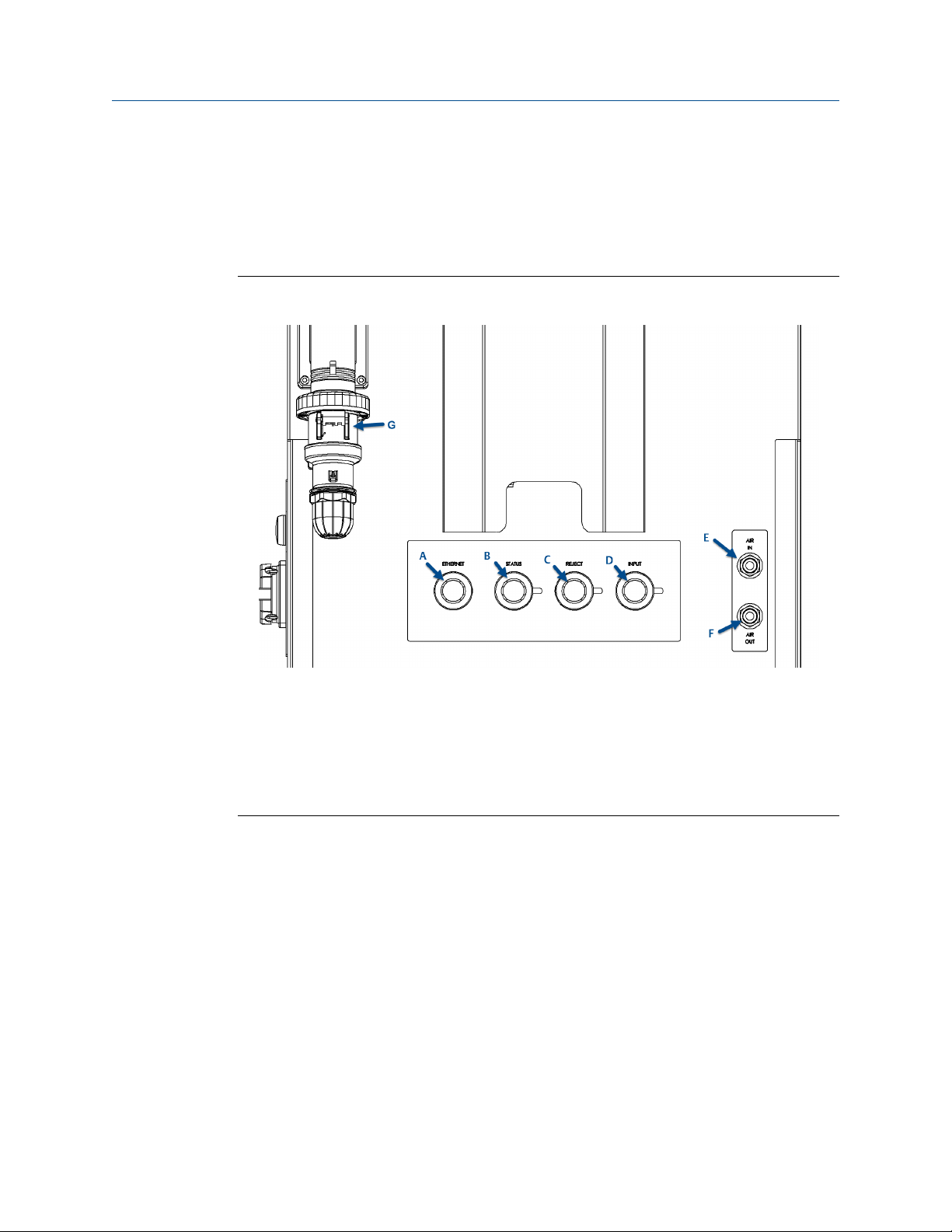
Figure 2-2 shows the external connections of the packaged leak detection system. These
are located at floor level on the rear of the unit.
External ConnectionsFigure 2-2:
A. Ethernet
B. Status, 24 Vdc (line stop)
C. Reject
D. Input gate
E. Air in
F. Air out
G. Mains supply
4 Rosemount CT4215
Page 17

Equipment and accessories
External ConnectionsTable 2-1:
Letter Designation Type Max rating Description
A Ethernet RJ45 Ethernet N/A Communication with
sensor
B Status, 24 Vdc (line stop) Bulgin 4P female 250 Vac/dc, 6 A Customer supplied 24 V
signal when line is running. Rosemount
CT4215 health status is
returned (see
Section 6.4).
C Reject Bulgin 3P female 250 Vac/dc, 10 A 24 V signal to the rejec-
tion solenoid when a defective pack is detected.
D Input gate Bulgin 4P female 250 Vac/dc, 6 A Gate signal to the sensor
to count incoming
packs.
E Air in 8 mm push fit 10 bar (145 psi) Customer supplied com-
pressed air
F Air out 8 mm push fit 6 bar (90 psi) Regulated compressed
air for accessories, i.e.,
rejection
G AC supply Mennekes right angle
2P+E
Yellow: 110 - 130 V
Blue: 200 - 250 V
Customer supplied
mains
16A
™
Reference Manual 5
Page 18

Equipment and accessories
2.3 Typical sample head
The sample head is used to draw air from around the product and deliver it to the
measurement cell.
To ensure a high air flow rate, the sample head is connected to the leak detector using a ¾in. hose, shown in Figure 2-3. There is a central roller with a sample head at either side.
Note
The sample head shown is for food packaging; this may change depending on the product/
production line.
Sample Head (Closed)Figure 2-3:
WARNING!
CRUSH AND CUT HAZARD
Moving parts can crush and cut.
Do not operate with the sample head open.
Failure to observe this warning may cause serious injury to personnel.
6 Rosemount CT4215
Page 19

2.4 Air preparation plate
The customer supplied compressed air is filtered to remove impurities and is pressureregulated.
The assembly shown in Figure 2-4 is mounted inside the leak detector control system
cabinet.
Compressed Air Preparation PlateFigure 2-4:
Equipment and accessories
A. Shut off valve
B. Pressure regulator with 40 µm filter
C. 0.1 µm filter
D. Pressure switch (MPa)
E. Membrane dryer
F. Solenoid switch
Reference Manual 7
Page 20

Equipment and accessories
2.5 Upper enclosure
The upper enclosure is accessible with an 8 mm Allen key and comprises the following
components shown in Figure 2-5. The upper enclosure is the main area for maintenance
access (see Chapter 7).
Upper enclosureFigure 2-5:
A. Measurement cell with insulating jacket
B. Manual purge button
C. Cell lid clamps
D. Cell input mirror, directs laser into cell
E. Cell output mirror, directs laser onto the detector
8 Rosemount CT4215
Page 21

3 Installation
3.1 Installation requirements
The customer provides the following:
Installation RequirementsTable 3-1:
Customer provided Specification
Mains supply (defined by customer) 110/120 Vac, 50 Hz
or
Mains supply (defined by customer) 220/240 Vac, 60 Hz
Circuit breaker 16A (maximum)
Mounting Affix to floor or building structure
Compressed air 8-10 bar / 115 - 145 psi
Installation
For the electrical power wiring, use 16 AWG stranded, three conductor copper plain or tin
plated wire, rated for a minimum of 250 Vac for the required cable length. Cables must be
terminated in accordance with national/local electrical standards and must be rated for
operation in ambient temperatures > 176 °F (80 °C).
Emerson™ does not supply a switching system with the instrument. The customer must
supply a suitably rated switch or circuit breaker to be included with this installation. Check
the installation of the switch for conformity in accordance with national/local regulations
and standards by inspection. The switch or circuit breaker must be suitably located, easily
reached, and identified as the disconnection device for the leak detection system.
The leak detection system provides a protective earth terminal. To prevent electrical shock
hazards, connect the instruments to a protective earth. Any interruption of the earth
connector inside or outside the instrument or disconnecting the earth terminal may cause
potential electrical shock hazard.
Reference Manual 9
Page 22

Installation
Line Installation LocationFigure 3-1:
Ground FixingFigure 3-2:
10 Rosemount CT4215
Page 23

Installation
Installation of Reject MechanismFigure 3-3:
Sample Head InstallationFigure 3-4:
Reference Manual 11
Page 24

Installation
3.2 Installation instructions
Only Rosemount™ Customer Care Representatives should install this instrument.
WARNING!
LIFTING HAZARD
The system weighs 268 lb. (119 kg). Beware of collision injury and topple injury when moving.
Emerson™ recommends using a forklift to move the system.
WARNING!
CRUSH HAZARD
Be careful not to crush hands and feet when moving the system.
WARNING!
DRILL INJURY
Be careful to avoid injuring hands and eyes when drilling. Wear correct personal protective
equipment (PPE) at all times.
Procedure
1. Place the delivery crate in an open and easily accessible area, close to where the unit
will be assembled and installed.
2. Remove the instrument from the crate.
a. Remove the fixing screws (marked in red) from the front panel of the crate and
the front panel section. Place the front panel section from the crate in a safe
place well away from the working area.
b. Release the two straps located on the unit upright section.
c. Carefully remove the unit from the crate.
d. Remove all additional parts from the crate and place them to the side of the unit.
3. Ensure that all additional parts shown are present after unloading the crate.
Required parts are shown below.
Rosemount
Item Description Quantity
A Reject assembly 1
B Light gate assembly 1
C Sample head 1
D Hardware kit 1
™
CT4215 Installation PartsTable 3-2:
4. Place the unit enclosure at the desired position on the product line.
12 Rosemount CT4215
Page 25

Installation
Line Installation LocationFigure 3-5:
5. Ground the instrument.
a. Lower the feet to the ground.
b. Raise the unit a few inches off the ground.
c. Remove the wheel brackets.
d. Lower the unit to the floor.
e. Use the feet to level of unit if required.
f. Bolt the unit to the floor as per site standards.
Reference Manual 13
Page 26

Installation
Ground FixingFigure 3-6:
Refer to the fastener manufacturer's guide for fixing instructions and torque.
g. Place the cap covers over the access holes.
6. Attach the light gate to the track.
a. Drill the location hole(s) into the track side faces in the approximate positions
required for input gate.
Use track location T slots if available (no drilling required).
b. Place the light gate in the required position on the track using the fasteners
supplied in the hardware kit. Hand tighten the fasteners only at this time.
WARNING!
DRILL INJURY
Be careful to avoid injuring hands and eyes when drilling. Wear correct PPE at all
times.
c. Adjust the angle and height of the light gate to suit the package being scanned.
d. Secure the light gate in place using the fasteners fitted previously.
e. Torque the fasteners to 7.6 Nm (5.6 ft.-lb.).
14 Rosemount CT4215
Page 27

7. Attach the reject mechanism.
WARNING!
DRILL INJURY
Be careful to avoid injuring hands and eyes when drilling. Wear correct PPE at all times.
a. Drill two location holes into the track side face in the approximate positions
required for the reject mechanism.
Use track location T slots if available (no drilling required).
b. Attach the reject mechanism on the track in the approximate position required
using two M6 socket head cap screws, two spring washers, and two washers.
c. Leave the reject mechanism loose by hand tightening the fasteners only.
d. Secure the reject mechanism in place using previously fitted bolts.
e. Torque fasteners to 5.6 ft-lb. (7.6 Nm).
f. Adjust the angle and depth of the the reject mechanism as required. Loosen the
side bolts to adjust the angle and then tighten them when aligned.
Installation
8. Attach the sample head.
WARNING!
DRILL INJURY
Be careful to avoid injuring hands and eyes when drilling. Wear correct PPE at all times.
a. Drill four location holes into the track side face in the approximate position
required for the sample head.
Use track location T slots if available (no drilling required).
b. Place the sample head on the track in the approximate position required using
four M6 socket head cap screws, two spring washers, and two washers.
c. Leave the sample head loose by hand tightening the fasteners only.
d. Secure the sample head in place using previously fitted fixings.
e. Torque fasteners to 5.6 ft-lb. (7.6 Nm).
f. Adjust the sample head height to the track as required to suit pack thickness.
Loosen side bolts to adjust the height on the slots and then tighten them when
aligned to the required pack height.
Reference Manual 15
Page 28

Installation
16 Rosemount CT4215
Page 29

4 Startup
The Leak Detection System must be installed and fully commissioned by qualified
Rosemount™ personnel prior to customer operation.
1. Turn the unit isolator switch (shown below) to the ON position.
Once power has been started, the system takes approximately two minutes to boot.
Startup
Isolation SwitchesFigure 4-1:
2. Ensure the compressed air supply is open.
3. When production begins, turn the blower isolator to the ON position.
NOTICE
Emerson™ recommends that the blower is switched off when the production line is not
running. This will extend the lifetime of the sample air filter.
4. Press the Reset button on the front of the console and ensure there is a green light
on the beacon.
Reference Manual 17
Page 30

Startup
18 Rosemount CT4215
Page 31

5 Shutdown
Complete the following steps to safely shut down the system when it is not in use.
CAUTION!
EQUIPMENT DAMAGE
Failure to follow the correct shutdown procedure may damage the instrument. Only use the
isolation switch on its own to shut down the system in an emergency as a last resort to remove
power from the system.
Procedure
1. Press the PowerDown button at the upper right corner of the human machine
interface (HMI).
Shutting Down the SystemFigure 5-1:
Shutdown
This shuts down the HMI.
2. Turn the unit isolator to the OFF position.
Reference Manual 19
Page 32

Shutdown
NOTICE
Turning the unit isolator switch to OFF switches the system off. At this point, mains
voltage is still applied inside the enclosure. Before opening the packaged Leak Detection
System, isolate the mains to the enclosure at the mains supply.
3. Close the compressed air supply if required.
20 Rosemount CT4215
Page 33

6 Operation
The packaged Leak Detection System is designed to run autonomously with minimal user
interaction required. After the startup procedure in Chapter 4, the system needs only a
green light to run.
There are up to three components mounted onto the packaged production line. The
layout of the line is shown schematically in Figure 6-1.
Schematic Layout of the System On LineFigure 6-1:
Operation
The packs flow on the schematic above from left to right. The packs pass through the input
gate which is located before the sample head. A space of at least 1 in. (2.5 cm) is required
between packs in order to ensure correct counting and rejection. A space of at least 6 in.
(15.2 cm) is advised for best operation.
The sample head then analyzes the pack/container.
The reject mechanism safely removes faulty containers from the production line without
the need to stop the line. The distances between the components is set at the time of
install and is determined by the speed of the production line.
Reference Manual 21
Page 34

Operation
6.1 Leak detector manager (LDM) software
The LDM software is designed to give clear information at-a-glance.
LDM Home screenFigure 6-2:
A. Start/Stop Monitoring: Automatically starts monitoring during startup. Pressing the button again
will pause the system and stop measuring.
B. Configure: Accesses the settings and parameters of the system and is password protected.
C. Reset Alarms: Clears alarms and resets status alarms to green.
D. Reset Counters: Returns the counters to 0.
E. Reports: Accesses the logging features of the system. Use a USB to log and export production
statistics and rejection data.
F. Power Down: Safely shuts down the HMI.
G. Outputs: Explained in Section 6.3.
H. Counters
I. Tab selection: Toggle between the three tabs to change which visual information is displayed.
A. Pulse: Displays the laser pulse amplitude in volts (see Figure 6-2).
B. Concentration: Displays the CO2 measurement plot and shows a spike for a leaking pack (see
Figure 6-3).
C. UNIT: Displays the measurement plot between the gates, refreshing for each pack (see
Figure 6-4).
22 Rosemount CT4215
Page 35

Operation
Concentration TabFigure 6-3:
Figure 6-3
shows the Concentration tab with one leaking package passing through. When
the blue line reaches the upper threshold (red line), the sensor sends a rejection signal to
the PLC and then the rejection solenoid to remove the faulty pack from the line. The lower
threshold is typically approximately 80 percent of the upper threshold and prevents the
system from missing a marginal leak.
Reference Manual 23
Page 36

Operation
UNIT TabFigure 6-4:
Figure 6-4
shows the UNIT tab when a leaking pack has passed through. The plot shows all
data points between the input and output gate and records the size of the rejection spike.
24 Rosemount CT4215
Page 37

6.2 Data logging and reporting
The system can store production statistics like packs processed and number of rejects. This
can be transferred from the HMI on a USB stick to be analyzed elsewhere.
To enable the Reporting screen, click the Reports tab. The Reporting screen is password
protected, and the password will be supplied or changed during installation.
Reports Popup WindowFigure 6-5:
Operation
A. Enable/Disable Reports: Turn reporting on or off.
B. Delete Report: Delete a file from a specified location.
C. Create report: Set the file name and save location.
D. Save Report: Save the current file to a specified location.
E. Copy Report File: Move a file from one location to another.
Note
The file must be saved as <filename>.txt
You can export the .txt report file to a USB stick and process it elsewhere. If you open the
file using Microsoft® Excel or a similar program, it will look like the example below.
Reference Manual 25
Page 38

Operation
Sample Report FileFigure 6-6:
• Client/Product/Batch: These are entered during the creation of the log file.
• Date/Time: The timestamp for each unit; this is set by the PC.
• Leak (abs): The maximum concentration value for each unit. If this value is greater than the upper
threshold, this package will be rejected.
• Leak (cal): For certain applications, a calibration factor may be applied in order to have units for
leakage (i.e., bubbles/second or mg/day).
• UT: The upper threshold value. If the concentration exceeds this value, the package is rejected.
• LT: The lower threshold: If two consecutive concentration points exceed this value, the package is
rejected.
• Noiselevel: the noise value at the time when the package is logged.
• Reject: Packages which do not breach thresholds are reject = 0, and those which breach
thresholds are reject =1.
Note
If you want to view only rejected packages, then filter column H to show only rows with 1 in them.
NOTICE
The CanInfo type is logged for all units processed; the Reject type only shows the reject value.
26 Rosemount CT4215
Page 39

6.3 Status lamps / errors
There are a number of errors that the Leak Detection System monitors, which may occur
during the normal operation of the system. The errors are displayed as an illuminated lamp
on the front of the enclosure. All errors latch and are cleared by the RESET button on the
front of the enclosure. The errors are detailed below and, when activated, will trigger the
red beacon bulb and line stop (if applicable).
Cabinet Status IndicatorsFigure 6-7:
Operation
A. Alarm beacon: Green for healthy; red for unhealthy/line stop.
B. RESET button to clear latched alarms.
C. AIR status bulb. Illuminates when blower or compressed air is off.
D. Blower status: A status bulb turns on when power is supplied to the blower. If the power is
interrupted, the bulb doesn't turn on, and the AIR warning bulb turns on.
Reference Manual 27
Page 40

Operation
LDM Software ErrorsFigure 6-8:
1. System Ready: Shows when the system is ready for use. This is red during system
start up.
2. System Healthy: The system can become unhealthy if the gate in/out count is
different or if there have been n consecutive rejects (the default value is five
consecutive rejects). Press Reset counters on the HMI to clear the error.
3. Laser Healthy: The laser becomes unhealthy if it is below the threshold value (see the
red line in Figure 6-2). Check the beam path for obstruction or clean the cell mirrors
as described in Section 7.2. This error automatically clears when the pulse amplitude
is above the threshold.
4. Maintenance: The yellow warning triangle appears if the laser pulse amplitude is
below the warning threshold value. System performance is not affected, but you
should consider activating the mirror purge or cleaning the cell mirrors soon. This
error automatically clears when the pulse amplitude is above the warning threshold.
5. Too many Consecutive Rejects: If several packs are rejected in a row, this error is
triggered. Figure 6-9 shows the error message generated. To reset this error, press
the Reset Alarms button on the touch screen.
28 Rosemount CT4215
Page 41

Operation
Consecutive Rejects ErrorFigure 6-9:
6.4 Line stop
The control system provides a signal that can stop the production line if there are errors on
the system.
The signal is sent to the STATUS connector shown in Figure 2-2. The connection is a voltfree contact and can be configured in Normally Closed (NC) and Normally Open (NO) from a
customer supplied 24 V.
Line Stop Plug Pin NumberingTable 6-1:
Normally Closed (NC) 1 2
Normally Open (NO) 3 2
The overall system is high when healthy (green light) and low when unhealthy (red light).
24 V line 0 V line
Reference Manual 29
Page 42

Operation
6.5 PLC configuration screen
CAUTION!
EQUIPMENT DAMAGE
The PLC settings directly control the analysis and rejection of defective containers. Only trained
personnel should change the settings listed below. The PLC screen has password protection in
order to prevent unauthorized access. The credentials are provided to the relevant department
during installation. Following any change to line speed, pack size, or pack spacing, qualified
personnel should verify the system.
The system is designed to accommodate changes in pack size and line speed. There are
five configurable parameters highlighted in red below.
PLC Configurable ParametersFigure 6-10:
The PLC screens are shown in Figure 6-11 with an explanation of each button in Table 6-2.
PLC Configuration ScreensFigure 6-11:
30 Rosemount CT4215
Page 43

PLC Configuration ParametersTable 6-2:
Parameter name Description Range
Pack Length The length of time a pack takes to pass
the input gate. This timer is a debounce to prevent double counting of
uneven packs.
Measurement Start The delay between the pack passing
the input gate and the sensor counting it IN and beginning analysis.
Measurement End The delay between the pack being
counted in and the sensor finishing
analysis. This ensures complete inspection from leading edge to trailing
edge. This also generates the pack
OUT count on the software screen.
Reject Delay The time between the bag being
counted OUT and the rejection mechanism.
Reject Duration The length of time for which the rejec-
tion solenoid is open for rejection.
0 - 2000 ms
0 - 9000 ms
0 - 10000 ms
60000 ms (1 minute)
10000 ms
Operation
Reference Manual 31
Page 44

Operation
32 Rosemount CT4215
Page 45

7 Maintenance
The packaged Leak Detection System is inherently reliable at reducing the requirement for
routine maintenance. This section provides information on the schedule of maintenance
you should perform to ensure the reliable performance of the system.
WARNING!
ELECTRIC SHOCK
For all maintenance inside the lower section of the console, the system must be powered off
using the shutdown procedure detailed in Chapter 5. Inside the console there are potentially
dangerous voltages.
7.1 Scheduled maintenance
The maintenance activities and their related frequencies are shown below.
Maintenance
7.2 Clean cell mirrors
Follow the steps below to clean the cell mirrors in the Rosemount™ CT4215.
CAUTION!
EQUIPMENT DAMAGE
The cell mirrors are an optical device; only clean them when required. Avoid over cleaning the
mirrors. Use only the cleaning parts listed in this document.
If the laser pulse amplitude drops below the laser warning threshold (default 0.4 V), then
the yellow Maintenance warning message appears on the HMI (Figure 7-1).
Figure 7-1:
The system performance is not affected and runs as normal, but consider purging the cell
or prepare to clean the cell mirrors soon.
Error Message for Pulse Amplitude below Warning Threshold
Reference Manual 33
Page 46

Maintenance
If the laser pulse amplitude drops below the laser threshold (default 0.2 V), the Laser
Healthy alarm turns red, and the LASER bulb on the front of the control system is red. At
this point, the line stops, because of the red light; clean the mirrors.
Error Message for Pulse Amplitude below ThresholdFigure 7-2:
Procedure
1. Switch off the BLOWER ISOLATOR and compressed air supply.
2. Open the upper enclosure to see the red measurement cell jacket.
3. Release the two clamps on top of the cell lid.
4. Remove the top cover of the cell jacket.
5. Remove the black cell cover.
6. Use only Thor Labs lens cleaning tissue (P-5000-0613) to gently wipe the mirrors on
each side of the cell (see Figure 7-3).
CAUTION!
EQUIPMENT DAMAGE
Avoid skin contact with the mirrors as oils can be deposited.
Cleaning the Cell MirrorsFigure 7-3:
34 Rosemount CT4215
Page 47

7. Once the mirrors have been cleaned, check the pulse amplitude on the HMI and
ensure it is > 0.4 V, resetting any alarms.
8. Replace the black cell lid, red cell cover, and clamps.
9. Switch on the BLOWER ISOLATOR and press the Purge button for a few short bursts.
10. Clsoe the upper enclosure and reset any alarms.
7.3 Air filter
The air filter is located externally at the rear of the upper enclosure and prevents dust and
debris from reaching the cell. Emerson™ recommends inspecting the filter at monthly
intervals. The steps below show how to access the air filter for inspection or changing.
1. Isolate the blower so that there is no air flow through the filter and cell.
2. Using circlip pliers, remove the circlip from the end of the filter housing, Figure 7-4.
Maintenance
Removing the Circlip from the Filter HousingFigure 7-4:
3. Remove the end fitting from the filter housing, taking care not to damage the O-ring
or the filter housing in the process, Figure 7-5.
Reference Manual 35
Page 48

Maintenance
Removing the End Fitting from the Filter HousingFigure 7-5:
4. Remove the filter for inspection/cleaning or replacement, Figure 7-6.
Retain the O-ring.
Removing the Filter from the Filter HousingFigure 7-6:
36 Rosemount CT4215
Page 49

7.4 Control system
The leak detector system is inherently tolerant to high levels of contamination/dust
without a reduction in performance.
Depending on the factory cleaning regulations, wipe down the control cabinet with
suitable cleaning products as required. Emerson™ recommends doing this monthly.
7.5 Sample head
The sample head comes into contact with packages, so it should be cleaned and inspected
in line with the factory standards. Only clean the sample head when the system is switched
off, compressed air is off, and the conveyor is off.
7.6 Recommended spare parts
The following parts are available from Emerson™.
Maintenance
Spare PartsTable 7-1:
Part number Part description
P-6000-00358 Valve, solenoid
P-6000-00357 Filter/regulator, 40 m
P-6000-00355 Filter 0.01 m
P-6000-00495 Lens cleaning tissue (pack of 5)
B-6000-0007-C PCB, digitiser, Mk5
E-4004-6002-B PCB, motherboard
E-4004-6001-D PCB, pulse module
E-4001-9001-B PCB, opto
M-3000-0936 Assy Assy, cell mirror
M-3000-1367-B Assy, pneumatic plate
P-6001-00052 Module, detector
P-6000-00139 Relay, 110 Vac
P-6000-01303 Blower, side channel
B-6000-0007-C PCB, digitiser
Reference Manual 37
Page 50

Maintenance
38 Rosemount CT4215
Page 51

Troubleshooting and diagnostics
8 Troubleshooting and diagnostics
The Rosemount™ CT4215 leak detection system is designed to run unattended and to
recover from system issues where possible. This section is designed to assist in the
identification and solution of potential problems. If in doubt, contact Rosemount
customer services for clarification on solutions before continuing.
Possible Problems and SolutionsTable 8-1:
Fault symptom Order of troubleshooting Action or item to be replaced
System is not switching on. Check the mains power is connected
and on at the supply. (There may be a
customer-provided circuit breaker fitted in a nearby cabinet).
Check the system isolator is set to the
ON position.
Check the 12/24 V MCBs Q1/Q2 have
not tripped.
Check inside AC distribution box.
Laser pulse is not displayed. Check the network connection on the
motherboard for flashing LED.
Check the HMI ethernet for flashing
LED.
Check network switch hub for flashing
LED.
Check UDP addresses match in Config-
uration screen and Setup screen.
Check the laser ribbon cable. Reconnect the cable (do not hot plug
Check the detector ribbon cable and
SMA.
Concentration graph is not updating. Check the network connection on the
motherboard for flashing LED.
Check the HMI ethernet for flashing
LED.
Check network switch hub for flashing
LED.
Check UDP addresses match in Config-
uration screen and Setup screen.
Check the laser ribbon cable. Reconnect the cable (do not hot plug
Check the detector ribbon cable and
SMA (do not hot plug).
Reset customer MCB if tripped.
Switch the isolator ON.
Reset MCBs if tripped.
Default values for the UDP addresses
are 65501 and 65502.
if loose).
Reconnect the cable (do not hot plug
if loose).
Default values for the UDP addresses
are 65501 and 65502.
if loose).
Reconnect the cable (do not hot plug
if loose).
™
Reference Manual 39
Page 52

Troubleshooting and diagnostics
Possible Problems and Solutions (continued)Table 8-1:
Fault symptom Order of troubleshooting Action or item to be replaced
Maintenance alarm on LDM. If the pulse is below the LASER warn-
ing threshold, consider purging the
cell with compressed air.
Note
The system will still be healthy.
Purge the cell.
Consider cleaning the cell mirrors
soon when pulse is below threshold.
Laser unhealthy. If the pulse is below the laser thresh-
old, clean the cell mirrors.
Check the laser beam path for obstructions.
System unhealthy. If the pulse is below the laser thresh-
old, clean the cell mirrors.
Check the laser beam path for obstructions.
If the system has rejected n consecutive rejects, press the Reset alarms
button on LDM.
If the IN/OUT count does not match,
reset the counters.
AIR warning light illuminated. Check the blower isolator is in the ON
position and the blower status bulb is
illuminated.
Check the compressed air supply is
open.
Check the compressed air supply pressure is within the specified range of
the pressure switch (0.3 - 0.5 MPa).
Pressure switch should be green.
Traffic light is red and does not reset
to green when Reset pressed.
System is not counting packs. Check the INPUT gate cable is attach-
Check if the LDM dasboard is green. Repeat the rows Laser unheathy and
Check if the AIR warning light is illuminated.
ed at both ends: control system and
light gate.
Clean the mirrors.
Clean the mirrors.
Clear any obstructions from the laser
beam path.
Clean the mirrors.
Clear any obstructions from the laser
beam path.
Press the Reset button (see
Section 6.3).
Reset the counters.
Switch the isolator ON.
Turn on the air.
Confirm the supply pressure. (See
Section 2.4 for location of the pressure
regulator).
System unhealthy above.
Repeat the row AIR warning light illuminated above.
Attach the cable (do not hot plug if
loose).
40 Rosemount CT4215
Page 53

Troubleshooting and diagnostics
Possible Problems and Solutions (continued)Table 8-1:
Fault symptom Order of troubleshooting Action or item to be replaced
Check that the orange LED is flashing
on the light gate when a pack enters
the system.
Gate sensitivity can be adjusted using
the dial on the light gate. It should
flash orange when the beam is broken
at a distance of approximately 20 to
200 mm.
Reference Manual 41
Page 54

Troubleshooting and diagnostics
42 Rosemount CT4215
Page 55

Appendix A
Specifications
The following table shows the general characteristics of the Leak Detection System.
System SpecificationsTable A-1:
Item Measurement Notes
Control enclosure
Dimensions 33 x 23 x 69 (74) in.
840 x 588 x 1743 (1900) mm
Weight 268 lb.
119 kg
Sample head
Dimensions 19 x 20 x 13 in.
480 x 500 x 320 mm
Weight 30.9 lb.
14 kg
Depth x width x height (top of beacon)
Depth x width x height
Specifications
Detectable gases
Standard Ethanol - drinks
Specify on order CO2 - food
Environment
Air temperature 23 to 86 °F
-5 to 30 °C
Humidity range 10 to 95% Relative humidity (non-condensing) at
Production line area services required
System operating voltage 110/240 Vac, 50/60 Hz Specify on order
System power consumption 600 W Maximum power requirement
Factory air supply 116 psi to 145 psi
8 to 10 Bar
Line space requirement 3.9 ft.
1.2 m
Air filter particulate filter 5 µm Inline filter
Ambient
95 °F (35 °C)
Clean, dry, and oil free
Standard free line (approximate, dependent on line speed)
Reference Manual 43
Page 56

00809-0100-4245
Rev AB
2018
CASCADE TECHNOLOGIES
Castle Business Park
Stirling FK9 4TZ
Scotland
+44 1786 447 721
+44 1786 475 822
cascade.support@emerson.com
EUROPE
Emerson Automation Solutions
Neuhofstrasse 19a PO Box 1046
CH-6340 Baar
Switzerland
T +41 (0) 41 768 6111
F +41 (0) 41 768 6300
cascade.support@emerson.com
Linkedin.com/company/Emerson-Automation-Solutions
twitter.com/rosemount_news
Facebook.com/Rosemount
youtube.com/RosemountMeasurement
google.com/+RosemountMeasurement
AnalyticExpert.com
GLOBAL HEADQUARTERS
Emerson Automation Solutions
6021 Innovation Blvd
Shakopee, MN 55379, USA
+1 800 999 9307 or +1 952 906 8888
+1 952 949 7001
cascade.support@emerson.com
MIDDLE EAST AND AFRICA
Emerson Automation Solutions
Emerson FZE
Jebel Ali Free Zone
Dubai, United Arab Emirates, P.O. Box 17033
T +971 4 811 8100
F +971 4 886 5465
cascade.support@emerson.com
©
2018 Emerson. All rights reserved.
The Emerson logo is a trademark and service mark of Emerson Electric Co. Rosemount is a
mark of one of the Emerson family of companies. All other marks are the property of their
respective owners.
AMERICAS
Emerson Automation Solutions
8200 Market Blvd
Chanhassen, MN 55317
+1 800 999 9307
+1 952 949 7001
cascade.support@emerson.com
ASIA-PACIFIC
Emerson Automation Solutions
1 Pandan Crescent
Singapore 128461
Republic of Singapore
T +65 6 777 8211
F +65 6 777 0947
cascade.support@emerson.com
 Loading...