

Page 1

Quick Start Guide
MHM-97465
NC: 6540-90104
Rev.: 1.002
CSI 6500 Machinery Health™Monitor
A6151, Dual Channel Low Frequency Shaft Vibration Monitor
Page 2

Emerson Process Management
Machinery Health Management
835 Innovation Drive
Knoxville, TN 37932 USA
T 1(865) 675-2400
F 1(865) 218-1401
www.EmersonProcess.com
©2010, Emerson Process Management.
The contents of this publication are presented for informational purposes only, and while every effort has
been made to ensure their accuracy, they are not to be construed as warranties or guarantees, express
or implied, regarding the products or services described herein or their use or applicability. All sales are
governed by our terms and conditions, which are available on request.We reserve the right to modify or
improve the designs or specifications of our products at any time without notice.
All rights reserved. Machinery Health is a mark of one of the Emerson Process Management group of
companies. The Emerson logo is a trademark and service mark of Emerson Electric Co. All other marks are
the property of their respective owners.
Page 3
GB
Explanation of symbols
!
If this symbol is printed on a device, according to IEC 61010 it means that the
documentation of the device must be completely read and understood before
installation and commissioning of the device. All safety−related instructions
of this document must be observed. These safety−related instructions are
marked by the “STOP” symbol in this document.
If this symbol is printed on a device, according to IEC 61010 it means that this
device must be operated with DC voltage.
i
This symbol identifies text that contains important information.
!
Not following instructions identified with this symbol can result in functional
issues and incorrect measurements without damaging the machine.
STOP
Safety and warning instructions are identified with this symbol.
Failure to observe these instructions can result in material damage or
personal injury.
D
Symbolerklärung
!
Ist dieses Symbol auf einem Gerät angebracht, so sagt dies nach IEC 61010
aus, das es zur Installation und Inbetriebnahme des Gerätes zwingend
erforderlich ist, die Dokumentation des Gerätes vollständig gelesen und
verstanden zu haben. Sicherheitsrelevante Hinweise in dieser
Dokumentation sind unweigerlich zu beachten und im weiteren Verlauf dieser
Dokumentation durch das “STOP” Symbol (siehe unten) gekennzeichnet.
Ist dieses Symbol auf einem Gerät angebracht, so sagt dies nach IEC 61010
aus, dass es mit Gleichspannung betrieben wird.
i
Dieses Symbol kennzeichnet Textstellen, die wichtige Informationen
enthalten.
!
Hinweise, die bei Nichtbeachtung zu Funktionsstörungen und
Fehlmessungen führen, ohne das Gerät zu beschädigen, sind mit diesem
Symbol gekennzeichnet.
STOP
Sicherheits- und Warnhinweise sind mit diesem Symbol gekennzeichnet.
Die Nichtbeachtung solcher Hinweise kann zu Sachbeschädigungen oder
Personenschäden führen.
Page 4
Product Service Centers
America
Emerson Process Management
835 Innovation Drive
Knoxville, TN 37932
Tel: 865−675−2110
Fax: 865−218−1401
Brazil
Emerson Process Management Ltd.
Av Hollingsworth 325
Sorocaba, SP
BRAZIL 18087−000
Phone: 55 15 2383788
Fax: 55 15 22823300
Europe, Middle East, Africa
Emerson Process Management
div. ESAD
MHM Repair Center
Piestanska 1202/44
915 28 Nove Mesto nad Vahom
Slowakia
Tel: +421/32/7700 538
Fax: +421/32/7700 884
Asia
Emerson Process Management / Asia
Pacific Private Ltd.
3904 Room Central Plaza
18 Harbour Road Wan−Chai
Hong Kong
Tel: 852−2802−9223
Fax: 852−2802−8227
Incoming goods inspection
Check the content of the shipment to ensure that it is
complete; visibly inspect the goods to determine if the
device may possibly have been damaged during
transport. The following parts are included in the scope
of delivery and must be contained in the shipment.
1. A6151
2. Product information
If the contents are incomplete, or if any defects are
observed, a complaint must be filed with the carrier
immediately. Moreover, the responsible Emerson sales
organization must be informed to enable repair or
replacement of the device. Repairs or calibration that
may be required, are only possible at the Emerson
factory.
In this case, a non−detachable tag with customer name,
defect observed and version of the A6910 configuration
software must be attached to the device.
Repair and maintenance
During operation, monitors do not require any maintenance.
Repair or calibration of monitors is only possible at
Emerson.
i
The additional PCB (controller board)
is calibrated with the main board and
must not be replaced.
If work with the opened device on−site is
unavoidable, this should only be performed by a
specialist who is familiar with the associated
hazards.
STOP
Capacitors in the device can still be
energized, even if the device has
been disconnected from all power
sources.
Page 5

If repair or recalibration of a monitor is required, it
must be sent to Emerson. Attach a non−detachable
tag to the monitor with customer name, defect
observed and version of the A6910 configuration
software.
Guidelines for Returning Equipment to the
Product Service Center
If repair or calibration of a monitor is required, it must
be sent to Emerson.
Occasionally, concerns with CSI technology
hardware could arise. Should this happen, customers
under warranty or a current support agreement are
entitled to no−charge repairs.
Follow the checklist below to minimize return time
and ensure proper processing of your equipment.
Before returning any equipment to a Product Support
Center, please review this information:
1. Obtain a Return Materials Authorization (RMA)
number and the address of the appropriate
Product Service Center by calling 865.675.4274*.
Listen to the options for receiving an RMA. You
will be routed to support personnel who will
document your concern and give you an RMA
number if you are under support or warranty. If
your hardware is not under support or warranty,
you must have a Purchase Order for the amount
of the repair service before you can receive an
RMA number. Pricing for your repair can be
obtained from support personnel or by calling
your local sales representative. Once you have
your purchase order, call 865.675.4274* for an
RMA.
2. Once you have received your RMA, send your
hardware to the appropriate product service
center. Your hardware package should include:
G RMA Number (plus Purchase Order if
applicable)
G Description of the hardware
problem
G Return shipping address including a
phone number (No P.O. boxes).
G Any special request regarding the
return shipment.
G A list of the model numbers of each
item(s) being returned, along with
the serial number.
G Your name, address, telephone
number and email address.
G Company Name.
A form for completing this information has
been provided.
Make a copy of the form, complete all lines,
and return a copy in each return shipment.
Out of warranty? Need to get under
support? Get a customized quote for
bringing all your CSI technologies under a
support agreement:
Phone: 865.675.2400*, ext. 2130
Fax: 865.218.1478*
Email:
mhm.supportagreement@emersonproces
s.com
*Customers outside the Americas and
Canada: please refer to the list of service
centers and contact the service center near
you.
All rights are strictly reserved
Reproduction or divulgation in any form
whatsoever is not permitted without written
authority from the copyright owner.
Page 6

RMA Required Information
RMA number issued by Product
Service Center:
For all items beingreturned, please
list Model / Serial Number:
Are you under warranty or a current
support agreement (circle one)?
Yes No
If you answered no, what is your
purchase order number?
Company Name:
Contact Name:
Contact Address:
Contact Phone:
Contact Fax:
Contact Email:
Please describe the problem you are experiencing:
If we are to send the return shipment to someone other than the
Contact Name/Address above, please provide that address here,
including Contact Name and Phone Number:
Are there any special instructions regarding the return?
Please provide invoice address (if a purchase order was required):
Support customers − your instrument is shipped back to you the same
way that it is sent to our service center. For example, if you ship via
ground transportation, it is shipped back via ground.
Page 7

Page/Seite 7
Product Information / Produktinformation
A6151
1
GB
Shaft Vibration Monitor 9........................
1.1 Scope of Delivery 9...........................................
1.2 CSA Certification 10...........................................
1.3 CSA − Conditions of acceptability 10............................
1.4 Advice for Installation 10.......................................
1.5 Installation and Mounting 11...................................
1.5.1 Jumper RS 485 11..........................................................
1.5.2 Sensor raw signal 12........................................................
1.5.3 Installation 14..............................................................
1.6 Technical Data 14..............................................
1.6.1 Signal conditioning 14.......................................................
1.6.2 Channel monitoring 18......................................................
1.6.3 Limit value formation and alarms 19...........................................
1.6.4 Communication interfaces 20.................................................
1.6.5 Power supply 21............................................................
1.6.6 Environmental conditions 22.................................................
1.6.7 Mechanical structure 22.....................................................
2
D
Wellenschwingungsmonitor 23....................
2.1 Lieferumfang 23...............................................
2.2 CSA Zertifizierung 24..........................................
2.3 CSA − Akzeptanzkriterien 24....................................
2.4 Hinweis zur Installation 25......................................
2.5 Installation und Montage 25....................................
2.6 Technische Daten 28...........................................
2.6.1 Signalkonditionierung 28.....................................................
2.6.2 Kanalüberwachung 31.......................................................
2.6.3 Grenzwertbildung und Alarme 33.............................................
2.6.4 Kommunikationsschnittstellen 34.............................................
2.6.5 Spannungsversorgung 35....................................................
2.6.6 Umgebungsbedingungen 36..................................................
2.6.7 Mechanischer Aufbau 36....................................................
3 Connection Diagrams and Figures /
Anschlusspläne und Abbildungen 37....................
4 PI Revision List 41.....................................
Page 8

Page 8
Product Information / Produktinformation
A6151
Shaft Vibration Monitor
1
GB
SHAFT VIBRATION MONITOR
The two−channel Low Frequency Shaft Vibration Monitor A6151 is a module of the A6000
machine monitoring system. The micro−processor controlled monitor is used in conjunction with
two eddy current measuring chains to measure and monitor the relative shaft vibration of hydro
turbines.
The two channels of the monitor can be used as separate channels or they can be linked together
via the configuration. The following operating modes are possible:
• Dual channel operation.
• The calculation and output of the maximum value S
max
.
• The calculation and output of the greater vibration width S
PPmax
The characteristic values can be output via a 0/4 ... 20mA current output per channel
i
In this product information the mounting and electrical connection of the
monitor is described. The configuration of the A6151 is similar to the
configuration of the A6110. Hence additional information concerning
configuration and installation can be found in the operation manual of the
A6110 (order number: 6110−90001) This operating manual is part of the
configuration software CD. All differences in installation and configuration are
described in this product information.
To ensure the safe operation of the monitor and to permit setting of all
functions, it is indispensable to use only the latest versions of configuration
software (version 2.07 Beta 78) and operating manual.
The use of old operating manuals or configuration programs out of date may
lead to malfunctions or limitations of the measuring functions.
1.1 Scope of Delivery
The following parts are included in the scope of delivery and must be contained in the shipment:
• Low Frequency Shaft Vibration Monitor A6151
• This product information
Accessories (not included in delivery):
• MMS ParaKit (order no.: 9510−00027)
If the contents are incomplete or if is there any damage, so directly complain at the bearer. The
competent epro sales agency must be informed also, to enable repair or replacement for the
monitor. Repair or calibration of this instrument may only be made at epro.
Page 9
Page 9
Product Information / Produktinformation
A6151
Shaft Vibration Monitor
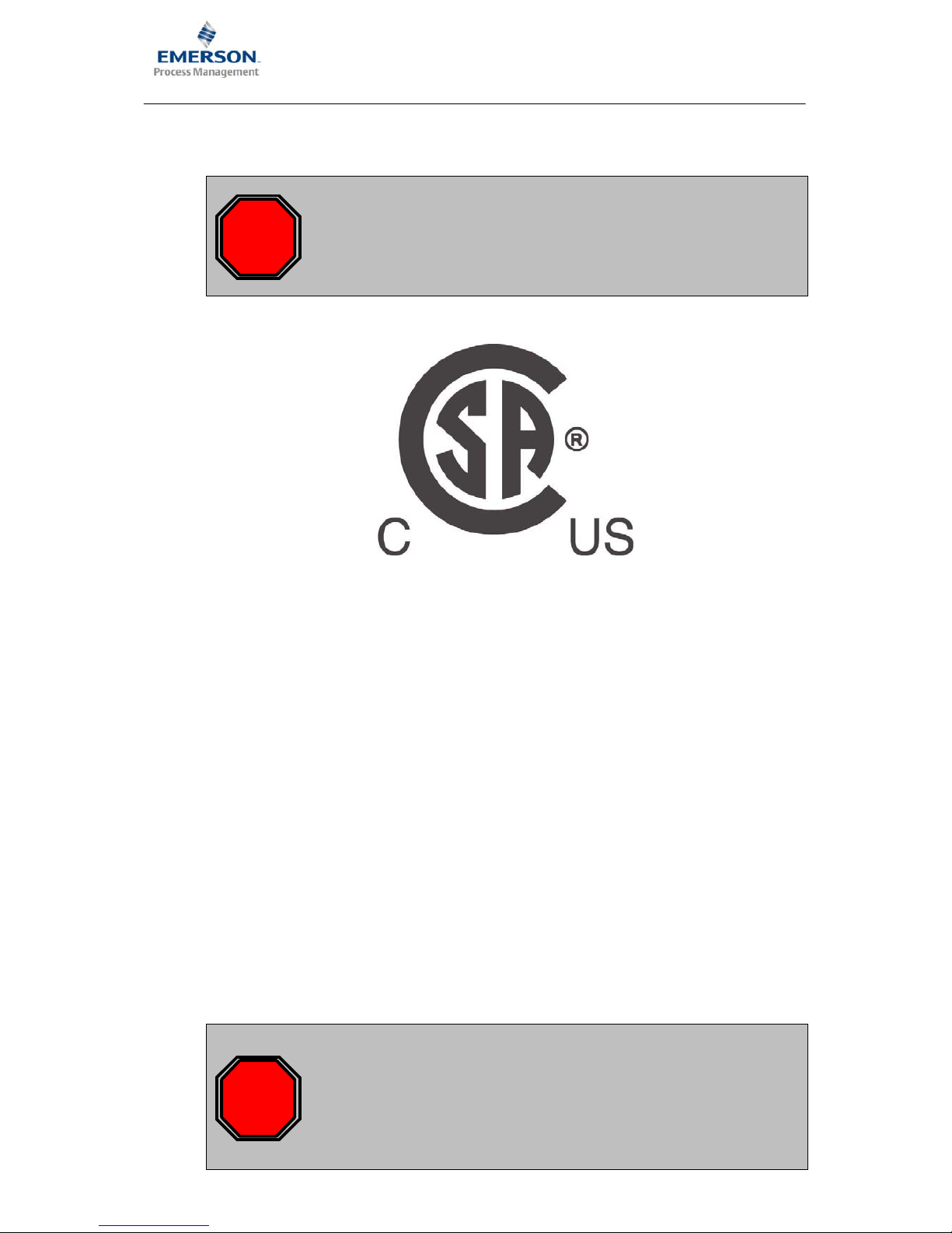
1.2 CSA Certification
STOP
For valid CSA certification, all devices (IMR 6000/xx and A6000 modules)
must be marked with the respective CSA lable.
If no CSA lable is available on the respective device, this device is not CSA
certified!
The respective CSA lable looks as shown in the following picture.
1.3 CSA − Conditions of acceptability
This device must be supplied with safety low voltage SELV LPS (C22.2 60950−1) 24V. The
voltage required for operation must be drawn from a separate power supply.
The system should be placed in a suitable fire enclosure.
The system is evaluated for an ambient Temperature of 0°C to 45°C.
Adequate ventilation space has to be provided so that heat does not build up. The ventilation
space must be at least 1 RU (1
3/4
inch) in all directions. If the ambient temperature of the rack
rises above 45 °C, cool this instrument with a forced air fan, cooler, or similar.
When mounting several IMR units above each other in one cabinet, install cooling fan racks in
between instead of the ventilation space. The necessary specifications for cooling fan racks
result from the environmental and sitting criterions of the cabinet and thus cannot be defined
generally.
1.4 Advice for Installation
STOP
According to the IEC 61010 directive, permanently installed systems must be
equipped with a power disconnect device (e.g. a switch or circuit−breaker
according to IEC60947−1 and IEC60947−3). When using an IMR rack, in
compliance with this directive, such a switch or breaker must be implemented
into the cabinet installation and easily accessible for the user. Furthermore,
each disconnect devices must be labeled in accordance to the associated
system.
Page 10
Page 10
Product Information / Produktinformation
A6151
Shaft Vibration Monitor
1.5 Installation and Mounting
A prepared 3U slot in a 19” rack, or other Intermas−compatible enclosure, is required for
mounting the A6151 monitor. The slot must be fitted with a 48−pin plug connector (DIN 41612,
design F 48 M). The pin assignment is listed in the following table.
d
b z
2
UN+ (+ 24V) U− (0V/Common) UB+ (+24V, redundant)
2
4
A (RS 485) GND (BP, Common, RS 485) B (RS 485)
4
6
Supply2+ (sensor) Supply1− (sensor) Supply1+ (sensor)
6
8
AIN2− (Input) Supply2− (sensor) AIN1− (Input)
8
10
AIN2+ (Input) GND AIN1+ (Input)
10
12
NGL2 (scaled dc−output) GND NGL1 (scaled dc−output)
12
14
EO1 (voltage output1) EI1 (voltage input1) AC1 (sensor raw signal1)
14
16
EO2 (voltage output2) EI2 (voltage input2) AC2 (sensor raw signal2)
16
18
GWM (limit value) I1− (current output common) I1+ (current output CH1)
18
20
NC I2− (current output common) I2+ (current output CH2)
20
22
KEY−N (key signal input) GND ES (external lock)
22
24
SC−A (oper. principle alert) GND SC−D (oper. principle danger)
24
26
D1−C (danger1 collector) A1−C (alert1 collector) CC1−C (ch. clear1 collector)
26
28
D1−E (danger1 emitter) A1−E (alert1 emitter) CC1−E (ch. clear1 emitter)
28
30
D2−C (danger2 collector) A2−C (alert2 collector) CC2−C (ch. clear2 collector)
30
32
D2−E (danger2 emitter) A2−E (alert2 emitter) CC2−E (ch. clear2 emitter)
32
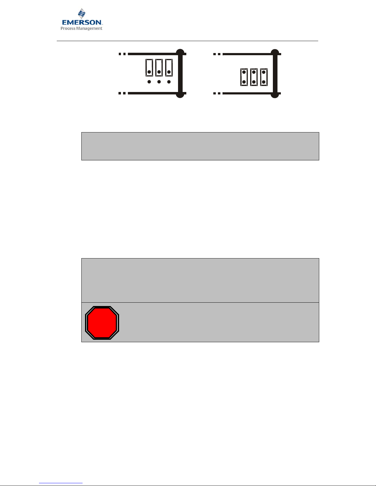
1.5.1 Jumper RS 485
RS 485 bus operation requires an electrical terminator on the first and last bus device.
This is done with plug−in jumpers, that are on the controller board. The figure shows the position
of the jumpers.
To activate the bus terminator and to place lines “A” and “B” on the references, plug the jumpers
as shown in Fig. b). Fig. a) shows the jumper position for deactivated bus termination and open
references (delivery status).
• Plug−in jumper 1−2 closed: Bus line “B” via pull−down resistor on ground
• Plug−in jumper 3−4 closed: 120 Ω resistor between “A” and “B”
• Plug−in jumper 5−6 closed: Bus line “A” via pull−up resistor on +5 V
Page 11
Page 11
Product Information / Produktinformation
A6151
Shaft Vibration Monitor
1
35
2
46
1
35
2
46
a)
b)
i
For trouble−free operation of the RS 485 bus, the lines “A” and “B” must be
connected on their references (+5 V, ground) in one monitor. This is only
possible if the bus termination jumper at this monitor has been closed as well.
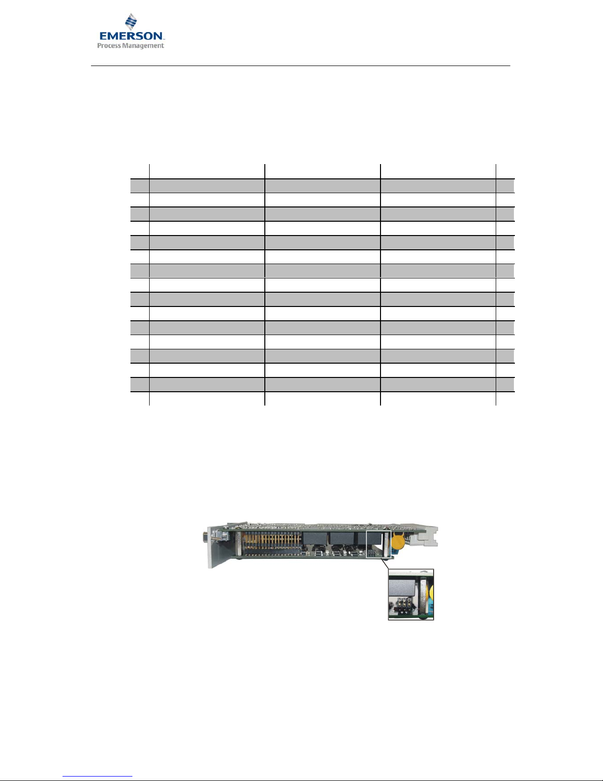
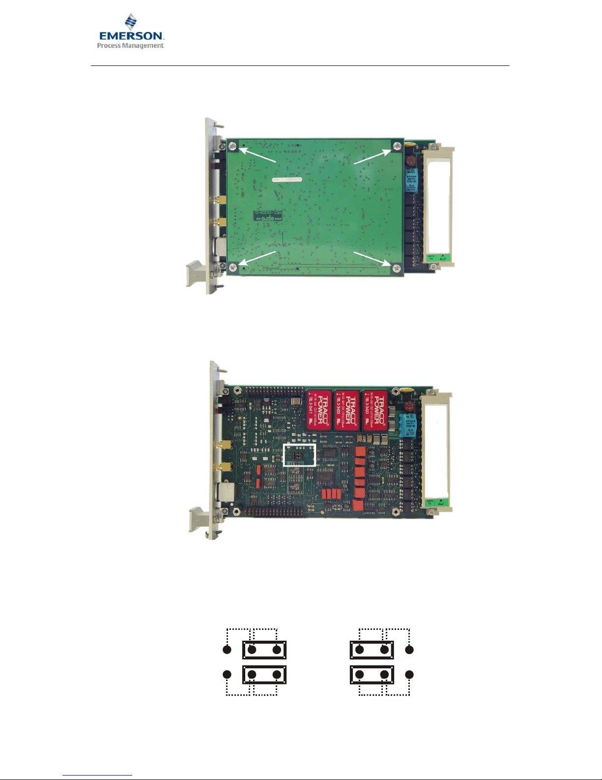
1.5.2 Sensor raw signal
The raw sensor signal (unfiltered, in−phase output signal of the converter with AC and DC
portion) is applied to the front panel SMB sockets and can be fed to the terminals z14: channel
1 and z16: channel 2 of the connection strip with the jumpers J2. As delivered, the J2 jumpers
are set, that on terminals z14 and z16 the dynamic portion of the sensor signal (scaled to output
range 0 ... 20 Vss) is applied. The controller board must be removed in order to switch the signal
on the connection strip. The following points describe the procedure:
i
The reference point for the raw sensor signal from channel 1 is the connection
strip terminal z6: Supply1(+), and for the raw sensor signal from channel 2 the
terminal d6: Supply2(+). If these terminals are connected with terminal b10,
then the reference point is connected to system ground (GND). In this case
the terninals b22: GND and b24: GND can be used as reference point.
STOP
When working at the monitor, ensure that there is adequate protection against
electrostatic discharge. For example, wear an ESD bracelet to prevent
electrostatic discharge via the monitor electronics.
Page 12
Page 12
Product Information / Produktinformation
A6151
Shaft Vibration Monitor
3. Use a cross head screwdriver to remove the four cross−headed screws, identified with the
arrows, in the following figure.
4. Carefully pull the controller board off the main board without tilting it. The position of the J2
jumpers on the main bard is identified with a white frame in the following figure.
5. To switch the raw sensor signal to terminals z14 and z16 place the jumpers as shown in b).
If the jumpers are set as shown in a) then the dynamic portion of the sensor signal is applied
on terminals z14 and z16.
J2
z14:
z16:
AC1
AC2
SENS1
SENS2
J2
z14:
z16:
AC1
AC2
SENS1
SENS2
a)
b)
Page 13

Page 13
Product Information / Produktinformation
A6151
Shaft Vibration Monitor
6. Place the controller board back on the main board and secure it with the four screws. Now,
the raw sensor signal is on the connection strip.
1.5.3 Installation
1. Check the slot wiring prior to installing the monitor.
2. Push the A6151 monitor into the prepared slot and press it with light pressure into the plug
connector.
3. Hand tighten the two anchoring screws on the front panel to secure the monitor.
Any other information, e. g. shielding and grounding, configuration of the monitor, etc., can be
found in the direction for use of the A6110, order number: 6110−90001.
1.6 Technical Data
Only information with tolerances and limit values are considered as binding data. Data without
tolerances or error limits are provided as information only. We reserve the right to make technical
changes − particularly to the software.
All of the following information applies uniformly for channel 1 and channel 2, if not otherwise
specified.
1.6.1 Signal conditioning
Two separate signal inputs for channel 1 and channel 2 with uncoupled signal conditioning.
Measured value inputs
Differential voltage amplification inputs, non−reactive, open−circuit and short−circuit proof.
Channel 1 z8: AIN1 (−); z10: AIN1 (+)
Channel 2 d8: AIN2 (−); d10: AIN2 (+)
Input nominal range −1,0 ... −22.16 V
Limit range 0 ... −30 V DC
Input resistance > 100 kΩ
Page 14

Page 14
Product Information / Produktinformation
A6151
Shaft Vibration Monitor
Signal conditioning
Sensor signal outputs Front sockets SMB and/or z14 / z16*, uncoupled,
open circuit and short circuit proof, non reactive.
Channel 1 − SENS 1 SMB K1
Channel 2 − SENS 2 SMB K2
Signal output −1 ... −24 V; signal 1:1 to sensor input signal
Precision ±1
% of f.s.d.
Frequency range 0.2 ... 200 Hz (−3 dB) ±20 %
Per. load resistance > 100 kΩ
Internal resistance 1 kΩ
*Depends on the jumper setting J2.
Dynamic outputs
The AC portion of the sensor signal is output as scaled value.
Channel 1 − AC1 / Channel 2 − AC2 z14 / z16* open−circuit and short−circuit proof, non−
reactive
Nominal range 0...20 Vpp
Measuring range Corresponds to the measuring range configured for
the characteristic value, min. 400 mVpp,
max. 8000 mVpp
Precision
±1
% of f.s.d.
Frequency range 0.2 Hz ... 200 Hz (−3 dB) ±20 %
Per. load resistance > 10 kΩ
Source impedance 10 kΩ
Internal resistance Approximately 20 Ω
*Depends on the jumper setting J2.
Scaled d.c. Outputs
The DC portion of the sensor signal (proportional to the static distance sensor / measurement
object) is output as standardized DC voltage NGL.
Channel 1 − NGL1 / channel 2 − NGL2 z12 / d12 open circuit and short circuit proof, non
reactive
Nominal range 0 ... +10 V DC
Measuring range According to the configured operating range of the
sensor
0 V corresponds to the lower value of the work range
+10 V corresponds to the upper value of the work
range
Precision / resolution
±1
% of f.s.d. / 12 Bit
Per. load resistance > 10 kΩ
Internal resistance Approximately 50 Ω
Page 15

Page 15
Product Information / Produktinformation
A6151
Shaft Vibration Monitor
Signal conditioning for characteristic values
The input signals are conditioned by adjusting amplifier, range−dependent amplifier, high
pass, and low pass prior to digitalization.
Range setting Is determined in the configuration
Minimum measuring range 400 mVpp
Maximum measuring range
8000 mVpp
Frequency range
High pass filter Butterworth filter 2nd order
− Parameters can be set 0.2 Hz (−3 dB)
0.7 Hz (−3 dB)
− Tolerance ±20 %
Low pass filter
Butterworth filter 5nd order
Parameter range 10 Hz ... 200 Hz in 0.01 Hz
increments
Characteristic value formation Depends on the configuration
2−channel operation S1 and S2 separated characteristic values, optionally
in 0−P or P−P evaluation.
Maximum deflection S
max
S
max
= max sk (t);
sk(t) + s
1
(t)2) s2(t)
2
Ǹ
Maximum vibration amplitude S
ppm
S
ppm
= Max (s
p−p
1 or s
p−p
2 )
Current outputs−characteristic values
Characteristic value formation and evaluation depends on the functions specified in the
configuration.
Current output 1 − I1+ / I1− z18 / b18 (0 V / common)
Current output 2 − I2+ / I2− z20 / b20 (0 V / common)
Nominal range 0 ... 20 mA or 4 ... 20 mA, depending on the
configuration
−Life zero operation in 4 ... 20 mA operation you can specify via the
configuration that the output is set to 0 mA if a fault is
detected.
Precision / resolution ±1 % of f.s.d. / 16 Bit
Per. load resistance 500 Ω
Page 16

Page 16
Product Information / Produktinformation
A6151
Shaft Vibration Monitor
Signal outputs EO 1 / EO 2
d14 / d16
voltage output 0 ... 10V. For modes with separate channels according to the characteristic
value. For modes S
max
and S
PPmax
outputs of the single−channel measured values.
Measuring range and evaluation according to the characteristic value.
Depending on the application and configuration the outputs EO can be used for linkage or for
display.
Open circuit and short circuit proof, non reactive.
Nominal range 0 ... +10 V DC
Resolution 8−bit
Per. load resistance > 10 kΩ
Internal resistance Approximately 50 Ω
Signal inputs EI1 / EI2
Inputs for single−channel measurement values 0 ... +10 V for connection with EO outputs.
Voltage input EI1 / EI2 b14 / b16
Nominal voltage range 0 ... +10 V DC
Resolution 10−bit
Input resistance > 100 kΩ
Signal input KEY
The key pulse is required for internal RPM determination for checking the measurements in
the measured value analysis.
Signal input KEY (N) d22
Signal level 24 V logic,: LOW = 0 ... 3 V; HIGH = 13 ... 48 V
Input resistance > 10 kΩ
Page 17

Page 17
Product Information / Produktinformation
A6151
Shaft Vibration Monitor
1.6.2 Channel monitoring
Monitoring function Constant monitoring
Sensor signals GOOD range (configuration dependent)
GOOD thresholds
− Lower threshold value Sensor work range lower value −0.5 V
− Upper threshold value Sensor work range upper value +0.5 V
System voltages Voltage − OK
μP function (watchdog) WD − OK
Configuration & setting para−
meters
C&P − OK
External disable signal ES
Status channel monitoring
Channel status = no error (OK) if (voltage_OK = yes)
AND (WD_OK = yes)
AND (C&P_OK = yes)
AND (Sensor signal
in the GOOD range)
AND (Ext. disable = no)
Channel status = error If the previous condition is not satisfied
Channel status = release delayed When switching from error case to OK status or when
switching on the module a release delay of 15 s (±2 s)
is active
Visualization
Green LED on the front panel
Channel status = no error (OK) Continuous light
Channel status = error Dark
Channel status = release delayed Flashing light
Channel Clear outputs
Opto−decoupled collector/emitter segments
Channel Clear channel 1, C1C / C1E z26 (collector) / z28 (emitter)
Channel Clear channel 2, C2C / C2E z30 (collector) / z32 (emitter)
Ext. disabled or status = error or
release delayed
C−E disabled, max. perm. voltage: 48 V
Not ext. disabled and status = OK and
not release delayed
C−E conducting, max. perm. current: 100 mA
Page 18

Page 18
Product Information / Produktinformation
A6151
Shaft Vibration Monitor
Input external disable ES
z22 − for disabling the limit value alarms; e.g. for service work etc.
Disable function Input LOW = disable the channel monitoring and limit
value formation
Release Input HIGH or not switched = enable of channel
monitoring and limit value formation
Signal level LOW: 0 ... +3 V, HIGH: +13 ... +48 V
1.6.3 Limit value formation and alarms
Two alarm channels, each with an alarm output ALERT and DANGER, and separate limit value
adjustment. Alarming if the characteristic value exceeds the limit value parameters. (current
value > limit value)
Setting the limit value
By setting parameters, depending on the configuration for measurement operation, characteristic value formation, range etc.
Setting condition Limit value ALERT < limit value DANGER
Setting range 0 ... 100
% of the measuring range parameters
Resolution and reproducibility 1 % based on the measuring range end value
Hysteresis Configurable, 0 ... 20 % based on the measuring range
end value
The hysteresis is only effective with decreasing
current value
Alarm delay
Can be configured to 0 (off), 1,2,3,4,5 sec.; effective on the alarm outputs.
Alarm blocking
Blocking If (C&P active = yes) OR
(Voltage or watchdog not OK) OR
(Ext. disable = disable) OR
(Channel status = error and limit value
suppression on*) OR
(Channel status = release delayed) AND
Channel monitoring effect = yes
No blocking
If the above condition is not satisfied
* In the configuration it is specified whether the alarm outputs will be blocked by channel
monitoring.
Page 19

Page 19
Product Information / Produktinformation
A6151
Shaft Vibration Monitor
Alarm visualization
By red LEDs, each for channel 1 and channel 2
No limit value exceeded or alarm
blocked
LED off
ALERT, no DANGER LED flashes at 2 Hz (pulse/pause 1:1)
DANGER LED on continuously
Alarm outputs
Opto−decoupled collector/emitter segments
Alert channel 1 A1−C / A1−E b26 (collector) / b28 (emitter)
Danger channel 1 D1−C / D1−E d26 (collector) / d28 (emitter)
Alert channel 2 A2−C / A2−E b30 (collector) / b32 (emitter)
Danger channel 2 D2−C / D2−E d30 (collector) / d32 (emitter)
Maximum value for alarm outputs C−E disabled: max. perm. U
CE
: 48 V
C−E conductive: max. perm. U
CE
: 100 mA
Alarm status of the alarm outputs Conducting in open circuit mode, disabled in
closed−circuit mode
Open circuit mode / closed−circuit mode
The digital inputs SC−A and SC−D can be selected with external signals.
Switchover ALERT
d24 − SC−A = HIGH / blank
= open circuit mode
d24 − SC−A = LOW = closed−circuit mode
Switchover DANGER z24 − SC−D = HIGH / blank
= open circuit mode
z24 − SC−D = LOW = closed−circuit mode
Switch level LOW = 0 ... +3 V
HIGH = 13 ... 48 V
Input resistance > 10 kΩ
1.6.4 Communication interfaces
Interface RS 232
Front socket for connecting a laptop / computer for configuration and visualization purposes
Round plug connector on the front
side
Mini DIN socket type TM 0508A/6 for parameterization
cable (included in the operating kit)
Page 20

Page 20
Product Information / Produktinformation
A6151
Shaft Vibration Monitor
Interface RS 485
d4, z4 bus interface for communication with an MMS 68xx epro Interface card and the
configuration software.
1.6.5 Power supply
The monitor system voltages, and thus the 0 V / common connections for the measurement
and monitoring inputs and outputs, are galvanically separated.
Supply voltage inputs Two redundant diode decoupled inputs for nominal
+24 V with common 0 V reference
Voltage input UB+ / UN+ d2 / z2
Common reference 0 V U− b2
Perm. voltage range 19 ... 31.2Vdc (IEC 654−2 class DC 4)
CSA: 24Vdc; SELV LPS
Power consumption max. 6 W, at 24 V max. 250 mA
Monitor system voltage
The system voltages required for the internal supply are constantly monitored. If undervoltage
is detected an error message is generated.
Sensor supply
For both channels of the monitor
Separation Decoupled and galvanically separated from the
supply voltage, can be operated in parallel with other
monitors, open circuit and short circuit proof, non
reactive.
Sensor supply channel 1 Supply1(−) / Supply1(+) b6/z6
Sensor supply channel 2 Supply2(−) / Supply2(+) b8/d6
supply voltage 26.75 V DC; Tolerance ±2
%
Residual ripple < 20 mVpp (at nominal current 20 mA)
Max. current 35 mA
Max. short−circuit current 0 mA ≤ I short−circuit ≤ 5 mA;
Open circuit and short−circuit proof
Page 21

Page 21
Product Information / Produktinformation
A6151
Shaft Vibration Monitor
1.6.6 Environmental conditions
Application class KTF in accordance with DIN 40040
Ambient temperature
Reference temperature +25 °C
Nominal use range 0...+45°C (CSA
requirement and recommended range)
max. range −10°C ... +65°C (not CSA conform)
Storage, transport temperature −30 ... +85 °C
Operating altitude up to 2000m above sea level
Relative humidity
≤ 95
% non condensing
Vibration In accordance with IEC−68 − 2 Part 6
Path 0.15 mm at 10 ... 55 Hz
Acceleration 19.6 mm/s
2
at 55 ... 150 Hz
Shock
In accordance with IEC-68 - 2 Part 29
Peak acceleration value 98 m/s
2
Nominal duration of shock 15 ms
Enclosure protection class IP 00, open design in accordance with DIN 40050
EMC immunity In accordance with EN 50 081−1 / EN 50 082−2
satisfied
Allowed degree of pollution Category 2 (According to IEC 61010−1)
Enviromental Area Indoor use only
1.6.7 Mechanical structure
PCB Euro format (100 mm x 160 mm) in accordance with
DIN 41494
Width 6 TE (approximately 30 mm)
Plug connector DIN 41612, form F 48 M
Front element
2 LEDs green Channel Clear channel 1 / 2
2 LEDs red Alarms channels 1 / 2
2 SMB socket connectors For sensor channel 1 / 2
1 mini DIN round socket connector RS 232 for connecting a laptop / computer
(for configuration and visualization purposes)
Weight Approximately 320 g without packaging,
approximately 450 g with standard packaging
Page 22

Seite 22
Product Information / Produktinformation
A6151
Wellenschwingungsmonitor
2
D
WELLENSCHWINGUNGSMONITOR
Der zweikanalige niederfrequenz Wellenschwingungsmonitor A6151 ist eine Baugruppe des
A6000 Maschinenüberwachungssystems. Der mikrocontrollergesteuerte Monitor dient in Ver-
bindung mit zwei Wirbelstrom−Messketten der Messung und Überwachung der relativen
Wellenschwingung an Wasserturbinen.
Die zwei Kanäle des Monitors können mittels der Konfiguration als getrennte Kanäle benutzt
oder miteinander verknüpft werden. Folgende Betriebsarten sind möglich:
• Der separate Zweikanalbetrieb.
• Die Berechnung und Ausgabe des Maximalwerts S
max
.
• Die Berechnung und Ausgabe der größeren Schwingbreite S
ssmax.
Die Kenngrößen können je Kanal über einen Stromausgang 0/4 ... 20 mA ausgegeben werden.
i
In dieser Produktinformation wird die Montage und der elektrische Anschluss
des Monitors beschrieben. Die Konfiguration des A6151 ist ähnlich der Konfiguration des A6110. Daher können zusätzliche Informationen bezüglich
Konfiguration und Installation der Gebrauchsanleitung des A6110 (Bestellnummer: 6100−90001) entnommen werden. Diese Gebrauchsanleitung ist
bestandteil der Konfigurationssoftware CD. Unterschiede in Installation und
Konfiguration werden in dieser Produktinformation beschrieben.
Um den sicheren Betrieb des Monitors zu gewährleisten und um alle
Funktionen des Gerätes einstellen zu können ist es erforderlich, die jeweils
aktuellsten Versionen von Konfigurationssoftware (ab Version 2.07 Beta 78)
und Gebrauchsanleitung zu verwenden.
Die Verwendung älterer Konfigurationsprogramme oder Gebrauchs−
anleitungen kann Funktionseinschränkungen oder Fehlfunktionen zur Folge
haben.
2.1 Lieferumfang
Folgende Teile gehören zum Lieferumfang und müssen in der Sendung enthalten sein:
• Wellenschwingungsmonitor A6151
• diese Produktinformation
Zubehör (nicht im Lieferumfang enthalten):
• MMS ParaKit (Best.−Nr. 9510−00027)
Sollte der Inhalt unvollständig sein oder irgend welche Defekte vorliegen, so muss dies beim
Überbringer sofort reklamiert werden. Außerdem muss die zuständige epro Verkaufsstelle
verständigt werden, um Reparatur oder Ersatz des Gerätes zu ermöglichen. Eventuell
erforderliche Reparaturen oder Kalibrierung von A6000 Monitoren sind nur im epro−Werk
möglich.
Page 23

Seite 23
Product Information / Produktinformation
A6151
Wellenschwingungsmonitor
2.2 CSA Zertifizierung
STOP
Zur gültigen CSA Zertifizierung müssen alle Geräte (IMR 6000/xx und A6000)
mit einem entsprechenden CSA Label versehen worden sein.
Für den Fall das kein CSA Label auf dem Gerät angebracht wurde ist dieses
Gerät nicht CSA zugelassen!
Das entspechende CSA Label sieht wie nachfolgend dargestellt aus.
2.3 CSA − Akzeptanzkriterien
Dieses Gerät muss mit Schutzkleinspannung SELV LPS (C22.2 60950−1) 24V betrieben
werden. Diese Betriebsspannung muss von einem seperaten Speisegerät bezogen werden.
Das System sollte in einem zweckmäßigen Feuerschutzgehäuse installiert werden.
Das System ist bewertet für einen Umgebungstemperaturbereich von 0°C bis 45°C.
Es muss angemessener Zirkulationsfreiraum vorgesehen werden damit sich keine Hitze
aufstauen kann. Der Zirkulationsfreiraum muss mindestens 1 HE (1
3/4
inch) in allen Richtungen
betragen. Für den Fall das die Umgebungstemperatur des Racks über 45°C steigt müssen die
gerätschaften mit einem festen Lüfter, einer Kühlvorrichtung etc. auf den entsprechend
zugelassenen Temperaturbereich heruntergekühlt werden.
Werden mehrere 19” Rahmen übereinander in einem Schaltschrank installiert so sollten
anstelle des Zirkulationsfreiraum entsprechende 1HE Lüftereinschübe installiert werden. Da die
notwendigen Spezifikationen derartiger Lüfter aus den Umgebungs− und Standortbedingungen
des Schaltschrankes resultieren können keine generellen Lüfterspezifikationen festgelegt
werden.
Page 24

Seite 24
Product Information / Produktinformation
A6151
Wellenschwingungsmonitor
2.4 Hinweis zur Installation
STOP
Gemäß der IEC 61010 Richtlinie müssen fest installierte Systeme mit einer
Trenneinrichtung (ggf. einem Schalter und/ oder einem Leitungsschutz−
schalter nach IEC60947−1 und IEC60947−3) zum unterbrechen der
Spannungsversorgung ausgestattet sein. Bei Verwendung eines IMR
Systems kann dies, unter Beachtung dieser Richtlinie, durch einen Schalter
oder Leistungsschalter erfolgen.
Dazu muss sich dieser in der Gebäude− bzw. Schaltschrankinstallation
befinden, in unmittelbarer Nähe zum System implementiert sein und für den
Anwender leicht zugänglich sein.
Des weiteren muss jede derartige Trenneinrichtung entsprechend dem
zugehörigen System gekennzeichnet bzw. beschriftet sein.
2.5 Installation und Montage
Für die Montage des A6151 Monitors wird ein vorbereiteter Steckplatz in einem 19“
Baugruppenträger mit 3 HE oder einem anderen Intermas−kompatiblem Gehäuse benötigt. Der
Steckplatz muss mit einem 48−poligen Steckverbinder (DIN 41612, Bauform F 48 M)
ausgestattet sein. Die Pin−Belegung ist in der nachfolgenden Tabelle aufgeführt.
d
b z
2
UN+ (+ 24V) U− (0V/Common) UB+ (+24V, redundant)
2
4
A (RS 485) GND (BP, Common, RS 485) B (RS 485)
4
6
Supply2+ (sensor) Supply1− (sensor) Supply1+ (sensor)
6
8
AIN2− (Input) Supply2− (sensor) AIN1− (Input)
8
10
AIN2+ (Input) GND AIN1+ (Input)
10
12
NGL2 (scaled dc−output) GND NGL1 (scaled dc−output)
12
14
EO1 (voltage output1) EI1 (voltage input1) AC1 (sensor raw signal1)
14
16
EO2 (voltage output2) EI2 (voltage input2) AC2 (sensor raw signal2)
16
18
GWM (limit value) I1− (current output common) I1+ (current output CH1)
18
20
NC I2− (current output common) I2+ (current output CH2)
20
22
KEY−N (key signal input) GND ES (external lock)
22
24
SC−A (oper. principle alert) GND SC−D (oper. principle danger)
24
26
D1−C (danger1 collector) A1−C (alert1 collector) CC1−C (ch. clear1 collector)
26
28
D1−E (danger1 emitter) A1−E (alert1 emitter) CC1−E (ch. clear1 emitter)
28
30
D2−C (danger2 collector) A2−C (alert2 collector) CC2−C (ch. clear2 collector)
30
32
D2−E (danger2 emitter) A2−E (alert2 emitter) CC2−E (ch. clear2 emitter)
32
Jumper für RS 485
Der Betrieb des RS 485 Busses erfordert einen elektrischen Abschluss jeweils am ersten und
letzten Gerät des Busses.
Page 25

Seite 25
Product Information / Produktinformation
A6151
Wellenschwingungsmonitor
Dies geschieht mit Steckbrücken, die sich auf dem Kontrollerboard befinden. Das Bild zeigt die
Position der Jumper.
Um den Bus−Abschluss zu aktivieren und die Leitungen “A” und “B” auf die Bezüge zu legen,
stecken Sie die Jumper wie in Bild b) gezeigt. Das Bild a) zeigt die Jumperposition für einen deaktivierten Bus−Abschluss und offene Bezüge (Auslieferungszustand).
• Steckbrücke 1−2 geschlossen: Busleitung “B” über Pull−down Widerstand an Masse
• Steckbrücke 3−4 geschlossen: 120 Ω Widerstand zwischen “A” und “B”
• Steckbrücke 5−6 geschlossen: Busleitung “A” über Pull−up Widerstand an +5 V
1
35
2
46
1
35
2
46
a)
b)
i
Für einen störungsfreien Betrieb des RS 485 Busses müssen die Leitungen
“A” und “B” in einem Monitor auf ihre Bezüge (+5 V; Masse) gelegt werden,
dies ist nur möglich wenn in diesem Monitor auch der Busabschluss−Jumper
gesetzt ist.
Sensorrohsignal
Das, an den SMB−Buchsen der Frontplatte anliegende Sensorrohsignal (ungefilterte phasenrichtige Ausgangssignal des Konverters mit AC und DC Anteil) kann mit den Jumpern J2 auf die
Klemmen z14: Kanal 1 und z16: Kanal 2 der Steckleiste umgeschaltet werden. Hierfür muss das
Kontrollerboard entfernt werden. Die folgenden Punkte beschreiben die Vorgehensweise:
i
Der Bezugspunkt für das Sensorrohsignal von Kanal 1 ist die Steckleistenklemme z6: Supply1(+) und für das Sensorrohsignal von Kanal 2 die Klemme
d6: Supply2(+). Sind diese Klemmen mit der Klemme b10 verbunden, liegt
der Bezugspunkt auf Systemmasse (GND). In diesem Fall können auch die
Klemmen b22: GND und b24: GND als Bezugspunkt verwendet werden.
STOP
Achten Sie bei Arbeiten am Monitor auf ausreichenden Schutz vor elektrostatischen Entladungen. Tragen Sie z.B. ein ESD−Armband, um elektrostatische
Entladungen über die Monitorelektronik zu verhindern.
Page 26

Seite 26
Product Information / Produktinformation
A6151
Wellenschwingungsmonitor
1. Lösen Sie mit einem Kreuzschraubendreher die vier, im folgenden Bild mit den Pfeilen
gekennzeichneten Kreuzschrauben.
2. Ziehen Sie das Kontrollerboard vorsichtig, ohne zu verkanten von dem Mainboard ab. Die
Position der Jumper J2 auf dem Mainboard sind im folgenden Bild mit einem weißen
Rahmen gekennzeichnet.
3. Um das Sensorrohsignal auf die Klemmen z14 und z16 zu schalten, stecken Sie die Jumper
wie in b) dargestellt. Sind die Jumper wie in a) gesetzt, liegt an den Klemmen z14 und z16
der dynamische Anteil des Sensorsignals.
Page 27

Seite 27
Product Information / Produktinformation
A6151
Wellenschwingungsmonitor
J2
z14:
z16:
AC1
AC2
SENS1
SENS2
J2
z14:
z16:
AC1
AC2
SENS1
SENS2
a)
b)
4. Stecken Sie das Kontrollerboard wieder auf das Mainboard und sichern Sie es mit den vier
Schrauben. Das Sensorrohsignal liegt nun auf der Steckleiste.
Monitor−Einbau
1. Überprüfen Sie vor Einbau des Monitors die Steckplatzverdrahtung.
2. Schieben Sie den A6151 Monitor in den vorbereiteten Steckplatz und drücken Sie ihn mit
leichtem Druck in den Steckverbinder.
3. Zur Sicherung des Monitors schrauben Sie die beiden Befestigungsschrauben auf der
Frontplatte leicht handfest an.
Alle weiteren Informationen, wie z. B. Schirmung und Erdung, Konfiguration des Monitors, usw.,
finden Sie in der Gebrauchsanleitung “Wellenschwingungsmonitor A6151”, Bestellnr.
6100−90001.
2.6 Technische Daten
Nur Angaben mit Toleranzen oder Grenzwerten sind verbindliche Daten. Daten ohne
Toleranzen bzw. ohne Fehlergrenzen sind informative Daten. Technische Änderungen − vor
allem der Software − bleiben vorbehalten.
Alle folgenden Angaben gelten, sofern nicht anders angeben, für Kanal 1 und Kanal 2
gleichermaßen.
2.6.1 Signalkonditionierung
Zwei separate Signaleingänge für Kanal 1 und Kanal 2 mit voneinander entkoppelter Signalkonditionierung.
Messwerteingänge
Differenzspannungsverstärkereingänge, rückwirkungsfrei, leerlauf− und kurzschlussfest.
Kanal 1 z8: AIN1 (−); z10: AIN1 (+)
Kanal 2 d8: AIN2 (−); d10: AIN2 (+)
Eingangsnennbereich −1,0 ... −22,16 V
Grenzbereich 0 ... −30 V DC
Eingangswiderstand > 100 kΩ
Page 28

Seite 28
Product Information / Produktinformation
A6151
Wellenschwingungsmonitor
Signalkonditionierung
Sensorsignalausgänge Frontbuchsen SMB und/oder z14 / z16* entkoppelt,
leerlauf− und kurzschlussfest, rückwirkungsfrei
Kanal 1 − SENS 1 SMB K1
Kanal 2 − SENS 2 SMB K2
Signalausgang −1 ... −24 V; Signal 1:1 zum Sensoreingangssignal
Genauigkeit ±1 % vom Endwert
Frequenzbereich 0.2 ... 200 Hz (−3 dB) ±20 %
Zul. Belastungswiderstand >100 kΩ
Innenwiderstand 1 kΩ
*Abhängig von der Jumperstellung J2.
Dynamische Ausgänge
Der AC−Anteil des Sensorsignal wird als normierter Wert ausgegeben.
Kanal 1 − AC1 / Kanal 2 − AC2 z14 / z16* leerlauf− und kurzschlussfest,
rückwirkungsfrei
Nennbereich 0 ... 20 V ss
Messbereich entsprechend dem für die Kenngröße konfigurierten
Messbereich, min. 400 mVss, max. 8000 mVss
Genauigkeit ±1 % vom Messbereichsendwert
Frequenzbereich 0,2 Hz ... 200 Hz (−3 dB), ±20 %
Zul. Belastungswiderstand >10 kΩ
Innenwiderstand ca. 20 Ω
*Abhängig von der Jumperstellung J2.
Normierte Gleichwertausgänge
Der DC−Anteil des Sensorsignal (proportional dem statischen Abstand
Aufnehmer / Messobjekt) wird als normierte Gleichspannung NGL ausgegeben.
Kanal 1 − NGL1 / Kanal 2 − NGL2 z12 / d12 leerlauf− und kurzschlussfest,
rückwirkungsfrei
Nennbereich 0 ... +10 V DC
Messbereich entsprechend dem konfigurierten Arbeitsbereich des
Sensors, 0 V entspricht dem unteren Wert des
Arbeitsbereichs +10 V entspricht dem oberen Wert
des Arbeitsbereichs
Genauigkeit / Auflösung ±1 % vom Messbereichsendwert / 12 Bit
Zul. Belastungswiderstand >10 kΩ
Innenwiderstand ca. 50 Ω
Page 29

Seite 29
Product Information / Produktinformation
A6151
Wellenschwingungsmonitor
Signalkonditionierung für Kenngröße
Die Eingangssignale werden vor der Digitalisierung konditioniert durch Anpassverstärker,
bereichsabhängigem Verstärker, Hochpass und Tiefpass.
Bereichseinstellung wird bei der Konfiguration bestimmt
minimaler Messbereich 400 mV ss
maximaler Messbereich 8000 mV ss
Frequenzbereich
Hochpass 2 pol. Butterworth−Charakteristik
− parametrierbar 0,2 Hz (−3 dB)
0,7 Hz (−3 dB)
− Toleranz ±20 %
Tiefpass 5 pol. Butterworth−Charakteristik
Parametrierbereich 10 Hz ... 200 Hz
in 0,01 Hz−schritten
Kenngrößenbildung abhängig von der Konfiguration
2 Kanal−Betrieb S1 und S2 getrennte Kenngrößen, wahlweise in 0−S
oder S−S−Bewertung
Maximalausschlag S
max
nach
DIN 45670 Kenngröße A
S
max
= max sk (t);
sk(t) + s
1
(t)2) s2(t)
2
Ǹ
Größere Schwingbreite S
ppm
nach
DIN 45670 Kenngr. B bzw.
Max (X,Y) nach API 670
S
ppm
= (Sss1, Sss2) Max
S
ppm
= Max (s
s−s
1 oder s
s−s
2 )
Stromausgänge−Kenngröße
Die Kenngrößenbildung und Bewertung ist abhängig von den bei der Konfiguration
bestimmten Funktionen.
Stromausgang 1 − I1+ / I1− z18 / b18 (0 V / common)
Stromausgang 2 − I2+ / I2− z20 / b20 (0 V / common)
Nennbereich 0 ... 20 mA oder 4 ... 20 mA, abhängig von der
Konfiguration
− Life zero−Betrieb im 4 ... 20 mA Betrieb kann mittels der Konfiguration
bestimmt werden, dass der Ausgang bei Erkennung
einer Störung auf 0 mA gesetzt wird.
Genauigkeit / Auflösung ±1 % vom Messbereichsendwert / 16 Bit
Zul. Belastungswiderstand 500 Ω
Page 30

Seite 30
Product Information / Produktinformation
A6151
Wellenschwingungsmonitor
Signalausgänge EO 1 / EO 2
d14 / d16
Spannungsausgang 0 ... 10V. Bei Betriebsart mit separaten Kanälen entsprechend der
Kenngröße. Bei den Betriebsarten S
max
und S
ssmax
Ausgänge der Einzelkanalmesswerte.
Messbereich und Bewertung entsprechend der Kenngröße.
Abhängig von der Applikation und Konfiguration können die Ausgänge EO zur Verknüpfung
oder zur Anzeige verwendet werden.
leerlauf− und kurzschlussfest, rückwirkungsfrei.
Nennbereich 0 ... +10 V DC
Auflösung 8 Bit
Zul. Belastungswiderstand > 10 kΩ
Innenwiderstand ca. 50 Ω
Signaleingänge EI1 / EI2
Eingänge für Einzelkanalmesswerte 0 ... +10 V zur Verknüpfung mit EO−Ausgängen.
Spannungseingang EI1 / EI2 b14 / b16
Nennspannungsbereich 0 ... +10 V DC
Auflösung 10 Bit
Eingangswiderstand >100 kΩ
Signaleingang KEY
Der Key−Impuls wird zur internen Drehzahlbestimmung zur Steuerung der Messungen bei der
Messwertanalyse benötigt.
Signaleingang KEY (N) d22
Signalpegel 24 V Logik,: LOW = 0 ... 3 V; HIGH = 13 ... 48 V
Eingangswiderstand >10 kΩ
2.6.2 Kanalüberwachung
Überwachungsfunktion ständige Überwachung
Sensorsignale GUT−Bereich (konfigurationsabhängig)
GUT−Schwellen
− unterer Schwellwert Sensor−Arbeitsbereich unterer Wert −0,5 V
− oberer Schwellwert Sensor−Arbeitsbereich oberer Wert +0,5 V
Systemspannungen Spannung − OK
Page 31

Seite 31
Product Information / Produktinformation
A6151
Wellenschwingungsmonitor
μP Funktion (watchdog) WD − OK
Konfiguration & Parametrierung K&P − OK
externes Sperrsignal ES
Status Kanalüberwachung
Kanalstatus = kein Fehler (OK) wenn ( Spannung_OK = Ja )
UND (WD_OK = Ja)
UND (K&P_OK = Ja)
UND (Sensorsignal
im GUT−Bereich)
UND (Ext. Sperren = Nein)
Kanalstatus = Fehler falls die vorherige Bedingung nicht erfüllt ist
Kanalstatus = Freigabe verzögert bei Umschaltung vom Fehlerfall in den OK−Status
oder beim Einschalten des Moduls wird eine
Freigabeverzögerung von 15 s (±2 s) aktiv
Visualisierung
Grüne LED auf der Frontplatte
Kanalstatus = kein Fehler (OK) Dauerlicht
Kanalstatus = Fehler Dunkel
Kanalstatus = Freigabe verzögert Blinklicht
Ausgänge Channel Clear
Opto−entkoppelte Kollektor/Emitter−Strecken
Channel Clear Kanal 1, C1C / C1E
z26 (Kollektor) / z28 (Emitter)
Channel Clear Kanal 2, C2C / C2E z30 (Kollektor) / z32 (Emitter)
Ext. gesperrt oder Status = Fehler
oder Freigabe verzögert
C−E gesperrt, max. zul. Spannung: 48 V
nicht ext. gesperrt und Status = OK
und nicht Freigabe verzögert
C−E leitend, max. zul. Strom: 100 mA
Eingang extern Sperren ES
z22 − zum Sperren der Grenzwertalarme; z. B. bei Wartungsarbeiten etc.
Funktion Sperren Eingang LOW = Sperren der Kanalüberwachung und
Grenzwertbildung
Freigabe Eingang HIGH oder unbeschaltet = kein Sperren der
Kanalüberwachung und Grenzwertbildung
Signalpegel LOW: 0 ... +3 V, HIGH: +13 ... +48 V
Page 32

Seite 32
Product Information / Produktinformation
A6151
Wellenschwingungsmonitor
2.6.3 Grenzwertbildung und Alarme
Zwei Alarmkanäle mit je einem Alarmausgang ALERT und DANGER und separater
Grenzwerteinstellung. Alarmierung, wenn die Kenngröße den parametrierten Grenzwert
überschreitet. (Istwert > Grenzwert)
Grenzwerteinstellung
Durch Parametrierung, abhängig von der Konfiguration für Messbetrieb, Kenngrößenbildung,
Bereich etc.
Einstellbedingung Grenzwert ALERT < Grenzwert DANGER
Einstellbereich 0 ... 100 % des parametrierten Messbereiches
Auflösung und Reproduzierbarkeit 1 % bezogen auf den Messbereichsendwert
Hysterese Konfigurierbar, 0 ... 20 % bezogen auf den Messbe-
reichsendwert
Die Hysterese ist nur bei sinkendem Istwert wirksam.
Ansprechverzögerung
konfigurierbar auf 0 (aus),1,2,3,4,5 sek.; wirksam auf die Alarmausgänge.
Alarmblockierung
Blockierung wenn (K&P aktiv = ja)
ODER
(Spannung oder watchdog nicht ok) ODER
(Ext. Sperren = sperren) ODER
(Kanalstatus = Fehler und Grenzwert−
unterdrückung = an*)
ODER
(Kanalstatus = Freigabe verzögert) UND
Kanalüberwachungseinwirkung = Ja
Keine Blockierung Wenn obige Bedingung nicht erfüllt ist
* In der Konfiguration wird festgelegt, ob die Blockierung der Alarmausgänge durch die Kanalüberwachung erfolgen soll.
Alarmvisualisierung
Durch je ein rotes LED für Kanal 1 und 2
Keine Grenzwertüberschreitung oder
Alarme blockiert
LED Aus
Voralarm (ALERT), kein Hauptalarm LED blinkt mit 2 Hz (Puls/Pause 1:1)
Hauptalarm LED hat Dauerlicht
Page 33

Seite 33
Product Information / Produktinformation
A6151
Wellenschwingungsmonitor
Alarmausgänge
Opto−entkoppelte Kollektor / Emitter−Strecken
Voralarm Kanal 1 A1−C / A1−E b26 (Kollektor) / b28 (Emitter)
Hauptalarm Kanal 1 D1−C / D1−E d26 (Kollektor) / d28 (Emitter)
Voralarm Kanal 2 A2−C / A2−E b30 (Kollektor) / b32 (Emitter)
Hauptalarm Kanal 2 D2−C / D2−E d30 (Kollektor) / d32 (Emitter)
Maximalwerte für Alarmausgänge C−E gesperrt: max. zuläss. U
CE
: 48 V
C−E leitend: max. zuläss. I
CE
: 100 mA
Alarmzustand der Alarmausgänge leitend im Arbeitsstrombetrieb, gesperrt im Ruhe-
strombetrieb
Arbeitsstrom− / Ruhestrombetrieb
Durch externe Verdrehung der Digitaleingänge SC−A und SC−D wählbar.
Umschaltung ALERT d24 − SC−A = HIGH / unbeschaltet
= Arbeitsstrom
d24 − SC−A = LOW = Ruhestrombetrieb
Umschaltung DANGER z24 − SC−D = HIGH / unbeschaltet
= Arbeitsstrom
z24 − SC−D = LOW = Ruhestrombetrieb
Schaltpegel LOW = 0 ... +3 V
HIGH = 13 ... 48 V
Eingangswiderstand > 10 kΩ
2.6.4 Kommunikationsschnittstellen
Schnittstelle RS 232
Frontbuchse zum Anschluss eines Laptops / Rechners zwecks Konfiguration und
Visualisierung
Rundsteckverbinder auf Frontseite Mini−DIN−Buchse Typ TM 0508A/6 für Parametrier-
kabel (im Operating Kit enthalten)
Schnittstelle RS 485
d4, z4 Busschnittstelle für Kommunikation mit z. B. einer Interfacekarte MMS 68xx und der
Konfigurationssoftware.
Page 34

Seite 34
Product Information / Produktinformation
A6151
Wellenschwingungsmonitor
2.6.5 Spannungsversorgung
Die Monitorsystemspannungen und somit auch die 0 V / common−Anschlüsse für die Mess−
und Überwachungsein− und −ausgänge sind voneinander galvanisch getrennt.
Versorgungsspannungseingänge zwei redundante, diodenentkoppelte Eingänge für
nominal +24 V mit gemeinsamen 0 V Bezug
Spannungseingang UB+ / UN+ d2 / z2
Gemeinsamer Bezug, 0 V U− b2
Zul. Spannungsbereich 19 ... 31,2 Vdc (IEC 654−2 Klasse DC 4)
CSA: 24Vdc; SELV LPS
Leistungsaufnahme max. 6 W, bei 24 V max. 250 mA
Monitorsystemspannung
Die für die interne Versorgung benötigten Monitor−Systemspannungen werden ständig auf
Unterspannung überwacht. Bei Erkennung einer Unterspannung wird eine Fehlermeldung
generiert.
Sensorspeisung
Für beide Kanäle des Monitors
Trennung entkoppelt und zu den übrigen Systemspannungen
und zur Versorgungsspannung galvanisch getrennt,
mit anderen Monitoren parallel rückwirkungsfrei
betreibbar,
leerlauf− und kurzschlussfest.
Sensorspeisung Kanal 1 Supply1(−) / Supply1(+) b6/z6
Sensorspeisung Kanal 2 Supply2(−) / Supply2(+) b8/d6
Speisespannung 26,75 V DC; Toleranz ±2 %
Restwelligkeit < 20 mVss (bei Nennstrom 20 mA)
max. Strom 35 mA
max. Kurzschlussstrom 0 mA ≤ I kurzschl. ≤ 5 mA;
leerlauf− und kurzschlussfest
Page 35

Seite 35
Product Information / Produktinformation
A6151
Wellenschwingungsmonitor
2.6.6 Umgebungsbedingungen
Anwendungsklasse KTF nach DIN 40040
Umgebungstemperatur
Bezugstemperatur +25°C
Nenngebrauchsbereich 0...+45°C (CSA
Anforderung und empfohlener Bereich)
max. Bereich −10°C ... +65°C (nicht CSA konform)
Lagerungs−, Transporttemperatur −30 ... +85°C
Betriebshöhe bis zu 2000m über NN
Relative Feuchte
≤ 95 % ohne Betauung
Schwingung nach IEC−68 − 2 Teil 6
Weg 0,15 mm bei 10 ... 55 Hz
Beschleunigung 19,6 mm/s
2
bei 55 ... 150 Hz
Schock nach IEC−68 − 2 Teil 29
Beschleunigungsspitzenwert 98 m/s
2
Nominelle Schockdauer 16 ms
Gehäuseschutzart IP 00, offene Bauweise nach DIN 40050
EMV−Festigkeit nach EN 50 081−1 / EN 50 082−2 erfüllt
Zulässiger Verschmutzungsgrad Kategorie 2 (nach IEC 61010−1)
Betriebsumgebung Gebrauch ausschließlich in geschlossenen Räumen
2.6.7 Mechanischer Aufbau
Leiterplatte Euro−Format (100 mm x 160 mm) nach DIN 41494
Breite 6 TE (ca. 30 mm)
Steckverbinder DIN 41612, Bauform F 48 M
Frontelemente
2 LEDs Grün Channel Clear Kanal 1 / 2
2 LEDs Rot Alarme Kanal 1 / 2
2 SMB Steckbuchse für Sensorsignal Kanal 1 / 2
1 Mini−DIN Rundsteckbuchse für RS 232 zum Anschluss eines Laptops / Rechners
(zwecks Konfiguration und Parametrierung)
Gewicht ca. 320 g (ohne Verpackung)
ca. 450 g mit Standardverpackung
Page 36

Page/Seite 36
Product Information / Produktinformation
A6151
Connection Diagrams and Figures / Anschlusspläne und Abbildungen
3 CONNECTION DIAGRAMS AND FIGURES /
ANSCHLUSSPLÄNE UND ABBILDUNGEN
Supply1+
Supply1−
Supply2+
Supply2−
AIN1+
AIN1−
AIN2−
AIN2+
GND
UN+
U−
UB+
ES
GWM
don‘t use
SC−A
AC1
signal 1
sensor raw
SC−D
GND
GND
KEY
signal 2
sensor raw
EI2
EI1
EO2
EO1
AC2
RS485−B
A2−C
RS485−A
CC1−C
CC1−E
CC2−C
CC2−E
D1−C
D1−E
A1−E
A1−C
D2−C
D2−E
A2−E
RS232
I1+
GND
GND
GND
front socket
I1−
I2+
I2−
NGL1
NGL2
b24
Block diagram / Blockschaltbild A6151
Page 37

Page/Seite 37
Product Information / Produktinformation
A6151
Connection Diagrams and Figures / Anschlusspläne und Abbildungen
AIN1−
AIN1+
Supply1−
Supply1+
AIN2−
AIN2+
Supply2−
Supply2+
GND
GND
Alert1
Danger1
Alert2
Danger2
Channel
Clear1
Channel
Clear2
EI1
EI2
FX
ES
KEY (N)
UN+
U−
UB+
A
B
BP
NGL1
GND
NGL2
EO1
EO2
AC1
GND
AC2
I1+
SC−D
SC−A
I2−
I2+
I1−
AC−C
A1−E
D1−C
D1−E
A2−C
A2−E
D2−C
D2−E
C1−C
C1−E
C2−D
C2−E
Shaft vibration
Monitor
A6151
OUT
−24V
CON0xx
PR642x
OUT
−24V
CON0xx
PR642x
measuring
ground
protective
ground
0 ... +10V
protective ground
to
Cabinet
Field
Factor x
Alarm stop
ext. lock
KEY
0 ... +10V
b14
b18
z22
d18
d22
z8
z10
z6
b6
d10
d6
b8
b22
b10
d8
d4
z4
b4
z12
b12
d12
d14
d16
z14
b24
z16
z18
b18
z20
b20
d24
z24
b26
b28
d26
d28
b30
b32
d30
d32
z26
z28
z30
z32
RS485 BUS
nominal dc output channel 1
voltage output CH1
voltage output CH2
sensor raw signal CH1 (Jumper J2)
sensor raw signal CH2 (Jumper J2)
current output CH1
current output CH2
alert:
danger:
0 ... +10V
0 ... +10V
0 ... +10V
0 ... +10V
0/4 ... +20mA
0/4 ... +20mA
0V 0V
−24V /1
0V (24V)
−24V /2
b2
z2
d2
nominal dc output channel 2
closed−/ open circuit current
closed−/ open circuit current
Connection diagram / Anschlussdiagramm
Page 38

Page/Seite 38
Product Information / Produktinformation
A6151
Connection Diagrams and Figures / Anschlusspläne und Abbildungen
2
6
4
8
10
12
14
16
18
20
22
24
26
28
30
32
2
6
4
8
10
12
14
16
18
20
22
24
26
28
30
32
db z
d
b
UB+ (+24V)
U− (0V/Common)
UN+ (+24V, redundant)
Supply2+ (sensor)
Supply1− (sensor)
Supply1+ (sensor)
AIN2− (input)
Supply2− (sensor)
AIN1− (input)
AIN2+ (input)
C Screen / Common
AIN1+ (input)
A (RS485) Common
B (RS485)
NGL2 (scaled dc output) GND Common
NGL1 (scaled dc output)
EO1 (voltage output1)
EI1 (voltage input1)
AC1 (sensor raw signal)*
EO2 (voltage output2) EL2 (voltage input2)
AC2 (sensor raw signal)*
GWM (limit value) I1−(current output common)
I1+ (current output CH1)
NC I2−(current output common)
I2+ (current output CH2)
KEY (N) (key signal input)
GND ES (external lock)
SC−A (oper. principle alert)
GND
SC−D (oper.principle danger)
D1−C (danger1 collector)
D2−C (danger2 collector)
A1−C (alert collector)
A2−C (alert2 collector)
C1−C (chan. clear1 collector)
C2−C (chan.clear2 collector)
D1−E (danger1 emitter)
D2−E (danger2 emitter)
A1−E (alert1 emitter)
A2−E (alert2 emitter)
C1−E (chan.clear1 emitter)
C2−E (chan.clear2 emitter)
z
*Only if Jumper J2 is closed. / Nur wenn Jumper J2 gesetzt ist.
Pin allocation / Steckerbelegung
Page 39

Page/Seite 39
Product Information / Produktinformation
A6151
Connection Diagrams and Figures / Anschlusspläne und Abbildungen
All dimensions in mm
Alle Abmessungen in mm
30.1
6 TE/HP
128.4
3 HE/RU
2.5
17
173.5
1
0
0
160
27
2.5
Dimensions A6151
Abmessungen A6151
Page 40

Page/Seite 40
Product Information / Produktinformation
A6151
PI Revision List
4 PI REVISION LIST
Version Date Changes Chapter
1.000 15.08.2011 Initial Version
1.001 21.09.2011 Translation corrections all
1.002 26.02.2013 Change of service address Europe
Page 41

EG-Konformitätserklärung
EC-Declaration of Conformity
Wir (We): epro GmbH, Jöbkesweg 3, 48599 Gronau
erklären in alleiniger Verantwortung, dass das Produkt:
declare under the exclusive liability that the product:
Produktbezeichnung (Product designation): System A6000
Produktbeschreibung (Product description): Modul zur Auswertung von dynamischen und
statischen Messwerten.
Module for evaluation of dynamic and static
measuring values
Artikelnummer (Product codes): 9199−00XXX
CEKennzeichnung entsprechend der EU− Richtlinie/ CE identification corresponds to EU directive:
98/336 / EWG (EMV) geändert/ modified 97/236 ; EWG 92/31 / EWG; 93/68 / EWG.
auf das sich diese Erklärung bezieht, mit der/den folgenden Norm(en) oder normativen Dokumenten übereinstimmt:
which is subject of this declaration, is in conformity with the following standards or normative
documents:
Bestimmungen der Richtlinie
Terms of the directive
Titel und/oder Nr.
Title and/or no.
Fachgrundnor m Störaussendung, Industriebereich
Engineering standard interference emission, industrial
applications
Fachgrundnorm Störfestigkeit, Industriebereich
Engineering standard interference immunity, industrial
applications
DIN EN 55011 + A1 + A2
DIN EN 61326 + A1 + A2 + A3
einschliesslich / including:
DIN EN 61000−4−2 + A1 + A2
DIN EN 61000−4−3 + A1
DIN EN 61000−4−4
DIN EN 61000−4−5 + A1
DIN EN 61000−4−6 + A1
Wir weisen darauf hin, dass
die Konformität und damit die Betriebserlaubnis erlischt, wenn dieses Erzeugnis ohne unsere
ausdrückliche Genehmigung geändert wird.
Nicht−Fachleute die Gegebenheiten des Einsatzgebietes und die daraus resultierenden
Anforderungen vor der Inbetriebnahme prüfen lassen sollen.
We point out that
the conformity and thus the approval for the operation lapses, if the product is modified without our
explicit permission (without consultation with us).
Non specialists should let check the conditions of the operational area and the requirements
resulting thereof before installation.
Gronau, 04.05.2011
Ort und Datum Geschäftsbereichsleiter Leiter Qualitätsmanagement
Place and date Divisional director Head of quality management
Certif_MMS_06_Rev_02
 Loading...