

Page 1
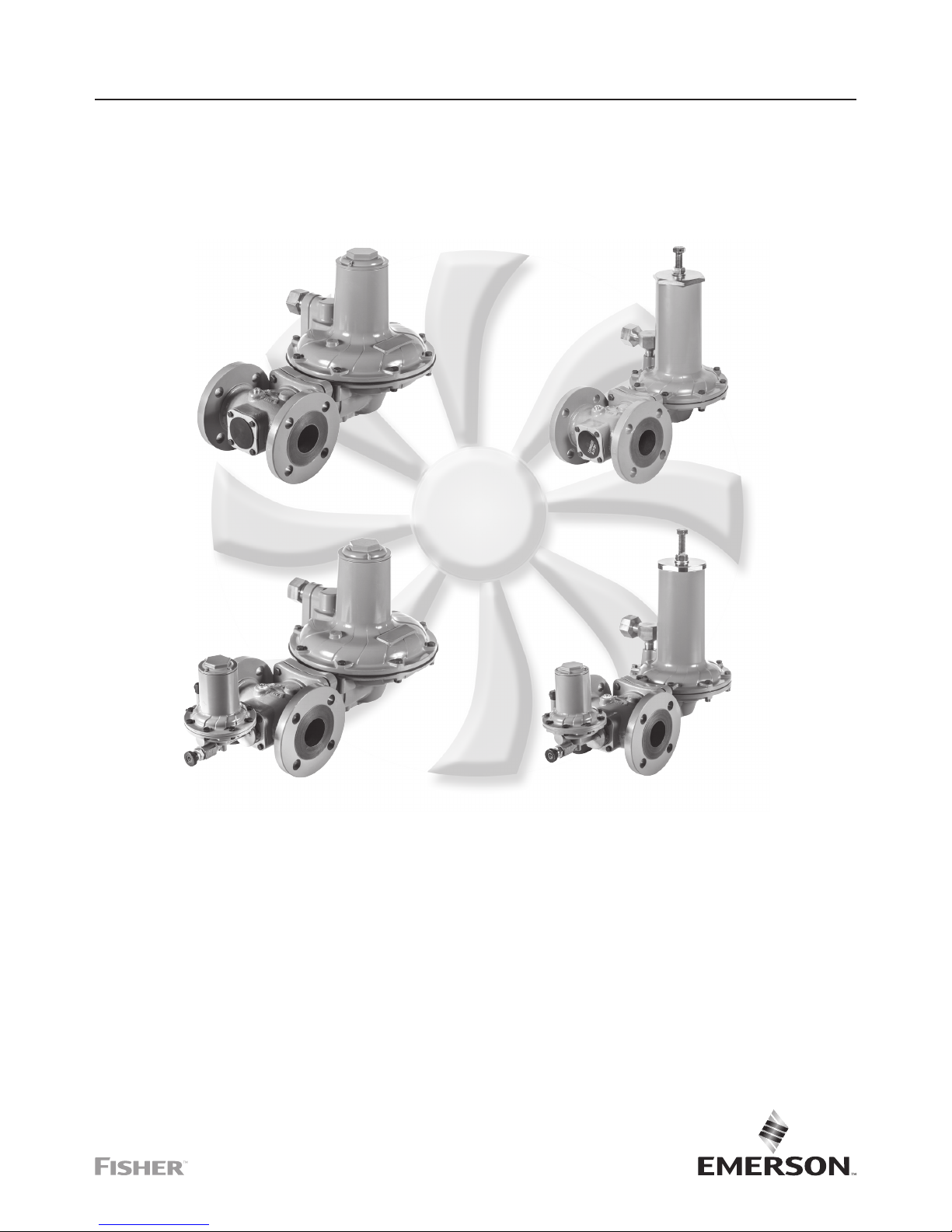
Table of Contents
Introduction ..................................... 1
Specications ...................................2
Principle of Operation .............................9
Installation and Overpressure Protection ..............9
Startup ........................................ 13
Adjustment. . . . . . . . . . . . . . . . . . . . . . . . . . . . . . . . . . . . . 13
Shutdown. . . . . . . . . . . . . . . . . . . . . . . . . . . . . . . . . . . . . . 14
Maintenance and Inspection .......................14
Parts Ordering .................................. 15
Parts List ......................................16
Introduction
Scope of the Manual
This Instruction Manual provides installation and
maintenance instructions and parts list information for
CSB700 Series regulators. Instructions and parts lists for
other equipment mentioned in this instruction manual are
found in separate manuals.
Figure 1. CSB700 Series Pressure Reducing Regulators
P2142
P2138 P2155
P2222
TYPE CSB700 REGULATOR
TYPE CSB750 HIGH PRESSURE
REGULATOR
TYPE CSB704 WITH
TYPE VSX8 SLAM-SHUT REGULATOR
TYPE CSB754 HIGH PRESSURE WITH
TYPE VSX8 SLAM-SHUT
CSB700 Series
Instruction Manual
D103483X012
October 2018
CSB700 Series Commercial / Industrial
Pressure Reducing Regulators
Page 2
Specifications
The Specifications section lists the specifications for the CSB700 Series regulators. The following information is stamped on
the nameplate of CSB700 Series: Type and Class, Maximum Outlet Pressure and Spring Range.
Available Configurations
See Table 1
Regulator Type
Differential Strength (DS)
Accuracy Class
Up to AC5 (depending on Outlet Pressure)
Lockup Class
Up to SG10 (depending on Outlet Pressure)
Failure Mode per EN334
Fail Open (FO)
Integral Strength (IS) Pressure Ratings
(1)
See Table 4
Differential Strength (DS) Pressure Ratings
(1)
See Table 5
Body Sizes, Materials, End Connections and
Pressure Ratings
(1)
See Table 6
Operating Pressure Range
(1)
Regulator: See Table 7
Slam-Shut Module:
See Tables 8a, 8b, 8c and 8d
Maximum Outlet Pressure
(1)
Emergency Casing:
Type CSB700/CSB700F/CSB720/CSB720F:
4.0 bar / 58.0 psig
Type CSB750: 5.0 bar / 72.5 psig
To Avoid Internal Metallic Parts Damage:
Type CSB700/CSB700F/CSB720/CSB720F:
0.34 bar / 5.0 psig over set pressure
Type CSB750: 1.5 bar / 21.8 psig — not to exceed
maximum emergency outlet
Operating Casing:
Type CSB700/CSB720: 1.1 bar / 16 psig
Type CSB750: 5.0 bar / 72.5 psig
Outlet Pressure Ranges
(1)
9.0 mbar to 4.0 bar / 0.13 to 58.0 psig
See Table 7
Orifice Size:
35 mm / 1-3/8 in.
Flow and IEC Sizing Coefficients:
See Table 5
Pressure Registration
External
Temperature Capabilities
(1)(2)(3)
According to PED Standards:
-20 to 66°C / -4 to 151°F
Non-PED:
-30 to 66°C / -22 to 151°F
Spring Case Vent Connection
1 NPT: Types CSB700 and CSB720
1/2 NPT: Type CSB750
Type VSX8 Slam-Shut Device Maximum Inlet
Pressure (P
umax
)
(1)
:
Differential Strength (DS): 16 bar / 232 psig
Integal Strength (IS): 6.0 bar / 87 psig
Approximate Weights
with Threaded body
Type CSB700/CSB720: 13 kg / 29 lbs
Type CSB750: 14 kg / 31 lbs
Type CSB704/CSB724: 14 kg / 31 lbs
Type CSB754: 15 kg / 33 lbs
with Flanged body
Add 5.2 kg / 11 lbs to weights listed
Designed, Tested and Evaluated Consistent With:
ANSI B16, ASME BPVC Sec. VIII Div. I, ASTM B117
(Corrosion Resistance), EN334 and EN14382
PED Conformity Statement and Information
The CSB700 Product Series is in conformity with the
Pressure Equipment Directive PED 2014/68/EU. Pressure
regulator does not require any supplementary upstream
safety accessory for protection against overpressure
compared with its design pressure PS, when upstream
reducing station is sized for a max downstream incidental
MIPd <= 1.1 PS.
PED Related Information
See Table 2
1. The pressure/temperature limits in this Instruction Manual or any applicable standard limitation should not be exceeded.
2. Standard token relief set values listed in Tables 8a, 8b, 8c and 8d are based on -20 to 60°C / -4 to 140°F.
3. Product has passed Emerson Process Management Regulator Technologies, Inc. (Emerson) testing for lockup, relief start-to-discharge and reseal down to -40°.
CSB700 Series
2
Page 3
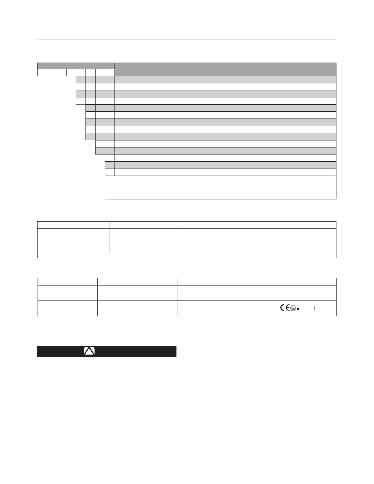
Table 2. PED Information
TYPE DESCRIPTION PED CATEGORY FLUID GROUP
CSB700, CSB700F, CSB720,
CSB720F and CSB750
Base regulator I
Groups 1 and 2 according to PED 2014/68/EU,
1st and 2nd family gas according to EN437 or
other gases (compressed air, nitrogen). The gas
must be non-corrosive, clean (ltration on inlet
side necessary) and dry.
CSB704, CSB704F, CSB724,
CSB724F and CSB754
Regulator with Slam-shut Module IV
European EN Reference Standards EN334, EN14382
Table 1. Available Congurations
TYPE NUMBER
OPTION
C S B 7
PRESSURE CONSTRUCTION
0 Low Pressure Applications (Outlet Pressure: 9.0 to 110 mbar / 3.6 in. w.c. to 1.6 psig)
(2)
2 Medium Pressure Applications (Outlet Pressure: 61 to 780 mbar / 0.9 to 11.3 psig)
(2)
5 High Pressure Applications (Outlet Pressure: 0.70 to 4.0 bar / 10.2 to 58.0 psig)
(2)
OVERPRESSURE PROTECTION
0 Without Overpressure Protection Module
0F Without Overpressure Protection Module (Outlet Pressure: 9.0 to 110 mbar / 3.6 in. w.c. to 1.6 psig and 270 to 325 mbar / 3.9 to 4.7 psig only)
(2)
4 With Type VSX8 Slam-shut Module
(1)
4F With Type VSX8 Slam-shut Module
(1)
(Outlet Pressure: 9.0 to 110 mbar / 3.6 in. w.c. to 1.6 psig and 270 to 325 mbar / 3.9 to 4.7 psig only)
(2
PRESSURE REGISTRATION
E External
RELIEF
N None
T Token Internal Relief
(3)
Example: Type number CSB724ET: Type CSB700 regulator constructed for medium pressure applications, with Type VSX8 Slam-shut Module, with
External pressure registration and with Token relief.
1. Reference Instruction Manual D103127X012 for information regarding the Type VSX8 Slam-shut Module.
2. The pressure/temperature limits in this Instruction Manual and any applicable standard or code limitation should not be exceeded.
3. Token relief not available for outlet pressure above 500 mbar / 8 psig.
.
!
WARNING
Failure to follow these instructions or to
properly install and maintain this equipment
could result in an explosion and/or fire
causing property damage and personal
injury or death.
Fisher™ regulators must be installed, operated
and maintained in accordance with federal,
state and local codes, rules and regulations
and Emerson instructions.
If the regulator vents gas or a leak develops
in the system, service to the unit may be
required. Failure to correct trouble could
result in a hazardous condition.
Call a gas service person to service the
unit. Only a qualified person must install or
service the regulator.
Table 3. Directive ATEX Information
TYPE CLASSIFICATION ATEX ASSEMBLIES ATEX LABELLING
CSB704, CSB704F,CSB724,
CSB724F, CSB754 version
with VSX8
Non-electrical equipment Not falling under the ATEX Directive 2014/34/EU No
CSB704, CSB704F, CSB724,
CSB724F and CSB754
with limit switch
Non-electric equipment equipped with an
electrical device falling under the scope of the
ATEX Directive 2014/34/EU
Constitutes an assembly according to the
ATEX Directive 2014/34/EU
2 G T
CSB700 Series
3
Page 4
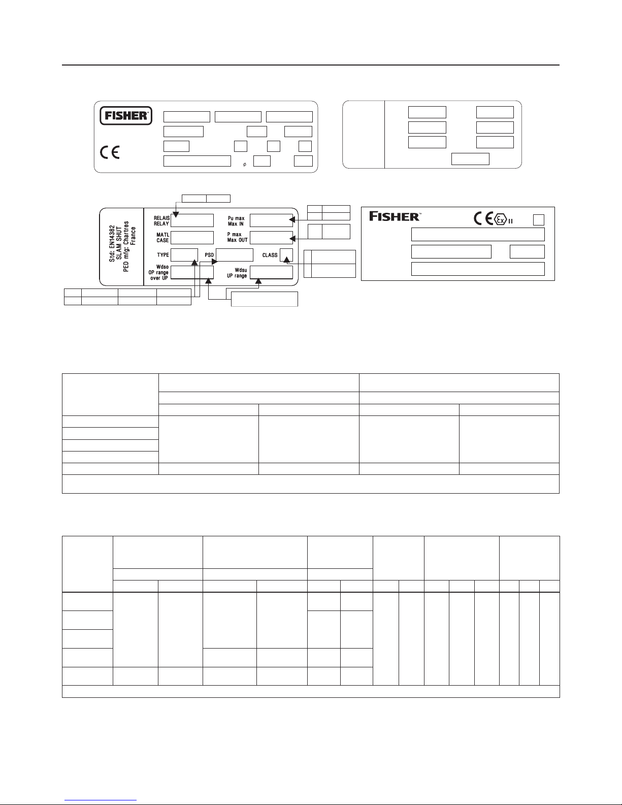
Table 4. Integral Strength (IS) Pressure Ratings
(1)
TYPE
MAXIMUM ALLOWABLE PRESSURE /
MAXIMUM EMERGENCY INLET PRESSURE
MAXIMUM OPERATING INLET PRESSURE
(2)
P
S
P
UMAX
bar psig bar psig
CSB700 and CSB704
4.0 58.0 4.0 58.0
CSB700F and CSB704F
CSB720 and CSB724
CSB720F and CSB724F
CSB750 and CSB754 5.0 72.5 5.0 72.5
1. Applicable only to applications where the inlet rating cannot exceed the outlet rating.
2. For the Integral Strength (IS version), the maximum value of P
s
and P
umax
should be similar to the PSD used for the Dierential Strength (DS) version.
Table 5. Dierential Strength (DS) Pressure Ratings and Flow and Sizing Coecients
TYPE
SPECIFIC MAXIMUM
ALLOWABLE PRESSURE /
MAXIMUM EMERGENCY
OUTLET PRESSURE
(1)
MAXIMUM ALLOWABLE PRESSURE /
MAXIMUM EMERGENCY INLET
PRESSURE
(1)
MAXIMUM
OPERATING INLET
PRESSURE
(1)
ORIFICE SIZE
WIDE-OPEN FLOW
COEFFICIENT
IEC SIZING
COEFFICIENT
P
SD
P
S
P
UMAX
bar psig bar psig bar psig mm In. C
g
C
v
C1XTFDF
L
CSB700 and
CSB704
4.0 58.0
12.0 174
10 145
35 1-3/8 1080 27.7 39 0.96 0.89 0.66
CSB700F and
CSB704F
6 87
CSB720F and
CSB724F
CSB720 and
CSB724
20.0 290 16 232
CSB750 and
CSB754
5.0 72.5 20.0 290 16 232
1. The pressure/temperature limits in this Instruction Manual and any applicable standard or code limitation should not be exceeded.
PATENT
PENDING
TS
REGULATOR SLAMSHUT SERIAL NO.
TEMP CLASS DOM
PS FLUID GROUP C AT LOC
Std: EN334
TYPE PSD
Pumax Pmax
Matl
Wds
Case
Failure Mode
REGULATOR
DN SEAT BODY
PN MATL
0062
PED mfg: Chartres,
France
Figure 2. CSB700 Series Regulator and Slam-shut Nameplates and Labels
REGULATOR NAMEPLATES
SLAM-SHUT NAMEPLATE NAMEPLATE FOR EXPLOSIVE ATMOSPHERE IF ATEX ASSEMBLED
Std: EN14382
SLAM-SHUT
PED mfg: Gallardon,
France
Pumax
Max IN
CLASS
TYPE
VSX8L VSX8H
VSX4L VSX4H
RELAIS
RELAY
Pdmax
Max OUT
MATL
CASE
Wdso
OP range
Alum
Pressure range following
service condition
IS 6 bar
DS 16 bar
LP 1.5 bar
HP 5.5 bar
PSD
Wdsu
UP range
A Min, Min and
Max installation
B Max installation
only
VSX8L VSX8H
IS 6.0 bar
DS 16.0 bar
LP 1.5 bar
HP 5.5 bar
IS PS 6.0 bar P
umax
6.0 bar PSD 6.0 bar
DS PS 20.0 bar P
umax
16.0 bar PSD 6.0 bar
Pressure range following
service condition
A Min, Min and
Max installation
B Max installation
only
No de Série
SERIAL No.
TYPE
FRANCEL SAS
Chartres FRANCE
An
YEAR
Utilisation
INTENDED USE
2 G T
CSB700 Series
4
Page 5
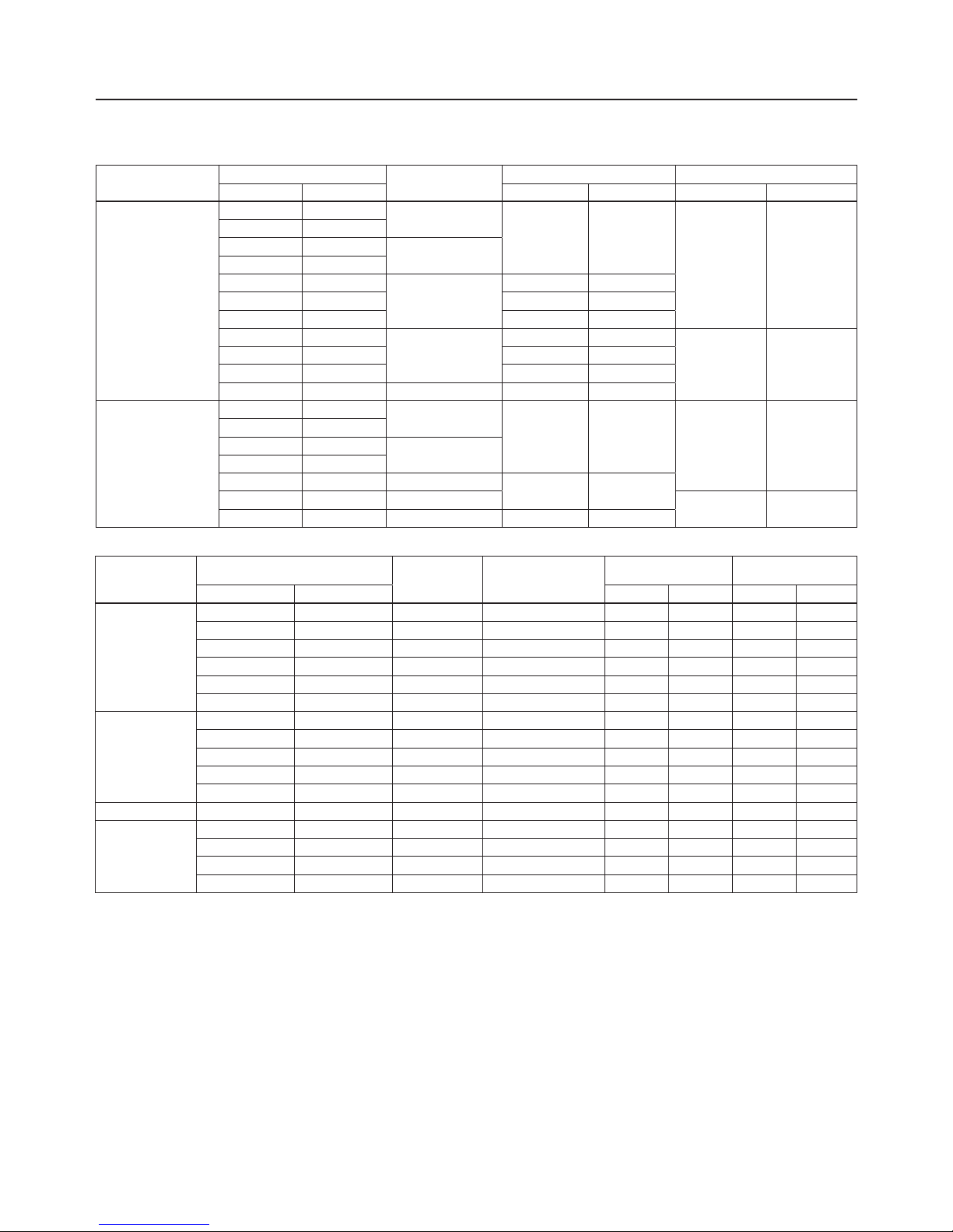
Table 6. Body Sizes, Material, End Connections and Cold Working Pressure Ratings
BODY MATERIAL
BODY SIZE
END CONNECTION
FACE-TO-FACE DIMENSION BODY PRESSURE RATING
DN NPS mm In. bar psig
Ductile Iron
40 1-1/2
NPT
155 6.10
17.2 250
50 2
40 1-1/2
Rp
50 2
50 2
CL125 FF/CL150 FF
191 7.52
50 2 254 10.0
50 2 267 10.5
50 2
PN 10/16
191 7.52
16.0 232
50 2 200 7.87
50 2 254 10.0
40 1-1/2 PN 16 Slip-On 222 8.74
WCC Steel
40 1-1/2
NPT
155 6.10
20.0 290
50 2
40 1-1/2
Rp
50 2
50 2 CL150 RF
254 20.0
50 2 PN 10/16
16.0 232
50 2 PN 10/16 191 7.52
Table 7. CSB700 Series Primary Regulator Outlet Pressure Ranges
TYPE
OPERATING PRESSURE RANGES, W
d
PART NUMBER
SPRING
COLOR
SPRING WIRE
DIAMETER
SPRING FREE LENGTH
mbar psig mm In. mm In.
CSB700, CSB704,
CSB700F and CSB704F
9 to 14 3.6 to 5.6 in.w.c. GE30336X012 Silver 3.00 0.118 224 8.82
13 to 24 5.2 to 9.6 in.w.c. ERSA01138A0 Red 3.50 0.138 264 10.4
22 to 39 8.8 to 15.7 in.w.c. GE30338X012 Black Stripe 4.32 0.170 172 6.78
32 to 50 12.8 to 20.1 in.w.c. GE30339X012 Purple 4.34 0.171 187 7.35
42 to 70 16.9 to 28.1 in.w.c. GE30340X012 White Stripe 4.62 0.182 188 7.40
61 to 110 0.9 to 1.6 ERSA03656A0 Dark Green 4.88 0.192 224 8.82
CSB720 and CSB724
61 to 110 0.9 to 1.6 ERSA03656A0 Dark Green 4.88 0.192 224 8.82
105 to 220 1.5 to 3.2 ERSA03657A0 Blue 5.94 0.234 217 8.53
210 to 380 3.1 to 5.5 GG06247X012 Black 8.00 0.315 206 8.13
320 to 570 4.6 to 8.3 ERSA01582A0 Red with White Stripe 8.71 0.343 177 6.97
510 to 780 7.4 to 11.3 ERSA05055A0 Blue with White Stripe 10 0.394 181 7.13
CSB720F and CSB724F 270 to 325 3.9 to 4.7 ERAA11747A0 Black with White Stripe 6.5 0.256 235 9.25
CSB750 and CSB754
0.7 to 1.19 bar 10.2 to 17.3 GE30345X012 Purple Stripe 9.00 0.354 225 8.87
1.05 to 2.7 bar 15.2 to 39.2 GE30346X012 Brown 11.0 0.433 226 8.88
2.3 to 3.25 bar 33.4 to 47.1 ERSA01125A0 Grey with Red Stripe 12.6 0.496 225 8.87
3.1 to 4 bar 45 to 58 ERSA01126A0 Grey with Orange Stripe 13.7 0.539 226 8.89
Description
CSB700 Series regulators are typically installed on industrial
and commercial applications. See Table 1 for Available
Configurations. Types under CSB700 Series are utilized
for high capacities. Low, Medium and High outlet pressure
constructions are available via Types CSB700, CSB720 and
CSB750 respectively, that provide outlet setpoints ranging
from 9.0 mbar to 4.0 bar / 0.13 to 58.0 psig.
The Types CSB704, CSB724 and CSB754 are examples of
CSB700 Series configurations that offer a slam-shut module
that shuts off the flow of gas to the downstream system in
the event of outlet pressure rising above or falling below the
predefined levels due to a failure.
Optional token relief is available, which acts as a low
capacity internal relief valve to relieve minor overpressure
situations due to nicks or other minor damage to the
orifice or disk or due to thermal expansion of the
downstream system.
External outlet pressure registration requires an external
control line/sense line.
CSB700 Series
5
Page 6
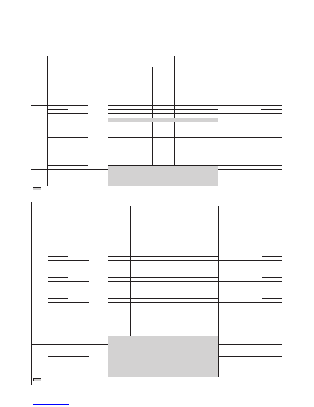
Table 8b. European Overpressure Shut-o OPSO Only Ranges
REGULATOR SLAM SHUT DEVICE
Type
Typical
Setpoint
Spring
Range
Type
(Maximum
Operating
Inlet)
Token
Relief Set
Relief Range Shown as a %
of Regulator Setpoint
Required Difference Between
Token Relief and OPSO
Over Pressure Shut-off
(OPSO) Set Range
Factory Set
OPSO
mbar mbar mbar min max mbar mbar mbar
CSB704F
10 9 to 14
VSX8L
(8.6 bar)
17 170 215 8
30 to 60 32
15 13 to 24 26 170 215 6
20
13 to 24
34 170 215 6
30 to 60 40
21 36 170 215 4
27
22 to 39
41 150 160 5
30 to 60
46
30 45 150 160 10 60
35 22 to 39 53 150 160 10 40 to 110 70
50
42 to 70
70 140 158 16
60 to 193
90
60 84 140 158 16 105
75 61 to 110 98 130 140 20 60 to 193 130
CSB704
10 9 to 14
VSX8L
(16 bar)
17 170 215 8
30 to 60
40
15 13 to 24 26 170 215 10 50
20
13 to 24
34 170 215 10
30 to 60
55
21 36 170 215 10 55
27
22 to 39
41 150 160 10
30 to 60
55
30 45 150 160 10 60
35 22 to 39 53 150 160 10 40 to 110 70
50
42 to 70
70 140 158 16
60 to 193
90
60 84 140 158 16 105
75 61 to 110 98 130 140 20 60 to 193 130
CSB724
100 61 to 110
VSX8L
(16 bar)
130 130 140 20 60 to 193 170
120
105 to 220
156 130 140 40
95 to 280
205
150 195 130 140 40 250
160 105 to 220 208 130 140 40 95 to 280 265
200 105 to 220 250 125 140 50 138 to 500 330
300 210 to 380 375 125 140 50 138 to 500 450
500 320 to 570 625 125 140 60 221 to 760 700
600
510 to 780
400 to 915
(1)
840
750 400 to 1100
(1)
1050
CSB724F 300 270 to 325
VSX8L
(8.6 bar)
138 to 500 450
CSB754
1000 700 to 1190
VSX8H
(16 bar)
400 to 1450 1320
1200
1050 to 2700 900 to 3000
1600
1500 1900
2000 1050 to 2700 1600 to 4000
(1)
2400
3000 2300 to 3250
1600 to 5000
(1)
3400
4000 3100 to 4000 4400
- Gray areas indicate that token relief is not available above 500 mbar setpoint.
1. Max OPSO setpoint truncated to reect maximum outlet pressure for spring range.
Table 8a. North American Overpressure Shut-o OPSO Only Ranges
REGULATOR SLAM SHUT DEVICE
Type
Typical
Setpoint
Spring
Range
Type
(Maximum
Operating
Inlet)
Token
Relief Set
Relief Range Shown as a %
of Regulator Setpoint
Required Difference Between
Token Relief and OPSO
Over Pressure Shut-off
(OPSO) Set Range
Factory Set
OPSO
psig psig psig min max psig psig psig
CSB704F
7 in. w.c.
5.2 to
9.6 in. w.c.
VSX8L
(125 psi)
12 in. w.c. 170 215 3.2 in. w.c. 12 to 24 in. w.c. 22 in. w.c.
11 in. w.c.
8.8 to
15.7 in. w.c.
17 in. w.c. 150 160 4 in. w.c. 16 in. w.c. to 1.6 psig 25 in. w.c.
14 in. w.c.
12.8 to
20.0 in. w.c.
21 in. w.c. 150 160 4 in. w.c. 24 in. w.c. to 2.8 psig 1.1
1
24 in. w.c. to
1.6 psig
1.4 140 150 6.4 in. w.c. 1.4 to 4.1 2
CSB724F
2
1.5 to 3.2
2.6 130 140 0.6
2.0 to 7.3
3.5
3 3.8 125 140 0.6 5
5 3.1 to 5.5 6.2 125 140 0.7 3.2 to 11.0 7
10 7.4 to 11.3 5.8 to 13.3
(1)
12
CSB704
7 in. w.c.
5.2 to
9.6 in. w.c.
VSX8L
(232 psi)
12 in. w.c. 170 215 3.2 in. w.c. 12 to 24 in. w.c. 22 in. w.c.
11 in. w.c.
8.8 to
15.7 in. w.c.
17 in. w.c. 150 160 4 in. w.c. 16 in. w.c. to 1.6 psig 25 in. w.c.
14 in. w.c.
12.8 to
20.0 in. w.c.
21 in. w.c. 150 160 4 in. w.c. 24 in. w.c. to 2.8 psig 1.1
1
24 in. w.c. to
1.6 psig
1.4 140 150 6.4 in. w.c. 1.4 to 4.1 2
CSB724
2
1.5 to 3.2
2.6 130 140 0.6
2.0 to 7.3
3.5
3 3.8 125 140 0.6 5
5 3.1 to 5.5 6.2 125 140 0.7 3.2 to 11.0 7
10 7.4 to 11.3 5.8 to 13.3
(1)
12
CSB754
15 10.2 to 17.3
VSX8H
(232 psi)
13.1 to 39.1
(1)
19
20
15.2 to 39.2 13.1 to 43.5
25
30 35
40 33.4 to 47.1 23.2 to 72.5
(1)
45
- Gray areas indicate that token relief is not available above 8 psig setpoint.
1. Max OPSO setpoint truncated to reect maximum outlet pressure for spring range.
CSB700 Series
6
Page 7
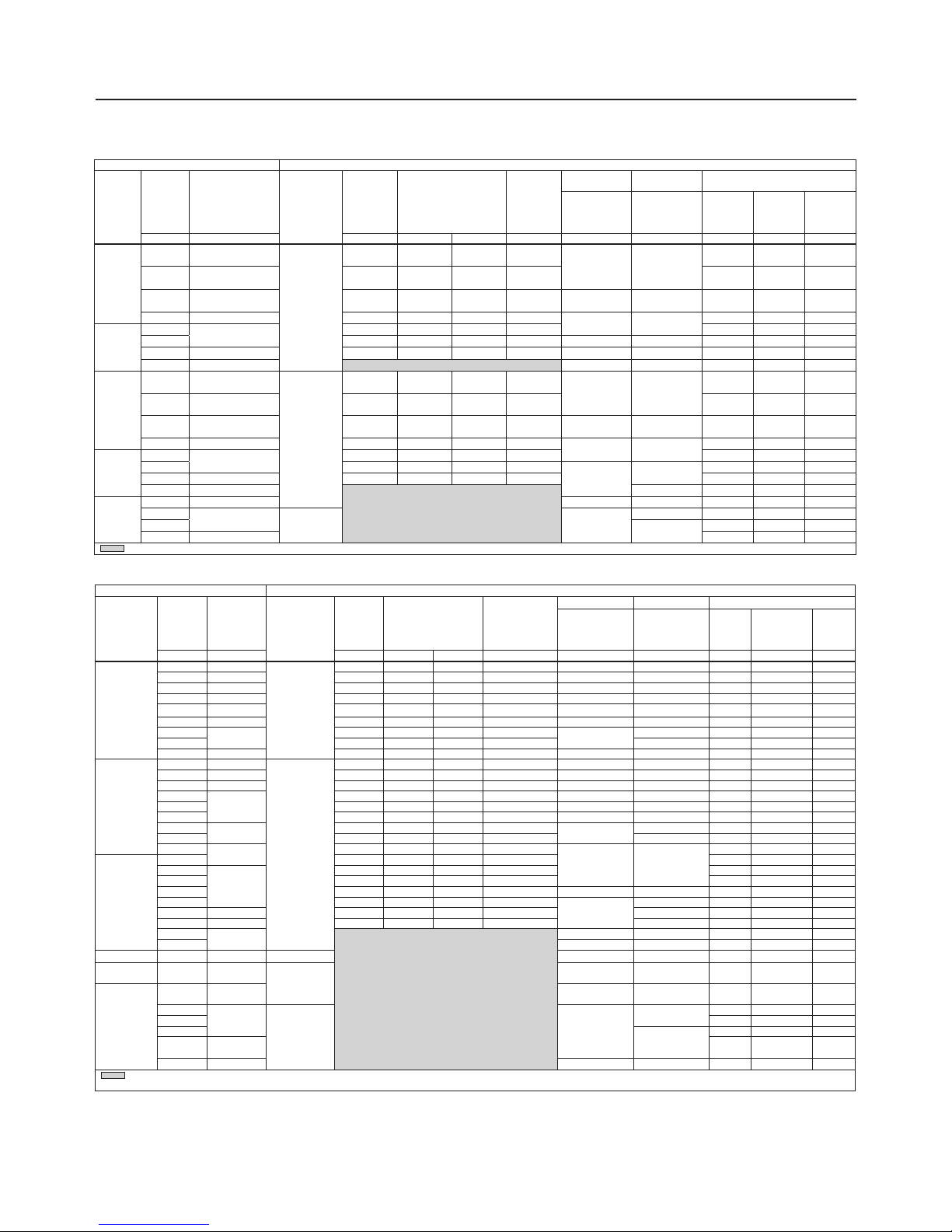
Table 8c. North American Overpressure and Underpressure Shut-o UPSO/OPSO Ranges
Table 8d. European Overpressure and Underpressure Shut-o UPSO/OPSO Ranges
Example: If a non-standard setpoint is needed, see the following example for the proper use of Tables 8a, 8b, 8c and 8d. In this
example, the non-standard regulator setpoint is 140 mbar / 2.0 psig. The minimum factory token relief set pressure is 130% of the
non-standard setpoint. The resulting token relief set pressure is 183 mbar / 2.6 psig. The minimum factory OPSO and UPSO set
pressures are 165% and 50% of the non-standard setpoint, respectively. The resulting minimum settings are: OPSO = 231 mbar /
3.4 psig and UPSO = 70 mbar / 1.0 psig.
REGULATOR SLAM SHUT DEVICE
Type
Typical
Setpoint
Spring
Range
Type
(Maximum
Operating
Inlet)
Token
Relief Set
Relief Range Shown
as a % of Regulator
Setpoint
Required
Difference
Between Token
Relief and
OPSO
UPSO OPSO Factory Set
Set Range
Shut-off (OPSO)
Set Range Over
UPSO Setpoint
UPSO
Adjusted
OPSO Range
OPSO
mbar mbar mbar min max mbar mbar mbar mbar mbar mbar
CSB704F
15 13 to 24
VSX8L (8.6 bar)
26 170 215 6 7 to 11 30 to 44 8 38 to 52 40
20 13 to 24 34 170 215 6 7 to 11 30 to 44 10 40 to 54 40
21 13 to 24 36 170 215 4 7 to 11 30 to 44 10 40 to 54 40
27 22 to 39 41 150 160 5 7 to 15 32 to 44 14 46 to 58 46
30 22 to 39 45 150 160 10 7 to 30 40 to 72 15 55 to 87 60
35 22 to 39 53 150 160 10 7 to 30 40 to 72 18 58 to 90 70
50
42 to 70
70 140 158 16
10 to 75
48 to 74 25 73 to 99 90
60 84 140 158 16 48 to 74 30 78 to 104 100
75 61 to 110 98 130 140 20 25 to 160 83 to 221 38 121 to 259 130
CSB704
15 13 to 24
VSX8L (16 bar)
26 170 215 6 7 to 30 40 to 55 8 48 to 63 50
20 13 to 24 34 170 215 6 7 to 30 40 to 55 10 50 to 65 55
21 13 to 24 36 170 215 4 7 to 30 40 to 55 10 50 to 65 55
27
22 to 39
41 150 160 5 7 to 30 40 to 55 14 54 to 69 55
30 45 150 160 10 7 to 30 45 to 76 15 60 to 91 60
35 53 150 160 10 7 to 30 45 to 76 18 63 to 94 70
50
42 to 70
70 140 158 16
10 to 75
50 to 80 25 75 to 105 90
60 84 140 158 16 50 to 80 30 80 to 110 100
75
61 to 110
98 130 140 20
25 to 160 83 to 221
38 121 to 259 130
CSB724
100 130 130 140 20 50 133 to 271 170
120
105 to 220
156 130 140 40 60 143 to 281 205
150 195 130 140 40 75 158 to 296 250
160 208 130 140 40 25 to 160 83 to 221 80 163 to 301 265
200 250 125 140 50
100 to 500
114 to 261 100 214 to 361 330
300 210 to 380 375 125 140 50 179 to 386 150 329 to 536 450
500 320 to 570 625 125 140 60 241 to 565 250 491 to 815 700
600
510 to 780
100 to 500 241 to 565 300 541 to 865 840
750 100 to 750 460 to 932 375 835 to 1120
(1)
1050
CSB724F 300 270 to 325 VSX8L (8.6 bar) 100 to 500 179 to 386 200 379 to 586 400
CSB754 GrDF 1 bar
0.7 to
1.19 bar
VSX8L (16 bar)
100 to 500 460 to 932 750 1210 to 1682 1210
CSB754
1 bar
0.7 to
1.19 bar
100 to 500 460 to 932 500 960 to 1432 1320
1.2 bar
1.05 to
2.7 bar
VSX8H (16 bar)
500 to 2000
1050 to 1570
600 1650 to 2170 1650
1.5 bar 750 1800 to 2320 1900
2 bar
1250 to 2300
1000 2250 to 3300 2400
3 bar
2.3 to
3.25 bar
1500 2750 to 3800 3400
4 bar 3.1 to 4 bar 500 to 2800 2100 to 3750 2000 4100 to 5000
(1)
4400
- Gray areas indicate that token relief is not available above 500 mbar setpoint.
1. Max OPSO setpoint truncated to reect maximum outlet pressure for spring range.
REGULATOR SLAM SHUT DEVICE
Type
Typical
Setpoint
Spring Range
Type
(Maximum
Operating
Inlet)
Token
Relief Set
Relief Range Shown
as a % of Regulator
Setpoint
Required
Difference
Between
Token
Relief and
OPSO
UPSO OPSO Factory Set
Set Range
Shut-off (OPSO)
Set Range Over
UPSO Setpoint
UPSO
Adjusted
OPSO
Range
OPSO
psig psig psig min max psig psig psig psig psig psig
CSB704F
7 in. w.c. 5.2 to 9.6 in. w.c.
VSX8L
(125 psi)
12 in. w.c. 170 215 3.2 in. w.c.
3 to 12 in. w.c. 16 to 29 in. w.c.
3 in. w.c.
19 in. w.c.
to 1.2 psig
22 in. w.c.
11 in. w.c. 8.8 to 15.7 in. w.c. 17 in. w.c. 150 160 4 in. w.c. 6 in. w.c.
22 in. w.c.
to 1.3 psig
25 in. w.c.
14 in. w.c. 12.8 to 20.0 in. w.c. 21 in. wc 150 160 4 in. w.c.
4 in. w.c. to
1.1 psig
20 in. w.c. to
1.8 psig
9 in. w.c.
1 to
2.1 psig
1.1
1 24.0 in. w.c. to 1.6 psig 1.4 140 150 6.4 in. w.c.
10 in. w.c. to
2.3 psig
1.2 to 3.2
14 in. w.c. 1.7 to 3.7 2
CSB724F
2
1.5 to 3.2
2.6 130 140 0.6 1 2.2 to 4.2 3.5
3 3.8 125 140 0.6 1.5 to 7.3 2.6 to 5.6 2 4.6 to 7.6 5
5 3.1 to 5.5 6.2 125 140 0.7 1.5 to 7.3 3.5 to 8.2 3 5.6 to 8.6 7
10 7.4 to 11.3 1.5 to 7.3 3.5 to 8.2 5 8.5 to 13.2 12
CSB704
7 in. w.c. 5.2 to 9.6 in. w.c.
VSX8L
(232 psi)
12 in. w.c. 170 215 3.2 in. w.c.
3 to 12 in. w.c. 18 to 30 in. w.c.
3 in. w.c.
21 in. w.c.
to 1.2 psig
22 in. w.c.
11 in. w.c. 8.8 to 15.7 in. w.c. 17 in. w.c. 150 160 4 in. w.c. 6 in. w.c.
24 in. w.c.
to 1.3 psig
25 in. w.c.
14 in. w.c. 12.8 to 20.0 in. w.c. 21 in. w.c. 150 160 4 in. w.c.
4 in. w.c. to
1.1 psig
25 in. w.c. to
1.9 psig
9 in. w.c. 1.2 to 2.2 1.1
1 24.0 in. w.c. to 1.6 psig 1.4 140 150 6.4 in. w.c.
10 in. w.c. to
2.3 psig
1.2 to 3.2
14 in. w.c. 1.7 to 3.7 2
CSB724
2
1.5 to 3.2
2.6 130 140 0.6 1 2.2 to 4.2 3.5
3 3.8 125 140 0.6
1.5 to 7.3
2.6 to 5.6
2 4.6 to 7.6 5
5 3.1 to 5.5 6.2 125 140 0.7 3 5.6 to 8.6 7
10 7.4 to 11.3 3.5 to 8.2 5 8.5 to 13.2 12
CSB754
15 10.2 to 17.3 1.5 to 10.9 6.7 to 13.5 7 13.7 to 20.5 19
20
15.2 to 39.2
VSX8H
(232 psi)
7.3 to 29.0
15.2 to 22.8 10 25.2 to 32.8 25
30
18.1 to 33.4
15 33.1 to 48.4 35
40 33.4 to 55.1 20 38.1 to 53.4 45
- Gray areas indicate that token relief is not available above 8 psig setpoint.
CSB700 Series
7
Page 8
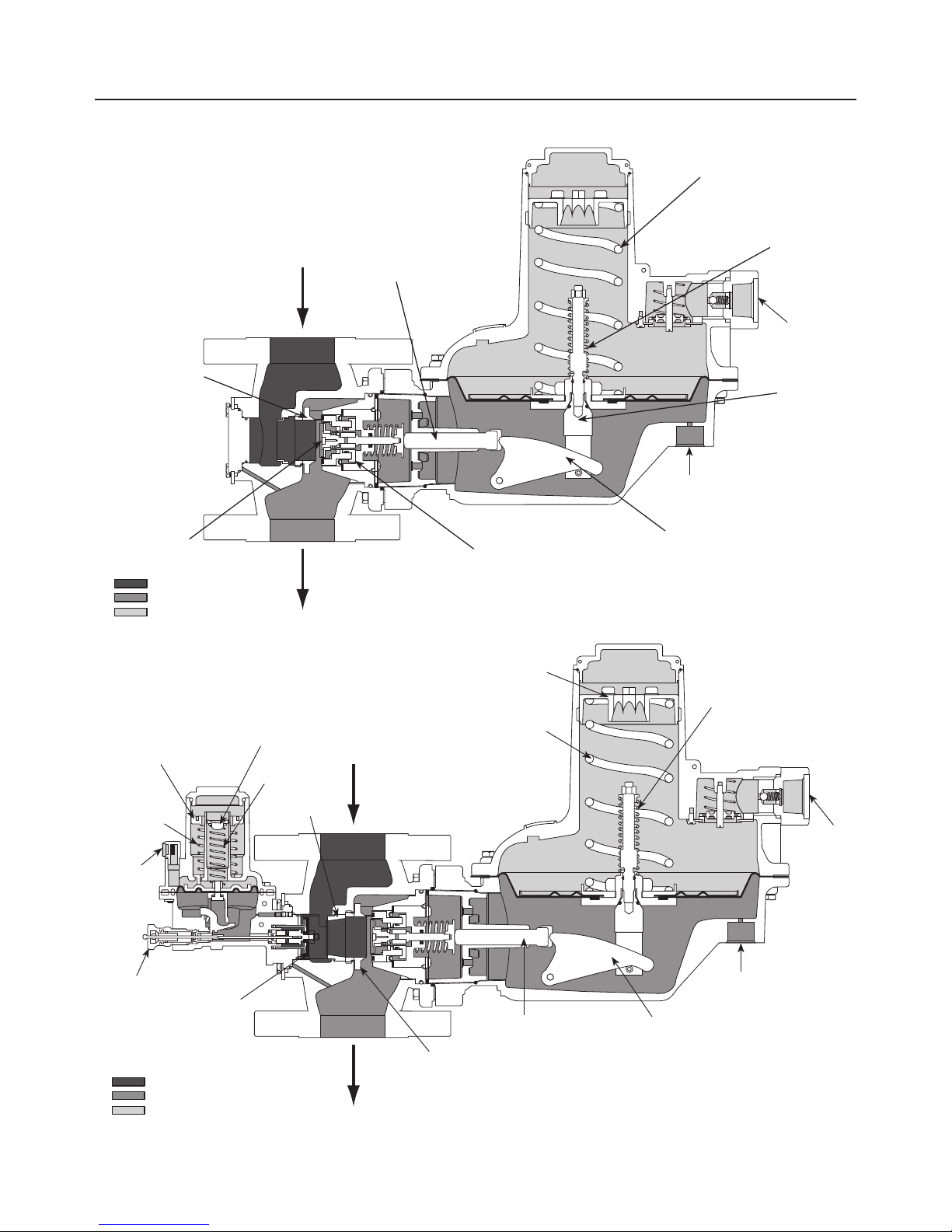
ERSA01618_02
ERSA01618_06
Figure 4. Type CSB704ET, Externally Registered Regulator and Slam-Shut Operational Schematic
Figure 3. CSB700 Series with External Registration Operational Schematics
INLET PRESSURE
OUTLET PRESSURE
ATMOSPHERIC PRESSURE
CONTROL SPRING
TOKEN RELIEF
SPRING
PUSHER POST
LEVER
BALANCED PORT ASSEMBLY
REGULATOR ORIFICE
REGULATOR DISK
VALVE STEM
EXTERNAL CONTROL
LINE (SENSE LINE)
INLET PRESSURE
OUTLET PRESSURE
ATMOSPHERIC PRESSURE
PRIMARY REGULATOR
TYPE VSX8 SLAM-SHUT MODULE
VENT
OPSO SET
SPRING
UPSO SPRING
UPSO
ADJUSTING
SCREW
OPSO
ADJUSTING
SCREW
SLAM-SHUT
ORIFICE
REGULATOR ORIFICE
VALVE STEM
LEVER
EXTERNAL CONTROL
LINE (SENSE LINE)
REGULATOR CONTROL SPRING
REGULATOR ADJUSTING SCREW
TOKEN RELIEF
SPRING
VENT
VENT
RESET KNOB
SLAM-SHUT DISK
CSB700 Series
8
Page 9

Principle of Operation
Type CSB700 Base Regulator Operation
Refer to Figure 3. When downstream demand decreases,
the pressure under the regulator diaphragm increases.
This pressure overcomes the regulator setting which
is set by the regulator control spring. The action of the
pusher post assembly, lever, and valve stem moves the
balanced port assembly closer to the orifice and reduces
gas flow. If downstream demand increases, pressure
under the regulator diaphragm decreases. Spring force
pushes the pusher post assembly downward, the balanced
port assembly moves away from the orifice and the gas
flow increases downstream as the regulator opens in
response to the decreased pressure underneath the
regulator diaphragm.
Type numbers with a “T”, for example Type CSB700ET,
provide a token or low capacity relief. The token relief
provides relief from minor overpressure caused by nicks or
dents on the orifice or by thermal expansion of gas in the
downstream line. Token relief also provides a token or signal,
in the form of odor, that indicates an overpressure situation
is occurring.
Type CSB704/CSB704F/CSB724/CSB724F/
CSB754 Slam-Shut Operation
The Type VSX8 slam-shut module on the Type CSB704
regulator is a fast-acting shutoff device that provides
overpressure (OPSO) or over and underpressure
(OPSO/UPSO) protection by completely shutting off the
flow of gas to the downstream system. See Table 8 for
guidance regarding the typical setpoints of the regulator
and associated slam-shut module OPSO and combined
OPSO and UPSO setpoints. The Type VSX8’s actions
are independent of the Type CSB704 regulator and of
variations to the inlet pressure. The Type VSX8 comes
standard with external downstream pressure registration.
External registration requires a downstream sensing line.
See Figure 6 for guidance regarding installation of the
downstream control line.
The Type VSX8 shutoff disk is normally in the open (reset)
position, see Figure 4. If the downstream pressure below
the slam-shut diaphragm increases (or decreases) until
it reaches the slam-shut setpoint, this diaphragm moves
upward (or downward) to release the trip mechanism which
allows the spring force on the stem to push the disk against
the seat, shutting off all gas flow. To reset the slam-shut
after gas flow has been shut off, refer to the Type VSX8
Instruction Manual for additional details D103127X012.
!
WARNING
In order for the Underpressure Shutoff
(UPSO) of any slam-shut to be triggered,
the downstream pipe pressure must drop
below the UPSO setpoint. In the case of a
downstream line break, numerous factors
can prevent the downstream pipe pressure
from decreasing below the slam-shut UPSO
setpoint. These factors include the distance
of pipe to the break, the diameter of the
pipe, size of the break and the number of
restrictions, such as valves, elbows and
bends, downstream of the regulator and/
or slam-shut device. Due to these factors
additional protections should be installed to
stop flow in the event of a line break.
Installation and
Overpressure Protection
Install in accordance with provisions of EN12186 / EN12279.
!
WARNING
Personal injury or system damage may
result if this regulator is installed, without
appropriate overpressure protection, where
service conditions could exceed the limits
given in the Specifications section and/or
regulator nameplate. Regulator and equipment
installation should be adequately protected
from physical damage.
All vents should be kept open to permit
free flow of gas to the atmosphere. Protect
openings against entrance of rain, snow,
insects or any other foreign material that
may plug the vent or vent line. On outdoor
installations, point the spring case vent
downward, see Figures 5 through 6. This
minimizes the possibility of freezing and of
water or other foreign materials entering the
vent and interfering with proper operation.
For Type CSB704/CSB704F/CSB724/ CSB724F/
CSB754 with Slam-shut, point the vents of
both the primary regulator and slam-shut
downward to resist collection of precipitation
and moisture. From the factory, the slam-shut
vent will always point in the same direction as
that of the primary regulator.
CSB700 Series
9
Page 10

Figure 5. CSB700 Series Regulator Installed with the Vent Pointed Downward and with a
Type 289H Relief Valve for High Capacity Relief
Figure 6. Type CSB704 Downstream Control Line Installation
CSB700 SERIES
REGULATOR
PROTECT VENT PIPE
WITH RAIN CAP
DN 50 / NP S 2 TYPE 289H
RELIEF VALVE
PRIMARY REGULATOR
SLAM SHUT
UPSTREAM
BLOCK VALVE
DOWNSTREAM
BLOCK VALVE
MINIMUM OF 6 X OUTLET
PIPING DIAMETER
INLET PRESSURE
OUTLET PRESSURE
INLET PRESSURE
OUTLET PRESSURE
ATMOSPHERIC PRESSURE
M1063
ATMOSPHERIC PRESSURE
CSB700 Series
10
Page 11

Under enclosed conditions or indoors,
escaping gas may accumulate and be
an explosion hazard. In these cases,
the vent should be piped away from the
regulator to the outdoors. See Vent Line
Installation section for the recommended
venting practice.
CAUTION
CSB700 Series regulators have an outlet
pressure rating lower than their inlet
pressure rating. If actual inlet pressure can
exceed the outlet pressure rating, outlet
overpressure protection is necessary.
However, overpressuring any portion of
the regulators beyond the limits in the
Specifications section may cause leakage,
damage to regulator parts or personal injury
due to bursting of pressure-containing parts.
Some type of external overpressure
protection should be provided to the
CSB700 Series if inlet pressure will be
high enough to damage downstream
equipment. Common methods of external
overpressure protection include relief valves,
monitoring regulators, shutoff devices and
series regulation.
If the regulator is exposed to an
overpressure condition, it should be
inspected for any damage that may have
occurred. Regulator operation below the
limits specified in the Specifications section
and regulator nameplate does not preclude
the possibility of damage from external
sources or from debris in the pipeline.
!
WARNING
The usage of an assembly incorporating
an electrical accessory in an explosive
atmosphere the Type CSB704 regulators
equipped with an electrical accessory (proxy,
microswitch) are:
– are classified “assembly” in conformity
with the ATEX Directive 2014/34/EU (ref
CEN/SFG-I Guidance sheet-February 2015)
– can be installed in any type of classified
zones according to the Directive
1999/92/EC dated 16 December 1999,
according to the following conditions:
a.) the equipment is connected to a
suitable and certified intrinsically
safe apparatus/electric circuit
(zener barrier)
b.) the equipment is used according to
the appropiate instruction manual
issued by the manufactuer and/or
available on our website
c.) when the equipment is used in a
natural gas pressure reducing and/or
metering station in compliance with
the following European standards:
EN 12186, EN 12279 and EN 1776.
General Installation Instructions
Before installing the regulator:
• Check for damage, which might have occurred
during shipment.
• Check for and remove any dirt or foreign material, which
may have accumulated in the regulator body.
• Blow out any debris, dirt or copper sulfate in the copper
tubing and the pipeline.
• Apply pipe compound to the external threads of the pipe
before installing the regulator.
• Make sure gas flow through the regulator is in the same
direction as the arrow on the body.
• Verify that:
- Equipment limits of utilization (PS, TS) correspond to
the desired operating conditions.
- The inlet is protected by an appropriate device(s) to
avoid exceeding the allowable limits (PS, TS).
• When designing a pressure reducing station, make an
analysis if it is necessary to take into account the effect
of wind, snow and temperature to avoid unnecessary
load and movement to the flanges of the equipment.
• If needed, a support may be used under the piping and
regulator/slam-shut body to avoid excessive pressure
force on the regulator/slam-shut.
Installation Location
• The installed regulator should be adequately
protected from vehicular traffic and damage from other
external sources.
• Install the regulator with the vent pointed vertically down,
see Figures 5 through 6. If the vent cannot be installed
in a vertically down position, the regulator must be
installed under a separate protective cover. Installing
the regulator with the vent down allows condensation to
drain, minimizes the entry of water or other debris from
entering the vent and minimizes vent blockage from
freezing precipitation.
CSB700 Series
11
Page 12

• Do not install the regulator in a location where there
can be excessive water accumulation or ice formation,
such as directly beneath a downspout, gutter or roof
line of building. Even a protective hood may not provide
adequate protection in these instances.
• Install the regulator so that any gas discharge through
the vent or vent assembly is over 0.91 m / 3 ft away from
any building opening.
Regulators Subjected to Heavy
Snow Conditions
Some installations, such as in areas with heavy snowfall,
may require a hood or enclosure to protect the regulator
from snow load and vent freeze over.
Downstream Control Line Installation
!
WARNING
Failure to install a downstream control line
could result in a hazardous condition. Install
downstream control line(s) to the slam-shut
device when construction uses external
pressure registration. The regulator and
slam-shut device will not control pressure
or shut off if a downstream control line is
not installed on those constructions where
external pressure registration is required.
CSB700 Series regulators with an “ET” or “EN” in the type
number use external pressure registration. To communicate
the downstream pressure to the regulator, connect a
downstream control line tubing to the 3/4 NPT control line
tapping in the lower diaphragm casing and connect the other
end of the tubing downstream of the regulator outlet with a
minimum distance of 6 times the outlet pipe diameter.
For all types with external control lines, use tubing with an
inner diameter of 16 mm / 0.63 in. or larger.
Downstream Control Line Installation with
Slam-Shut Device
Refer to Figure 6. When installing the Types CSB704ET,
CSB704FET, CSB704FEN CSB704EN, CSB724ET,
CSB724EN, CSB724FET, CSB724FEN and CSB754EN
regulators, connect downstream control line tubing to the
lower casing of the regulator and run the tubing downstream
of the regulator outlet with a minimum distance of 6 times
the outlet pipe diameter. Connect a second, separate
downstream control line tubing to the lower casing of
the slam-shut and run the tubing downstream of the
regulator outlet a minimum distance of 6 times the outlet
pipe diameter.
For all types with external control lines, use tubing with an
inner diameter of 16 mm / 0.63 in. or larger for the primary
regulator and 6.4 mm / 0.25 in. or larger for the slam-shut.
Installation with External Overpressure Protection
If the regulator is used in conjunction with a Type 289H
relief valve, it should be installed as shown in Figure 5.
The outside end of the vent line should be protected with a
rainproof assembly. The Type 289H is typically set 25 mbar /
10 in. w.c. higher than the outlet pressure setting of the
regulator, up to 75 mbar / 30 in. w.c. outlet pressure. For
pressure greater than this, set the Type 289H 0.05 bar /
0.73 psi higher than the outlet pressure setting of the
regulator. Refer to the 289 Series Instruction Manual
(D100280X012) for more information.
Vent Line Installation
CSB700 Series regulators have a 1 NPT screened vent
opening in the spring case. If necessary to vent escaping
gas away from the regulator, install a remote vent line in
the spring case tapping. Vent piping should be as short
and direct as possible with a minimum number of bends
and elbows. The remote vent line should have the largest
practical diameter. Vent piping on regulators with token relief
must be large enough to vent all relief valve discharge to
atmosphere without excessive backpressure and resulting
excessive pressure in the regulator.
For types with optional token relief, this low capacity relief
is located in the spring case of the primary regulator. If
necessary to vent escaping gas away, install a remote vent
line in the spring case tapping of the primary regulator as
described above. Periodically check all vent openings to be
sure that they are not plugged or obstructed.
For Types CSB700/CSB700F/CSB720/CSB720F, outlet
pressure higher than 0.34 bar / 5.0 psig above the setpoint
may damage internal metallic parts. For Type CSB750,
outlet pressure higher than 1.5 bar / 21.8 psig above the
setpoint may damage internal metallic parts. The maximum
emergency (casing) outlet pressure for all types is
4.0 bar / 58 psig except for Type CSB750 which is
5.0 bar / 72.5 psig.
CSB700 Series
12
Page 13

Startup
CAUTION
Pressure gauges must always be
used to monitor downstream pressure
during startup.
With the downstream system depressurized, use the
following procedure to start up the regulator.
1. Check to see that all appliances are turned off.
2. Slowly open the upstream shutoff valve.
3. Check inlet and outlet pressure for correct values.
4. Check all connections for leaks.
5. Turn on utilization equipment and recheck
the pressures.
Adjustment
Note
For types that include the slam-shut module,
refer to the instruction manual for Type VSX8
slam-shut (D103127X012) for adjustment and
maintenance of the slam-shut.
The range of allowable pressure settings for
the primary regulator is printed or stamped
on the nameplate. If the required setting is
not within this range, substitute the correct
spring (as shown in Table 7). If the spring is
changed, change the nameplate to indicate
the new pressure range.
A pressure gauge must always be used
to monitor downstream pressure while
adjustments are being made.
For Types CSB700, CSB700F, CSB720F
and CSB720
!
WARNING
During setpoint adjustment, do not mistake
the Token Relief Spring Nut (key 46) for
the main spring adjusting screw. Turning
the Token Relief Spring Nut will change
the token relief setting and if rotated
counterclockwise could result in gas
discharge and possible personal injury.
1. Remove the closing cap (key 60, Figure 12).
2. To increase the outlet setting, turn the adjusting screw
(key 65) clockwise. To decrease the outlet setting, turn
the adjusting screw counterclockwise.
3. Replace the closing cap (key 60).
For Type CSB750
1. Loosen the hex nut (key 67, Figure 12).
2. To increase the outlet setting, turn the adjusting bolt
(key 64) clockwise. To decrease the outlet setting, turn
the adjusting bolt counterclockwise.
3. Tighten the hex nut (key 67).
CSB700 Series with Slam-Shut
When adjusting the primary regulator and slam-shut for
operation, reference Table 8 for the OPSO setpoints and
combined OPSO and UPSO setpoints of the slam-shut
module for the given regulator spring ranges.
Resetting Type VSX8 Slam-Shut after
Overpressure/Underpressure
CAUTION
Internal regulator parts and installed
downstream equipment can be damaged
if the following procedure in resetting the
Type VSX8 controller is not followed.
If the regulator is exposed to an
overpressure condition, it should be tested
for lockup or shut-off after reseting the
slamshut to verify the regulator is not
damaged. Regulator operation below the
limits specified in the Specifications section
and regulator nameplate does not preclude
the possibility of damage from external
sources or from debris in the pipeline.
1. Slowly pull the reset button (refer to Type VSX8
Instruction Manual D103127X012) away from the
controller. This slow movement allows for a slow bleed
of the pressure across the controller’s disk and seat
area. The operator should be able to hear the pressure
bleeding through the system.
2. When the pressure has equalized and the air
bleeding sound has dissipated, the reset button (refer
to Type VSX8 Instruction Manual D103127X012)
should be pulled completely away from the controller
by hand until the internal shut-off mechanism has
been re-latched.
3. Once the operator feels the click of the re-latch
occurring, the reset button (refer to Type VSX8
Instruction Manual D103127X012) should be pushed
completely back into its original position.
4. It is recommended to test the regulator for lockup or
shut-off after resetting the slam-shut.
CSB700 Series
13
Page 14

Shutdown
Installation arrangements may vary, but in any installation
it is important that the valves be opened or closed slowly
and that the outlet pressure be vented before venting
inlet pressure to prevent damage caused by reverse
pressurization of the regulator. The steps below apply to the
typical installation as indicated.
1. Slowly close the upstream shutoff valve
2. Open vent valves downstream of the regulator.
3. Inlet pressure should automatically be released
downstream as the regulator opens in response to the
lowered pressure under the diaphragm.
4. Close outlet shutoff valve.
Maintenance and Inspection
!
WARNING
To avoid personal injury or equipment
damage, do not attempt any maintenance
or disassembly without first isolating
the regulator from system pressure and
relieving all internal pressure as described in
“Shutdown” section.
Regulators that have been disassembled for
repair must be tested for proper operation
before being returned to service. Only parts
manufactured by Emerson should be used
for repairing Fisher™ regulators. Restart
gas utilization equipment according to
normal startup procedures.
Due to normal wear or damage that may
occur from external sources, this regulator
should be inspected and maintained
periodically. The frequency of inspection
and replacement depends on the severity
of service conditions or the requirement of
local, state and federal rules and regulations.
In accordance with the applicable National or
Industry codes, standards and regulations/
recommendations, all hazards covered by
specific tests after final assembly and before
applying the CE marking, shall be covered
also after every subsequent reassembly
at installation site, in order to ensure that
the equipment will be safe throughout its
intended life.
Periodic inspection must be performed on
the CSB700 Series that include the slam-shut
overpressure protection module to ensure
protection of the downstream system in the
event the primary regulator losses pressure
control. This inspection must test that slamshut functions as intended.
Main Diaphragm Maintenance
CAUTION
For version with token relief measure the
distance before disassembly and note for
reassembly (see Figure 10).
Failure to follow the instructions regarding
measurement could impact the token
relief’s set-point
Perform the following steps to disassemble, inspect and
replace the main diaphragm:
1. Remove the closing cap (key 60, Figure 12) or loosen
hex nut (key 67). Turn the adjusting screw (key 65)
or adjusting bolt (key 64) counterclockwise to ease
spring compression.
Note
When disassembling a CSB700 Series
regulator, support the adjusting screw
(key 65) to prevent damage or contamination
due to falling.
2. Remove the adjusting screw (key 65) or the adjusting
bolt (key 64), then the bonnet (key 61), upper spring
seat (key 63) and sealing washer (key 113). Check the
sealing washer and replace if damaged. Remove the
spring (key 38).
3. Remove hex nuts (key 16, Figure 7 or 8) and bolt
(key 15). Separate the upper spring case (key 1) from
the lower casing assembly (key 9).
Note
When disassembling a CSB700 Series
regulator, lift the upper spring case (key 1,
Figure 7 or 8) straight up in order to avoid
hitting the stem (key 44).
4. Slide the diaphragm assembly (key 55, Figure 10) away
from the body (key 70) to unhook the pusher post from
the lever (key 10). Lift out the diaphragm assembly
(key 55) and its attached parts like pusher post (key 50)
and relief valve seat (key 51).
5a. For non-relieving units such as Type CSB700EN, see
Figure 10 — Non-relief assembly. Remove the screw
(key 45) and nut (key 40) to separate relief valve spring
seat (key 43), diaphragm assembly (key 55) and pusher
post (key 50). Check the diaphragm (key 55A) for damage
and replace if necessary.
CSB700 Series
14
Page 15

5b. For units with token relief such as Type CSB700ET,
see Figure 10 — Token Relief Assembly. Remove
token relief nut (key 46), spring retainer (key 42), relief
spring (key 41), nut (key 40) and relief valve spring
seat (key 43). Unscrew the stem (key 44) to separate
diaphragm assembly (key 55) and pusher post (key 50).
Check the diaphragm (key 55A) for damage and replace
if necessary.
Note
The diaphragm assembly (key 55) and the
upper spring case and lower casing must be
reassembled in a level, horizontal orientation
to ensure the relief stem is centered in the
upper spring case during use.
6. Reassemble the diaphragm assembly (key 55) unit in
the reverse order of the above steps. Assembly torques
for the diaphragm assembly are provided in Figure 10.
Before tightening the screw (key 45, for non-relief)
or stem (key 44, for token relief) into the pusher post
(key 50), place the loosely-assembled diaphragm
assembly (key 55) into position in the lower casing
(key 9, Figure 7 or 8), being sure that the pusher post is
hooked on the lever (key 10, Figure 7 or 8). Rotate the
diaphragm so that the diaphragm and lower casing holes
are aligned. Tighten the stem or screw using the proper
torque values (see Figure 10).
7. Reassemble the remaining parts by following steps 1 to 3
in reverse order. Tighten the hex nuts (key 16) and bolts
(key 15) in a crisscross pattern and tighten to the proper
torque value (see Figure 7 or 8).
Valve Disk, Balanced Port
Assembly Diaphragm and Regulator
Orifice Maintenance
Perform the following steps to disassemble, inspect and
replace the Valve Disk, Balanced Port Assembly Diaphragm
and Regulator Orifice:
1. Remove the cap screw (key 71, Figure 7 or 8) which
hold the lower spring casing (key 9) to the body
(key 70). Separate the lower spring casing from
the body.
2. Check the body O-ring (key 19 or key 21) for wear
replace if damaged.
3. Remove the balanced port assembly (key 36, Figure 7
or 8) from the body (key 70).
4. Examine the valve disk (key 36J, Figure 9) for nicks or
other damage. If damage is present, replace both the
disk and the balanced port diaphragm (key 36E) and
associated diaphragm O-ring (key 36N), that comes
into direct contact with the inner flange of the balanced
port diaphragm. Start the process of replacing the disk
by disassembling the balanced port assembly (key 36).
Remove the four cap screws (key 36R) and then the
retainer plate (key 36S).
5. Grasp the spring retainer (key 36B) and slide the housing
(key 36F) away to expose the diaphragm (key 36E)
and disk (key 36J). Still grasping the spring retainer,
insert a 5 mm / 0.20 in. Allen wrench into the disk screw
(key 36D) and unscrew.
6. Remove the disk (key 36J), discard and replace if
damaged. Slide the diaphragm O-ring (key 36N)
off the stem (key 36A) along with the diaphragm
(key 36E). Slide the new diaphragm over the stem in
the same manner that it was removed, make sure that
it completely contacts the surface of the diaphragm
retainer (key 36H).
7. Reassemble the balanced port assembly in reverse
order of the above. Ensure Dow Corning
®
33 or
comparable extreme low temperature lubricant
completely coats the O-rings (keys 36N and 36P),
stem (key 36A) and the center bore of the brass cap
(key 36G). Assemble with proper torques provided in
Figure 9.
8. Examine the seating edge of the orifice (key 25,
Figure 7 or 8). If it is nicked or rough, replace the orifice
and O-ring (key 82). The orifice installation torque range
is provided in Figure 7 or 8. If a slam-shut is installed
on the backside of the body, reference the Type VSX8’s
Instruction Manual for inspection and removal of the
overpressure protection orifice (key 26, see Figure 13)
and O-ring (key 27).
9. Reassemble the regulator in reverse order of the
above steps. Tighten the bolts (key 71) using the proper
torque values (see Figure 7 or 8).
Regulator Reassembly
As indicated by the square callouts in Figures 7 to 13, it
is recommended that a good quality low temperature pipe
thread sealant be applied to pressure connections and
fittings and a good quality low temperature lubricant be
applied to O-rings. Also apply an anti-seize compound to the
adjusting screw threads and other noted areas as needed.
Tighten bolts, screws and stem using proper torque (see
Figures 7 to 12).
Parts Ordering
The type number, orifice size, spring range and date of
manufacture are stamped on the nameplate. Always provide
this information in any correspondence with your local Sales
Office regarding replacement parts or technical assistance.
When ordering replacement parts, reference the key
number of each needed part as found in the following parts
list. Separate kit containing all recommended spare parts
is available.
Dow Corning® is a registered trademark owned by Dow Corning Corporation.
CSB700 Series
15
Page 16

Parts List
Key Description Part Number
1 Spring Case, Aluminum
For Type CSB700/CSB720 GE26100X012
For Type CSB750 ERSA01009A0
4 Stabilizer Guide, Stainless steel
For Type CSB700/CSB720 GE27061X012
5 Stabilizer, Lustran
®
648
For Type CSB700/CSB720 GE27063X012
6 Spring, Stainless steel
For Type CSB700/CSB720 GE35010X012
7 Retainer Ring, Zinc-plated Carbon Steel
For Type CSB700/CSB720 GE27024X012
8 Stabilizer Screw, Zinc-plated Steel (3 required)
For Type CSB700/CSB720 GE29724X012
9 Lower Casing, Aluminum
For Type CSB700/CSB720 GE26103X012
For Type CSB750 ERSA01010A0
10 Lever, BP Steel
For Type CSB700/CSB700F/CSB704/
CSB704F/CSB720/CSB724/
CSB720F/CSB724F (Lever Ratio 2:1) GE27409X012
For Type CSB750/CSB754 (Lever Ratio 1:1) ERSA01012A0
11 Stem, BP, Aluminum
For Type CSB700/CSB700F/CSB704/
CSB704F/CSB720/CSB724/
CSB720F/CSB724F GE27485X012
For Type CSB750/CSB754 ERSA01025A0
13 Lever Pin, Carbon Steel GE29701X012
14 Lever Screw, Plated-Carbon Steel (2 required) GE30039X012
15 Bolt, Steel (8 required) GE29974X012
16 Nut, Steel (6 required for low and
medium pressure, 8 required for high pressure) ERAA21202A0
17 Union Ring, Aluminum GE26416X012
18 Snap Ring, Zinc-plated steel GE27018X012
19* O-ring, Nitrile (NBR) GE29755X012
20 Stem Guide, Aluminum
For low and medium pressure only GE26107X012
21* O-ring, Nitrile (NBR)
For low and medium pressure only GE29754X012
25* Orifice, Aluminum
35 mm / 1-3/8 in. GE32085X012
26* Orifice, Aluminum (with slam-shut module)
35 mm / 1-3/8 in. GE32066X012
27* O-ring, Nitrile (NBR) (with slam-shut module) GE32723X012
36* Balanced Port Assembly
Type CSB700/CSB704
With External Registration GG04073X012
Type CSB700F/CSB704F
With External Registration ERSA00986A0
Type CSB720/CSB720F/CSB724F/
CSB750/CSB754
With External Registration ERSA01429A0
36A Stem, Stainless steel
Type CSB700/CSB704/CSB720/CSB724/
CSB720F/CSB724F/CSB750/CSB754 GE27012X012
Type CSB700F/CSB704F ERSA00988A0
36B Spring Retainer, Zinc-plated steel
Type CSB700/CSB704/CSB720/CSB724/
CSB720F/CSB724F/CSB750/CSB754 GG01431X012
Type CSB700F/CSB704F ERSA01311A0
36C Spring, Stainless steel
Type CSB700/CSB704/CSB700F/CSB704F GE27014X012
Type CSB720/CSB724/CSB720F/CSB724F/
CSB750/CSB754 ERSA00987A0
36D Screw, steel
External registration
Type CSB700/CSB704/CSB700F/CSB704F ERSA03894A0
Type CSB720/CSB724/CSB720F/
CSB724F/CSB750/CSB754 GE27015X012
36E Diaphragm, Nitrile (NBR) and Polyester Fabric GE30431X012
36F Housing
With External Registration GG05166X012
36G Cap, Brass GE27007X012
36H Diaphragm Retainer, Zinc-plated steel
Type CSB700/CSB704/CSB720/CSB724/
CSB720F/CSB724F/CSB750/CSB754 GE27009X012
Type CSB700F/CSB704F ERSA00989A0
36J Disk, Nitrile (NBR)
Type CSB700F/CSB704F GE27010X012
Type CSB700/CSB704/CSB720/CSB724/
CSB720F/CSB724F/CSB750/CSB754 ERSA02796A0
36K Disk Retainer
Type CSB700/CSB704/CSB700F/CSB704F ERSA03893A0
Type CSB720/CSB724/CSB720F/
CSB724F/CSB750/CSB754 GE27011X012
36L* O-ring, Nitrile (NBR) GE32673X012
36M* O-ring, Nitrile (NBR) GE32966X012
36N* O-ring, Nitrile (NBR) GE32702X012
36P* O-ring, Nitrile (NBR) GE32676X012
36R Screw, Zinc-plated Steel (4 required) GE34243X012
36S Retainer Plate GE27253X012
36V Stabilizer,
Type CSB700/CSB704/CSB700F/CSB704F
(External Registration) ERSA03550A0
36W Retaining Ring
Type CSB700F/CSB704F only ERSA00993A0
36X Connector
Type CSB700F/CSB704F only ERSA00991A0
36Z Stabilizer Spring
Type CSB700/CSB704/CSB700F/CSB704F
(External Registration) ERSA03549A0
38 Spring, Music wire
9 to 14 mbar / 3.6 to 5.6 in.w.c., Silver GE30336X012
13 to 24 mbar / 5.2 to 9.6 in.w.c., Red ERSA01138A0
22 to 39 mbar/ 8.8 to 15.7 in.w.c., Black Stripe GE30338X012
32 to 50 mbar / 12.8 to 20.1 in.w.c., Purple GE30339X012
42 to 70 mbar / 16.9 to 28.1 in.w.c., White Stripe GE30340X012
61 to 110 mbar / 0.9 to 1.6 psig, Dark Green ERSA03656A0
105 to 220 mbar / 1.5 to 3.2 psig, Blue ERSA03657A0
210 to 380 mbar / 3.1 to 5.5 psig, Black GG06247X012
270 to 325 mbar / 3.92 to 4.71 psig,
Black with White Stripe ERAA11747A0
320 to 570 mbar / 4.6 to 8.3 psig,
Red with White Stripe ERSA01582A0
510 to 780 mbar / 7.4 to 11.3 psig,
Blue with White Stripe ERSA05055A0
0.7 to 1.19 bar / 10.2 to 17.3 psig, Purple Stripe GE30345X012
1.05 to 2.7 bar / 15.2 to 39.2 psig, Brown GE30346X012
2.3 to 3.25 bar / 33.4 to 47.1 psig,
Grey with Red Stripe ERSA01125A0
3.1 to 4.0 bar / 45 to 58 psig,
Grey with Orange Stripe ERSA01126A0
40 Relief Valve Seat Nut, Zinc-plated steel GE46959X012
41 Token Relief Spring, Stainless steel
Type CSB700/CSB700F/CSB704/CSB704F GG06009X012
Type CSB720/CSB724/CSB720F/CSB724F ERAA17935A0
Type CSB750/CSB754 ERSA01128A0
Key Description Part Number
*Recommended spare part.
Lustran® is a mark owned by INEOS ABS (USA) Limited.
CSB700 Series
16
Page 17

Key Description Part Number Key Description Part Number
42 Spring Retainer, Zinc-plated steel
(with token relief)
Type CSB700/CSB704/CSB700F/CSB704F/
CSB720/CSB724/CSB720F/CSB724F GE46956X012
Type CSB750/CSB754 GG06010X012
43 Spring Seat, Zinc-plated steel GG06011X012
44 Stem, Zinc-plated steel (with token relief) ERAA00767A0
45 Screw, Zinc-plated steel (without token relief) ERSA01141A0
46 Token Relief Nut, Steel ERAA21202A0
50 Pusher Post, Aluminum
For Types CSB700 and CSB720 GE27405X012
For Type CSB750 ERSA01139A0
51 Relief Valve Seat
For all types except Type CSB720/724
(510 to 780 mbar / 7.4 to 11.3 psig), Aluminum GE46957X012
For Type CSB720/724
(510 to 780 mbar / 7.4 to 11.3 psig) ERAA33372A0
52* Pusher Post O-ring, Nitrile (NBR) GE47389X012
53 Pin, Stainless steel GE29761X012
54 Roller Pin, Brass GE27060X012
55* Diaphragm Assembly
For Types CSB700 and CSB720
(9 to 570 mbar / 3.6 in. w.c. to 8.3 psig) GE30529X012
For Type CSB720
(510 to 780 mbar / 7.4 to 11.3 psig) ERAA33533A0
For Type CSB750 ERSA01024A0
60 Closing Cap, Aluminum
All types except Types CSB750 and CSB754 GE26109X012
61 Bonnet, Zinc-plated steel
For Types CSB750 and CSB754 only GE26812X012
62* O-ring, Nitrile (NBR) GE29750X012
63 Upper Spring Seat, Zinc-plated Carbon Steel
For Types CSB750 and CSB754 only GE26809X012
64 Adjusting Bolt, Steel
For Types CSB750 and CSB754
0.7 to 2.7 bar / 10.2 to 39.2 psig ERSA01362A0
2.3 to 4 bar / 33.4 to 58.0 psig GE27026X012
65* Adjusting Screw, Aluminum
All types except Types CSB750 and CSB754 GE26108X012
66 Ball, Stainless Steel
For Types CSB750 and CSB754 only GE33131X012
67 Hex Nut, Stainless steel
For Types CSB750 and CSB754 only GE49038X012
68 Retainer Ring, Steel GE33772X012
70 Body
Ductile iron
1-1/2 NPT ERAA02453A1
2 NPT ERAA02437A1
Rp 1-1/2 ERAA03878A1
Rp 2 ERAA02715A1
DN 50 / NPS 2
CL125 FF/CL150 FF
191 mm / 7.5 in. face-to-face dimension GE48292X012
254 mm / 10 in. face-to-face dimension ERAA02711A1
267 mm / 10.5 in. face-to-face dimension ERAA02718A1
PN 10/16
191 mm / 7.5 in. face-to-face dimension GE48296X012
200 mm / 7.87 in. face-to-face dimension GE48296X012
254 mm / 10 in. face-to-face dimension ERAA02719A1
DN 40 / NPS 1-1/2
PN 16 Slip-On
222 mm / 8.74 in. face-to-face dimension ERAA03878A2
70 Body (continued)
WCC Steel
1-1/2 NPT ERAA02453A2
2 NPT ERAA02437A2
Rp 1-1/2 ERAA03878A2
Rp 2 ERAA02715A2
DN 50 / NPS 2
CL150 RF ERAA02720A2
PN 10/16
191 mm / 7.5 in. face-to-face dimension GE48296X022
254 mm / 10 in. face-to-face dimension ERAA02719A2
71 Cap Screw, Steel (4 required) GE29974X012
72 Pipe Plug, 1/4 NPT
Steel 1C333528992
Stainless Steel 1C3335X0012
74* Blanking Plug, Aluminum
(without slam-shut module) GE31255X012
75* O-ring, Nitrile (NBR) GF03442X012
76 Snap Ring Flange (2 required) GF01942X012
77* O-ring, Nitrile (NBR) GF03443X012
80 Screw, Steel (4 required) GE38176X012
82* O-ring, Nitrile (NBR) GE30397X012
90 Nameplate - - - - - - - - - - 91 Warning Label - - - - - - - - - - 93 Label - - - - - - - - - - 94 Overlay Label - - - - - - - - - - 95 Grommet, Nitrile (NBR)
(for low and medium pressure) GE35358X012
96 Rubber Washer, Nitrile (NBR) ERSA01501A0
100 Lockwire - - - - - - - - - - -
101
(1)
Hub, Zinc-Plated Steel (2 required) GG05925X012
102
(1)
Sip-On Flange (2 required) M0244690X12
103
(1)
O-ring, Nitrile (NBR) (2 required) GE41121X012
104
(2)
Spacer ERSA00992A0
105 Restriction Plate, Stainless steel
For high pressure only GG06008X012
106 Diaphragm Stem O-ring, Nitrile (NBR)
For types with token relief only GE49041X012
111 Damper Assembly (no damper on
Type CSB700F/CSB704F)
For Type CSB700/CSB704/CSB720/
CSB724/CSB720F/CSB724F GG06048X012
For Type CSB750/CSB754 GG06058X012
111A Connector (not on Type CSB700F/CSB704F)
For Type CSB700/CSB704/CSB720/
CSB720F/CSB724/CSB724F ERAA21077A0
For Type CSB750/CSB754 ERAA21078A0
111B Retainer Ring (not on
Type CSB700F/CSB704F external registration) GG06054X012
111C Spring, Stainless steel (not on
Type CSB700F/CSB704F external registration) GG06055X012
111D Spring Retainer, Zinc-plated steel (not on
Type CSB700F/CSB704F external registration) GG06056X012
111E Plastics Ball, (not on
Type CSB700F/CSB704F external registration) GG06057X012
111F Vent Screen T1121338982
111G Retaining Ring T1120925072
112 Stem Cap ERAA18503A0
113* Sealing Washer,
For Type CSB750/CSB754 only 11A9681X012
114 Elbow (on Type CSB750/CSB754 only) ERAA21079A0
115 Thrust Washer
Type CSB720/CSB724/
CSB720F/CSB724F only GE47292X012
116 Drive Screw ERAA01884A0
117 Diaphragm Plate (For Type CSB720/724,
510 to 780 mbar / 7.4 to 11.3 psig only) ERAA33373A0
*Recommended spare part.
1. 222 mm / 8.74 in. face-to-face dimension.
2. 200 mm / 7.74 in. face-to-face dimension.
CSB700 Series
17
Page 18

Figure 7. CSB700 and CSB720 Series Regulator Assembly
APPLY LUBRICANT
(1)
L1 = ANTI-SEIZE LUBRICANT
L2 = EXTREME LOW-TEMPERATURE BEARING GREASE
1. Lubricants must be selected such that they meet the temperature requirements.
L1
40
106
42
41
L1
38
46
L1
TORQUE:
14 TO 18 N•m /
10 TO 13 FT-LBS
TORQUE:
12 N•m / 9 FT-LBS MAX
TORQUE:
34 TO 47 N•m /
25 TO 35 FT-LBS
TORQUE:
6 TO 8 N•m /
4 TO 6 FT-LBS
111C
111D
111B
111F
L1
25
L2
82
L2
36
71
80
20
21
L2
L2
L1
65
62
L1
L2
100
8
TORQUE:
1.7 TO 3.4 N•m /
15 TO 30 IN-LBS
95
6
111E
111A
TORQUE:
10 TO 13 N•m /
7 TO 10 FT-LBS
111G
43
55
9
1
4
7
5
TORQUE:
1.7 TO 3.4 N•m /
15 TO 30 IN-LBS
51
44
52
TORQUE:
6 TO 7 N•m /
50 TO 60 IN-LBS
L2
50
54
53
68
112
13
14
10
TORQUE:
3.5 TO 4 N•m /
31 TO 35 IN-LBS
18
17
11
L2
76
77
75
19
96
74
L2
L2
L2
DETAIL N
DAMPER FOR TYPE CSB700F
111F
111G
111A
70
17
16
15
60
INITIAL TORQUE:
7 TO 9 N•m /
5 TO 7 FT-LBS
MINIMUM RELAXATION TORQUE:
5 N•m / 4 FT-LBS
GE2791_DM
CSB700 Series
18
Page 19

Figure 8. CSB750 Series Regulator Assembly
APPLY LUBRICANT
(1)
L1 = ANTI-SEIZE LUBRICANT
L2 = EXTREME LOW-TEMPERATURE BEARING GREASE
1. Lubricants must be selected such that they meet the temperature requirements.
L1
61
64
L1
L2
67
113
62
L252
50
100
114
111F
111A
111C
111G
111D
111B
111E
55
1
9
43
105
TORQUE:
10 TO 13 N•m /
7 TO 10 FT-LBS
L2
53
19
L2
75
L2
54
L2
77
7674 96
10
14
13
112
1118
68
TORQUE:
3.5 TO 4 N•m /
31 TO 35 IN-LBS
L2
L2
82
L1
25
TORQUE:
34 TO 47 N•m /
25 TO 35 FT-LBS
80
TORQUE:
6 TO 8 N•m /
4 TO 6 FT-LBS
TORQUE:
6 TO 7 N•m /
50 TO 60 IN-LBS
TORQUE:
12 N•m /
9 FT-LBS MAX
51
45
40
L1
38
63
66
36
71
TORQUE:
14 TO 18 N•m /
10 TO 13 FT-LBS
70
17
16
15
INITIAL TORQUE:
7 TO 9 N•m /
5 TO 7 FT-LBS
MINIMUM RELAXATION TORQUE:
5 N•m / 4 FT-LBS
GE2791_DM
CSB700 Series
19
Page 20

36B
36A
36C
36S
36L
36F
36G
36E
36J
36D
L2
TORQUE:
6.5 TO 7.5 N•m /
58 TO 66 IN-LBS
L2
36V
36Z
36K
36N
36H
36X
36M
36P
36W
36R
TORQUE:
3 TO 4 N•m /
27 TO 35 IN-LBS
L2
L2
L2
TORQUE:
2 TO 3 N•m /
17.7 TO 26.6 IN-LBS
L2
L2
L2
36K
36E
36N
36H
36M
36P
36B
36R
TORQUE:
3 TO 4 N•m /
27 TO 35 IN-LBS
TORQUE:
1.3 TO 1.8 N•m /
11.5 TO 16 IN-LBS
L2
S2
36A
36C
36S
36L
36F
36G
36J
36D
TORQUE:
5 TO 6 N•m /
44 TO 52 IN-LBS
TORQUE:
6.5 TO 7.5 N•m /
58 TO 66 IN-LBS
36C
36S
36L
36F
36G
36J
36V
36D
TORQUE:
6.5 TO 7.5 N•m /
58 TO 66 IN-LBS
L2
36B
36P
36R
36M
L2
TORQUE:
1.3 TO 1.8 N•m /
11.5 TO 16 IN-LBS
TORQUE:
3 TO 4 N•m /
27 TO 35 IN-LBS
L2
S2
36A
TORQUE:
6.5 TO 7.5 N•m /
58 TO 66 IN-LBS
36H
36E
L2
36N
36K
36Z
BALANCED PORT ASSEMBLY FOR TYPES CSB700EN, CSB700ET, CSB704EN AND CSB704ET
GG04073_GB
Figure 9. CSB700 Series Balanced Port Assembly
BALANCED PORT ASSEMBLY FOR TYPES CSB720EN, CSB720ET, CSB724EN, CSB724ET, CSB750EN, CSB754EN, CSB750ET AND CSB754ET
BALANCED PORT ASSEMBLY FOR TYPES CSB700FEN, CSB700FET, CSB704FEN AND CSB704FET
ERSA00986_FC
ERSA01429_FC
APPLY LUBRICANT OR SEALANT
(1)
L2 = EXTREME LOW-TEMPERATURE BEARING GREASE
S2 = MEDIUM TO HIGH STRENGTH THREADLOCKER
1. Lubricants and sealants must be selected such that they meet the temperature requirements.
CSB700 Series
20
Page 21

Figure 10. CSB700 Series Diaphragm and Relief Assemblies
APPLY LUBRICANT OR SEALANT
(1)
L2 = EXTREME LOW-TEMPERATURE BEARING GREASE
S2 = MEDIUM TO HIGH STRENGTH THREADLOCKER
1. Lubricants and sealants must be selected such that they meet the temperature requirements.
GE2791_DM
DETAIL Y
NOTE DIRECTION OF
RETAINING RING INSTALLATION
TYPES CSB700 AND CSB720 (61 TO 570 mbar / 0.9 TO 8.3 psig) NON-RELIEF
54
L2
L2
TORQUE:
15 TO 20 N•m /
11 TO 15 FT-LBS
TORQUE:
6 TO 7 N•m /
50 TO 60 IN-LBS
43
52
50
53
55A
40
45
51
68
68
55C
55B
S2
NOTE DIRECTION OF
RETAINING RING INSTALLATION
TYPE CSB750 NON-RELIEF
54
L2
TORQUE:
15 TO 20 N•m /
11 TO 15 FT-LBS
TORQUE:
6 TO 7 N•m /
50 TO 60 IN-LBS
43
40
52
50
53
51
45
105
55B
55C
68
55A
S2
L2
Y
NOTE DIRECTION OF
RETAINING RING INSTALLATION
TYPES CSB700 AND CSB720 (61 TO 570 mbar / 0.9 TO 8.3 psig) TOKEN RELIEF
46
42
41
40
43
L2
55A
52
50
53
54
68
51
55B
106
44
55C
TORQUE:
15 TO 20 N•m /
11 TO 15 FT-LBS
TORQUE:
6 TO 7 N•m /
50 TO 60 IN-LBS
S2
L2
L2
MEASURE THE DISTANCE
BEFORE DISASSEMBLY AND
NOTE FOR REASSEMBLY
40
43
55A
TORQUE:
15 TO 20 N•m /
11 TO 15 FT-LBS
45
51
68
TORQUE:
6 TO 7 N•m /
50 TO 60 IN-LBS
S
52
50
53
L2
TYPE CSB720
(510 TO 780 mbar / 7.4 TO 11.3 psig) NON RELIEF
54
L2
55C 55B
117
CSB700 Series
21
Page 22

Figure 11. Lever Positions and Stem Congurations
APPLY LUBRICANT
(1)
L2 = EXTREME LOW-TEMPERATURE BEARING GREASE
1. Lubricants must be selected such that they meet the temperature requirements.
TYPE CSB750
LEVER 1:1
TYPE CSB750
LEVER 1:1
TYPES CSB700/CSB700F/CSB720/CSB720F
LEVER 2:1 ‘B’ POSITION
TYPES CSB700/CSB700F/CSB720/CSB720F
LEVER 2:1 ‘B’ POSITION
11
13
112
14
TORQUE:
3.5 TO 4 N•m /
31 TO 35 IN-LBS
11 13
112
14
TORQUE:
3.5 TO 4 N•m /
31 TO 35 IN-LBS
11
13
112
14
TORQUE:
3.5 TO 4 N•m /
31 TO 35 IN-LBS
11
13
112
14
TORQUE:
3.5 TO 4 N•m /
31 TO 35 IN-LBS
11 13 10
112
L2
11
13
112
14
TORQUE:
3.5 TO 4 N•m /
31 TO 35 IN-LBS
112
14
TORQUE:
3.5 TO 4 N•m /
31 TO 35 IN-LBS
11 13 10
112
L2
11
13
14
10
TORQUE:
3.5 TO 4 N•m /
31 TO 35 IN-LBS
112
L2
GE2791_DM
CSB700 Series
22
Page 23

65
S3
L1
65
67
67
64
38
64
38
L1
115
36R
TYPE CSB700/CSB700F TYPE CSB720/CSB720F
TORQUE:
3 TO 4 N•m /
27 TO 35 IN-LBS
TYPES CSB750 AND CSB754
0.7 TO 2.7 bar / 10.2 TO 39.2 psig
TYPES CSB720 AND CSB724
210 TO 780 mbar / 3.05 TO 11.3 psig
TYPES CSB750 AND CSB754
2.3 TO 4.0 bar / 33.4 TO 58.0 psig
Figure 12. CSB700 Series Control Spring Adjustment Assemblies
1. Lubricant and sealant must be selected such that they meet the temperature requirements.
APPLY LUBRICANT OR SEALANT
(1)
L1 = ANTI-SEIZE LUBRICANT
S3 = PERMANENT HIGH-STRENGTH THREADLOCKER
ORIFICE AND SLAM-SHUT ASSEMBLY
25 26
L2
27
L2
L2
82
SLAM-SHUT ASSEMBLY
80
Figure 13. CSB700 Series Slam-Shut Module
APPLY LUBRICANT
(1)
L2 = EXTREME LOW-TEMPERATURE BEARING GREASE
1. Lubricants must be selected such that they meet the temperature requirements.
GE2791_DM
GE2791_DM
CSB700 Series
23
Page 24

91
91
93
94
90
90
170 mm /
6.7 in.
93
94
WHEN APPLYING
LABEL SHOW TEXT
THIS DIRECTION
WHEN APPLYING
LABEL SHOW TEXT
THIS DIRECTION
TYPES CSB700 AND CSB720 LOW AND MEDIUM PRESSURE ASSEMBLY
Figure 14. CSB700 Series Nameplate and Label
GE32791_DM
TYPE CSB750 HIGH PRESSURE ASSEMBLY
CSB700 Series
Facebook.com/EmersonAutomationSolutions
LinkedIn.com/company/emerson-automation-solutions
Twitter.com/emr_automation
Webadmin.Regulators@emerson.com
Emerson Automation Solutions
The distinctive swirl pattern cast into every actuator casing
uniquely identies the regulator as part of the Fisher™ brand
Commercial Service Regulator family and assures you of the
highest-quality engineering, performance, and support traditionally
associated with Fisher™ and Tartarini™ regulators. Visit
www.fishercommercialservice.com to access interactive applications.
Fisher.com
Americas
McKinney, Texas 75070 USA
T +1 800 558 5853
+1 972 548 3574
Europe
Bologna 40013, Italy
T +39 051 419 0611
Asia Pacic
Singapore 128461, Singapore
T +65 6777 8211
Middle East and Africa
Dubai, United Arab Emirates
T +971 4 811 8100
D103483X012 © 2017, 2018 Emerson Process Management Regulator
Technologies, Inc. All rights reserved. 10/18.
The Emerson logo is a trademark and service mark of Emerson
Electric Co. All other marks are the property of their prospective owners.
Fisher™ is a mark owned by Fisher Controls International LLC, a
business of Emerson Automation Solutions.
The contents of this publication are presented for information purposes
only, and while eort has been made to ensure their accuracy, they are
not to be construed as warranties or guarantees, express or implied,
regarding the products or services described herein or their use or
applicability. All sales are governed by our terms and conditions, which
are available on request. We reserve the right to modify or improve the
designs or specications of our products at any time without notice.
Emerson Process Management Regulator Technologies, Inc does not
assume responsibility for the selection, use or maintenance of any
product. Responsibility for proper selection, use and maintenance of any
Emerson Process Management Regulator Technologies, Inc. product
remains solely with the purchaser.
 Loading...