

Emerson CSB700, CSB704, CSB704F, CSB724F, CSB724 Installation Manual
...
CSB700 Series
Installation Guide
D103483X014
English - May 2018
Introduction
This installation guide provides instructions for installation,
startup, and adjustment. To receive a copy of the instruction
manual, contact your local Sales Office or view a copy
at www.fisher.com. For further information refer to:
CSB700 Series Commercial / Industrial Pressure Reducing
Regulators Instruction Manual, D103483X012.
P.E.D. Categories
This product may be used as a pressure accessory with
pressure equipment in the following Pressure Equipment
Directive. For information on the current PED revision see
Bulletin: D103053X012. Pressure regulator does not require
any supplementary upstream safety accessory for protection
against overpressure compared with its design pressure
PS, when upstream reducing station is sized for a maximum
downstream incidental MIPd <= 1.1 PS.
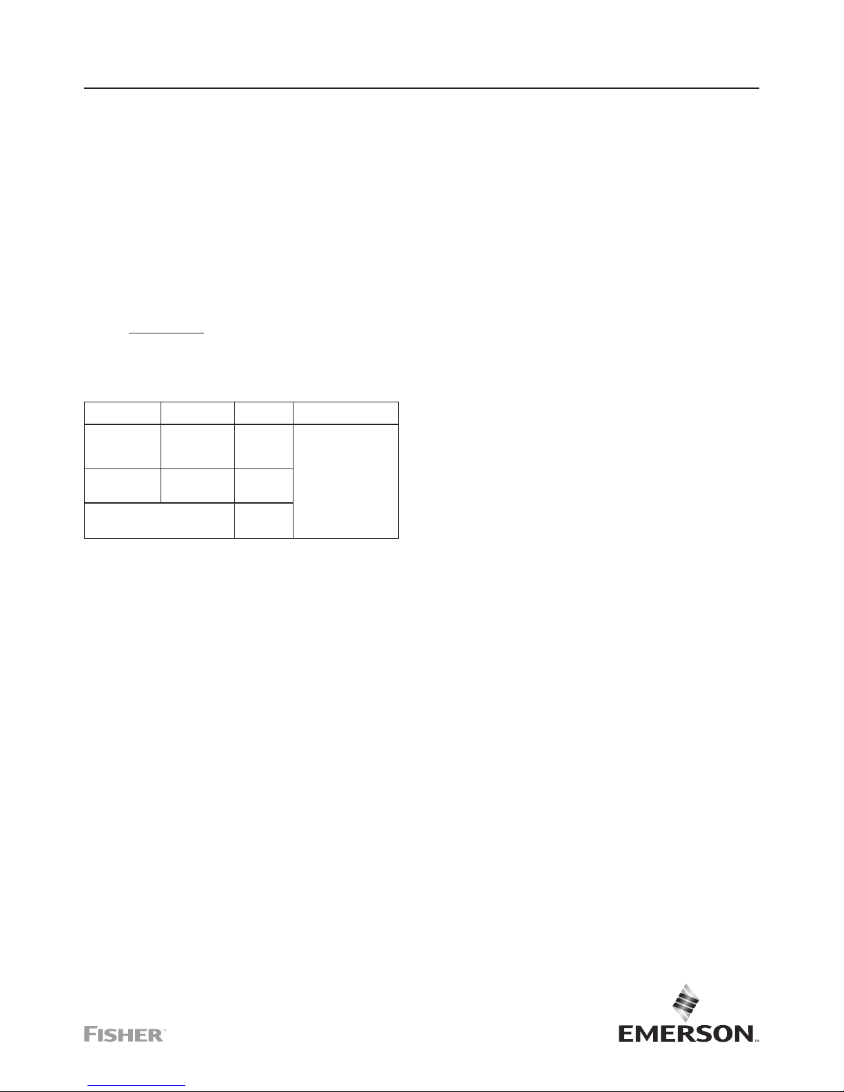
TYPE DESCRIPTION
PED
CATEGORY
FLUID GROUP
CSB700, CSB700F,
CSB720,
CSB720F and
CSB750
Base regulator I
Groups 1 and 2 according
to PED 2014/68/EU,
1st and 2nd family gas
according to EN 437 or
other gases (compressed
air, nitrogen). The gas
must be non-corrosive,
clean (ltration on inlet side
necessary) and dry.
CSB704, CSB704F,
CSB724F CSB724
and CSB754
Regulator with
Slam-shut Module
IV
European EN
Reference Standards
EN334 and
EN14382
Specifications
Available Configurations
See Table 1
Regulator Type
Differential Strength (DS)
Accuracy Class
Up to AC5 (depending on Outlet Pressure)
Lockup Class
Up to SG10 (depending on Outlet Pressure)
Failure Mode per EN334
Fail Open (FO)
Integral Strength (IS) Pressure Ratings
(1)
See Table 2
Differential Strength (DS) Pressure Ratings
(1)
See Table 3
Body Sizes, Materials, End Connections and
Pressure Ratings
(1)
See Table 4
Operating Pressure Range
(1)
Regulator: See Table 5
Slam-Shut Module: See Tables 7a, 7b, 7c and 7d
Maximum Outlet Pressure
(1)
Emergency Casing:
Type CSB700/CSB700F/CSB720/CSB720F:
4.0 bar / 58.0 psig
Type CSB750: 5.0 bar / 72.5 psig
To Avoid Internal Metallic Parts Damage:
Type CSB700/CSB700F/CSB720/CSB720F:
0.34 bar / 5.0 psig over set pressure
Type CSB750: 1.5 bar / 21.8 psig over set pressure —
not to exceed maximum emergency outlet
Operating Casing:
Type CSB700/CSB720: 1.1 bar / 16.2 psig
Type CSB750: 5.0 bar / 72.5 psig
Outlet Pressure Ranges
(1)
9.0 mbar to 4.0 bar / 0.13 to 58.0 psig
See Table 5
Orifice Size:
35 mm / 1-3/8 in.
Pressure Registration
External
Temperature Capabilities
(1)(2)(3)
According to PED Standards:
-20 to 66°C / -4 to 151°F
Non-PED:
-30 to 66°C / -22 to 151°F
Spring Case Vent Connection
1 NPT: Types CSB700 and CSB720
1/2 NPT: Type CSB750
Type VSX8 Slam-Shut Device Maximum Inlet
Pressure (P
umax
)
(1)
:
Differential Strength (DS): 16 bar / 232 psig
Integral Strength (IS): 6.0 bar / 87 psig
Approximate Weights
with Threaded body
Type CSB700/CSB720: 13 kg / 29 lbs
Type CSB750 : 14 kg / 31 lbs
Type CSB704/CSB724: 14 kg / 31 lbs
Type CSB754 : 15 kg / 33 lbs
with Flanged body
Add 5.2 kg / 11 lbs to weights listed
Designed, Tested and Evaluated Consistent With:
ANSI B16, ASME BPVC Sec. VIII Div. I, ASTM B117
(Corrosion Resistance), EN334 and EN14382
Directive ATEX Information
See Table 6
For information about ATEX, refer to CSB700 Series
(D103483X012) and VSX4/VSX8 Series
(D103127X012) Instruction Manuals.
1. The pressure/temperature limits in this Installation Guide or any applicable standard limitation should not be exceeded.
2. Standard token relief set values listed in Table 6 are based on -20 to 60°C / -4 to 140°F.
3. Product has passed Emerson Process Management Regulator Technologies, Inc. (Emerson) testing for lockup, relief start-to-discharge and reseal down to -40°.
CSB700 Series
2
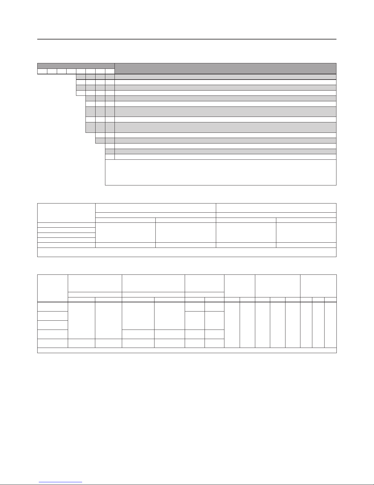
Table 1. Available Congurations
Table 2. Integral Strength (IS) Pressure Ratings
(1)
Table 3. Differential Strength (DS) Pressure Ratings and Flow and Sizing Coefcients
TYPE NUMBER
OPTION
C S B 7
PRESSURE CONSTRUCTION
0 Low Pressure Applications (Outlet Pressure: 9 to 110 mbar / 3.6 in. w.c. to 1.60 psig)
(2)
2 Medium Pressure Applications (Outlet Pressure: 61 to 780 mbar / 0.9 to 11.3 psig)
(2)
5 High Pressure Applications (Outlet Pressure: 0.7 to 4 bar / 10.2 to 58 psig)
(2)
OVERPRESSURE PROTECTION
0 Without Overpressure Protection Module
0F
Without Overpressure Protection Module (Outlet Pressure: 9 to 110 mbar / 3.6 in. w.c. to 1.60 psig and 270 to 325 mbar /
3.9 to 4.7 psig only)
(2)
4 With Type VSX8 Slam-shut Module
(1)
4F
With Type VSX8 Slam-shut Module
(1)
(Outlet Pressure: 9 to 110 mbar / 3.6 in. w.c. to 1.60 psig and 270 to 325 mbar /
3.9 to 4.7 psig only)
(2
PRESSURE REGISTRATION
E External
RELIEF
N None
T Token Internal Relief
(3)
Example: Type number CSB724ET: Type CSB700 regulator constructed for medium pressure applications, with Type VSX8 Slam-shut Module, with
External pressure registration and with Token relief.
1. Reference Instruction Manual D103127X012 for information regarding the Type VSX8 Slam-shut Module.
2. The pressure/temperature limits in this Installation Guide and any applicable standard or code limitation should not be exceeded.
3. Token relief not available for outlet pressure above 500 mbar / 8 psig.
TYPE
MAXIMUM ALLOWABLE PRESSURE /
MAXIMUM EMERGENCY INLET PRESSURE
MAXIMUM OPERATING INLET PRESSURE
(2)
P
S
P
UMAX
bar psig bar psig
CSB700 and CSB704
4.0 58.0 4.0 58.0
CSB700F and CSB704F
CSB720 and CSB724
CSB720F and CSB724F
CSB750 and CSB754 5.0 72.5 5.0 72.5
1. Applicable only to applications where the inlet rating cannot exceed the outlet rating.
2. For the Integral Strength (IS version), the maximum value of P
s
and P
umax
should be similar to the PSD used for the Differential Strength (DS) version.
TYPE
SPECIFIC MAXIMUM
ALLOWABLE PRESSURE /
MAXIMUM EMERGENCY
OUTLET PRESSURE
MAXIMUM ALLOWABLE PRESSURE /
MAXIMUM EMERGENCY INLET
PRESSURE
MAXIMUM
OPERATING INLET
PRESSURE
ORIFICE SIZE
WIDE-OPEN FLOW
COEFFICIENT
IEC SIZING
COEFFICIENT
P
SD
P
S
P
UMAX
bar psig bar psig bar psig mm In. C
g
C
v
C1XTFDF
L
CSB700 and
CSB704
4.0 58.0
12.0 174
10 145
35 1-3/8 1080 27.7 39 0.96 0.89 0.66
CSB700F and
CSB704F
6 87
CSB720F and
CSB724F
CSB720 and
CSB724
20.0 290 16 232
CSB750 and
CSB754
5.0 72.5 20.0 290 16 232
1. The pressure/temperature limits in this Instruction Manual and any applicable standard or code limitation should not be exceeded.
CSB700 Series
3
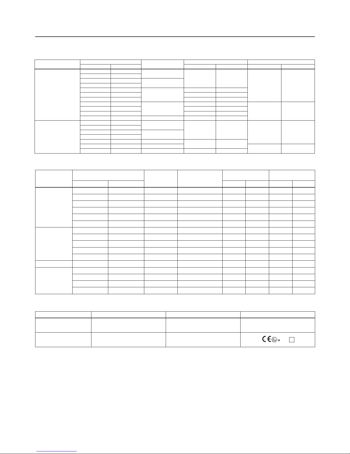
Table 4. Body Sizes, Material, End Connections and Cold Working Pressure Ratings
BODY MATERIAL
BODY SIZE
END CONNECTION
FACE-TO-FACE DIMENSION BODY PRESSURE RATING
DN NPS mm In. bar psig
Ductile Iron
40 1-1/2
NPT
155 6.10
17.2 250
50 2
40 1-1/2
Rp
50 2
50 2
CL125 FF/CL150 FF
191 7.52
50 2 254 10.0
50 2 267 10.5
50 2
PN 10/16
191 7.52
16.0 232
50 2 200 7.87
50 2 254 10.0
40 1-1/2 PN 16 Slip-On 222 8.74
WCC Steel
40 1-1/2
NPT
155 6.10
20.0 290
50 2
40 1-1/2
Rp
50 2
50 2 CL150 RF
254 20.0
50 2 PN 10/16
16.0 232
50 2 PN 10/16 191 7.52
Table 6. Directive ATEX Information
TYPE CLASSIFICATION ATEX ASSEMBLIES ATEX LABELLING
CSB704, CSB704F,CSB724,
CSB724, CSB724F, CSB754
version with VSX8
Non-electrical equipment Not falling under the ATEX Directive 2014/34/EU No
CSB704, CSB704F, CSB724,
CSB724, CSB724F and CSB754
with limit switch
Non-electric equipment equipped with an
electrical device falling under the scope of the
ATEX Directive 2014/34/EU
Constitutes an assembly according to the
ATEX Directive 2014/34/EU
2 G T
Table 5. CSB700 Series Primary Regulator Outlet Pressure Ranges
TYPE
OPERATING PRESSURE RANGES, W
d
PART NUMBER
SPRING
COLOR
SPRING WIRE
DIAMETER
SPRING FREE LENGTH
mbar psig mm In. mm In.
CSB700, CSB704,
CSB700F and CSB704F
9 to 14 3.6 to 5.6 in. w.c. GE30336X012 Silver 3.00 0.118 224 8.82
13 to 24 5.2 to 9.6 in. w.c. ERSA01138A0 Red 3.50 0.138 264 10.4
22 to 39 8.8 to 15.7 in. w.c. GE30338X012 Black Stripe 4.32 0.170 172 6.78
32 to 50 12.8 to 20.1 in. w.c. GE30339X012 Purple 4.34 0.171 187 7.35
42 to 70 16.9 to 28.1 in. w.c. GE30340X012 White Stripe 4.62 0.182 188 7.40
61 to 110 0.9 to 1.6 ERSA03656A0 Dark Green 4.88 0.192 224 8.82
CSB720 and CSB724
61 to 110 0.9 to 1.6 ERSA03656A0 Dark Green 4.88 0.192 224 8.82
105 to 220 1.5 to 3.2 ERSA03657A0 Blue 5.94 0.234 217 8.53
210 to 380 3.1 to 5.5 GG06247X012 Black 8.00 0.315 206 8.13
320 to 570 4.6 to 8.3 ERSA01582A0 Red with White Stripe 8.71 0.343 177 6.97
510 to 780 7.4 to 11.3 ERSA05055A0 Blue with White Stripe 10 0.394 181 7.13
CSB720F and CSB724F 270 to 325 3.9 to 4.7 ERAA11747A0 Black with White Stripe 6.5 0.256 235 9.25
CSB750 and CSB754
0.7 to 1.19 bar 10.2 to 17.3 GE30345X012 Purple Stripe 9.00 0.354 225 8.87
1.05 to 2.7 bar 15.2 to 39.2 GE30346X012 Brown 11.0 0.433 226 8.88
2.3 to 3.25 bar 33.4 to 47.1 ERSA01125A0 Grey with Red Stripe 12.6 0.496 225 8.87
3.1 to 4 bar 45 to 58 ERSA01126A0 Grey with Orange Stripe 13.7 0.539 226 8.89
CSB700 Series
4
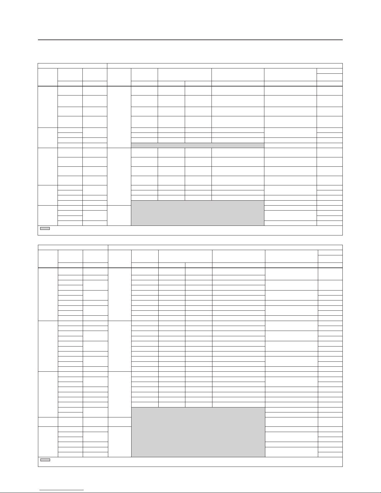
Table 7b. European Overpressure Shut-off OPSO Only Ranges
REGULATOR SLAM SHUT DEVICE
Type
Typical
Setpoint
Spring
Range
Type
(Maximum
Operating
Inlet)
Token
Relief Set
Relief Range Shown as a %
of Regulator Setpoint
Required Difference Between
Token Relief and OPSO
Over Pressure Shut-off
(OPSO) Set Range
Factory Set
OPSO
mbar mbar mbar min max mbar mbar mbar
CSB704F
10 9 to 14
VSX8L
(8.6 bar)
17 170 215 8
30 to 60 32
15 13 to 24 26 170 215 6
20
13 to 24
34 170 215 6
30 to 60 40
21 36 170 215 4
27
22 to 39
41 150 160 5
30 to 60
46
30 45 150 160 10 60
35 22 to 39 53 150 160 10 40 to 110 70
50
42 to 70
70 140 158 16
60 to 193
90
60 84 140 158 16 105
75 61 to 110 98 130 140 20 60 to 193 130
CSB704
10 9 to 14
VSX8L
(16 bar)
17 170 215 8
30 to 60
40
15 13 to 24 26 170 215 10 50
20
13 to 24
34 170 215 10
30 to 60
55
21 36 170 215 10 55
27
22 to 39
41 150 160 10
30 to 60
55
30 45 150 160 10 60
35 22 to 39 53 150 160 10 40 to 110 70
50
42 to 70
70 140 158 16
60 to 193
90
60 84 140 158 16 105
75 61 to 110 98 130 140 20 60 to 193 130
CSB724
100 61 to 110
VSX8L
(16 bar)
130 130 140 20 60 to 193 170
120
105 to 220
156 130 140 40
95 to 280
205
150 195 130 140 40 250
160 105 to 220 208 130 140 40 95 to 280 265
200 105 to 220 250 125 140 50 138 to 500 330
300 210 to 380 375 125 140 50 138 to 500 450
500 320 to 570 625 125 140 60 221 to 760 700
600
510 to 780
400 to 915
(1)
840
750 400 to 1100
(1)
1050
CSB724F 300 270 to 325
VSX8L
(8.6 bar)
138 to 500 450
CSB754
1000 700 to 1190
VSX8H
(16 bar)
400 to 1450 1320
1200
1050 to 2700 900 to 3000
1600
1500 1900
2000 1050 to 2700 1600 to 4000
(1)
2400
3000 2300 to 3250
1600 to 5000
(1)
3400
4000 3100 to 4000 4400
- Gray areas indicate that token relief is not available above 500 mbar setpoint.
1. Max OPSO setpoint truncated to reect maximum outlet pressure for spring range.
Table 7a. North American Overpressure Shut-off OPSO Only Ranges
REGULATOR SLAM SHUT DEVICE
Type
Typical
Setpoint
Spring
Range
Type
(Maximum
Operating
Inlet)
Token
Relief Set
Relief Range Shown as a %
of Regulator Setpoint
Required Difference Between
Token Relief and OPSO
Over Pressure Shut-off
(OPSO) Set Range
Factory Set
OPSO
psig psig psig min max psig psig psig
CSB704F
7 in. w.c.
5.2 to
9.6 in. w.c.
VSX8L
(125 psi)
12 in. w.c. 170 215 3.2 in. w.c. 12 to 24 in. w.c. 22 in. w.c.
11 in. w.c.
8.8 to
15.7 in. w.c.
17 in. w.c. 150 160 4 in. w.c. 16 in. w.c. to 1.6 psig 25 in. w.c.
14 in. w.c.
12.8 to
20.0 in. w.c.
21 in. w.c. 150 160 4 in. w.c. 24 in. w.c. to 2.8 psig 1.1
1
24 in. w.c. to
1.6 psig
1.4 140 150 6.4 in. w.c. 1.4 to 4.1 2
CSB724F
2
1.5 to 3.2
2.6 130 140 0.6
2.0 to 7.3
3.5
3 3.8 125 140 0.6 5
5 3.1 to 5.5 6.2 125 140 0.7 3.2 to 11.0 7
10 7.4 to 11.3 5.8 to 13.3
(1)
12
CSB704
7 in. w.c.
5.2 to
9.6 in. w.c.
VSX8L
(232 psi)
12 in. w.c. 170 215 3.2 in. w.c. 12 to 24 in. w.c. 22 in. w.c.
11 in. w.c.
8.8 to
15.7 in. w.c.
17 in. w.c. 150 160 4 in. w.c. 16 in. w.c. to 1.6 psig 25 in. w.c.
14 in. w.c.
12.8 to
20.0 in. w.c.
21 in. w.c. 150 160 4 in. w.c. 24 in. w.c. to 2.8 psig 1.1
1
24 in. w.c. to
1.6 psig
1.4 140 150 6.4 in. w.c. 1.4 to 4.1 2
CSB724
2
1.5 to 3.2
2.6 130 140 0.6
2.0 to 7.3
3.5
3 3.8 125 140 0.6 5
5 3.1 to 5.5 6.2 125 140 0.7 3.2 to 11.0 7
10 7.4 to 11.3 5.8 to 13.3
(1)
12
CSB754
15 10.2 to 17.3
VSX8H
(232 psi)
13.1 to 39.1
(1)
19
20
15.2 to 39.2 13.1 to 43.5
25
30 35
40 33.4 to 47.1 23.2 to 72.5
(1)
45
- Gray areas indicate that token relief is not available above 8 psig setpoint.
1. Max OPSO setpoint truncated to reect maximum outlet pressure for spring range.
 Loading...