

Emerson CROSBY STYLE HC ISOFLEX, CROSBY STYLE HCA ISOFLEX Installation, Maintenance And Adjustment Instructions
Page 1

CROSBY® STYLES HC AND HCA ISOFLEX™ SAFETY VALVES
INSTALLATION, MAINTENANCE AND ADJUSTMENT INSTRUCTIONS
Before installation these instructions must be read fully and understood
TABLE OF CONTENTS
1. Style HC/HCA ISOFLEX - parts ..................... 2
2. Introduction ................................................... 3
3. Description of safety valve ............................ 4
4. Storage ........................................................... 4
5. Installation ..................................................... 5
6. Hydrostatic testing ........................................ 6
7. Operation ....................................................... 9
8. Testing.......................................................... 10
9. Valve maintenance ...................................... 12
General information .................................... 12
Disassembly ................................................ 12
Repair procedure ........................................ 14
10. Valve assembly ............................................ 16
11. Spare parts .................................................. 18
12. Field service requirements ......................... 19
13. Maintenance equipment ............................. 19
Safety precautions
Proper handling, storage, installation,
maintenance and operation is essential to the
safe and reliable functioning of any pressure
relief product.
Precautionary statements in the form of
warnings, cautions and notes are used
throughout this instruction to emphasize
important and critical factors where applicable.
Examples:
WARNING
An operating procedure or practice which, if not
observed strictly, may result in injury to personnel
or loss of life.
CAUTION
An operating procedure or practice which, if not
observed strictly, may result in damage to or
destruction of equipment.
NOTE
An operating procedure or condition which is
highlighted, underlined or printed in bold type for
emphasis.
These precautionary statements are by no means
exhaustive. Emerson cannot be expected to know,
evaluate and advise customers of all conceivable ways
in which tasks might be performed, or of the possible
hazardous consequences of each way.
Consequently, Emerson has not included
such comprehensive evaluation and disclaims
liability for work performed by other than
Emerson personnel. All personnel working with
Crosby products should be trained adequately
and be thoroughly familiar with the contents of
this manual.
Emerson cannot evaluate all conditions that
might injure personnel or damage equipment.
However, Emerson does offer the following
general safety precautions:
• Hearing and eye protection should be used
when working on a valve which is under
pressure.
• Never strike a valve which is under pressure.
Premature actuation can result.
• Never stand in front of the discharge outlet
of a pressure relief valve which is under
pressure.
Always approach and use any pressure relief
valvewith great care.
Often, the safety of lives and property
depends on the proper operation of the
safety valves. Consequently, the valves
should be kept clean and should be tested
periodically and reconditioned to make sure
theyfunctionproperly.
WARNING
Suitability of the material and product for
the use contemplated by the buyer is the
sole responsibility of the buyer. Also storage,
installation and proper use and application are
the sole responsibility of the purchaser. Emerson
disclaims any and all liability arising out of same.
Any installation, maintenance, adjustment,
repair and testing performed on safety relief
valves should be done in accordance with
the requirements of all applicable codes and
standards under which those performing such
work should maintain proper authorization
through appropriate governing authorities. No
repair, assembly and test work done by other
than Emerson shall be covered by the warranty
extended by Emerson to its customers.You
assume full responsibility for your work. In
maintaining and repairing Crosby products, you
should use only parts manufactured by Emerson.
Call your nearest Emerson sales office or our
factory for a service engineer should you wish
assistance with your field needs.
Engineering Doc. #IS-V3147A
Emerson.com/FinalControl © 2017 Emerson. All Rights Reserved. VCIOM-06201-EN17/05
Page 2
CROSBY® STYLES HC AND HCA ISOFLEX™ SAFETY VALVES
INSTALLATION, MAINTENANCE AND ADJUSTMENT INSTRUCTIONS
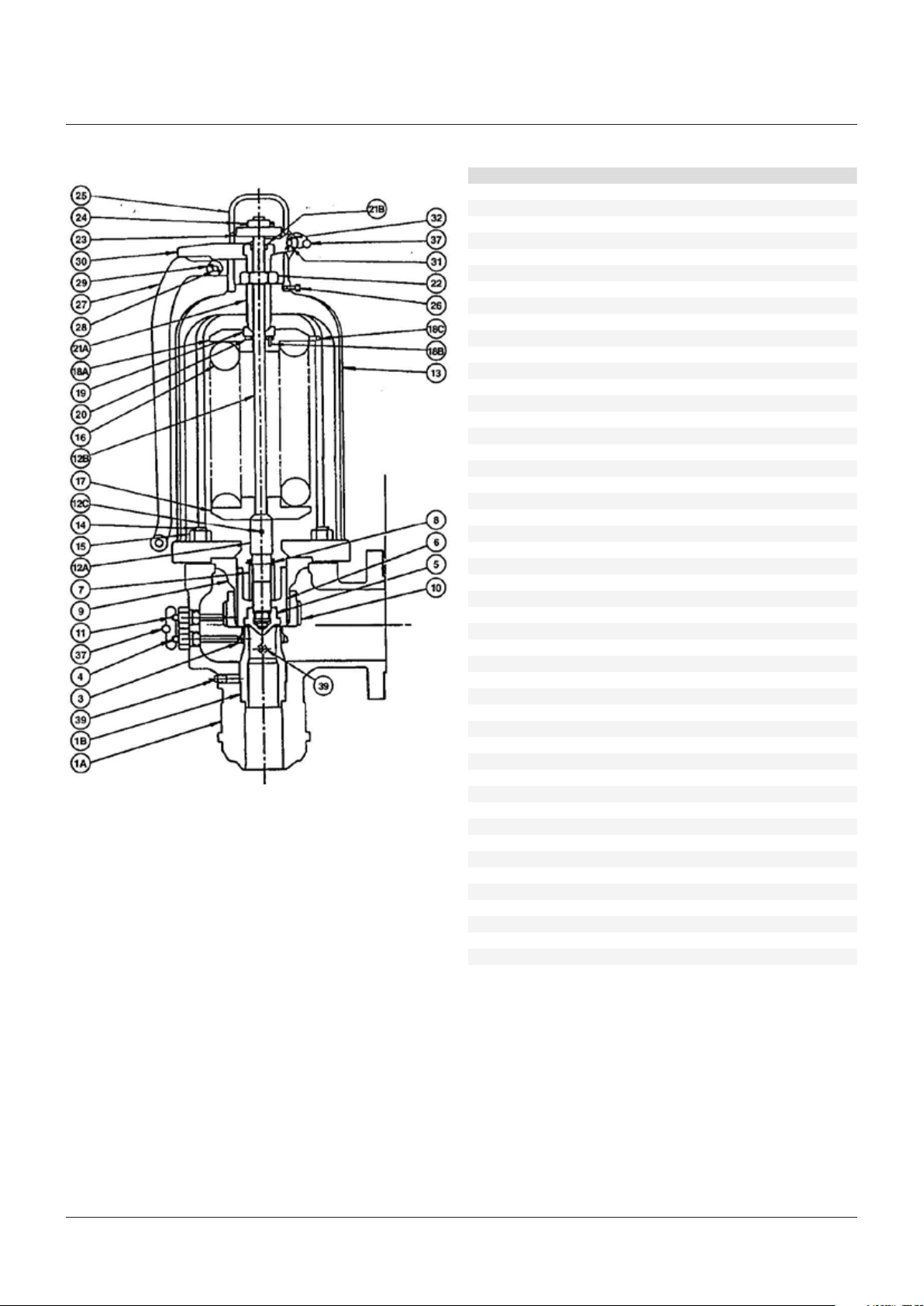
FIGURE 1 - STYLE HC ISOFLEX SAFETY VALVE
PARTS LIST
Part Part name Spare parts*
1A Body
1B Nozzle
3 Nozzle ring 3
4 Nozzle ring set screw
5 Disc insert 1
6 Disc holder 2
7 Disc holder retaining nut
8 Disc holder retaining cotter 1
9 Guide 3
10 Guide ring 3
11 Guide ring set screw
12A Spindle point 3
12B Spindle rod 3
12C Spindle rod pin 3
13 Bonnet
14 Bonnet stud
15 Bonnet stud nut
16 Spring 3
17 Bottom spring washer 3
18A Top spring washer 3
18B Bearing pin 3
18C Locking pin 3
19 Bearing adapter
20 Bearing
21A Adjusting bolt
21B Adjusting bolt bearing
22 Adjusting bolt nut
23 Spindle nut
24 Spindle nut cotter 1
25 Cap
26 Cap set screw
27 Lever
28 Lever pin
29 Lever pin cotter 1
30 Forked lever
31 Forked lever pin
32 Forked lever pin cotter 1
34 Test clamp
36 Test rod
37 Seal and wire
38 Protective hood
39 Drain plug
40 Hydro test plug assembly
41 Nameplate
42 Drive screw
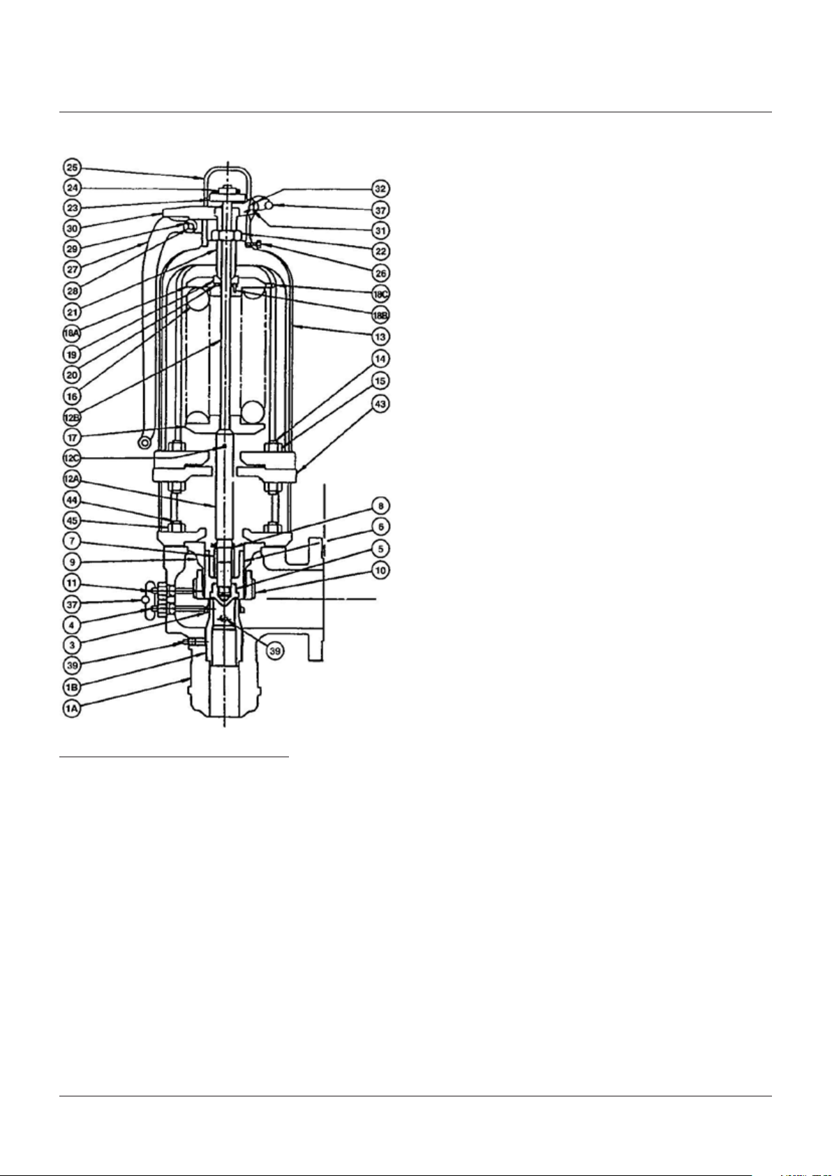
43** Cooling spool
44** Cooling spool stud
45** Cooling spool stud nut
NOTES
* Spare parts designation (see notes 1, 2, 3 in Section 2)
** For Crosby Style HCA ISOFLEX only
2
Page 3
CROSBY® STYLES HC AND HCA ISOFLEX™ SAFETY VALVES
INSTALLATION, MAINTENANCE AND ADJUSTMENT INSTRUCTIONS
FIGURE 2 - STYLE HCA ISOFLEX SAFETY VALVE
2 INTRODUCTION
Crosby Style HC and HCA ISOFLEX safety
valves have been selected because of their
performance features, reliability and ease
ofmaintenance.
This manual contains information on
installation, hydrostatic testing, field testing
and adjustments and maintenance of these
valves. It is specific to the Isoflex design K
through M
orifice sizes. Adherence to the
2
installation and maintenance procedures
specified in this manual will provide the utmost
in safety, a minimum of maintenance and a
long service life.
Style HC is a high capacity reaction type safety
valve designed for saturated and superheated
steam applications to temperatures of 750°F.
Crosby Style HCA is a high temperature
version of the Style HC, with an alloy steel
construction suitable to temperatures
upto1020°F. TypicallyStyle HCA valves are
used for superheaters and reheater outlets.
DetailsofStyle HC and HCA safety valves,
materials of construction, sizes, pressuretemperature ratings, dimensions, weights and
certified capacities are available on request.
No special tools are necessary for the
maintenance of Style HC and HCA safetyvalves.
However, tools and equipment are available
to ease disassembly and on site testing of
the valves. Such tools and equipment include
the hydraulic set pressure device, the air
set pressure device (see Figure 15) and the
hydraulic jacking device (see Figure 14).
Detailed instructions on their use can be found
in instructions I-11288, T-1652 and I-1167
respectively.
Whenever Style HC/HCA safety valve parts
names are used in this manual, parts numbers
in parenthesis follow. The parts numbers are
an aid to identifying the parts in Figures 1 and 2
and the correlating parts list.
NOTES
1. Consumable spare parts: valve parts which should
be replaced as part of any disassembly, and discs
and disc inserts which must be replaced if seats
are damaged.
2. Repair spare parts: valve parts exposed to wear
and/or corrosion during normal operation.
They are in fluid flow paths and may require
replacement as part of any repair.
3. Insurance spare parts: valve parts exposed to
process or environmental wear and/or corrosion
and may require replacement as part of a
majorrepair.
Emerson recommends that sufficient inventory
of spare parts be maintained to support process
requirements. Always be sure to use genuine
Emerson parts to ensure continued product
performance and warranty.
3
Page 4
CROSBY® STYLES HC AND HCA ISOFLEX™ SAFETY VALVES
INSTALLATION, MAINTENANCE AND ADJUSTMENT INSTRUCTIONS
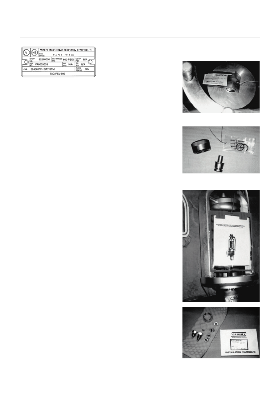
Crosby Style HC/HCA ISOFLEX nameplate
(With sample information for illustrative
purposes only)
Ordering spare parts
When ordering spare parts, the valve size,
style and shop number and/or serial number
should be given together with set pressure,
part name and reference number. The valve
assembly number is shown on the valve
nameplate as 'Shop number'. Spare parts may
be ordered from any Emerson sales office
orrepresentative.
3 DESCRIPTION OF SAFETY VALVES
Crosby Style HC/HCA safety valves are shown
in Figures 1 and 2. These drawings illustrate
the safety valves assembled in cross-section,
and cover the essential elements of the valves.
Approved drawings supplied with the valves
should be used when installation and/or
specific information is required.
Inside the body (1A) is housed the upper portion
of the nozzle (1B), nozzle ring (3), and the
guide ring (10). The disc insert (5) is held in
place in the disc holder (6) by the spindle and
disc holder retainer nut (7). The nozzle ring
and adjusting rings are held in place by the
nozzle ring set screw (4) and the guide ring set
screw(11), which are threaded into the body.
The guide (9) is retained between the body (1A)
and the bonnet (13) by the bonnet studs (14)
and the bonnet studs nuts (15). In the case of
Style HCA valves, a cooling spool (43) is placed
between the body and bonnet to protect the
spring from exposure to extreme temperatures.
The bonnet (13) contains the spring (16),
spring washers (17 and 18) and the spindle
assembly(12). The spindle point is held in
compression between the back face of the disc
insert (5) and the bottom spring washer. The
spring is compressed between the stationary
point of contact with the spindle and the
adjusting bolt (21A) atop the valve bonnet.
The adjusting bolt (21A) is locked in place by the
adjusting bolt nut (22) on top of the bonnet and
within the cap assembly. A means of manual
lifting is provided by the lever (27), lever pin (28),
forked lever (30), forked lever pin (31) and the
spindle nut (23).
4 STORAGE
Often, safety valves are on the job site
months before they are installed. Unless
they are stored properly and protected, their
performance may be affected seriously.
Rough handling may damage flanges or cause
misalignment of the parts. It is best to leave the
safety valves in their shipment cases and store
them in a dry place under cover until they are
tobe installed.
FIGURE 3 - VALVE BODY AS SHIPPED
TOP VIEW - BODY
HYDRO COMPONENTS (see note 1, page 5)
FIGURE 4 - VALVE SUPERSTRUCTURE AS
SHIPPED
4
Page 5

CROSBY® STYLES HC AND HCA ISOFLEX™ SAFETY VALVES
INSTALLATION, MAINTENANCE AND ADJUSTMENT INSTRUCTIONS
Factory preparation of welded inlet valves
forshipment
All Crosby Style HC and HCA welded inlet safety
valves are equipped with hydrostatic test plugs
and shipped in two parts: valve body and valve
superstructure. This makes handling easier for
installation welding (seeFigures3and 4).
The welded inlet Style HC and HCA safety
valves are specially prepared for shipment
fromthe factory.
After the safety valve is tested as a complete
assembly for set pressure and tightness, the
spring set compression is held by spacer
blocks under the bottom spring washer as
illustrated in Figure 4.
The safety valve superstructure is then
removed from the valve body. The two portions
are boxed and shipped separately. Each portion,
ready for shipment, is illustrated in Figures 3
and 4.
Figure 3 shows the safety valve body as shipped
to the installation site. It is tagged as follows:
• Install and/or weld in place as required
• Prepare for hydrostatic test. See instruction
Hydrostatic plug in place
• Install O-ring and backup ring prior to
hydrostatic test.
Figure 4 shows the safety valve superstructure
as shipped to the installation site. It is boxed
separately from the valve body and is tagged
asfollows:
• Hold for assembly after hydrostatic test.
5 INSTALLATION
Inlet piping
Many safety valves are damaged when first
placed in service because of failure to clean
the connections properly before installation.
The safety valve inlet, the vessel and the line
on which the safety valve is mounted must be
cleaned thoroughly of all foreign matter.
Safety valves should be mounted in a vertical
position, directly on the pressure vessel.
The ASME boiler and pressure vessel code limits
the distance between the safety valve inlet and
the boiler to the length of a standard tee fitting.
The nozzle should have a well-rounded
approach that provides smooth, unobstructed
flow between the vessel and the safety valve.
A safety valve should never be installed on a
fitting having an inside diameter smaller than
the inlet connection of the valve.
Such restriction of flow can cause faulty
valveoperation.
Inlet piping (nozzles) must be designed to
withstand the total resultant forces due to
the safety valve discharging at the maximum
accumulated pressure and the expected
piping loads. The precise nature of the loading
and the resulting stresses will depend on
the configuration of the safety valve and the
discharge piping. Determination of outlet
reaction forces is the responsibility of the
designer of the vessel and/or piping.
Welding of welded inlet valve body to boiler
Welded inlet safety valve bodies should be
welded to the boiler in accordance with
applicable Code requirements. The protective
cover (Figure 3) should be left in place until
ready for the hydrostatic test of the unit.
If visual inspection is necessary, the protective
cover may be removed, but should be replaced.
NOTES
Note 1 to Figure 3
Delivered with the body and packaged in small
bag are the following:
• One O-ring (for hydrostatic test)
• One backup ring (for hydrostatic test)
• One hydrostatic test plug pin
Note 2 to Figure 4
Delivered with the superstructure and
packaged in a small box are the following:
• Valve nozzle ring*
• Valve nozzle ring set screw*
• Valve guide ring set screw*
• Seal wires
* Marked with valve identification number.
NOTE
When the above parts are removed from their boxes,
be sure that the identification of parts to valve number
is maintained and that the parts are stored to facilitate
later recovery for assembly.
Outlet piping
Discharge piping should be simple and
direct. Back pressures built up by discharge
flow affect the operation of safety valves.
Where possible, a short vertical pipe connected
through a long radius elbow discharging
directly into the atmosphere is the most
desirable type of outlet piping.
Discharge piping should not impose any loading
on the safety valve. Excessive discharge piping
loads may cause seat leakage or faulty valve
operation. The inside diameter of the discharge
pipe must never be less than that of the safety
valve outlet.
Valve effluent must discharge to a safe
disposalarea.
Safety valve bodies have pipe thread openings
for drains. These should be connected to
prevent any accumulation of fluid in the valve
body. In addition, discharge piping also should
be drained to prevent any accumulation of fluid.
Care must be taken to ensure that the drains
are directed or piped to a safe disposal area.
5
Page 6

CROSBY® STYLES HC AND HCA ISOFLEX™ SAFETY VALVES
INSTALLATION, MAINTENANCE AND ADJUSTMENT INSTRUCTIONS
6 HYDROSTATIC TESTING
General information
Depending on the type of inlet, hydrostatic
testing of safety valves may be carried out by
one of three means: blank flanges, test plugs or
test gags. In all cases, hydrostatic test pressure
must be limited to 1½ times the nameplate set
pressure of the valve.
CAUTION
Additionally, hydrostatic test pressure must be
limited to 10% above nameplate set pressure
when a test gag is used.
Welded inlet safety valves
All Style HC/HCA welded inlet safety valves are
prepared for shipment from the factory with
hydrostatic test plugs, as detailed in Section 4 paragraph 'Factory preparation of welded inlet
valves for shipment' and Figure 3.
Hydrostatic tests of these valves shall be
conducted using hydrostatic test plugs as
detailed in paragraph below 'Hydrostatic
testing using hydrostatic test plugs'.
Flanged inlet safety valves
Flanged inlet safety valves should not be
installed for hydrostatic testing. Blank flanges
should be used instead of gagging the safety
valves. This prevents possible damage to the
safety valves due to excessive tightening of
the gag screws or leakage during hydrostatic
test which may result in costly repairs.
Blank flanges must be removed and the
safety valve reinstalled before the vessel
isplacedinservice.
If blank flanges are not used and the safety
valves are to be installed for hydrostatic
tests, Emerson recommends that hydrostatic
test plugs be used for hydrostatic test.
The detailed procedure is outlined in the
paragraph following. Hydrostatic test plugs for
flanged valves are optional equipment and are
providedonly when ordered.
Remove the protective cover from the valve
body. Unscrew the cap from the nozzle.
Remove the test plug from the nozzle bore.
• Preparation for hydrostatic testing Flanged inlet safety valves
Flanged inlet safety valves are shipped
from the factory fully assembled. To use
the hydrostatic test plug, the valve must
be disassembled according to Section 9 paragraph 'Disassembly retaining spring
compression'.
• Installation of hydrostatic test plug
(seeFigure 3)
Inspect the hydrostatic test plug O-ring
groove.
Note: make sure the groove in the plug
isclean.
Install the O-ring and backup ring in the
testplug groove.
CAUTION
Be sure the test plug is seated on the 45°
angleonthe nozzle inside diameter.
Replace the test plug in the nozzle bore.
Place the test plug cap over the plug and
screwit down hand-tight.
CAUTION
Make sure the cap has hand-tight contact with
the plug. Make sure there is enough thread
engagement of the cap onto the nozzle.
Install the test plug pin.
The valve is now ready for hydrostatic test.
• Hydrostatic test
After the above preparation, the safety valve
is ready for hydrostatic test. Observations
should be made at the start of the test to
confirm that the O-rings have been installed
properly and there is no leakage when
pressure is applied.
To aid removal, place the hydrostatic test
plug pin in the hole in the plug extension.
Unscrew the cap, which will engage the plug
pin and exert an upward force as the cap is
turned, thus lifting the plug. Remove from
thevalvenozzle.
Clean the nozzle bore and seat and inspect
the seating surface. If seating surfaces are
damaged, repair according to the directions
in Section 9 - paragraph 'Repair procedure'.
Assemble the valves according to the
instructions in Section 6 - paragraph
'Initialsafety valve assembly'.
Contact Emerson field service for service
equipment (see Section 12 - paragraph
'Service equipment available').
Hydrostatic testing using hydrostatic
testplugs
Before imposing the hydrostatic test pressure
on the vessel or system, perform the following
operations:
CAUTION
Before hydrostatic testing, the O-ring and backup
ring must be installed.
• Preparation for hydrostatic testing Weldedinlet safety valves
The O-ring, backup ring and the test plug
pin are shipped in a box attached to the
superstructure (see Figure 3). The contents
ofthe box are marked for identification.
To install the O-ring and backup ring refer
toFigure 3.
CAUTION
Tightening of the cap will not reduce leakage.
If leakage is evident, remove all pressure from
the vessel or system. Replace the O-ring and
thebackup ring.
WARNING
Do not try to assemble the valve or remove
the steel blocks from under the bottom spring
washerwithout use of proper servicing and
assembly equipment.
• Assembly of valve
After completion of the hydrostatic test,
remove the hydrostatic test plug from
thenozzle.
6
Page 7

CROSBY® STYLES HC AND HCA ISOFLEX™ SAFETY VALVES
INSTALLATION, MAINTENANCE AND ADJUSTMENT INSTRUCTIONS
NORMAL GAGGING LOAD in ft·lb OF TORQUE (Nm) VS. ΔP
ΔP
(Overpressure less valve set pressure)
psi(bar)
50 (3.45) 1 (1.4) 1 (1.4) 2 (2.7) 2 (2.7)
100 (6.89) 2 (2.7) 3 (4.1) 4 (5.4) 4 (5.4)
150 (10.34) 2 (2.7) 4 (5.4) 5 (6.8) 6 (8.1)
200 (13.79) 3 (4.1) 5 (6.8) 7 (9.5) 8 (10.8)
250 (17.24) 4 (5.4) 6 (8.1) 9 (12.2) 10 (13.6)
300 (20.68) 5 (6.8) 7 (9.5) 11 (14.9) 12 (16.3)
Hydrostatic test using gag
The safety valve test gag shown in Figure 5 can
be used with both welded and flanged inlets,
but at pressures no greater than 10% above the
nameplate set pressure.
Gagging should be done very carefully in
K K
• After applying the necessary torque to the
gags, increase the hydrostatic test pressure
to the required amount. Observations should
be made during the rising pressure cycle to
determine if any of the safety valves show
seat leakage.
2
Orifice
psi (bar)
M M
ordernot to overload the valve spindle or
causedamage to the valve seats.
The following outlines the recommended
procedure for gagging valves for
CAUTION
Should any safety valve show seat leakage, the
pressure must be lowered until the leakage stops.
hydrostatictest:
• The torque should then be increased on the
CAUTION
gag about 10% above the initial torque value.
Gags should not be used when inlet pressures are
more than 10% greater than the safety valve set
pressure. Damage to the valve may result.
CAUTION
Never increase the gagging load while a safety
valve shows seat leakage. This can result
• Remove the lever (27), forked lever (30),
cap(25) and spindle nut (23).
in damage to the valve seats and bending
ofthespindle.
• Refer to Figure 5. Lubricate the threads and
pointed end of the gag screw. Install the
gag in place, being careful that the legs fit
uniformly. Contacts on both legs of the gag
should seat evenly on the underside of the
bonnet top.
• After the hydrostatic test, the pressure on the
system should be dropped to approximately
100psi below the nameplate set pressure of
the safety valve. The gags should be loosened
at this point and removed from the valves.
• Tighten the gag finger-tight only at this point.
• Raise the system pressure to approximately
100psig below the nameplate set pressure
ofthe safety valve.
• Apply the necessary torque to the gag in
accordance with the value shown in the
CAUTION
Valve gags should not be left on the valves in
a gagged or loaded position for an extended
period or under conditions where large thermal
variations are expected.
tableabove for the specific orifice size. This
torque value is determined as follows:
- Determine Δ by subtracting the valve set
pressure from the hydrostatic test pressure.
• After the hydrostatic test, the gag should be
removed and the cap reinstalled according
toSection 10 - paragraph 'Assembly of cap'.
- Read the value of Δ on the vertical scale.
Proceed horizontally to the appropriate
orifice size and then down to read the
torqueon the horizontal scale.
- The torque values (foot-pounds) obtained
should be increased by a factor of
approximately 25% to account for normal
variations in friction, safety valves and
testconditions.
FIGURE 5 - VALVE GAG
POSITION GAG EVENLY ON BONNET
2
7
Page 8

CROSBY® STYLES HC AND HCA ISOFLEX™ SAFETY VALVES
INSTALLATION, MAINTENANCE AND ADJUSTMENT INSTRUCTIONS
Initial safety valve assembly
After hydrostatic testing using hydrostatic test
plugs, the safety valves should be assembled.
NOTE
It is recommended that, on completion of all
hydrostatic tests using hydrostatic test plugs on new
installations, a Emerson service technician be present
for assembly of the safetyvalves (see Section 12 'Field service requirements').
Check the valve identification numbers and
match the proper valve superstructure to each
valve body.
The nozzle ring (3) and the set screws (4 and11)
are packaged together and shipped with the
superstructure as shown in Figure 4.
CAUTION
Each valve superstructure, nozzle ring and set
screw is identified and matched to a specific valve
body by a tag number and should be assembled
accordingly. Although all parts have been cleaned
thoroughly, inspected, lubricated and protected
for shipment, the parts should be inspected
before installation for evidence of foreign matter
or damage. Special attention should be given
to the seating surfaces of the disc and nozzle.
These seats should be free from surface damage.
If cleaning or repair is necessary refer to
Section 9 - paragraph 'Repairprocedure'.
Initial assembly
Remove the body protective cover (see
Figure3).
Take the nozzle ring (3), nozzle ring set
screw(4) and guide ring set screw (11) from
their package (see Figure 4). Match the set
screws to the body (1A) and bonnet (13) valve
identification markings.
Screw the nozzle ring (3) onto the nozzle (1B).
NOTE
The top of the nozzle ring (3) should be about one ring
revolution above the nozzle (1B) seating surface.
Remove the guide (9) and guide ring (10)
from the superstructure. The guide ring
should be screwed onto the guide. Install
the guide and guide ring assembly into the
top of the body(1A). Make sure the guide is
seated correctly in the body. Make sure that
the nozzle(1B) and disc insert (5) seats are
clean and undamaged. If cleaning or repair
is necessary refer to Section 9 - paragraph
'Repair procedure'.
Remove the lever (27), forked lever (30) and
cap (25) from the valve superstructure. Do not
remove the spindle nut (23).
Using a suitable lifting device, lift the valve
superstructure with the spindle assembly(12)
vertical. Inspect and clean the guide-to-bonnet
fit and the body-to-guide fit. Position the
superstructure so the valve identification
number stamped on the bonnet (13) is
oppositethe valve outlet.
Lowering the valve superstructure slowly,
carefully lower the disc holder (6) into the
guide(9).
CAUTION
Do not permit any rocking motion of the
spindle(12) or any other part while lowering the
superstructure into the body (1A). Any rocking
motion could damage the valve seats.
After the superstructure in in place, inspect
tobe sure the bonnet (13) is fully seated on
theguide (9).
The nozzle ring (3) should now be lowered.
Lift the disc insert (5) slightly off the
seat by lifting the spindle assembly (12).
Place a screwdriver in the lower set screw hole.
Turn the nozzle ring to the left (clockwise) with
the screwdriver until the top edge of the nozzle
ring is below the nozzle (1B) seating surface.
The location can be checked by looking in
through the upper set screw hole while shining
a light through the lower set screw hole.
Lower the spindle assembly slowly until
it bottoms. Check that the nozzle ring
movesfreely.
Rotate the spindle clockwise several
revolutions to make sure that it is seated fully
on the disc insert and that the threads of the
spindle are not engaged.
The seating surfaces are now in full contact.
Install the bonnet stud nuts (15) on the bonnet
studs (14) and tighten uniformly in accordance
with Figure 6.
It is now necessary to remove the spacer blocks
under the bottom spring washer (17), thereby
transferring the spring load to the valve seats.
This should be done using the hydraulic jacking
device (see Figure 14). Refer to instruction
I-1167 for detailed instructions in the use of this
device.
After the spacer blocks have been removed, set
the nozzle ring (3) and guide ring (10) according
to Section 10 - paragraph 'Setting of rings'.
Lock the nozzle ring set screw (4) and the
guide ring set screw (11) in place, making sure
that the proper set screws are installed and
engaged fully in a notch. Lock wire them in
place and seal.
8
Page 9

CROSBY® STYLES HC AND HCA ISOFLEX™ SAFETY VALVES
INSTALLATION, MAINTENANCE AND ADJUSTMENT INSTRUCTIONS
Torque (ft·lb) (Nm) to produce stress in stud bolts
30.000psi (2.068bar) 45.000psi (3.203bar) 60.000psi (4.137bar)
Stress Stress Stress
Stud thread
⅝-11
¾-10
⅞-9
1-8
1⅛-8
Complete the valve assembly with the cap assembly as described in Section 10 - paragraph 'Assembly of cap'
and seal wire the cap set screws.
NOTES
1. Valve studs and nuts shall be clean and inspected
visually to ensure freedom from any objectionable
foreign matter, rust, burnsor physical damage.
2. With the bonnet in place, lubricate the bonnet
studs threads, the nut threads and nut face with
'Never-Seez' compound (which conforms to
Government specification MIL-A-907B, Federal
stock number 803-286-5453) or equivalent.
3. Install nuts on the studs finger-tight.
4. Tighten the nuts in the sequence shown in Figure
6 to approximately one-half the torque value
shown in the table. Repeat the same sequence
of tightening to the torque value shown. Then,
starting with the number 1 nut, tighten each nut in
order in a clockwise or counterclockwise direction
to the value shown in the table above.
5. Wipe off excess lubricant.
ft·lb (Nm) ft·lb (Nm) ft·lb (Nm)
60 (81) 90 (122) 120 (163)
100 (136) 150 (203) 200 (271)
160 (217) 240 (325) 320 (434)
240 (325) 370 (502) 500 (6-78)
350 (475) 525 (712) 700 (949)
The sharp opening is produced in two stages.
The initial lift is produced when the steam
pressure under the disc insert (5) exceeds
the spring pressure. To aid in starting the
popping action, steam escapes between the
safety valve seats and is deflected by an angle
on the nozzle ring (3) as shown in Figure 7.
This escaping steam acts on the face of the disc
holder (6) causing an unbalance and the safety
valve pops open. As the disc holder moves
vertically, steam begins to react against the
guide ring(10) and to push the disc holder up
to a high lift as shown in Figure 8. The reaction
of the deflected steam pushes against the
underside of the disc holder and lifts it still
higher on an accumulation of pressure.
As the boiler pressure drops, the safety valve
disc insert (5) settles to a moderate lift and
closes sharply.
7 OPERATION
The nozzle ring (3) is primarily for ensuring
sharp opening action. Raising the nozzle
Crosby Style HC/HCA safety valves open with a
sharp pop at the set pressure and remain open,
relieving rated capacity at 3% overpressure.
As inlet pressure decays below the opening
pressure, the safety valve remains open until
a pressure about 4% below the set pressure
is reached. At that point, the safety valve
closessharply.
ring, bringing it closer to the face of the disc
holder(6), eliminates 'simmer' or 'warn'.
The guide ring (10) is primarily for controlling
blowdown. Raising the guide ring reduces the
reactive pressures against the disc holder and
reduces blowdown. Lowering the guide ring
increases the reactive pressures against the
disc holder and increases the blowdown.
FIGURE 6 - TIGHTENING OF BONNET AND/OR
COOLING SPOOL STUD NUTS
4 studs 6 studs
FIGURE 7 - EFFECT OF NOZZLE RING
Nozzle ring
FIGURE 8 - EFFECT OF GUIDE RING
Guide ring
9
Page 10

CROSBY® STYLES HC AND HCA ISOFLEX™ SAFETY VALVES
INSTALLATION, MAINTENANCE AND ADJUSTMENT INSTRUCTIONS
8 TESTING
Set pressure testing and valve adjustments
The set pressure of a safety valve may be
checked without removing the valve from
the system by two methods described in the
following paragraphs:
• Set pressure lift assist device
The first method of set pressure testing is
with the use of a set pressure lift device.
This allows set pressure testing of the safety
valves on the system at pressures below
normal system operating pressures.
Two devices are available for use on
Crosby Style HC/HCA safety valves: the air
set pressure device and the hydraulic set
pressure device. Refer to test procedure
T-1652 for detailed instructions in the use of
the air set pressure device and instruction
I-11288 for detailed instructions in the use of
the hydraulic set pressure device.
• System pressure
The second method of set pressure testing is
by raising the system pressure and popping
the safety valve. Set pressure testing using
this method will determine the safety valve
set and closing pressure (blowdown).
WARNING
Never strike a valve which is under pressure.
Premature actuation can result.
Setting the safety valve with the set pressure
lift device is recommended before raising
the system pressure for popping pressure
testing. This allows the set point to be
established without raising and lowering
system pressure several times to determine
the safety valve set pressure.
Before set pressure testing and raising the
system pressure, the following items should
be checked:
- A pressure gauge with known accuracy
should be located on the system
beingtested.
- Outlet piping should be anchored sufficiently
to prevent any vibrations while the safety
valve is discharging. The outlet piping
should be direct and there should be no
obstructions to restrict the safety valve
discharging.
- Set screws should be tight and lock
wired. The tapped holes in the body for
drains should be connected to the drain
orplugged.
- Lifting gear should be fastened securely to
the safety valve to assist personnel testing
the valve. A rope may be attached through
the hole provided in the lever should
mechanical lifting be necessary.
• Communications should be set up between
the control room and personnel in the
testarea.
WARNING
Hearing and eye protection should be used when
working on a valve which is under pressure. Never
stand in front of the discharge of a safety valve
which is under pressure.
CAUTION
All safety valves on the system except the
valve that is to be popped should be gagged.
System pressure should be 70% of valve set
pressure before gagging to prevent added loads
from being applied to the valve spindle due to
thermalexpansion.
Gagging must be done with care not to overload
the spindle since considerable damage may occur
to the spindle and other valve internals. However,
a minimum torque should be applied to the gag
byhand to ensure that the valve will not open.
Install the gags as follows (refer to Figure 5):
• Remove the lever (27), forked lever (30),
cap(25) and spindle nut (23).
• Lubricate the threads and pointed end
ofthegag screw.
• Install the gag in place, being careful that the
legs fit uniformly. Contacts on both legs of the
gag should seat evenly on the underside of
the bonnet (13) top.
• Tighten the gag finger-tight.
Raise the system pressure until the safety
valvepops.
Record the popping and reseating
pressures(pressure at which the safety
valvecloses sharply).
10
Page 11

CROSBY® STYLES HC AND HCA ISOFLEX™ SAFETY VALVES
INSTALLATION, MAINTENANCE AND ADJUSTMENT INSTRUCTIONS
• Set pressure adjustment
If the safety valve pops before the nameplate
set pressure is reached, or if it does not pop
at the nameplate set pressure, the following
steps for set pressure adjustment should
betaken:
WARNING
Set pressure adjustment should not be made until
the system pressure is 10% to 20% below the
actual popping pressure of the safety valve. The
adjusting bolt should never be turned when the
vessel pressure is near the set pressure of the
safety valve.
- Remove the lever (27), forked lever (30)
andcap (25).
- Loosen the adjusting bolt nut (22).
- If the safety valve has popped below the set
pressure stamped on the valve nameplate,
an increase in set pressure is necessary.
This is obtained by turning the adjusting
bolt(21) clockwise (compressing the
spring). If the safety valve popped above
the nameplate set pressure, decrease
the set pressure by turning the adjusting
bolt counterclockwise (relieving spring
compression).
- After each adjustment, the adjusting bolt
nut(22) should be tightened securely to
prevent loosening of the bolt. The lifting
gear should be reinstalled.
- After the safety valve has been adjusted to
open at the desired pressures, remove the
lifting gear and make sure the adjusting bolt
nut (22) is installed properly and tightened.
Install the cap assembly (25) according to
Section 10 - paragraph 'Assembly of cap',
1
making sure there is approximately
/
16”
clearance between the spindle nut (23)
and the forked lever (30). Seal wire the cap
screws(26) and set screws (4 and 11).
The nozzle ring and guide ring settings are
determined at the factory. Their locations are
stamped on the valve bonnet (13) where the
cap is seated. Adjusting (guide) ring positions
are recorded as plus (+) or minus (-) numbers
from the level position. An illustration of the
guide ring sign convention is presented in
Figure 9. However, if the desired blowdown was
not obtained, it will be necessary to adjust the
rings. The following steps shouldbe taken:
WARNING
Never make ring adjustments with the vessel
under pressure without gagging the safety valve
properly. Be careful to use only enough torque to
hold the valve closed. Over-gagging may damage
the valve internals.
• Nozzle ring and guide ring adjustment
The guide ring (10) is the principal blowdown
control ring in the safety valve. To change the
guide ring position, remove the guide ring
set screw (11) from the body (1A). Insert a
screwdriver or similar tool and engage one
ofthe notches (these can be seen through
theset screw hole).
The guide ring can then be turned to the
right or left as desired. Moving the guide
ring to the right (counterclockwise) raises
it and decreases the blowdown. The guide
ring should never be moved more than
ten notches either way without retesting
thevalve.
After each adjustment, always replace,
tighten and lock wire the set screw, being
careful that its point engages a notch.
The nozzle ring (3) is necessary for obtaining
the pop action of the safety valve. This
ring setting is determined at the factory
and rarely needs further adjustment.
However, in case the guide ring (10) does not
give the desired operating characteristics
under all conditions of operation, the nozzle
ring may be adjusted to control the valve
operation for very fine adjustment. The nozzle
ring is adjusted by removing the nozzle ring
set screw (4) from the valve body (1A).
Turning the ring to the right
(counterclockwise) raises it and results in a
strong pop action. Blowdown will increase.
Turning the ring to the left (clockwise) lowers
the ring, decreases the blowdown and may
result in warn or simmer if lowered too far.
The range of adjustment of the nozzle ring is
limited and it should not be moved more than
one notch at a time.
The valve performance should be checked
after each adjustment. After each adjustment,
always replace, tighten and lock wire the set
screw, being careful that its point engages
anotch.
Whenever ring adjustments are changed,
a record should be kept of the number of
notches and the direction in which the ring
was moved. This will make it possible to
return to the original setting in case of error.
After the safety valve has been adjusted to
close at the desired pressure, remove the
lifting gear and make sure the adjusting bolt
nut (22) and the set screws (4 and 11) are
installed properly and tightened.
If different ring locations are obtained
after testing, restamp the top of the valve
bonnet(13) with the new (tested) ring settings.
Install the cap assembly (25) according to
Section 10 - paragraph 'Assembly of cap',
1
making sure there is
/
16” clearance between
the spindle nut (23) and forked lever(30).
Sealwire the cap screws (26) and set
screws(4 and 11).
FIGURE 9 - RING SETTINGS AND ADJUSTMENTS
Guide ring
Disc holder
Steel rod to check
guidering position
Level position*
* Factory setting of guide ring
position (+/-) notches from
levelstamped on bonnet
11
Page 12

CROSBY® STYLES HC AND HCA ISOFLEX™ SAFETY VALVES
INSTALLATION, MAINTENANCE AND ADJUSTMENT INSTRUCTIONS
9 VALVE MAINTENANCE
General information
When possible, remove the safety valve from
the system before dismantling (flanged inlet).
Nozzle and guide ring set screws are custom
fitted to each safety valve and should never
beinterchanged.
The spring washers are fitted to each end of
thespring. The spring and washers must be
kept intact as a unit.
Before disassembly, spare parts and service
equipment such as lapping compound, lapping
blocks and jacking gear should be available.
WARNING
There should be no system pressure when
asafety valve is either dismantled in place
orremoved for shop repair.
Disassembly
• Disassembly retaining spring compression
If the safety valve is to be reconditioned
without retesting, the original set pressure
can be retained by use of a hydraulic jacking
device (see Figure 14). This device is a service
tool that can be obtained from Emerson
(see Section 13 - 'Maintenance equipment').
Refer to detailed instructions in the use of
this device in instruction I-1167.
Remove the lever (27), forked lever (30),
cap(25) and spindle nut (23).
Remove the nozzle ring set screw (4). Check
the setting of the nozzle ring (3) by turning it
to the right (counterclockwise), counting the
number of notches turned until it contacts
the disc holder (6) (see Figure 9). Record the
number of notches. This location is given as
minus (-) notches from this contact position.
Remove the guide ring set screw (11).
The guide ring (10) should be turned to the
right (counterclockwise) or left (clockwise)
whichever is necessary to return it to its level
position. The guide ring is in level position
when the bottom face of the guide ring is level
with the bottom face of the disc insert (5) or
disc holder (6). This position is illustrated in
Figure 9. The guide ring position is recorded
as minus (-) (down) or plus (+) (up) notches
from this level position.
Measure the distance between the bottom
face of the bottom spring washer (17) and the
bonnet flange (13) and record the dimension.
Cut three pieces of bar stock ⅛” longer than
the recorded dimension for spacer blocks.
Install the hydraulic jacking device in
accordance with the following (referring
toFigure 14):
- Install the bonnet spacer (5) on the bonnet.
Position the jacking device assembly by
lifting over the spindle and lowering down
on the bonnet spacer.
CAUTION
The piston (2) should be seated within the
housing(1) before continuing. This seated position
is reached when the first notch on the piston (2)
is level with or below the top of the housing (1)
asillustrated in Figure 14.
- Lubricate the spindle threads with a light
coat of 'Never-Seez
equivalent. Thread the appropriate spindle
adapter (6) on the spindle until it comes in
contact with the jacking device piston.
- Attach the hand-operated hydraulic
pump(7) and hose (8).
- To raise the valve spindle, pressure is
applied to the jacking device assembly
with the hand-operated hydraulic pump.
This activates the piston (2) which will rise,
compressing the spring in the process.
CAUTION
This device has a limited piston stroke that should
not be exceeded. If the piston stroke is exceeded,
the second notch on the piston (2) will be above
the top of the housing (1) and hydraulic fluid will
flow from the bleed hole located in the housing.
If hydraulic fluid is flowing from the bleed hole
but the piston stroke has not been exceeded,
the O-ring (3) and the backup ring (4) should
beinspected for wear or damage and replaced
ifnecessary.
After the spring load has been taken up and
the valve has been jacked about ⅛”, place
the spacer blocks under the bottom spring
washer(17). See Figure 4.
Release the hydraulic pressure to allow the
spring load to rest on the spacer blocks.
If so desired, the jacking device can now be
removed by releasing pressure in the pump.
Thread the spindle nut (23) on the spindle(12)
to hold the spindle in position during
disassembly or leave the jacking device in
place. Loosen and remove the bonnet stud
nuts(15).
Using suitable lifting means, lift the
superstructure carefully straight up and out
of the body.
®
', 'Molykote®-G' or
CAUTION
Do not permit any rocking motion of the spindle
or any other parts while lifting the superstructure
out of the body. Any rocking motion could damage
the valve seats.
Lay the superstructure down with the spindle
horizontal. Care must be exercised to prevent
the parts from being damaged.
Remove the spindle nut (23) or jacking device
from the spindle (12). Carefully slide the spindle
and disc holder (6) as an assembly from the
jacked and blocked spring (16) and bonnet (13).
Proceed with disassembly of the internals
according to Sectio 9 - paragraph 'Disassembly
of internal structure'.
12
Page 13

CROSBY® STYLES HC AND HCA ISOFLEX™ SAFETY VALVES
INSTALLATION, MAINTENANCE AND ADJUSTMENT INSTRUCTIONS
• Disassembly without retaining spring
compression
To disassemble the safety valve completely
and not retain the spring compression, the
following procedure should be used:
- Remove the lever (27), forked lever (30),
cap(25) and spindle nut (23).
- Remove the nozzle ring set screw (4). Check
the setting of the nozzle ring (3) by turning it
to the right (counterclockwise), counting the
number of notches turned until it contacts
the disc holder (6) (see Figure 9). Record the
number of notches. This location is given
as minus (-) (down) or plus (+) (up) notches
from this level position.
- Remove the guide ring set screw (11).
The guide ring (10) should be turned to the
right (counterclockwise) or left (clockwise)
whichever is necessary to return it to its
level position. The guide ring is in level
position when the bottom face of the guide
ring is level with the bottom face of the disc
holder. The guide ring position is recorded
as minus (-) (down) or plus (+) (up) notches
from this level position.
- Measure and record spindle (12) to adjusting
bolt (21A) dimension A; and adjusting bolt
to bonnet (13), dimension B. See illustration
below.
- Release spring tension by loosening
the adjusting bolt nut (22) and then the
adjustingbolt (21A).
WARNING
Never loosen the bonnet stud nuts (15) before
releasing the spring tension with the adjusting
bolt (21A).
- After making sure all spring tension has
been released, loosen and remove the
bonnet stud nuts.
- Strap the spring (16) into the bonnet (13)
to prevent the spring from falling out from
between the bonnet struts. Using suitable
lifting means, lift the spring and bonnet
assembly carefully straight up and over the
spindle (12). Set the assembly aside.
- Lift the spindle and internals carefully
straight up and out of the body (1A).
CAUTION
Do not permit any rocking motion of the spindle
or any other parts while lifting the spindle and
internals out of the body. Any rocking motion
could damage the valve seats.
- Lay the spindle down horizontally.
- Proceed with disassembly of the internals
according to paragraph below 'Disassembly
of internal structure'.
- Should lack of overhead space prevent the
bonnet (13) being lifted over the spindle (12),
the spindle nut (23) may be installed to hold
the spindle in position. Using suitable lifting
means, lift the superstructure carefully
straight up and out of the body.
CAUTION
Do not permit any rocking motion of the spindle
or any other parts while lifting the spindle and
internals out of the body. Any rocking motion
could damage the valve seats.
- Lay the superstructure down so the spindle
is horizontal. Care must be exercised to
prevent the parts from being damaged.
- Remove the spindle nut (23) from the
spindle (12). Remove the spindle, spring (16)
and washers (17 and 18A) carefully from the
bonnet (13).
- Proceed with disassembly of the internals
according to the following paragraphs.
• Disassembly of internal structure
Remove the guide (9) and guide ring (10) from
the body (1A) as an assembly and unscrew
the guide ring from the guide.
Remove the spindle (12) from the disc
insert(5) by lifting the spindle slightly to
engage the threads and unscrewing the
spindle from the disc insert.
Unscrew the nozzle ring (3) from the
nozzle(1B).
All the parts should be cleaned thoroughly,
paying special attention to guiding surfaces.
The seats should be lapped according to
section following 'Lapping or refurbishing
of valve seats'. If replacement parts are
required, refer to Section 2 - 'Ordering
spareparts'.
Spindle (12)
Adjusting bolt (21A)
Adjusting bolt nut (22)
(A)
(B)
Bonnet (13)
13
Page 14

CROSBY® STYLES HC AND HCA ISOFLEX™ SAFETY VALVES
INSTALLATION, MAINTENANCE AND ADJUSTMENT INSTRUCTIONS
Top lapping
surface
Motion shown by
dotted lines
Bottom rough surface
Do not use
Lapping block to
besquared up
• Repair procedure
Lapping or refurbishing of valve seats
Good seating surfaces on the nozzle (1B)
and disc insert (5) are of the greatest
importance when reconditioning safety
valves. The seats should be flat and free
fromsurfacescratches.
Lapping block
This is made of a special grade of annealed
cast iron, perfectly flat on both sides. It must
remain flat to produce a flat seating surface.
In checking the lapping block and for
restoring flatness after use, a lapping block
resurfacing plate should be used.
Lapping block resurfacing plate
This is also made of a special grade of
annealed cast iron, machined and lapped
on the side that has small squares.
This is the surface on which lapping blocks
arereconditioned.
Lapping block
Lapping compound
Experience has proven that three grades
of compound - medium, fine and polish will condition almost any damaged valve
seat properly except where the damage
requires remachining. A medium coarse
compound may be used for fast cutting as
a first operation after machining, if desired.
The following lapping compounds, or their
commercial equivalents, are suggested:
Grit compound number Description
320 Medium coarse
400 Medium
600 Fine
900 Polish
CAUTION
Never lap the disc insert against the nozzle.
Lapping procedure
Different individuals have different methods
of lapping valve seats, but certain essential
steps must be taken to get satisfactory
results. The following procedure is suggested
for lapping of valve seats:
- Lap each part separately against a cast
iron lapping block of the proper size.
These blocks hold the lapping compound in
their surface pores but must be recharged
and reconditioned frequently.
- Check the lapping block frequently on a
good lapping block resurfacing plate to
make certain that it is perfectly flat on
bothsides.
- If considerable lapping is required, spread
a thin coat of medium lapping compound on
the block. After lapping with this compound,
lap again with fine compound using a new
lapping block surface. The first step can be
omitted unless much lapping is called for.
Next, lap again using a polish compound.
Orifice K K
'B' minimum
dimensionafterlapping
0.005in 0.006in 0.007in 0.007in
(0.127mm) (0.152mm) (0.178mm) (0.178mm)
FIGURE 10 - DISC INSERT MINIMUM SEAT HEIGHTS
2
M M
'B' minimum
afterlapping
2
14
Page 15

CROSBY® STYLES HC AND HCA ISOFLEX™ SAFETY VALVES
INSTALLATION, MAINTENANCE AND ADJUSTMENT INSTRUCTIONS
Lap the block against the seat. Never rotate
the block continuously, but use an oscillating
movement.
When all the nicks and marks have
disappeared, remove all the compound from
the block and seat. apply polish compound to
another block and lap the seat with this. As the
lapping nears completion, only the compound
left in the pores of the block should be
present. This should give a very smooth finish.
If scratches appear, the cause is probably
dirty lapping compound. These scratches
should be removed by using compound free
offoreignmaterial.
Be extremely careful to keep the seats flat.
Refurbishment of disc and disc insert seats
When the damage to the disc insert (5) seat is
too severe to be removed by lapping, the disc
insert should be replaced. Disc inserts should
never be remachined. Remachining the insert
will change critical dimensions, affecting the
operation of the safety valve. The disc insert
seating surface may be lapped if the minimum
seat height shown in Figure 10 ismaintained.
Refurbishment of nozzle seats
If machining of the nozzle (1B) seat or other
major repairs are necessary, it is recommended
that a reseating machine be used (see Section
13 - 'Maintenance equipment'). All parts
must be accurately machined per Emerson
specifications. No safety valve will be tight nor
will it operate properly unless all parts are
machined correctly.
Machining dimensions for Crosby Style HC/HCA
safety valves are shown in Figure11. Remove
only enough metal to restore the surface to its
original condition. Turning to the smoothest
possible finish will facilitate lapping.
The nozzle (1B) must be replaced when
the maximum 'A' dimension is exceeded.
This critical dimension is shown in Figure 12.
NOTES
1. Maximum tolerance zone for surface parallel
todatum axis:
for orifice K2 through M2 .009”
2. Maximum tolerance zone for surface
perpendicular to datum axis:
for orifice K2 through M2 .0015”
MAXIMUM ‘A’ DIMENSION - ORIFICE AND VALVE CLASS
K K
3( ) - 9( ) 3( ) - 6( ) 7( ) - 9( ) 3( ) - 7( ) 8( ) - 9( ) 11( ) 11( )
in (mm) in (mm) in (mm) in (mm) in (mm) in (mm) in (mm)
4.203 4.203 5.141 4.953 5.641 5.453 6.328
(106.756) (106.756) (130.581) (125.806) (143.281) (138.506) (160.731)
2
K
2
M and M
2
M and M
2
K and K
2
FIGURE 11 - NOZZLE SEAT CRITICAL DIMENSIONS FIGURE 12 - BODY TO NOZZLE SEAT DIMENSIONS
.014
Mach.
.010
Min. after lapping
.008
3.0°
1.5°
45°
.014
Mach.
.010
Min. after lapping
.008
'A' max
Datum
axis
Note 1
Note 2
Tolerance zone
parallel to datum
axis
Datum
axis
M and M
Tolerance zone
perependicular
todatum axis
Datum
axis
2
Interpretation
15
Page 16

CROSBY® STYLES HC AND HCA ISOFLEX™ SAFETY VALVES
INSTALLATION, MAINTENANCE AND ADJUSTMENT INSTRUCTIONS
10 VALVE ASSEMBLY
General information
Apply a light coat of 'Never-Seez
®
[1]
'
lubricant
on the new nozzle ring (3) threads. Screw the
nozzle ring on the nozzle leaving the top of the
ring slightly above the seating plane. This will
help protect the seating surface of the nozzle
during the assembly process.
Spot lap the disc insert (5) to the spindle (12)
and clean thoroughly. Apply a thin coat of
'Molykote
®
[2]
321R'
, or equivalent, dry film
lubricant to the bearing surface of the disc
insert and spindle tip.
Apply a light coat of 'Never-Seez
®
' to the
threads of the spindle (12), disc insert (5) and
disc holder retainer (7). Thread the disc holder
retainer on the spindle and slide the disc
holder(6) over the lower end of the spindle.
Thread the disc insert onto the spindle and set
the retainer clearance (see Figure 13).
Spot lap the guide (9) with the mating surface
on the body (1A) and clean the surface
thoroughly. Then place the guide into position
on the body.
With the disc holder (6), disc insert (5), disc
holder retainer (7) and spindle (12) assembled,
place the assembly into position in the body
andguide.
Place the spring and washer assembly into
position on the bonnet/cooling spool assembly.
Note that the anti-rotation pins of the top spring
washer should be straddling the bonnet.
The valve can be assembled further using
either of the following two methods.
Onemethod may be preferred over the
other depending on the valve size and/or set
pressure.
Assembly of the valve superstructure
and the compression of the spring may
be accomplished by two different method
asfollows:
• Valve assembly without using the hydraulic
jacking device
Utilizing a suitable lifting device, place the
bonnet/spring assembly over the spindle (12)
and into position on the body (1A). Note that
the adjusting bolt (21A) will be in the retracted
position thereby allowing the bonnet (13) to be
seated on the body.
With the assembly in place, turn the nozzle
ring (3) clockwise (with a screwdriver through
the set screw hole) until the top surface is
below the seating plane. The bonnet stud
nuts(15) may now be torqued in place.
Note that a criss-cross torquing pattern
should be utilized to ensure even
compression as illustrated in Figure 6.
Once the bonnet stud nuts (15) are in place,
the adjusting bolt (21A) may be turned,
thereby compressing the valve spring (16).
Tighten the adjusting bolt until the distance
is the same as that recorded when the valve
was disassembled (see page 11). At this point,
the adjusting bolt nut (22) shall be tightened
in place.
NOTE
The setting of the spring compression by this method
is only a very rough estimate of the valve set pressure.
The valve will require set pressure testing prior to
returning to service (refer to Section 8 - paragraph
'Set pressure testing and valve adjustment').
CAUTION
The cotter pin head should be turned so that it fits
between and into the retainer notch and makes
contact with the spindle. The split ends of the
cotter pin should both be bent downward.
Stand assembly on a clean surface making
certain that the end of the spindle rotates freely
on the disc insert bearing surface (not loading
on the insert threads). Thread the disc holder
retainer down until itmakes contact with the
disc holder.
Locate the hole in the spindle relative to a notch
on the retainer. Back off the retainer by turning
it counterclockwise to establish the proper
clearance.
The clearances, and the corresponding number
of notches, are listed in the table. With the
proper clearance established, install the
retainer cotter pinthrough the appropriate
notch and spindle.
NOTES
1. Never-Seez is manufactured by Bostik
Corporation.
2. Molykote is manufactured by Dow Corning
Corporation.
Retainer clearance
Valve orifice size
K .008 - .012 4 - 6
K2 .010 - .012 5 - 6
M/M2 .010 - .012 5 - 6
(inches)
Corresponding number
ofretainer notches
FIGURE 13 - RETAINER NUT CLEARANCE
Spindle
Cotter pin
Disc insert
Disc holder retainer
Disc holder
Retainer clearance
Clean surface
16
Page 17

CROSBY® STYLES HC AND HCA ISOFLEX™ SAFETY VALVES
INSTALLATION, MAINTENANCE AND ADJUSTMENT INSTRUCTIONS
• Valve assembly using the hydraulic
jackingdevice
Utilizing a suitable lifting device, place the
bonnet/spring assembly over the spindle(12)
and into position on the body. Note that
because the adjusting bolt is in a down
position, the bonnet (13) (or cooling spool (43))
will be raised slightly above the surface of the
body (1A).
Replace the bonnet stud nuts (15) and tighten.
Referring to Figure 14:
- Install the bonnet spacer (5) on the bonnet.
Position the jacking device assembly
by lifting over the spindle and lowering
- Lubricate the spindle threads with a light
coat of 'Never-Seez
®
', 'Molykote®-G' or
equivalent. Thread the appropriate spindle
adapter (6) on the spindle until it comes in
contact with the jacking device piston.
- Attach the hand-operated hydraulic
pump(7) and hose (8).
- To raise the valve spindle, pressure is
applied to the jacking device assembly
with the hand-operated hydraulic pump.
This activates the piston (2) which will rise,
compressing the spring in the process.
- Lift the valve spindle approximately ⅛”
andremove the spacer blocks.
downon the bonnet spacer.
CAUTION
The piston (2) should be seated within the
housing(1) before continuing. This seated position
is reached when the first notch on the piston (2)
is level with or below the top of the housing (1)
asillustrated in Figure 14.
Orifice and valve class
Piece
description
Bonnet spacer 086418 None None None
Spindle adapter 082893 083508 083508 083508
Tabulation of Crosby part numbers for manual jacking device for Crosby Style HC and HCA valves
assemblySA-52980 is always required. The spacer and adapter are required as shown in table above.
K K
7( ) - 9( ) 7( ) - 9( ) 7( ) - 9( ) 7( ) - 9( )
2
M M
FIGURE 14 - HYDRAULIC JACKING DEVICE
PARTS LIST
2
Part no. Description
1 Housing
2 Piston
3* O-ring
3A* O-ring
4* Back-up ring
4A* Back-up ring
5 Bonnet spacer
6 Spindle adapter
7 Hydraulic pump
8* ¼” hose
14 Valve spindle
20 Bonnet
23 Adjusting bolt
24 Adjusting bolt nut
* Recommended spare part
Bleed hole
.250-18 NPT
Piston stroke
indicator
NOTES
• Assembly SA55848 consists of Pc. Nos. 1, 2, 3, 3A,
4, 4A, 7, 8.
• Spacer (Pc. No. 5) and adapter (Pc. No. 6) must be
selected from table.
• Assembly SA52980 consists of Pc. Nos. 1, 2, 3, 3A,
4, 4A.
CAUTION
This device has a limited piston stroke that should
not be exceeded. If the piston stroke is exceeded,
the second notch on the piston (2) will be above
the top of the housing (1) and hydraulic fluid will
flow from the bleed hole located in the housing.
If hydraulic fluid is flowing from the bleed hole
but the piston stroke has not been exceeded,
the O-ring (3) and the backup ring (4) should be
inspected for wear or damage and replaced if
necessary.
17
Page 18

CROSBY® STYLES HC AND HCA ISOFLEX™ SAFETY VALVES
INSTALLATION, MAINTENANCE AND ADJUSTMENT INSTRUCTIONS
Setting of rings
The nozzle ring (3) setting is stamped on the
machined surface of the bonnet (13) where the
cap (25) sits. For example, NR-15 means set
the nozzle ring fifteen notches below contact
with the disc holder (6). To set the nozzle ring,
turn it to the right (counterclockwise) until it
touches the disc holder. From this position,
lower it by the number of notches indicated to
the stamped position.
The guide ring (10) setting is obtained in
the same manner as the nozzle ring above.
For example, GR +30 means thirty notches
above level position. Level is when the bottom
of the guide ring is even (level) with the bottom
of the disc holder. This position is illustrated in
Figure9. With the safety valve already on the
system, level can be obtained by inserting a
metal rod with a hook on the end through the
lower set screw hole and feeling the position of
the ring in relation to thedischolder.
To set the guide ring, move it to the level
position. If the stamped guide ring position is
a positive number, turn the ring to the right
(counterclockwise) to raise the guide ring by
thenumber of notches indicated. If the stamped
guide ring position is a negative number, turn
the ring to the left (clockwise) to lower the ring
that number of notches.
Lubricate the set screws (4 and 11) threads.
Screw the set screws into the body (1A)
engaging both the nozzle ring (3) and guide
ring (10). Both rings should be able to move
back and forth slightly after the set screws
aretightened.
Assembly of cap (see Figure 1)
The assembly of the cap is referred to several
times in this instruction. The cap assembly
consists of the spindle nut (23); cap (25); forked
lever assembly: forked lever (30), forked lever
pin (31) and forked lever pin cotter (32); and the
lever assembly: lever (27), lever pin (28) and
lever pin cotter (29).
The lever assembly can be removed from
the safety valve independently of the cap.
The cap cannot be removed from the safety
valve without first removing the forked lever
assembly.
The cap set screws (26) are seal wired to
prevent tampering with the adjusting bolt (21).
To assemble the cap assembly, proceed as
follows:
If the spindle nut (23) was removed, lubricate
the spindle rod (12B) threads and install the
spindle nut (23) and the spindle nut cotter (24).
Install the lever (27), lever pin (28) and lever pin
cotter (29). Place the cap in position but do not
tighten the cap set screws yet.
Install the forked lever (30), forked lever pin (31)
and forked lever pin cotter (32). Be sure that
1
the forked lever is free to move from
/
16” to⅛”
before coming into contact with the spindle
nut(23).
If travel is excessive, remove the forked lever
and cap and turn the spindle nut clockwise or
counterclockwise to increase or decrease the
forked lever travel.
Be sure the spindle nut cotter (24) is installed
after the final adjustment.
11 SPARE PARTS
Emerson recommends spare parts as shown
on the parts list with corresponding notes.
When ordering spare parts, the valve assembly
number should be given together with part
number and valve size and style. The valve
assembly number is shown on the valve
nameplate as shop number (see Section 2paragraph 'Crosby Style HC/HCA ISOFLEX
nameplate'). AnyEmerson sales office or
representative canexpedite your spare parts
requirements.
18
Page 19

CROSBY® STYLES HC AND HCA ISOFLEX™ SAFETY VALVES
INSTALLATION, MAINTENANCE AND ADJUSTMENT INSTRUCTIONS
12 FIELD SERVICE REQUIREMENTS
Field service
Crosby operates an extensive field service
organization capable of adjusting, setting
and maintaining Crosby valves worldwide.
Emerson service technicians, factory trained
and long experienced in servicing safety valves,
are located throughout the world for fast
response to our customers’ needs. It is strongly
recommended that on new installations a
Emerson service technician be present for
assembly and testing of safety valves.
Service equipment available
All service equipment mentioned in this
instruction is available for purchase or rental.
Any Emerson sales office, representative or
service manager can expedite your service
equipment requirements.
13 MAINTENANCE EQUIPMENT
Reseating machines
Reseating machines will remachine the nozzle
seats in place without removing the safety valve
from the installation. Form cutters are used to
cut a new seat to exact dimensions. Reseating
machines, cutters and auxiliary equipment may
be rented or purchased. Contact the factory.
Jacking devices
When a safety valve is to be disassembled and it
is desired to retain spring compression, i.e., the
set pressure, a mechanical or hydraulic jacking
device may be used. Jacking devices are used
to lift the bottom spring washer sufficiently to
allow the disc or disc insert to lift clear of the
nozzle (permitting the entire bonnet assembly
to be removed). Jacking devices may be rented
or purchased. Contact the factory.
Air (ASPD) and hydraulic (HSPD) set
pressuredevices
The set pressure of safety valves may be
determined without raising system pressure
to the popping pressure of the valves by using
a set pressure device which may be rented or
purchased.
The apparatus consists of a lifting device
mounted on the bonnet and connected to the
spindle of the safety valve.The differential
force required to open the safety valve when
the system (steam) pressure is less than the
valve set pressure is applied by the operator.
The differential force at which the valve
opens is determined and the safety valve set
pressure is calculated from this measurement.
Contact the factory.
FIGURE 15
Air set
pressure device
Reseating machine
Hydraulic set
pressure device
Neither Emerson, Emerson Automation Solutions, nor any of their affiliated entities assumes responsibility for the selection, use or maintenance of any product.
Responsibility for proper selection, use, and maintenance of any product remains solely with the purchaser and end user.
Crosby is a mark owned by one of the companies in the Emerson Automation Solutions business unit of Emerson Electric Co. Emerson Automation Solutions, Emerson
and the Emerson logo are trademarks and service marks of Emerson Electric Co. All other marks are the property of their respective owners.
The contents of this publication are presented for informational purposes only, and while every effort has been made to ensure their accuracy, they are not to be construed
as warranties or guarantees, express or implied, regarding the products or services described herein or their use or applicability. All sales are governed by our terms and
conditions, which are available upon request. We reserve the right to modify or improve the designs or specifications of such products at any time without notice.
Emerson.com/FinalControl
19
 Loading...