

Emerson CROSBY STYLE HC ISOFLEX, CROSBY STYLE HCA ISOFLEX Installation, Maintenance And Adjustment Instructions

CROSBY® STYLES HC AND HCA ISOFLEX™ SAFETY VALVES
INSTALLATION, MAINTENANCE AND ADJUSTMENT INSTRUCTIONS
Before installation these instructions must be read fully and understood
TABLE OF CONTENTS
1. Style HC/HCA ISOFLEX - parts ..................... 2
2. Introduction ................................................... 3
3. Description of safety valve ............................ 4
4. Storage ........................................................... 4
5. Installation ..................................................... 5
6. Hydrostatic testing ........................................ 6
7. Operation ....................................................... 9
8. Testing.......................................................... 10
9. Valve maintenance ...................................... 12
General information .................................... 12
Disassembly ................................................ 12
Repair procedure ........................................ 14
10. Valve assembly ............................................ 16
11. Spare parts .................................................. 18
12. Field service requirements ......................... 19
13. Maintenance equipment ............................. 19
Safety precautions
Proper handling, storage, installation,
maintenance and operation is essential to the
safe and reliable functioning of any pressure
relief product.
Precautionary statements in the form of
warnings, cautions and notes are used
throughout this instruction to emphasize
important and critical factors where applicable.
Examples:
WARNING
An operating procedure or practice which, if not
observed strictly, may result in injury to personnel
or loss of life.
CAUTION
An operating procedure or practice which, if not
observed strictly, may result in damage to or
destruction of equipment.
NOTE
An operating procedure or condition which is
highlighted, underlined or printed in bold type for
emphasis.
These precautionary statements are by no means
exhaustive. Emerson cannot be expected to know,
evaluate and advise customers of all conceivable ways
in which tasks might be performed, or of the possible
hazardous consequences of each way.
Consequently, Emerson has not included
such comprehensive evaluation and disclaims
liability for work performed by other than
Emerson personnel. All personnel working with
Crosby products should be trained adequately
and be thoroughly familiar with the contents of
this manual.
Emerson cannot evaluate all conditions that
might injure personnel or damage equipment.
However, Emerson does offer the following
general safety precautions:
• Hearing and eye protection should be used
when working on a valve which is under
pressure.
• Never strike a valve which is under pressure.
Premature actuation can result.
• Never stand in front of the discharge outlet
of a pressure relief valve which is under
pressure.
Always approach and use any pressure relief
valvewith great care.
Often, the safety of lives and property
depends on the proper operation of the
safety valves. Consequently, the valves
should be kept clean and should be tested
periodically and reconditioned to make sure
theyfunctionproperly.
WARNING
Suitability of the material and product for
the use contemplated by the buyer is the
sole responsibility of the buyer. Also storage,
installation and proper use and application are
the sole responsibility of the purchaser. Emerson
disclaims any and all liability arising out of same.
Any installation, maintenance, adjustment,
repair and testing performed on safety relief
valves should be done in accordance with
the requirements of all applicable codes and
standards under which those performing such
work should maintain proper authorization
through appropriate governing authorities. No
repair, assembly and test work done by other
than Emerson shall be covered by the warranty
extended by Emerson to its customers.You
assume full responsibility for your work. In
maintaining and repairing Crosby products, you
should use only parts manufactured by Emerson.
Call your nearest Emerson sales office or our
factory for a service engineer should you wish
assistance with your field needs.
Engineering Doc. #IS-V3147A
Emerson.com/FinalControl © 2017 Emerson. All Rights Reserved. VCIOM-06201-EN17/05
CROSBY® STYLES HC AND HCA ISOFLEX™ SAFETY VALVES
INSTALLATION, MAINTENANCE AND ADJUSTMENT INSTRUCTIONS
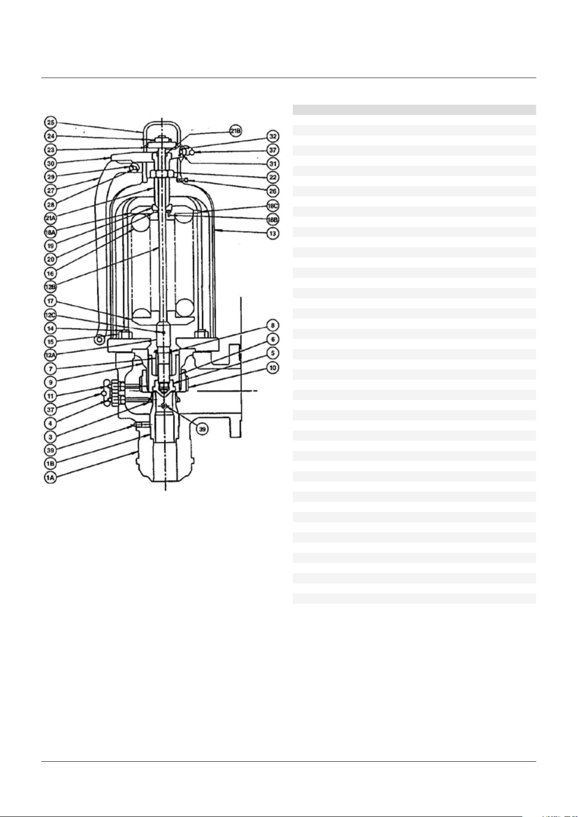
FIGURE 1 - STYLE HC ISOFLEX SAFETY VALVE
PARTS LIST
Part Part name Spare parts*
1A Body
1B Nozzle
3 Nozzle ring 3
4 Nozzle ring set screw
5 Disc insert 1
6 Disc holder 2
7 Disc holder retaining nut
8 Disc holder retaining cotter 1
9 Guide 3
10 Guide ring 3
11 Guide ring set screw
12A Spindle point 3
12B Spindle rod 3
12C Spindle rod pin 3
13 Bonnet
14 Bonnet stud
15 Bonnet stud nut
16 Spring 3
17 Bottom spring washer 3
18A Top spring washer 3
18B Bearing pin 3
18C Locking pin 3
19 Bearing adapter
20 Bearing
21A Adjusting bolt
21B Adjusting bolt bearing
22 Adjusting bolt nut
23 Spindle nut
24 Spindle nut cotter 1
25 Cap
26 Cap set screw
27 Lever
28 Lever pin
29 Lever pin cotter 1
30 Forked lever
31 Forked lever pin
32 Forked lever pin cotter 1
34 Test clamp
36 Test rod
37 Seal and wire
38 Protective hood
39 Drain plug
40 Hydro test plug assembly
41 Nameplate
42 Drive screw
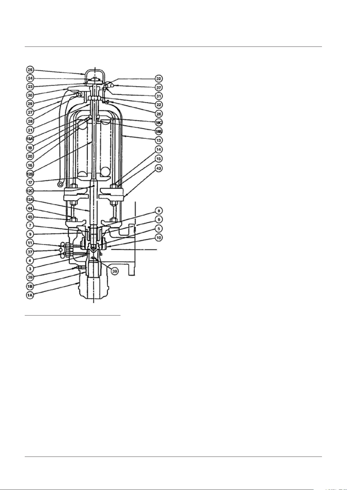
43** Cooling spool
44** Cooling spool stud
45** Cooling spool stud nut
NOTES
* Spare parts designation (see notes 1, 2, 3 in Section 2)
** For Crosby Style HCA ISOFLEX only
2
CROSBY® STYLES HC AND HCA ISOFLEX™ SAFETY VALVES
INSTALLATION, MAINTENANCE AND ADJUSTMENT INSTRUCTIONS
FIGURE 2 - STYLE HCA ISOFLEX SAFETY VALVE
2 INTRODUCTION
Crosby Style HC and HCA ISOFLEX safety
valves have been selected because of their
performance features, reliability and ease
ofmaintenance.
This manual contains information on
installation, hydrostatic testing, field testing
and adjustments and maintenance of these
valves. It is specific to the Isoflex design K
through M
orifice sizes. Adherence to the
2
installation and maintenance procedures
specified in this manual will provide the utmost
in safety, a minimum of maintenance and a
long service life.
Style HC is a high capacity reaction type safety
valve designed for saturated and superheated
steam applications to temperatures of 750°F.
Crosby Style HCA is a high temperature
version of the Style HC, with an alloy steel
construction suitable to temperatures
upto1020°F. TypicallyStyle HCA valves are
used for superheaters and reheater outlets.
DetailsofStyle HC and HCA safety valves,
materials of construction, sizes, pressuretemperature ratings, dimensions, weights and
certified capacities are available on request.
No special tools are necessary for the
maintenance of Style HC and HCA safetyvalves.
However, tools and equipment are available
to ease disassembly and on site testing of
the valves. Such tools and equipment include
the hydraulic set pressure device, the air
set pressure device (see Figure 15) and the
hydraulic jacking device (see Figure 14).
Detailed instructions on their use can be found
in instructions I-11288, T-1652 and I-1167
respectively.
Whenever Style HC/HCA safety valve parts
names are used in this manual, parts numbers
in parenthesis follow. The parts numbers are
an aid to identifying the parts in Figures 1 and 2
and the correlating parts list.
NOTES
1. Consumable spare parts: valve parts which should
be replaced as part of any disassembly, and discs
and disc inserts which must be replaced if seats
are damaged.
2. Repair spare parts: valve parts exposed to wear
and/or corrosion during normal operation.
They are in fluid flow paths and may require
replacement as part of any repair.
3. Insurance spare parts: valve parts exposed to
process or environmental wear and/or corrosion
and may require replacement as part of a
majorrepair.
Emerson recommends that sufficient inventory
of spare parts be maintained to support process
requirements. Always be sure to use genuine
Emerson parts to ensure continued product
performance and warranty.
3
CROSBY® STYLES HC AND HCA ISOFLEX™ SAFETY VALVES
INSTALLATION, MAINTENANCE AND ADJUSTMENT INSTRUCTIONS
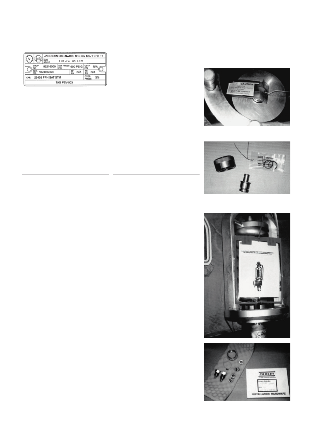
Crosby Style HC/HCA ISOFLEX nameplate
(With sample information for illustrative
purposes only)
Ordering spare parts
When ordering spare parts, the valve size,
style and shop number and/or serial number
should be given together with set pressure,
part name and reference number. The valve
assembly number is shown on the valve
nameplate as 'Shop number'. Spare parts may
be ordered from any Emerson sales office
orrepresentative.
3 DESCRIPTION OF SAFETY VALVES
Crosby Style HC/HCA safety valves are shown
in Figures 1 and 2. These drawings illustrate
the safety valves assembled in cross-section,
and cover the essential elements of the valves.
Approved drawings supplied with the valves
should be used when installation and/or
specific information is required.
Inside the body (1A) is housed the upper portion
of the nozzle (1B), nozzle ring (3), and the
guide ring (10). The disc insert (5) is held in
place in the disc holder (6) by the spindle and
disc holder retainer nut (7). The nozzle ring
and adjusting rings are held in place by the
nozzle ring set screw (4) and the guide ring set
screw(11), which are threaded into the body.
The guide (9) is retained between the body (1A)
and the bonnet (13) by the bonnet studs (14)
and the bonnet studs nuts (15). In the case of
Style HCA valves, a cooling spool (43) is placed
between the body and bonnet to protect the
spring from exposure to extreme temperatures.
The bonnet (13) contains the spring (16),
spring washers (17 and 18) and the spindle
assembly(12). The spindle point is held in
compression between the back face of the disc
insert (5) and the bottom spring washer. The
spring is compressed between the stationary
point of contact with the spindle and the
adjusting bolt (21A) atop the valve bonnet.
The adjusting bolt (21A) is locked in place by the
adjusting bolt nut (22) on top of the bonnet and
within the cap assembly. A means of manual
lifting is provided by the lever (27), lever pin (28),
forked lever (30), forked lever pin (31) and the
spindle nut (23).
4 STORAGE
Often, safety valves are on the job site
months before they are installed. Unless
they are stored properly and protected, their
performance may be affected seriously.
Rough handling may damage flanges or cause
misalignment of the parts. It is best to leave the
safety valves in their shipment cases and store
them in a dry place under cover until they are
tobe installed.
FIGURE 3 - VALVE BODY AS SHIPPED
TOP VIEW - BODY
HYDRO COMPONENTS (see note 1, page 5)
FIGURE 4 - VALVE SUPERSTRUCTURE AS
SHIPPED
4

CROSBY® STYLES HC AND HCA ISOFLEX™ SAFETY VALVES
INSTALLATION, MAINTENANCE AND ADJUSTMENT INSTRUCTIONS
Factory preparation of welded inlet valves
forshipment
All Crosby Style HC and HCA welded inlet safety
valves are equipped with hydrostatic test plugs
and shipped in two parts: valve body and valve
superstructure. This makes handling easier for
installation welding (seeFigures3and 4).
The welded inlet Style HC and HCA safety
valves are specially prepared for shipment
fromthe factory.
After the safety valve is tested as a complete
assembly for set pressure and tightness, the
spring set compression is held by spacer
blocks under the bottom spring washer as
illustrated in Figure 4.
The safety valve superstructure is then
removed from the valve body. The two portions
are boxed and shipped separately. Each portion,
ready for shipment, is illustrated in Figures 3
and 4.
Figure 3 shows the safety valve body as shipped
to the installation site. It is tagged as follows:
• Install and/or weld in place as required
• Prepare for hydrostatic test. See instruction
Hydrostatic plug in place
• Install O-ring and backup ring prior to
hydrostatic test.
Figure 4 shows the safety valve superstructure
as shipped to the installation site. It is boxed
separately from the valve body and is tagged
asfollows:
• Hold for assembly after hydrostatic test.
5 INSTALLATION
Inlet piping
Many safety valves are damaged when first
placed in service because of failure to clean
the connections properly before installation.
The safety valve inlet, the vessel and the line
on which the safety valve is mounted must be
cleaned thoroughly of all foreign matter.
Safety valves should be mounted in a vertical
position, directly on the pressure vessel.
The ASME boiler and pressure vessel code limits
the distance between the safety valve inlet and
the boiler to the length of a standard tee fitting.
The nozzle should have a well-rounded
approach that provides smooth, unobstructed
flow between the vessel and the safety valve.
A safety valve should never be installed on a
fitting having an inside diameter smaller than
the inlet connection of the valve.
Such restriction of flow can cause faulty
valveoperation.
Inlet piping (nozzles) must be designed to
withstand the total resultant forces due to
the safety valve discharging at the maximum
accumulated pressure and the expected
piping loads. The precise nature of the loading
and the resulting stresses will depend on
the configuration of the safety valve and the
discharge piping. Determination of outlet
reaction forces is the responsibility of the
designer of the vessel and/or piping.
Welding of welded inlet valve body to boiler
Welded inlet safety valve bodies should be
welded to the boiler in accordance with
applicable Code requirements. The protective
cover (Figure 3) should be left in place until
ready for the hydrostatic test of the unit.
If visual inspection is necessary, the protective
cover may be removed, but should be replaced.
NOTES
Note 1 to Figure 3
Delivered with the body and packaged in small
bag are the following:
• One O-ring (for hydrostatic test)
• One backup ring (for hydrostatic test)
• One hydrostatic test plug pin
Note 2 to Figure 4
Delivered with the superstructure and
packaged in a small box are the following:
• Valve nozzle ring*
• Valve nozzle ring set screw*
• Valve guide ring set screw*
• Seal wires
* Marked with valve identification number.
NOTE
When the above parts are removed from their boxes,
be sure that the identification of parts to valve number
is maintained and that the parts are stored to facilitate
later recovery for assembly.
Outlet piping
Discharge piping should be simple and
direct. Back pressures built up by discharge
flow affect the operation of safety valves.
Where possible, a short vertical pipe connected
through a long radius elbow discharging
directly into the atmosphere is the most
desirable type of outlet piping.
Discharge piping should not impose any loading
on the safety valve. Excessive discharge piping
loads may cause seat leakage or faulty valve
operation. The inside diameter of the discharge
pipe must never be less than that of the safety
valve outlet.
Valve effluent must discharge to a safe
disposalarea.
Safety valve bodies have pipe thread openings
for drains. These should be connected to
prevent any accumulation of fluid in the valve
body. In addition, discharge piping also should
be drained to prevent any accumulation of fluid.
Care must be taken to ensure that the drains
are directed or piped to a safe disposal area.
5

CROSBY® STYLES HC AND HCA ISOFLEX™ SAFETY VALVES
INSTALLATION, MAINTENANCE AND ADJUSTMENT INSTRUCTIONS
6 HYDROSTATIC TESTING
General information
Depending on the type of inlet, hydrostatic
testing of safety valves may be carried out by
one of three means: blank flanges, test plugs or
test gags. In all cases, hydrostatic test pressure
must be limited to 1½ times the nameplate set
pressure of the valve.
CAUTION
Additionally, hydrostatic test pressure must be
limited to 10% above nameplate set pressure
when a test gag is used.
Welded inlet safety valves
All Style HC/HCA welded inlet safety valves are
prepared for shipment from the factory with
hydrostatic test plugs, as detailed in Section 4 paragraph 'Factory preparation of welded inlet
valves for shipment' and Figure 3.
Hydrostatic tests of these valves shall be
conducted using hydrostatic test plugs as
detailed in paragraph below 'Hydrostatic
testing using hydrostatic test plugs'.
Flanged inlet safety valves
Flanged inlet safety valves should not be
installed for hydrostatic testing. Blank flanges
should be used instead of gagging the safety
valves. This prevents possible damage to the
safety valves due to excessive tightening of
the gag screws or leakage during hydrostatic
test which may result in costly repairs.
Blank flanges must be removed and the
safety valve reinstalled before the vessel
isplacedinservice.
If blank flanges are not used and the safety
valves are to be installed for hydrostatic
tests, Emerson recommends that hydrostatic
test plugs be used for hydrostatic test.
The detailed procedure is outlined in the
paragraph following. Hydrostatic test plugs for
flanged valves are optional equipment and are
providedonly when ordered.
Remove the protective cover from the valve
body. Unscrew the cap from the nozzle.
Remove the test plug from the nozzle bore.
• Preparation for hydrostatic testing Flanged inlet safety valves
Flanged inlet safety valves are shipped
from the factory fully assembled. To use
the hydrostatic test plug, the valve must
be disassembled according to Section 9 paragraph 'Disassembly retaining spring
compression'.
• Installation of hydrostatic test plug
(seeFigure 3)
Inspect the hydrostatic test plug O-ring
groove.
Note: make sure the groove in the plug
isclean.
Install the O-ring and backup ring in the
testplug groove.
CAUTION
Be sure the test plug is seated on the 45°
angleonthe nozzle inside diameter.
Replace the test plug in the nozzle bore.
Place the test plug cap over the plug and
screwit down hand-tight.
CAUTION
Make sure the cap has hand-tight contact with
the plug. Make sure there is enough thread
engagement of the cap onto the nozzle.
Install the test plug pin.
The valve is now ready for hydrostatic test.
• Hydrostatic test
After the above preparation, the safety valve
is ready for hydrostatic test. Observations
should be made at the start of the test to
confirm that the O-rings have been installed
properly and there is no leakage when
pressure is applied.
To aid removal, place the hydrostatic test
plug pin in the hole in the plug extension.
Unscrew the cap, which will engage the plug
pin and exert an upward force as the cap is
turned, thus lifting the plug. Remove from
thevalvenozzle.
Clean the nozzle bore and seat and inspect
the seating surface. If seating surfaces are
damaged, repair according to the directions
in Section 9 - paragraph 'Repair procedure'.
Assemble the valves according to the
instructions in Section 6 - paragraph
'Initialsafety valve assembly'.
Contact Emerson field service for service
equipment (see Section 12 - paragraph
'Service equipment available').
Hydrostatic testing using hydrostatic
testplugs
Before imposing the hydrostatic test pressure
on the vessel or system, perform the following
operations:
CAUTION
Before hydrostatic testing, the O-ring and backup
ring must be installed.
• Preparation for hydrostatic testing Weldedinlet safety valves
The O-ring, backup ring and the test plug
pin are shipped in a box attached to the
superstructure (see Figure 3). The contents
ofthe box are marked for identification.
To install the O-ring and backup ring refer
toFigure 3.
CAUTION
Tightening of the cap will not reduce leakage.
If leakage is evident, remove all pressure from
the vessel or system. Replace the O-ring and
thebackup ring.
WARNING
Do not try to assemble the valve or remove
the steel blocks from under the bottom spring
washerwithout use of proper servicing and
assembly equipment.
• Assembly of valve
After completion of the hydrostatic test,
remove the hydrostatic test plug from
thenozzle.
6
 Loading...