

Emerson Crosby J Series Installation, Operation And Maintenance Manual

CROSBY J SERIES PRESSURE RELIEF VALVE WITH FISHER™ 4320 WIRELESS POSITION MONITOR
INSTALLATION, OPERATION AND MAINTENANCE MANUAL
Before installation, these instructions must be carefully read and understood.
1 INTRODUCTION
TABLE OF CONTENTS
1. Introduction ...................................................1
1.1 General .....................................................1
1.2 Scope ........................................................1
1.3 Safety Precautions ..................................2
2. Calibration Procedure ...................................2
2.1 Magnetic sensor size selection ..............2
2.2 Calibration ...............................................3
3. Mounting Fisher 4320 to the
J- Series Valve ...............................................6
3.1 Installation ...............................................6
3.2 Bracket Kits .............................................7
4. Selection Tables ..............................................8
1.1 General
NOTICE
Refer to Fisher 4320 wireless position monitor
instruction manual for any difficulties with device
or calibration.
The Fisher 4320 Wireless Position Monitor is
used to monitor the lift of a Crosby J Series
Bellows Pressure Relief Valve. This data can be
wirelessly transmitted to a control station.
The Fisher 4320 wireless position monitor is
a true linkage-less non-contacting wireless
position transmitter and limit switch. It is a
rugged measurement device that provides a
precise wireless feedback signal to indicate
equipment position with a percent (%) of span
plus on/off indication. It is designed to be
simple to use, compact, and easily mounted.
The wireless position monitor periodically
reads the position of a measured device and
transmits that data over a wireless network.
1.2 Scope
Calibration of 4320 could be performed before
mounting to the Pressure Relief Valve by
using a calibration device that simulates the
mounting of the 4320 and the magnet sensor,
one can easily calibrate the 4320 by moving
the magnetic sensor. For the large T orifice
JLT-JBS-E, requires a calibration device
simulator due to the length of stroke.
Calibration could be also performed during
mounting to the pressure relief valve by using
calibration plate Emerson provides. This
procedure provides the calibration methods
during mounting 4320 to Crosby J Series
Bellows Pressure relief valve only.
1.3 Safety Precautions
The protection and safety of equipment,
property and personnel depends on the
proper operation of the pressure relief
valves described in this manual. All Emerson
pressure relief valves should be kept in proper
working condition in accordance with the
manufacturer’s written instructions. Periodic
testing and maintenance by the user of this
equipment is essential for reliable and safe
valve operation.
All installation, maintenance, adjustment,
repair and testing performed on pressure
relief valves should be done by qualified
technicians having the necessary skills and
training adequate to perform such work. All
applicable Codes and Standards, governing
regulations and authorities should be adhered
to when performing pressure relief valve
repair. No repair, assembly, adjustment or
testing performed by other than Emerson or
its authorized assemblers and representatives
shall be covered by the warranty extended by
Emerson to its customers. The user should use
only original, factory supplied OEM parts in any
maintenance or repair activity involving this
product.
SAFETY FIRST
To reduce the risk during installation:
• Comply with all information on the product, in
this manual, and in any local and national codes
that apply to this product.
• Do not allow untrained personnel to work with
his product.
• Use Emerson parts and work procedures
specified in this manual.
WARNING
The Crosby J Series valve must have a bellows
when using this position monitor.
Avoid personal injury from sudden release of
process pressure.
Failure to do so may result in injury to personnel
or cause damage to the equipment.
Emerson.com/FinalControl © 2019 Emerson. All rights reserved. VCIOM-11681-EN 19/03

CROSBY J SERIES PRESSURE RELIEF VALVE WITH FISHER™ 4320 WIRELESS POSITION MONITOR
INSTALLATION, OPERATION AND MAINTENANCE MANUAL
WARNING
Sudden release of pressure may result if the valve
assembly is installed where service conditions
could exceed the limits on the appropriate
nameplates. Never use this equipment for any
purpose other than its intended use.
This manual is provided as a general guide for the
assembly or retrofit on the pressure relief valves
described herein. It is not possible to describe all
configurations or variations with such equipment.
The user is advised to contact Emerson or its
authorized assemblers and representatives for
assistance in situations that are not adequately
covered or described in this manual.
Failure to do so may result in injury to personnel
or cause damage to the equipment.
WARNING
Avoid personal injury from sudden release
of process pressure. Before performing any
maintenance operations:
• Do not remove any component from the valve
while the valve is still pressurized.
• Always wear protective gloves, clothing, and
eyewear when performing any maintenance
operations to avoid personal injury.
• Adhere to all safety standards and best
practices for operating the equipment.
• Use bypass valves or completely shut off the
process to isolate the valve from process
pressure. Relieve process pressure on both
sides of the valve. Drain the process media from
both sides of the valve.
• Use lock-out procedures to be sure that the
above measures stay in effect while you work on
the equipment.
• The valve may contain process media that are
pressurized, even when the valve has been
removed from the process.
• Check with your process or safety engineer for
any additional measures that must be taken to
protect against process media.
Failure to do so may result in injury to personnel
or cause damage to the equipment.
The escape of process media indicates that the
valve has NOT been properly vent, or process
pressure is trapped in the valve body. Check
with your process or safety engineer for any
additional measures that must be taken to
protect against process media. Never attempt
to remove the pressure relief valve from a
system that is pressurized. Never adjust
or perform maintenance on the pressure
relief valve while in service unless the valve
is isolated from the system pressure. If not
properly isolated from the system pressure,
the pressure relief valve may inadvertently
open resulting in serious injury. Remove the
pressure relief valve prior to performing any
pressure testing of the system.
CAUTION
When the pressure relief valve is under pressure
never place any part of your body near to the
outlet/exhaust of the valve. Failure to do so may
result in injury to personnel or cause damage to
the equipment.
CAUTION
This product is intended for a specific temperature
range and other application specifications.
Failure to adhere to these specifications could
result in the malfunction of the product, property
damage, or personal injury.
WARNING
If the process media starts to escape from the
valve or pilot, stop immediately!
Failure to do so may result in injury to personnel
or cause damage to the equipment.
The safety of lives and property often depends
on the proper operation of the pressure relief
valve. The valve must be maintained according
to appropriate instructions and must be
periodically tested and reconditioned to ensure
correct function.
WARNING
Use only genuine Emerson replacement parts.
Components that are not supplied by Emerson
should not, under any circumstances, be used.
Use of components not supplied by Emerson
may void your warranty, might adversely affect
the performance of the instrument and could
cause personal injury or property damage.
Failure to do so may result in injury to
personnel or cause damage to the equipment.
NOTICE
Contact your Emerson sales office for
replacement parts.
Before installation, the Installation and
Operational Safety Instructions should be fully
read and understood. These Instructions may
be requested from the factory or are available
at Emerson.com.
2 CALIBRATION PROCEDURE
CAUTION
When the pressure relief valve is under pressure
never place any part of your body near to the
outlet/exhaust of the valve. Never use this
equipment for any purpose other than its intended
use.
Failure to do so may result in injury to personnel
or cause damage to the equipment.
2.1 Magnetic Sensor Size Selection
To achieve an accurate valve position, the
correct magnet size must be selected. Refer to
Table 1 for selection.
CAUTION
The magnet material has been specifically chosen
to provide a long-term stable magnetic field.
However, as with any magnet, care must be taken
when handling the magnet assembly. Another
high-powered magnet placed in close proximity
(less than 25 mm) can cause permanent damage.
Potential sources of damaging equipment include,
but are not limited to: transformers, dc motors,
stacking magnet assemblies.
Failure to do so may result in equipment mal
function.
Tip: As a general rule, do not use less than 50% of
the magnet assembly for full travel measurement.
Performance will decrease as the assembly
is increasingly subranged. The linear magnet
assemblies have a valid travel range indicated by
arrows molded into the piece. This means that the
hall sensor (on the back of the 4320 housing) has to
remain within this range throughout the entire valve
travel. The linear magnet assemblies are symmetrical.
Either end may be up.
2
CROSBY J SERIES PRESSURE RELIEF VALVE WITH FISHER™ 4320 WIRELESS POSITION MONITOR
INSTALLATION, OPERATION AND MAINTENANCE MANUAL
2.2 Calibration
Mounting the Fisher 4320 Wireless
Position Monitor
1. Install a battery into the Fisher 4320
Wireless Position Monitor.
WARNING
Due to the combustible nature of the lithium
content, the power module has special
installation, operation, storage, and/or shipping
requirements. Observe all warnings included with
the power module before installing, operating,
storing, or shipping the 4320 Position monitor.
Failure to do so may result in personal injury or
property damage from fire or explosion.
CAUTION
When installing components, proper means of
electrostatic discharge protection is required.
Failure to use a grounding strap, or other means
of electrostatic discharge protection can result in
damage to the electronics.
CAUTION
To avoid static discharge do not rub or clean the
antenna with solvents.
Failure to do so may result in personal injury or
property damage from fire or explosion.
8. Loosen the Screws on 4320 Bracket and line
up the mark on the back of 4320 with the top
mark on the magnet. Lock 4320 in place on
Bracket with quantity of 4, M6 x 10mm HEX
CAP Screws and Lock Washers with Torque
force listed in Table 2, Location 2. Center
the magnet assembly inside the 4320 slot by
slightly adjusting the magnet bracket, if it is
needed. This represents the “0% position”,
valve closed.
CAUTION
Do not install a magnet assembly that is shorter
than the physical travel of the valve. Loss of
control will result from the magnet assembly
moving outside the range of the index mark in the
feedback slot of the 4320 housing.
Failure to do so may result in personal injury or
property damage.
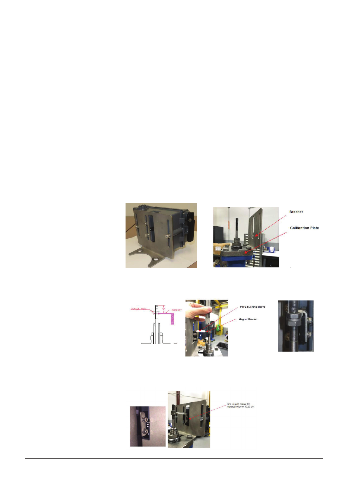
FIGURE 2-1
4320 and Bracket Assembly
FIGURE 2-2
Magnet Alignment
2. Mount the 4320 to the bracket and lightly
tighten screws enough to hold in place. The
screws will be tightened once calibration
step is complete.
3. Mount the calibration plate and bracket on
the pressure relief valve bonnet as shown
on Figure 2-2.
WARNING
Due to the combustible nature of the lithium
content, the power module has special
installation, operation, storage, and/or shipping
requirements. Observe all warnings included with
the power module before installing, operating,
storing, or shipping the 4320 Position monitor.
Failure to do so may result in personal injury or
property damage from fire or explosion.
4. Slide the Polytetrafluoroethylene (PTFE)
bushing sleeve on the magnet bracket.
The PTFE open slot should face in down
direction.
5. Secure the Magnet in place under the bend
in the Magnet Bracket with 2 screws and
lock washers provided with Magnet. Torque
force listed in Table 2, Location 1.
6. Position the magnet bracket assembly to
the valve stem at the dimension “A” shown
in Table 1. Lock in place.
7. Verify dimension “A” by caliper or depth
micrometer to ensure it is in the tolerance
as shown in the Table 1.
FIGURE 2-3
Measurement for Dim A
FIGURE 2-4
Measurement for Dim A
3
 Loading...