

Emerson Crosby HSJ Series Installation, Operation And Maintenance Instructions
CROSBY SERIES HSJ SAFETY VALVES
InstallatIon, operatIon and maIntenance InstructIons
Before installation these instructions must be fully read and understood
WARNING
The safety of lives and property often depends
on the proper operation of the safety valves.
Consequently, the valves should be kept clean and
should be tested periodically and reconditioned to
make sure they function properly.
EMERSON FIELD SERVICE AND REPAIR
PROGRAMS
Field service
Emerson field service provides on-site, in
line testing and repair capability for all types
of pressure relief devices. It is strongly
recommended that on new installations, a
Emerson service engineer be present for
assembly and testing of safety valves.
SPARE PARTS
Emerson recommends spare parts as shown
on the outline drawing Figure 1. When ordering
spare parts, the valve size, style and assembly
number and/or serial number should be
given together with set pressure, part name,
and reference number from Figure 1. The
valve assembly number is shown on the valve
nameplate as 'Shop No'. Spare parts may be
ordered from any Emerson regional sales office
or representative.
SERVICE RECORDS
Service records should be completed before
a valve is returned to service. These records
are important and will provide guidance on
establishing time intervals between repairs as
well as providing the historical record of repairs
and service conditions. Well kept records will
be useful in predicting when to retire a valve
and which spare parts should be maintained in
inventory to ensure uninterrupted plant operation.
Parts
Emerson will help you establish the right mix
of on-site spares with our own distribution and
manufacturing support.
Training
Emerson offers intensive factory or on-site
training seminars to improve maintenance
and application skills.
Testing
Emerson has the capability to evaluate safety
valve operability either in the field or at various
Emerson facilities. Special qualification
programs may also be conducted in our
laboratories.
Contract management
Emerson will combine a group of services to
satisfy your special maintenance needs.
Emerson’ full-spectrum service
• Valve repair
• Field service
• Replacements parts
• Contract management
• Training
• Testing
• Contract
Emerson.com/FinalControl
Engineering Doc. #IS-V3146
© 2017 Emerson. All Rights Reserved. VCIOM-01062-EN 17/12
CROSBY SERIES HSJ SAFETY VALVES
InstallatIon, operatIon and maIntenance InstructIons
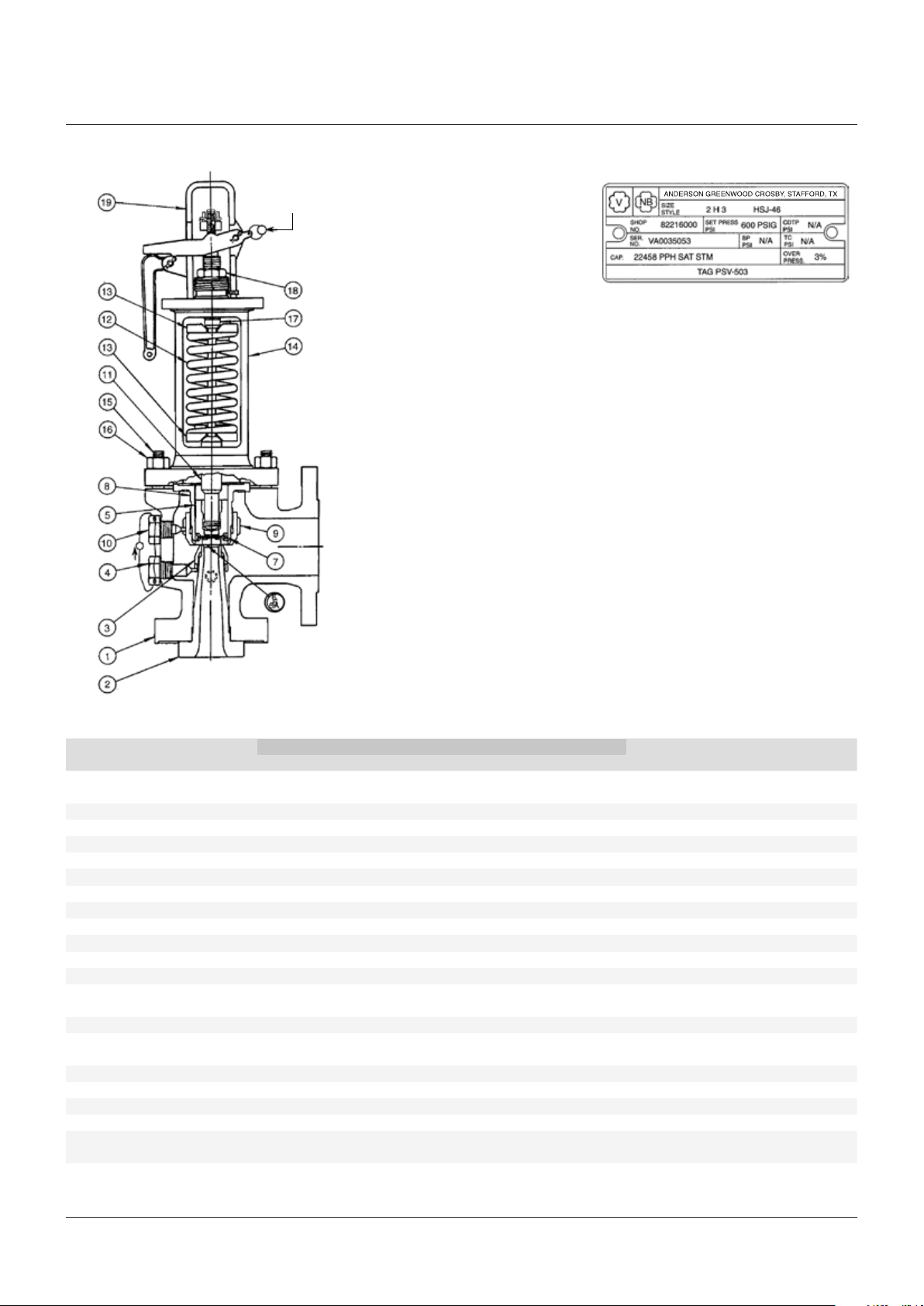
FIGURE 1
Seal and wire
Seal and
wire
NOTES
1. Consumable spare parts: soft goods (gaskets,
etc.) which should be replaced as part of any
disassembly, and disc inserts which must be
replaced if seats are damaged.
2. Repair spare parts: goods exposed to wear and/
or corrosion during normal operation. They are in
fluid flow paths and may require replacement as
part of any repair.
3. Insurance spare parts: hard goods exposed to
process or environmental wear and/or corrosion
and may require replacement as part of a major
repair.
Emerson recommends that sufficient inventory
of spare parts be maintained to support process
requirements.
Always be sure to use genuine Emerson parts to
ensure continued product performance and warranty.
VALVE NAMEPLATE
NOTES
On Series HSJ with closed bonnet option
(except Series HSJ-DOW) the bonnet vent
MUST REMAIN OPEN. Keeping the bonnet vent
open is essential for proper valve operation.
On Series HSJ-DOW (for organic fluid vaporizer
generator applications) use a closed bonnet having
the bonnet vent plugged and Type A screwed cap.
PARTS LIST
Material and maximum temperature
Part No. Part name
1 Body Carbon steel Alloy steel
2 Nozzle Stainless steel Stainless steel 3
3 Nozzle ring Stainless steel Stainless steel 3
4 Nozzle ring set screw Stainless steel Stainless steel 3
5* Disc holder Nickel alloy Nickel alloy 2
6* Disc insert Stainless steel Stainless steel 1
6A* Disc Stainless steel Stainless steel 1
7* Disc insert cotter Stainless steel Stainless steel 1
8 Guide Nickel alloy Nickel alloy 3
9 Guide ring Stainless steel Stainless steel 3
10 Guide ring set screw Stainless steel Stainless steel 3
11 Spindle assembly Stainless steel Stainless steel 3
12 Spring Alloy steel Alloy steel 3
13 Spring washers Steel Steel 3
14 Bonnet Carbon steel Alloy steel
15 Bonnet stud ASME SA-193 Gr. B7 ASME SA-193 Gr. B7
16 Bonnet stud nut ASME SA-194 Gr. 2H ASME SA-194 Gr. 2H
17 Adjusting bolt Stainless steel Stainless steel 3
18 Adjusting bolt nut Steel Steel 3
19 Cap lever assembly Steel/iron Steel/iron
Gaskets Organic fiber non asbestos Organic fiber non asbestos 1
750°F (399°C) 1000°F (538°C)
ASME SA-216 Gr. WCB ASME SA-217 GR. WC6
Corrosion resistant coating Corrosion resistant coating
ASME SA-216 Gr. WCB ASME SA-217 GR. WC6
Spare parts designation
(See notes 1, 2, 3)
* One piece disc (6A) replaces part reference numbers 5, 6 and 7 in orifice sizes F, G, H, and J for CL 150, CL 300 and CL 600.
2
CROSBY SERIES HSJ SAFETY VALVES
InstallatIon, operatIon and maIntenance InstructIons
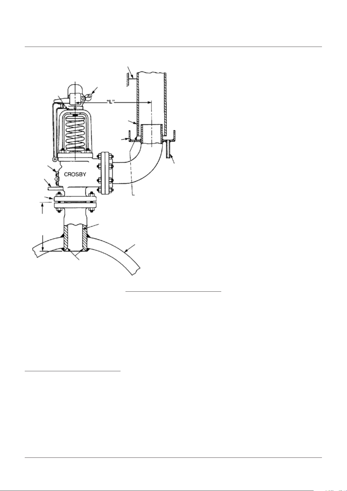
FIGURE 2
Ring positions
stamped here
Wire and
seal
Drain
Shortest
possible
length*
Fixed support anchored to building structure
Seal wire
Discharge pipe
Drip pan
See note **
Recommended minimum diameter ½” larger than valve inlet
Drain
NOTES
Refer to ASME boiler code section 1, pg-71.2
*
** Allow sufficient space to prevent bottoming or side binding of the drip
pan to the discharge pipe under maximum conditions of expansion
Rounded smooth length
CAUTION
The valve should never be lifted or handled using
the lifting lever.
WARNING
To have trouble-free performance be sure to
clean the inlets and outlets of valves thoroughly
before installing. All dirt, sediment and scale in
the protected vessel and piping must be removed
completely before installation (foreignmaterial
entering the valve may cause seat leakage,
plugging and valve malfunction).
1 INTRODUCTION
Crosby Series HSJ safety valves have been
selected because of their performance features,
reliability and ease of maintenance. Adherence
to the installation and maintenance procedures
specified herein will provide the utmost in safety, a
minimum of maintenance and a long service life.
Crosby Series HSJ safety valves are manufactured
in accordance with the requirements of Section 1,
Power Boilers, and Section VIII, Unfired Pressure
Vessels, of the ASME Boiler and Pressure Vessel
Code.
Boiler drum
2 STORAGE AND HANDLING
Often, valves are on hand at the job site months
before they are installed. Unless stored and
protected properly, valve performance may be
affected adversely.
Rough handling and dirt may damage or
cause misalignment of the valve parts. It is
recommended that the valves be left in their
original shipping containers and that they be
stored in a warehouse or at a minimum on a
dry surface with a protective covering until they
are used.
3

CROSBY SERIES HSJ SAFETY VALVES
InstallatIon, operatIon and maIntenance InstructIons
3 INSTALLATION
Rigging
S
afety valves must be handled carefully and
never subjected to sharp impact loads. While
in the shipment case or when uncrated they
should not be bumped or dropped. Rough
handling may alter the pressure setting, deform
valve parts and affect seat tightness adversely.
When it is necessary to use a hoist, a sling
should be placed around the valve body and
bonnet in a manner that will ensure that
the valve is in a vertical position to facilitate
installation.
Flange protectors should remain in place until
the valve is ready to be installed on the system.
Inspection
Safety valves should be inspected visually
before they are installed to ensure that no
damage has occurred during shipment or while
in storage. All protective material, sealing plugs
and any extraneous material inside the valve
body or nozzle must be removed.
The valve nameplate and other identifying tags
should be checked to ensure that the particular
valve is being installed at the location for
which it was intended. The seals protecting the
spring setting and ring adjustments should be
intact. If seals are not intact, the valve should
be inspected, tested and new seals installed
before use.
Inlet piping
Safety valves should be mounted in a vertical
position, directly on the pressure vessel; the
nozzle should have a well-rounded approach
that provides smooth, unobstructed flow
between the vessel and the valve. A safety valve
should never be installed on a fitting having
an inside diameter smaller than the inlet
connection of the valve as restricted flow can
cause faulty valve operation.
Inlet piping (nozzles) must be designed to
withstand the total resultant forces due to the
valve discharging at the maximum accumulated
pressure and the expected piping loads.
The precise nature of the loading and
the resulting stresses will depend on the
configuration of the valve and the discharge
piping. This must be taken into consideration
by those responsible for the installation of the
safety valve and associated vessel or piping.
Determination of outlet reaction forces is the
responsibility of the designer of the vessel and/
or piping.
Many valves are damaged when first placed
into service because of failure to clean the
connections properly when installed. It is
essential that the valve inlet, the vessel and the
line on which the valve is mounted be cleaned
thoroughly of all foreign material. The inlet
connection bolts or studs should be tightened
uniformly to avoid straining or distorting the
valve body.
Outlet piping
Discharge piping should be simple and direct.
Where possible, a short vertical pipe connected
through a long radius elbow discharging
directly into the atmosphere is recommended.
Discharge piping should be designed so as not
to impose any loading on the valve. Excessive
discharge piping may cause seat leakage or
faulty valve operation. The inside diameter of
the discharge pipe must never be less than that
of the valve outlet.
Valve effluent must discharge to a safe disposal
area.
Valve bodies are provided with pipe thread
openings for drains. These should be connected
to prevent any accumulation of fluid in the
valve body. In addition, it is recommended that
discharge piping also be drained to prevent any
accumulation of fluid. Care must be observed
to ensure that the drains are directed or piped
to a safe disposal area.
4
 Loading...