

Emerson CROFTON CF790BS00, CROFTON CF790VNB00, CROFTON CF790SW00, CROFTON CF790VS00 Owner's Manual
READ AND SAVE THESE INSTRUCTIONS
CROFTON
™
58” Ceiling Fan Owner's Manual
Model Numbers
CF790BS00
Brushed Steel with
Walnut/Dark Mahogany Blades
CF790SW00
Satin White with
Satin White/Maple Blades
Net Weight: 25.5 Lbs.
Questions, problems, missing parts: Before returning to the store call
Emerson Electric Customer Service 8 a.m. - 6 p.m., Eastern, Monday-Friday
1-800-654-3545
Part No. F40BP74940000 Form No. BP7494
Revision: 150610 ETL Model No.: CF790
www.emersonfans.com
CF790VNB00
Venetian Bronze with
Walnut/Dark Mahogany Blades
CF790VS00
Vintage Steel with
Walnut/Riverwash Blades
• Español - página 29
• Français - page 57
Table of Contents
Section Page
Safety Instructions . . . . . . . . . . . . . . . . . . . . . . . . . . . .2
1. Unpacking Instructions . . . . . . . . . . . . . . . . . . . . .3-4
2. Electrical Requirements . . . . . . . . . . . . . . . . . . . . .4
3. Ceiling Fan Assembly . . . . . . . . . . . . . . . . . . . .5-10
. How to Hang Your Ceiling Fan . . . . . . . . . . . .11-12
4
5. How to Wire Your Ceiling Fan . . . . . . . . . . . . .13-15
6. Wall Control Procedures . . . . . . . . . . . . . . . . . . . .16
7. Wall Control Installation . . . . . . . . . . . . . . . . . .17-20
8. Programming the Receiver Operating
Frequency . . . . . . . . . . . . . . . . . . . . . . . . . . .21
READ AND SAVE THESE INSTRUCTIONS
Safety Instructions
WARNING
TO REDUCE THE RISK OF FIRE, ELECTRICAL SHOCK,
OR I N J U R Y TO P E R S O N S , OBSERVE T H E
FOLLOWING:
a. Use this unit only in a manner intended by the
manufacturer. If you have questions, contact the
manufacturer.
b. Before servicing or cleaning unit, switch power off
at service panel and lock serv i c e p a n e l
disconnecting means to prevent power from being
switched on a c c i d e n t a l l y . W h e n t h e service
disconnecting means cannot be locked, securely
fa sten a warnin g devic e, s uch as a tag, to the
service panel.
1. Read your owner’s manual carefully and keep it for
future reference.
2. Be careful with the fan and blades when cleaning,
painting, or working near the fan. Always turn off the
power to the ceiling fan before servicing.
3. Do not put anything into the fan blades while they are
turning.
4. Do not operate reversing switch until fan blades have
come to a complete stop.
Additional Safety Instructions for
Installation
1. To avoid possible shock, be sure electricity is turned
off at the fuse box before wiring, and do not operate
fan without blades.
2. All wiring must be in accordance with the National
El ectri cal C ode “AN S I/NF P A 70 -2014 ” an d Lo c al
Electrical Codes. Use the National Electrical Code if
Local Codes do not exist. The ceiling fan must be
grounded as a precaution against possible electrical
sh ock. Ele ctric al insta llat ion sho uld be made or
approved by a licensed electrician.
!
Section Page
9. Using Your Ceiling Fan . . . . . . . . . . . . . . . . . . . .22
10. Maintenance . . . . . . . . . . . . . . . . . . . . . . . . . . . . .23
11. Accessories . . . . . . . . . . . . . . . . . . . . . . . . . . . . .23
12. Instruction to the User . . . . . . . . . . . . . . . . . . . . .23
3. Repair Parts . . . . . . . . . . . . . . . . . . . . . . . . . .24-25
1
14. Trouble Shooting . . . . . . . . . . . . . . . . . . . . . . . . .26
Ceiling Fan Limited Warranty . . . . . . . . . . . . . . . . . .27
Spanish . . . . . . . . . . . . . . . . . . . . . . . . . . . . . . . . . . .29
French . . . . . . . . . . . . . . . . . . . . . . . . . . . . . . . . . . . .57
3. The outlet box and joist must be securely mounted
and capable of reliably supporting at least 50 pounds.
Use only U.L. outlet boxes listed as “Acceptable for
Fan Support of 22.7 kg. (50 lbs.) or less”, and use the
mounting s c r e w s provided w i t h the outlet b o x .
Most outlet boxes commonly used for support of light
fixtures are not acceptable for fan support and may
need to be replaced. Consult a qualified electrician if
in doubt.
4. The downrod furnished wit h the fan provides the
minimum recommended floor to fan blade clearance
for an 8 foot ceiling.
5. The fan must be mounted with the fan blades at least
7 feet from the floor to prevent accidental contact with
the fan blades.
6. Follow the recommended instructions for the proper
method of wiring your ceiling fan. If you do not know
enough about electrical wiring, have your fan installed
by a licensed electrician.
WARNING: To reduce the risk of electrical shock, this
fan must be installed with an isolat ing w all control/
switch.
NOTE: This fan is suitable for use with solid-state speed
controls.
WARNING: To reduce the risk of fire or electrical shock,
this fan should only be used with fan speed control,
Model No. UC7067RA, manufactured by Rhine Electric
Co., Ltd.
WARNING: This product is designed to use only those
parts supplied with this product and/or any accessories
designated specifically for use this product by Emerson
Electric Co. Substitution of parts or accessories not
designated for use with this product by Emerson could
result in personal injury or property damage.
WARNING: To reduce the risk of personal injury, do not
bend the blade flange when installing the blade flanges,
balancing the blades or cleaning the fan. Do not insert
foreign objects in between rotating fan blades.
NOTE: All setscrews must be checked and re-tightened
where necessary before installation.
DATE CODE:
The date code of this fan may be found on the box, stamped in ink on a white label. You should
record this data above and keep it in a safe place for future use.
ETL Model No.: CF790
2
B
A
C
H
I
F
G
OFF ON
....
OFF ON
....
OFF ON
....
OFF ON
....
J
K
D
E
1. Unpacking Instructions
5
10
7
9
8
11
4
1
2 3
6
WARNING
Do not install or use fan if any part is damaged or
missing. Call Toll-Free for replacement parts:
!
1-800-654-3545
WARNING
This pr oduct is de signed to use only those pa rts
supplied with this product and/or any accessories
designated specifically for use with this product by
Emerson Electric Co. Substitution of parts or
accessories not designated for use with this product
by Emerson Electric Co. could result in personal injury
or property damage.
!
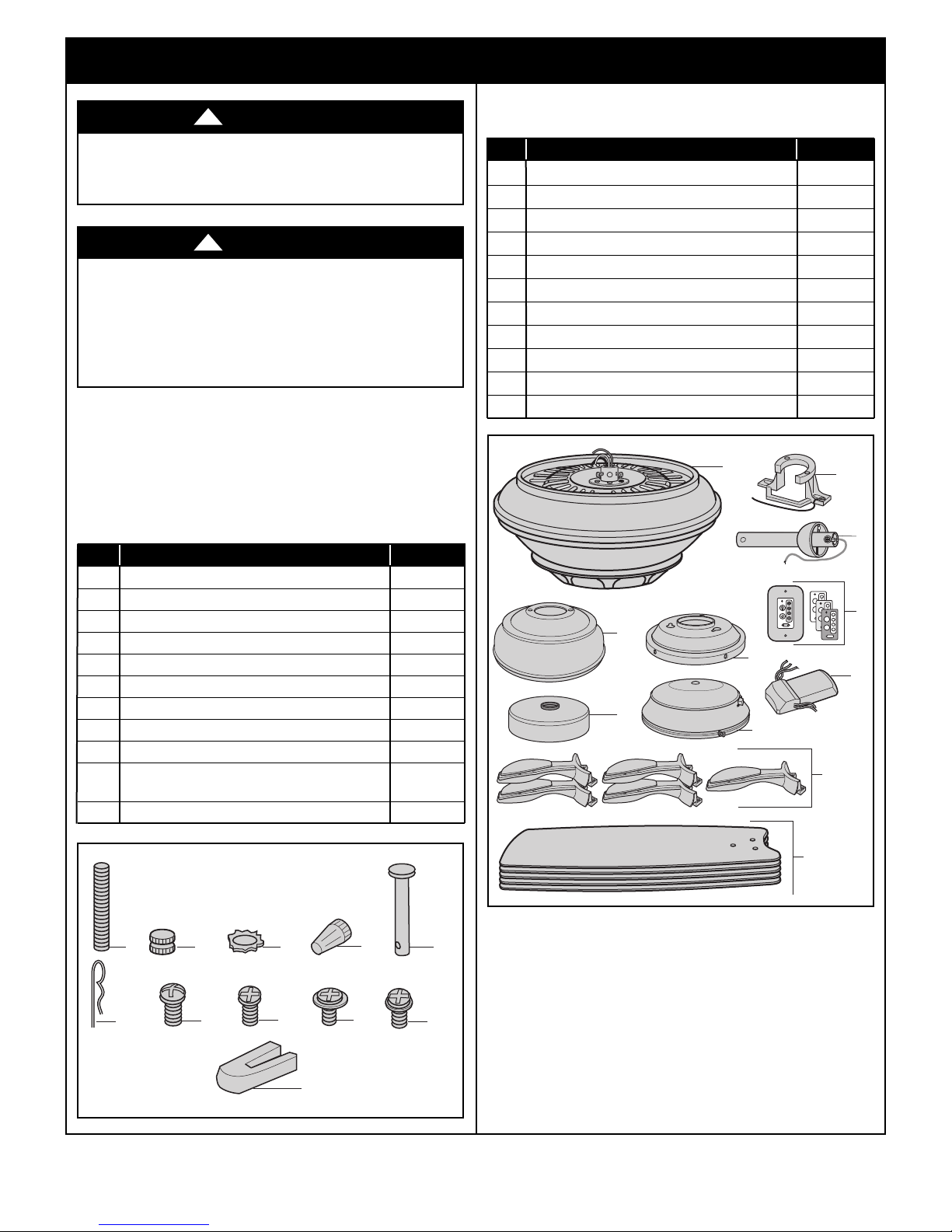
1.1
Check to see that you have received the following parts:
NOTE: If you are uncertain of part description, refer
to exploded view illustration below.
HARDWARE BAG CONTENTS
Part Description Quantity
1 Threaded Studs, #8-32 x 1-1/4” 2
2 Knurled Knobs, #8-32 2
3 Lockwashers, External Tooth #8 2
4 Wire Connectors 3
5 Clevis Pin 1
6 Hairpin Clip 1
7 #8-32 x 5/16” Round Head Screw (spare) 1
8 #8-32 x 5/16” Flat Head Screw (spare) 1
9 #10-32 x 1/4” Washer Head Screws 16
10 1/4-20 x 1/2” Round Head Screws
with Lockwashers 11
11 Blade Balance Kit 1
PACKAGE CONTENTS
Part Description Quantity
A Fan Motor Assembly 1
B Ceiling Canopy 1
C Motor Coupler Cover 1
D Switch Housing Adapter 1
E Switch Housing Assembly 1
F Fan Blade Flanges 5
G Ceiling Fan Reversible Blades 5
H Hanger Bracket 1
I Hanger Ball/4.5” Downrod Assembly 1
J Wall Control w/Hardware 1
K Receiver 1
NOTE: Place the parts from the loose parts bags in
a small container to keep them from being lost.
If any parts are missi n g , c a l l 1 - 800-654-35 4 5
for replacement parts before proceeding.
1.2
Remove th e f a n a s s embly from th e p r o t ective
plastic bag. Place the fan assembly into the upper
styrofoam with the top of the motor facing up.
The upper styrofoam serves as a holder for the fan
during the first stages of assembly.
emersonfans.com
Please contact 1-800-654-3545 for further assistance
3
ETL Model No.: CF790
1. Unpacking Instructions (Continued)
This Manual Is Designed to Make it as Easy as Possible for You to Assemble,
Install, Operate and Maintain Your Ceiling Fan
Tools Needed for Assembly
One Phillips head screwdriver One stepladder
One 1/4” blade screwdriver One wire stripper
Materials
Wiring outlet box and box connectors must be of type
required by the local code. The minimum wire would be
a 3-conductor (2-wire with ground) of following size:
Installed Wire Length Wire Size A.W.G.
Up to 50 ft. 14
50-100 ft. 12
2. Electrical Requirements
Your new ceiling fan will require a grounded electrical
supply line of 120 volts AC, 60 Hz, 15 amp circuit.
WARNING
To reduce the risk of fire, electric shock, or personal
injury, mount fan to outlet box marked “Acceptable for
Fan Support of 22.7 kg. (50 lbs.) or less”, and use
screws supplied with outlet box. Most outlet boxes
commonly used for support of light fixtures are not
acceptabl e for f a n support and may n e e d to be
replaced. Consult a qualified electrician if in doubt.
WARNING
Turning off wall switch is not sufficient. To avoid
possible electrical shock, be sure electricity is turned
off at the main fuse box before wiring. All wiring must
be in accordance with National and Local codes and
the ceilin g fan m u s t be p r o p e rly gr o u n d e d as a
precaution against possible electrical shock.
!
!
WARNING
efore assembling your ceiling fan, refer to section on
B
proper method of wiring your fan (page 13). If you feel
you do no t h a v e e n o u g h w i r i n g k n o w l e d g e or
expe rience, have your fan instal led by a licensed
electrician.
!
Controls Sold Separately
SR400 Remote Control (sold separately) may be used
with this Crofton Ceili n g Fa n . Co n t r ols ar e
recommended for indoor use only.
The outlet box must be securely anchored and capable
of withstanding a load of at least 50 pounds.
If your fan is to replace an existing ceiling light fixture,
turn electricity off at the main fuse box at this time and
remove the existing light fixture.
WARNING
To avoid fire or shock, follow all wiring instructions
carefully.
Any e l e c t r i c a l wo r k no t de s c r i b e d in th e s e
instructions should be done or approved by a licensed
electrician.
Please c a l l Emerson te c h n ical supp o r t at
1- 800-654-354 5 if you ha ve any ques tions about
installation and operation of this ceiling fan.
!
ETL Model No.: CF790
4
3. Ceiling Fan Assembly
SETSCREW
(LOOSENED)
HANGER BALL
4.5" DOWNROD
PIN
4.5" DOWNROD
THREE 80" MOTOR
LEADS (UNTWISTED)
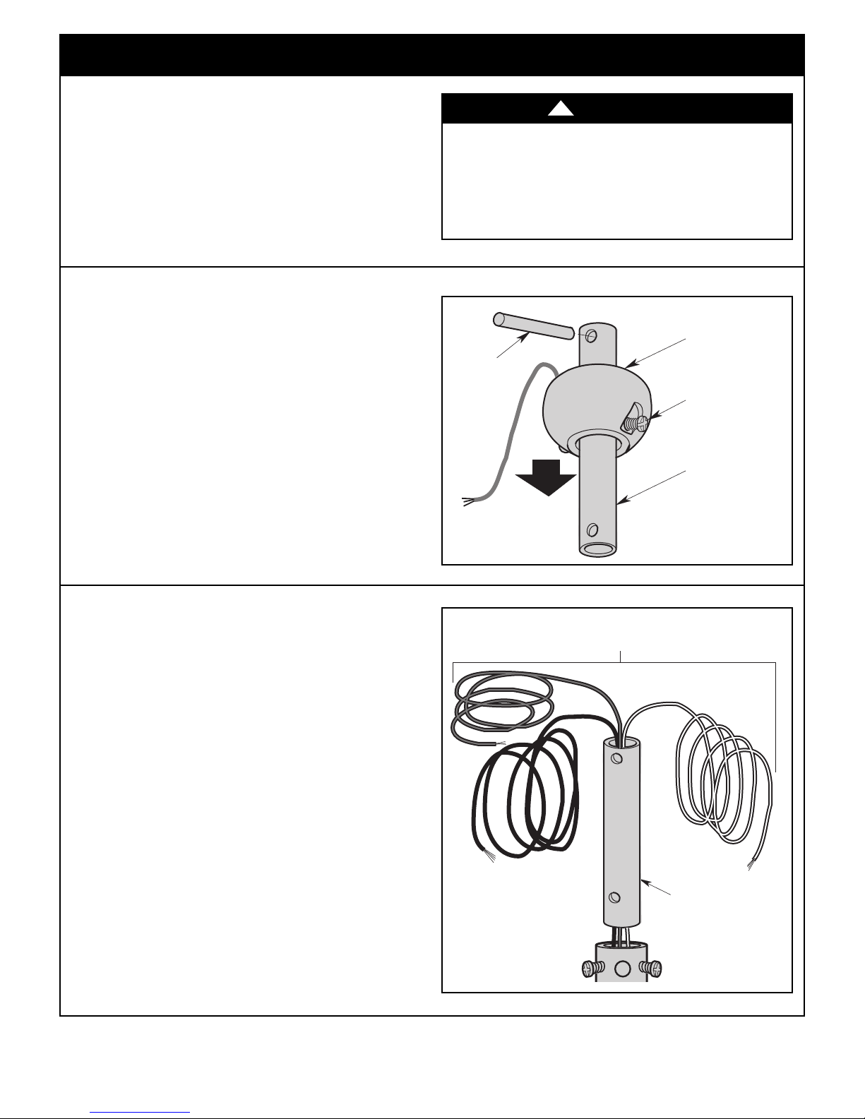
3.1
Disconnect electrical power to the branch circuit at the
circuit breaker or fuse box before attempting to install
he ceiling fan mounting plate on the outlet box.
t
3.2
Remove the hanger ball by loosening the setscrew in
the hanger ball until the ball falls freely down the
downrod (Figure 1).
Remove the pin from the downrod, then remove the
hanger ball.
Retain the pin and hanger ball for reinstallation in
Step 3.8.
NOTE: Do not loosen the screw holding the green
ground wire.
Turning off wall switch is not sufficient. To avoid
possible electrical shock, be sure electricity is turned
off at the main fuse box before wiring. All wiring must
be in accordance with National and Local codes and
the ceilin g fan m u s t be p r o p e rly gr o u n d e d as a
recaution against possible electrical shock.
p
!
WARNING
Figure 1
3.3
Separate, untwist and unkink the three 80” motor leads.
Ro ute th e 80” black, blue a nd whi te mot or leads
through the downrod (Figure 2).
5
Figure 2
emersonfans.com
Please contact 1-800-654-3545 for further assistance
ETL Model No.: CF790
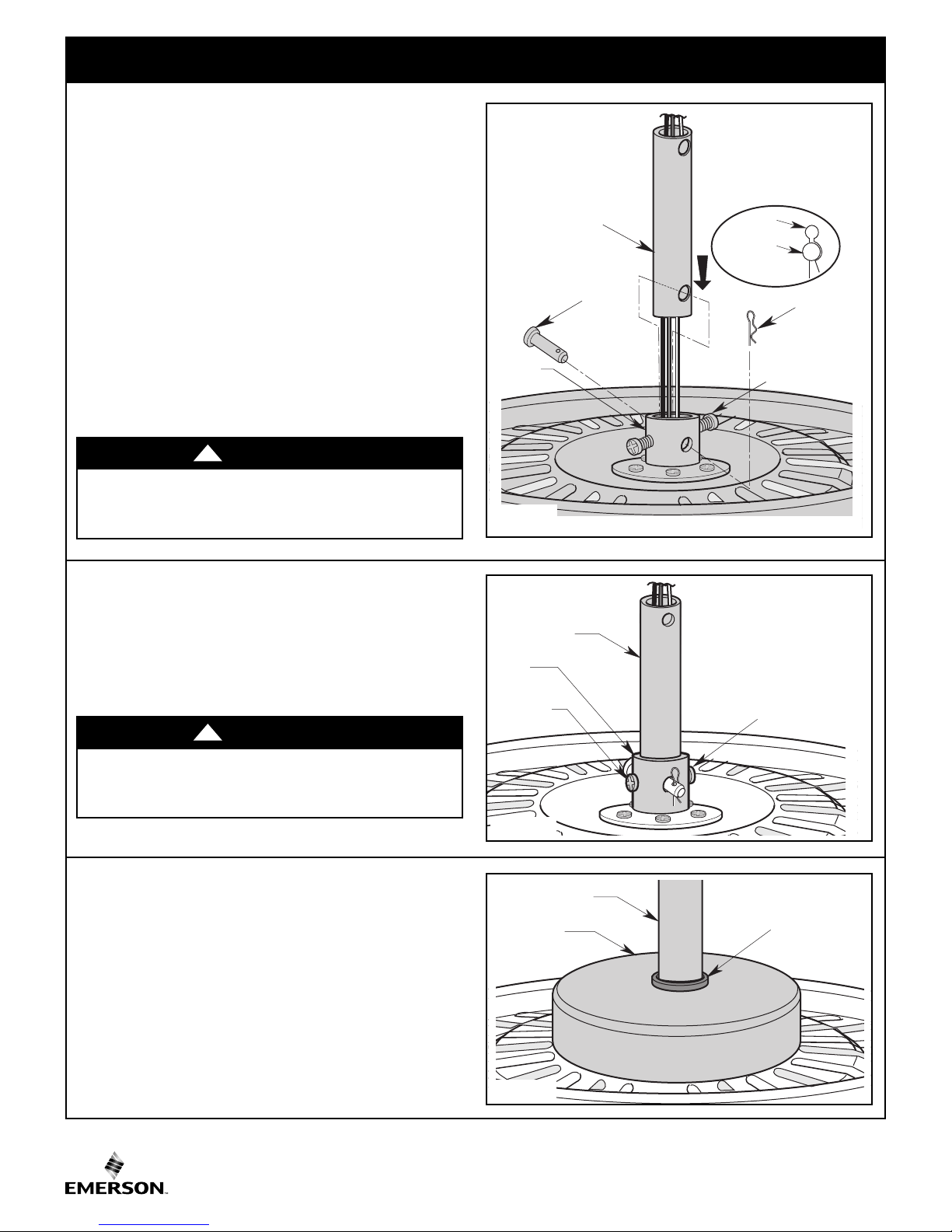
3. Ceiling Fan Assembly (Continued)
MOTOR
COUPLING
4.5"
DOWNROD
CLEVIS
PIN
HAIRPIN
CLIP
HAIRPIN
CLIP
CLEVIS
PIN
LOOSEN
SETSCREWS (2)
RETIGHTEN
SETSCREW
4.5" DOWNROD
COUPLING
COVER
GROMMET
3.4
Loosen the two setscrews in the motor coupling.
Place the 4.5” downrod into the motor coupling, aligning
the clevis pin holes in the downrod with the holes in the
otor coupling (Figure 3).
m
he clevis pin must go through the holes in the motor
T
coupling and the holes in the downrod.
Be sure to push the straight leg of the hairpin clip
through the hole near the end of the clevis pin until the
curved portion of the hairpin clip snaps around the
clevis pin.
The hairpin clip must be properly installed to prevent
the clevis pin from working loose.
Pull on the downrod to make sure the clevis pin is
properly installed.
WARNING
It is critical that the clevis pin in the motor coupling is
properly installed. Failure to verify that the pin is
properly installed could result in the fan falling.
!
3.5
While pulling up on the 4.5” downrod, retighten the two
setscrews (previously loosened) in the motor coupling
to secure the downrod into place (Figure 4).
NOTE: The setscrews must be properly installed as
described above, or fan wobble could result.
WARNING
It is critical that the setscrews are securely tightened.
Fa ilure to verif y th a t th e se tscre w s ar e pr operl y
installed could result in the fan falling.
!
3.6
Make sure the grommet is properly installed in the
coupling cover then slide the coupling cover on the
downrod until it rests on the motor housing (Figure 5).
Figure 3
Figure 4
ETL Model No.: CF790
Figure 5
6
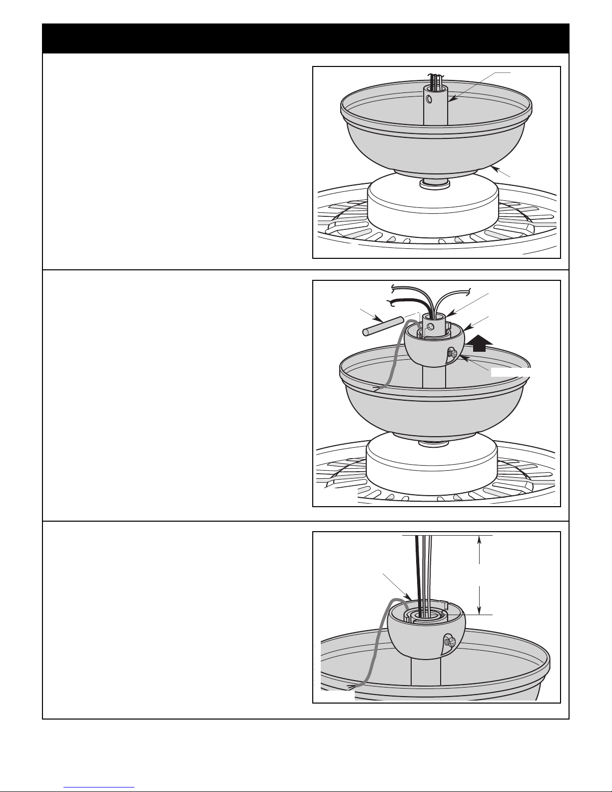
3. Ceiling Fan Assembly (Continued)
4.5"
DOWNROD
CEILING
COVER
4.5" DOWNROD
HANGER BALL
PIN
SETSCREW
HANGER BALL/
DOWNROD
ASSEMBLY
6 to 9
INCHES
3.7
Place the ceiling cover over the downrod. Be sure both
the ceiling cover and the coupling cover are oriented
correctly (Figure 6).
3.8
NOTE: Only use the hanger ball supplied with this
ceiling fan.
Figure 6
Route the three 80” motor leads through the hanger
ball.
Reinstall the hanger ball (Figure 7) on the downrod as
follows:
Position the hanger ball pin through the two holes in the
downrod and align the ball so the pin is captured in the
groove in the top of the hanger ball.
Pul l the h a nger ba l l up ti g ht agai n st the pin and
securely tighten the setscrew in the hanger ball.
NOTE: A loose setscrew could create fan wobble.
3.9
The fan comes with black, blue and white leads that are
80-inches long.
Before installing the fan, measure up approximately
6 t o 9 - i n c h e s above top of hanger ball/downrod
assembly (Figure 8).
Cut off excess leads and strip back insulation 1/2-inch
from end of leads.
Figure 7
7
Figure 8
emersonfans.com
Please contact 1-800-654-3545 for further assistance
ETL Model No.: CF790
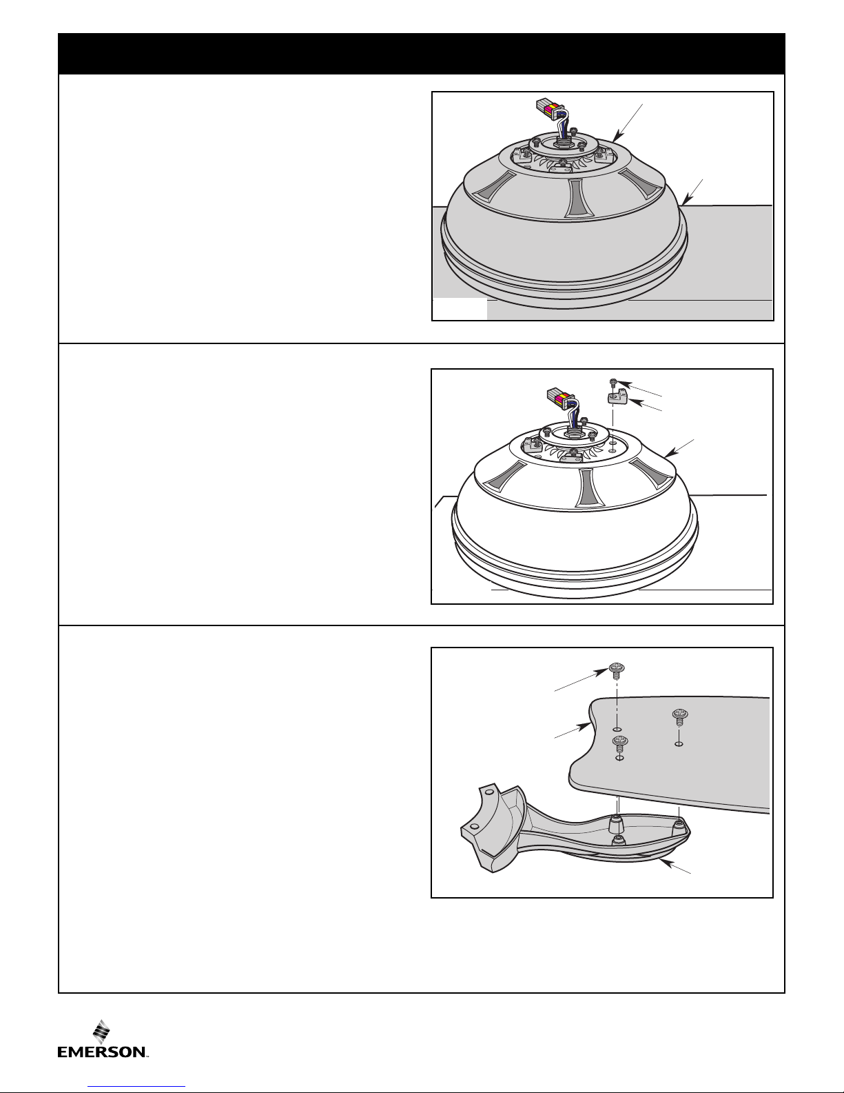
3. Ceiling Fan Assembly (Continued)
STYROFOAM
PARTIALLY
ASSEMBLED
CEILING FAN
SHIPPING SPACER
SHIPPING SPACER
SCREW
FAN
ASSEMBLY
BLADE
FLANGES (5)
#10-32 x 1/4" WASHER
HEAD SCREWS (3)
REVERSIBLE FAN
BLADES (5)
3.10
Carefully turn the partially assembled ceiling fan over
and place it on the styrofoam for final preparation
Figure 9).
(
3.11
Remove t h e shipp i n g spacer s a nd the s p acer
attachment screws from the motor before installation of
blade assemblies (Figure 10).
Discard the spacers and spacer screws.
Figure 9
3.12
Your ceiling fan is supplied with one set of 5 reversible
fan blades. Choose the finish to compliment your decor
and mount the blades to the blade flanges as follows:
Mount blade flanges to ceiling fan blades using three
#10-32 x 1/4” wa s h e r head s crews ( s u p plied)
(Figure 11).
Repeat this procedure for the other four fan blades and
blade flanges.
Figure 10
Figure 11
ETL Model No.: CF790
8
3. Ceiling Fan Assembly (Continued)
1/4-20 x 1/2" ROUND HEAD
SCREWS WITH LOCKWASHERS
(2 per blade/flange assembly)
BLADE/FLANGE ASSEMBLIES (5)
MOTOR HUB
INTERLOCKING FLANGE AREA
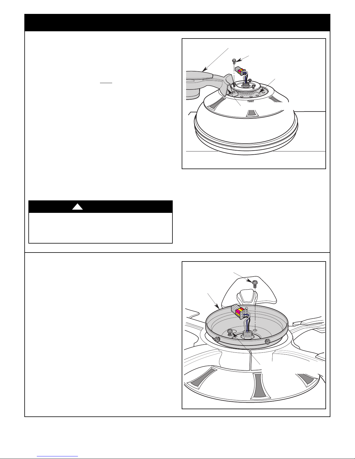
SWITCH
HOUSING
ADAPTER
REMOVE ONE #8-32 x 5/16"
ROUND HEAD SCREW
LOOSEN TWO #8-32 x 5/16"
ROUND HEAD SCREWS
3.13
Loosely attach one blade/flange assembly to the motor
hub by securing the two 1/4-20 x 1/2” round head
crews with lockwashers (Figure 12).
s
Make sure the screws are NOT
procedure for other four blade/flange assemblies.
NOTE: The blad e flanges have an int erlocking
featur e t hat mus t b e fully e n g aged be f o r e
tightening the screws. Make sure all the flanges are
pr o perly e ngaged and the n tight en the flange
screws. If one of the flanges does not seat properly
on the mot or hub, loosen t he adja cent fla nge
screws, re-engage and reseat the flanges, then
tighten the screws again.
tightened. Repeat this
3.14
Once all five blade/flange assemblies are secured to
the motor hub, proceed to tightening all 1/4-20 x 1/2”
round head screws with lockwashers at this time.
WARNING
To reduce the risk of personal injury, do not bend the
blade f l a n g e when installing t h e blade flanges,
balancing the blades or cleaning the fan. Do not insert
foreign objects in between rotating fan blades.
!
Figure 12
3.15
Remove one #8-32 x 5/16” round head screw from the
motor housing (reserve for later use).
Loosen the other two screws to assemble the switch
housing adapter to the motor housing (Figure 13).
3.16
Rotate the switch housing adapter to engage the two
loosened screws in the two key hole slots.
Replace the #8-32 x 5/16” round head screw (removed
previously) and tighten all three screws to secure the
switch housing adapter to the motor housing.
NOTE: Make sure wires are not pinched between
the switch housing adapter and the motor housing.
Spare #8-32 x 5/16” round head screw is provided in
parts bag if needed.
9
Figure 13
emersonfans.com
Please contact 1-800-654-3545 for further assistance
ETL Model No.: CF790
 Loading...