

Page 1
100-214-294 - REV. 05
Bransonic
Ultrasonic Bath
Instruction Manual
Branson Ultrasonics Corporation
41 Eagle Road
Danbury, CT 06813-1961 USA
(203) 796-0400
http://www.bransonultrasonics.com
Page 2

Manual Change Information
At Branson, we strive to maintain our position as the leader in ultrasonics plastics joining,
metal welding, cleaning and related technologies by continually improving our circuits and
components in our equipment. These improvements are incorporated as soon as they are
developed and thoroughly tested.
Information concerning any improvements will be added to the appropriate technical
documentation at its next revision and printing. Therefore, when requesting service
assistance for specific units, note the Revision information found on the cover of this
document, and refer to the printing date which appears at the bottom of this page.
Copyright and Trademark Notice
Copyright © 2017 Branson Ultrasonics Corporation. All rights reserved. Contents of this publication may not be
reproduced in any form without the written permission of Branson Ultrasonics Corporation.
Mylar is a registered trademark of DuPont Teijin Films.
Loctite is a registered trademark of Loctite Corporation.
WD-40 is a registered trademark of WD-40 Company.
Windows 7, Windows Vista, and Windows XP are registered trademarks of Microsoft Corporation
Other trademarks and service marks mentioned herein are held by their respective
owners.
ii 100-214-294 REV. 05
Page 3

Foreword
Congratulations on your choice of a Branson Ultrasonics Corporation system!
The Branson Ultrasonic Bath system is process equipment for the cleaning of parts using
ultrasonic energy. It is the newest generation of product using this sophisticated
technology for a variety of customer applications. This Instruction Manual is part of the
documentation set for this system, and should be kept with the equipment.
Thank you for choosing Branson!
Introduction
This manual is arranged into several structured chapters which will help you find the
information you may need to know to safely handle, install, set up, program, operate,
and/or maintain this product. Please refer to the Table of Contents and/or the Index of
this manual to find the information you may be looking for. In the event you require
additional assistance or information, please contact our Product Support department (see
1.3 Limited Warranty for information on how to contact them) or your local Branson
representative.
100-214-294 REV. 05 iii
Page 4

iv 100-214-294 REV. 05
Page 5

Table of Contents
Chapter 1:Safety and Support
1.1 Safety Requirements and Warnings . . . . . . . . . . . . . . . . . . . . . . . . . . . . . . . . . . . 2
1.2 Safety Precautions. . . . . . . . . . . . . . . . . . . . . . . . . . . . . . . . . . . . . . . . . . . . . . . 3
1.3 Limited Warranty. . . . . . . . . . . . . . . . . . . . . . . . . . . . . . . . . . . . . . . . . . . . . . . . 5
Chapter 2:Introduction
2.1 How Ultrasonics Works. . . . . . . . . . . . . . . . . . . . . . . . . . . . . . . . . . . . . . . . . . . . 8
2.2 Ultrasonic Baths . . . . . . . . . . . . . . . . . . . . . . . . . . . . . . . . . . . . . . . . . . . . . . . . 9
Chapter 3:Delivery and Handling
3.1 Unpacking Your Unit . . . . . . . . . . . . . . . . . . . . . . . . . . . . . . . . . . . . . . . . . . . . .12
Chapter 4:Technical Specifications
4.1 Model Name Definition . . . . . . . . . . . . . . . . . . . . . . . . . . . . . . . . . . . . . . . . . . . .14
4.2 Equipment Specifications . . . . . . . . . . . . . . . . . . . . . . . . . . . . . . . . . . . . . . . . . .15
4.3 Temperature. . . . . . . . . . . . . . . . . . . . . . . . . . . . . . . . . . . . . . . . . . . . . . . . . . .21
4.4 Cleaning Solutions. . . . . . . . . . . . . . . . . . . . . . . . . . . . . . . . . . . . . . . . . . . . . . .22
4.5 Solution Effect on Metals . . . . . . . . . . . . . . . . . . . . . . . . . . . . . . . . . . . . . . . . . .24
Chapter 5:Installation and Setup
5.1 Installing Your Unit . . . . . . . . . . . . . . . . . . . . . . . . . . . . . . . . . . . . . . . . . . . . . .28
Chapter 6:Operation
6.1 Operating Your Ultrasonic Bath . . . . . . . . . . . . . . . . . . . . . . . . . . . . . . . . . . . . . .30
6.2 M Series. . . . . . . . . . . . . . . . . . . . . . . . . . . . . . . . . . . . . . . . . . . . . . . . . . . . . .31
6.3 MH Series. . . . . . . . . . . . . . . . . . . . . . . . . . . . . . . . . . . . . . . . . . . . . . . . . . . . .34
6.4 CPX Series . . . . . . . . . . . . . . . . . . . . . . . . . . . . . . . . . . . . . . . . . . . . . . . . . . . .37
6.5 CPXH Series . . . . . . . . . . . . . . . . . . . . . . . . . . . . . . . . . . . . . . . . . . . . . . . . . . .43
6.6 Cleaning Methods . . . . . . . . . . . . . . . . . . . . . . . . . . . . . . . . . . . . . . . . . . . . . . .59
Chapter 7:Maintenance
7.1 Optimizing Your Ultrasonic Bath . . . . . . . . . . . . . . . . . . . . . . . . . . . . . . . . . . . . .64
7.2 Troubleshooting . . . . . . . . . . . . . . . . . . . . . . . . . . . . . . . . . . . . . . . . . . . . . . . .65
7.3 Glass Slide Test. . . . . . . . . . . . . . . . . . . . . . . . . . . . . . . . . . . . . . . . . . . . . . . . .67
7.4 Service Centers. . . . . . . . . . . . . . . . . . . . . . . . . . . . . . . . . . . . . . . . . . . . . . . . .68
7.5 Information for Users on Disposal of Equipment . . . . . . . . . . . . . . . . . . . . . . . . . .71
100-214-294 REV. 05 v
Page 6

vi 100-214-294 REV. 05
Page 7

List of Figures
Chapter 1:Safety and Support
Chapter 2:Introduction
Chapter 3:Delivery and Handling
Chapter 4:Technical Specifications
Chapter 5:Installation and Setup
Chapter 6:Operation
Figure 6.1 M Series Controls . . . . . . . . . . . . . . . . . . . . . . . . . . . . . . . . . . . . . . . . . . . . . . .32
Figure 6.2 MH Series Controls . . . . . . . . . . . . . . . . . . . . . . . . . . . . . . . . . . . . . . . . . . . . . .35
Figure 6.3 CPX Series Controls . . . . . . . . . . . . . . . . . . . . . . . . . . . . . . . . . . . . . . . . . . . . . .38
Figure 6.4 CPXH Series Controls. . . . . . . . . . . . . . . . . . . . . . . . . . . . . . . . . . . . . . . . . . . . .44
Figure 6.5 Draining of Units 1800 and 2800. . . . . . . . . . . . . . . . . . . . . . . . . . . . . . . . . . . . .55
Figure 6.6 Direct Cleaning Method . . . . . . . . . . . . . . . . . . . . . . . . . . . . . . . . . . . . . . . . . . .59
Figure 6.7 Indirect Cleaning Method . . . . . . . . . . . . . . . . . . . . . . . . . . . . . . . . . . . . . . . . . .60
Figure 6.8 Non Cleaning Application . . . . . . . . . . . . . . . . . . . . . . . . . . . . . . . . . . . . . . . . . .61
Chapter 7:Maintenance
100-214-294 REV. 05 vii
Page 8

viii 100-214-294 REV. 05
Page 9

List of Tables
Chapter 1:Safety and Support
Chapter 2:Introduction
Table 2.1 Ultrasonic Baths Available . . . . . . . . . . . . . . . . . . . . . . . . . . . . . . . . . . . . . . . . . 9
Chapter 3:Delivery and Handling
Chapter 4:Technical Specifications
Table 4.1 Model Name Definition . . . . . . . . . . . . . . . . . . . . . . . . . . . . . . . . . . . . . . . . . . . .14
Table 4.2 Equipment Specifications for North America Models. . . . . . . . . . . . . . . . . . . . . . . .15
Table 4.3 Equipment Specifications for Europe Models . . . . . . . . . . . . . . . . . . . . . . . . . . . . .16
Table 4.4 Equipment Specifications for Japan Models. . . . . . . . . . . . . . . . . . . . . . . . . . . . . .17
Table 4.5 Equipment Specifications for China Models . . . . . . . . . . . . . . . . . . . . . . . . . . . . . .18
Table 4.6 Fuse Table for North America and Japan Models . . . . . . . . . . . . . . . . . . . . . . . . . .19
Table 4.7 Fuse Table for Europe and China Models . . . . . . . . . . . . . . . . . . . . . . . . . . . . . . .20
Table 4.8 Temperature. . . . . . . . . . . . . . . . . . . . . . . . . . . . . . . . . . . . . . . . . . . . . . . . . . .21
Table 4.9 Alkaline Solution Strength and Uses . . . . . . . . . . . . . . . . . . . . . . . . . . . . . . . . . .22
Table 4.10 Chemicals Harmful to Your Tank . . . . . . . . . . . . . . . . . . . . . . . . . . . . . . . . . . . . .23
Table 4.11 Solution Effects on Metals. . . . . . . . . . . . . . . . . . . . . . . . . . . . . . . . . . . . . . . . . .24
Chapter 5:Installation and Setup
Chapter 6:Operation
Table 6.1 Before you Begin. . . . . . . . . . . . . . . . . . . . . . . . . . . . . . . . . . . . . . . . . . . . . . . .31
Table 6.2 M Series Explanation of Controls . . . . . . . . . . . . . . . . . . . . . . . . . . . . . . . . . . . . .32
Table 6.3 For initial cleaning solution degassing. . . . . . . . . . . . . . . . . . . . . . . . . . . . . . . . . .32
Table 6.4 Treating Samples . . . . . . . . . . . . . . . . . . . . . . . . . . . . . . . . . . . . . . . . . . . . . . .33
Table 6.5 Before you Begin. . . . . . . . . . . . . . . . . . . . . . . . . . . . . . . . . . . . . . . . . . . . . . . .34
Table 6.6 MH Series Explanation of Controls . . . . . . . . . . . . . . . . . . . . . . . . . . . . . . . . . . . .35
Table 6.7 For initial cleaning solution degassing. . . . . . . . . . . . . . . . . . . . . . . . . . . . . . . . . .35
Table 6.8 Treating Samples . . . . . . . . . . . . . . . . . . . . . . . . . . . . . . . . . . . . . . . . . . . . . . .36
Table 6.9 Before you begin. . . . . . . . . . . . . . . . . . . . . . . . . . . . . . . . . . . . . . . . . . . . . . . .37
Table 6.10 CPX Series explanation of controls. . . . . . . . . . . . . . . . . . . . . . . . . . . . . . . . . . . .38
Table 6.11 CPX Series LCD description. . . . . . . . . . . . . . . . . . . . . . . . . . . . . . . . . . . . . . . . .40
Table 6.12 Degassing your CPX Series unit. . . . . . . . . . . . . . . . . . . . . . . . . . . . . . . . . . . . . .41
Table 6.13 Treating Samples . . . . . . . . . . . . . . . . . . . . . . . . . . . . . . . . . . . . . . . . . . . . . . .42
Table 6.14 Before you begin. . . . . . . . . . . . . . . . . . . . . . . . . . . . . . . . . . . . . . . . . . . . . . . .43
Table 6.15 CPXH Series explanation of controls. . . . . . . . . . . . . . . . . . . . . . . . . . . . . . . . . . .44
Table 6.16 LCD Description for CPXH Series. . . . . . . . . . . . . . . . . . . . . . . . . . . . . . . . . . . . .48
Table 6.17 Degassing . . . . . . . . . . . . . . . . . . . . . . . . . . . . . . . . . . . . . . . . . . . . . . . . . . . .49
Table 6.18 Ultrasonic Operating Modes . . . . . . . . . . . . . . . . . . . . . . . . . . . . . . . . . . . . . . . .50
Table 6.19 Treating samples in Timed Sonics Mode . . . . . . . . . . . . . . . . . . . . . . . . . . . . . . . .51
Table 6.20 Treating Samples in Constant Sonics Mode. . . . . . . . . . . . . . . . . . . . . . . . . . . . . .52
Table 6.21 Treating Samples in Auto Mode. . . . . . . . . . . . . . . . . . . . . . . . . . . . . . . . . . . . . .53
Table 6.22 CPXH temperature calibration . . . . . . . . . . . . . . . . . . . . . . . . . . . . . . . . . . . . . . .54
Table 6.23 Draining your ultrasonic bath . . . . . . . . . . . . . . . . . . . . . . . . . . . . . . . . . . . . . . .55
Table 6.24 Measuring the Solution Temperature . . . . . . . . . . . . . . . . . . . . . . . . . . . . . . . . . .57
Table 6.25 Solution Usage . . . . . . . . . . . . . . . . . . . . . . . . . . . . . . . . . . . . . . . . . . . . . . . . .58
100-214-294 REV. 05 ix
Page 10

Chapter 7:Maintenance
Table 7.1 Tanks . . . . . . . . . . . . . . . . . . . . . . . . . . . . . . . . . . . . . . . . . . . . . . . . . . . . . . . 64
Table 7.2 Troubleshooting . . . . . . . . . . . . . . . . . . . . . . . . . . . . . . . . . . . . . . . . . . . . . . . . 65
Table 7.3 Authorized Service Centers (North America) . . . . . . . . . . . . . . . . . . . . . . . . . . . . 68
Table 7.4 Technical Support (North America) . . . . . . . . . . . . . . . . . . . . . . . . . . . . . . . . . . . 68
Table 7.5 Authorized Service Center/Technical Support (Europe) . . . . . . . . . . . . . . . . . . . . . 69
Table 7.6 Authorized Service Center/Technical Support (Asia) . . . . . . . . . . . . . . . . . . . . . . . 69
x 100-214-294 REV. 05
Page 11

Chapter 1: Safety and Support
1.1 Safety Requirements and Warnings. . . . . . . . . . . . . . . . . . . . . . . . . . . 2
1.2 Safety Precautions . . . . . . . . . . . . . . . . . . . . . . . . . . . . . . . . . . . . . . . . 3
1.3 Limited Warranty . . . . . . . . . . . . . . . . . . . . . . . . . . . . . . . . . . . . . . . . . 5
100-214-294 REV. 05 1
Page 12

1.1 Safety Requirements and Warnings
This chapter contains an explanation of the different Safety Notice symbols and icons
found both in this manual and on the product itself and provides additional safety
information for ultrasonic welding. This chapter also describes how to contact Branson for
assistance.
2 100-214-294 REV. 05
Page 13

1.2 Safety Precautions
Before using your Ultrasonic Bath, please read and thoroughly understand these safety
precautions. Failure to follow them may result in serious personal injury or property
damage.
1.2.1 To avoid electrical shock:
• Do unplug from power source before filling or emptying the tank
• Do plug the unit into an appropriate grounded power socket
• Do connect the unit to a power supply using a properly sized overcurrent protection device. See
label on the back of unit for information on current rating
• Do keep the control panel and the area around the unit clean and dry—wipe up solution which
spills over the tank brim. Water and high voltage can cause electrical shock
• Do not operate the unit without proper grounding
• Do not remove the grounding prong on the line cord plug
• Do not disassemble your unit—high voltage inside the unit is dangerous
• Do not immerse the unit in water
1.2.2 To prevent personal and/or property damage:
• Do use water-based solutions
• Do not ever use alcohol, gasoline or flammable solutions. Doing so could cause a fire or explosion
and will void your warranty. Use only water-based solutions
• Do not ever use mineral acids. These could damage the tank
• Do not touch the stainless steel tank or cleaning solution—they may be hot
• Do not allow fluid temperature to exceed 70° C (158° F)
• Do not place your fingers or hands into the tank while the unit is operating. Doing so may cause
discomfort and possible skin irritation. Avoid contact with solutions and provide adequate
ventilation
• Do not use solutions containing chlorine bleach
1.2.3 To prevent damage to the unit:
• Do change your solution regularly
• Do not cover vents on the cover
• Do not operate the unit dry
• Do not place parts or containers directly on the bottom of the tank; use a tray or wire to suspend
items. Failure to comply may cause transducer damage and will void your warranty
• Do not allow the solution to drop more than 3/8 inch (1 cm) below the operating level line with
heat or ultrasonics on. Failure to comply may cause transducer and/or heater damage and will
void your warranty
• Turn off AC and heater switch before plugging/unplugging the line cord
1.2.4 Sound level and energy savings
• Do not operate the unit without a cover when possible
• The sound pressure released by the unit depends on the size of the bath and the application, but
is less than 80 dBA when used with a cover
• To reduce the sound pressure it is recommended to use a cover while ultrasonics are activated
and to switch the ultrasonics on with the bath loaded when possible
1.2.5 Insulation resistance test
Branson has taken all applicable measures to assure that manufactured units comply with
insulation resistance requirements, as outlined by IEC 61010-1:2010 (Third edition). As
100-214-294 REV. 05 3
Page 14

per the Portable Appliance Testing (PAT) requirements, testing should be carried out by
the user.
Before doing the insulation testing, however, please read the following pertinent
information:
All of Branson's 220 V "C" and 230 V "E" units are equipped with Metal Oxide Varistors
(MOVs) as the primary components to absorb overvoltages in the power line. MOVs
disperse the over-voltage to the ground line and thus away from the equipment. Per their
mode of operation, these MOVs will cause the insulation resistance test to fail when it is
carried out at 500 V DC. As such, Branson recommends performing the test at a reduced
voltage (250 V DC), as allowed by the Code of Practice for In-service Inspection and
Testing of Electrical Equipment published by the IET (The Institution of Engineering and
Technology), as this will prevent the MOVs from triggering and failing the test.
4 100-214-294 REV. 05
Page 15
1.3 Limited Warranty
Subject to the limitations outlined below, Branson warrants that the Ultrasonic Baths will
be free from defects in material and workmanship under normal use and regular service
and maintenance for a period of twenty four (24) months from the date of
shipment. Branson does not warrant that the operation of the software shall be
uninterrupted or error free. THIS IS THE SOLE AND EXCLUSIVE WARRANTY GIVEN WITH
RESPECT TO THE ULTRASONIC BATHS AND IS IN LIEU OF AND EXCLUDES ALL OTHER
WARRANTIES, EXPRESS OR IMPLIED, ARISING BY OPERATION OF LAW OR OTHERWISE,
INCLUDING WITHOUT LIMITATION, MERCHANTABILITY AND FITNESS FOR A PARTICULAR
PURPOSE WHETHER OR NOT THE PURPOSE OR USE HAS BEEN DISCLOSED TO BRANSON.
This warranty does not extend to any losses or damages due to misuse, accident, abuse,
neglect, normal wear and tear, negligence (other than Branson's), unauthorized
modification or alteration, use beyond rated capacity, unsuitable power sources or
environmental conditions, improper installation, repair, handling, maintenance or
application or any other cause not the fault of Branson. If within thirty (30) days after
discovery of any warranty defects within the warranty period, the Customer notifies
Branson thereof in writing, Branson shall, at its option and as the Customer's exclusive
remedy, repair, correct or replace, or refund the purchase price for, that portion of the
product found by Branson to be defective. Failure by the Customer to give such written
notice within the applicable time period shall be deemed an absolute and unconditional
waiver of the Customer's claim for such defects. The Customer must return the product to
one of the Branson service centers, whose addresses are provided on 7.4 Service Centers
of this manual. The Customer will be responsible for freight sending the unit to the service
center. The service center will send the unit back to the Customer with freight prepaid.
Branson’s liability, whether based on warranty, negligence, tort or strict liability, or other
cause, arising out of and/or incidental to sale, use or operation of the transducer
elements, or any part thereof, shall not in any case exceed the cost of repair or
replacement of the defective equipment, and such repair or replacement shall be the
exclusive remedy of the purchaser, and in no case shall Branson be responsible for any
and/or all consequential punitive or incidental damages including without limitation, and/
or any consequential damages arising out of commercial losses.
WARNING General Warning
• Do not place parts or containers directly on the bottom of the tank; use a
tray or wire to suspend items. Direct placement can cause the units to fail
• Do not allow the solution to drop more than 3/8 inch (1 cm) below the
operating level line
• Do not ever use alcohol, gasoline or flammable solutions. Doing so could
cause a fire or explosion. Use only water-based solutions
• Do not use mineral acids. These could damage the tank
First time cleaning - First experiment with one piece, then proceed with the remainder.
100-214-294 REV. 05 5
Page 16
CAUTION General Warning
Never clean novelty or inexpensive jewelry in the ultrasonic bath. The
combination of heat and vibration may loosen a cement-held setting.
Never clean gemstones such as emerald, amethyst, pearl, opal, coral,
turquoise, peridot or lapis lazuli in the ultrasonic bath.
Solution level - Be sure to maintain solution level within 1/2 inch (1.3 cm) of the tank’s
“operating level” line. Surface activity can vary with liquid level.
Load size - It is faster and more efficient to run several small loads rather than a few big
loads.
Placing items - Never allow items to sit on the bottom of the tank. Always place them in
a tray or beaker or suspend in the solution.
Rinsing items - After cleaning, use a clean water bath to rinse away chemicals adhering
to items.
Lubricating items - When necessary, re-lubricate items immediately after cleaning.
Drying items - Air drying at room temperature works for some items. Place parts
requiring faster drying time under hot air blowers or in ovens.
Please call your local distributor if you have application questions.
6 100-214-294 REV. 05
Page 17

Chapter 2: Introduction
2.1 How Ultrasonics Works . . . . . . . . . . . . . . . . . . . . . . . . . . . . . . . . . . . . 8
2.2 Ultrasonic Baths . . . . . . . . . . . . . . . . . . . . . . . . . . . . . . . . . . . . . . . . . . 9
100-214-294 REV. 05 7
Page 18
2.1 How Ultrasonics Works
Ultrasonic sound is sound transmitted at frequencies generally beyond the r ange of human
hearing. In your ultrasonic bath, ultrasonic sound (sonics) can be used for cleaning
materials and parts, and for dissolving, homogenizing and degassing liquids. This is how it
works:
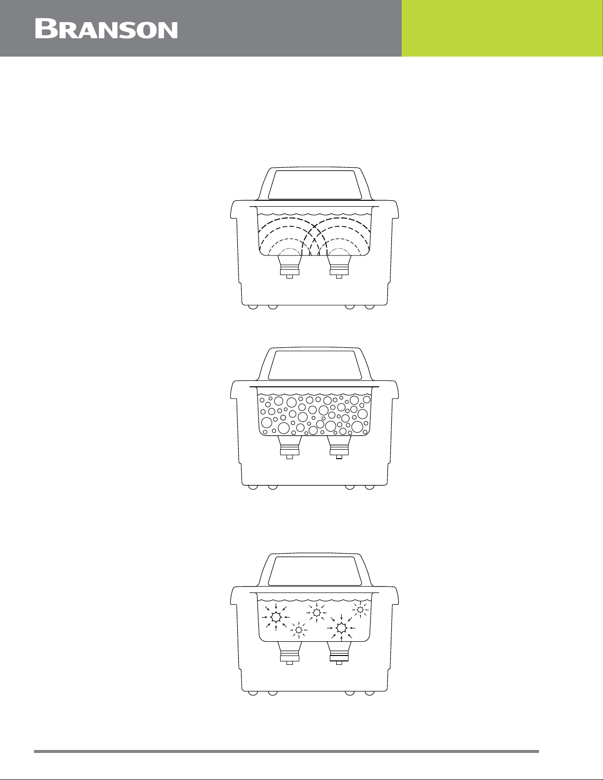
• As the sound waves from the transducer radiate through the solution in the tank, they cause
alternating high and low pressures in the solution
• During the low pressure stage, millions of microscopic bubbles form and grow. This process is
called CAVITATION, meaning “formation of cavities”
• During the high pressure stage, the bubbles collapse, or “implode” releasing enormous amounts
of energy
• For ultrasonic cleaning applications, these implosions act like an army of tiny scrub brushes. They
work in all directions, attacking every surface and invading all recesses and openings
• This same energy can be used for other applications, such as liquid dissolving, homogenizations,
and degassing
8 100-214-294 REV. 05
Page 19
2.2 Ultrasonic Baths
This line of ultrasonic baths include five sizes:
Table 2.1 Ultrasonic Baths Available
Model Number Tank Capacity
1800 1/2 gal. (1.91 l)
2800 3/4 gal. (2.81 l)
3800 1-1/2 gal. (5.71 l)
5800 2-1/2 gal. (9.51 l)
8800 5-1/2 gal. (20.81 l)
Each model is constructed using durable industrial style 40 kHz transducers. These
provide increased ultrasonic power along with built in sweep frequency to ensure uniform
ultrasonic activity throughout the bath. Models 1800 and 2800 have a molded dip in the
left side of their rims to facilitate emptying of solution from the tank. Models 3800, 5800
and 8800 have built in drains and are supplied with tank drain kits. Each model can be
purchased in four different configurations:
• With a Mechanical Timer (M);
• With a Mechanical Timer plus Heat (MH);
• With Digital Control and Timer (CPX);
• With Digital Control, plus Heat and Timer (CPXH).
When you first fill your unit, or refill it with fresh solution, use warm water for the solution.
Turn on the heater (if available), turn on the ultrasonics (press the Sonics key or rotate
the Timer), add the cover and the solution will heat quickly to temperature.
100-214-294 REV. 05 9
Page 20
2.2.1 Accessories For Your Unit
As parts cannot be placed on the tank bottom, accessories include beaker positioning
covers, solid and perforated insert trays, mesh baskets, beakers, and support racks.
NOTICE
Tank covers are included with every unit.
10 100-214-294 REV. 05
Page 21

Chapter 3: Delivery and Handling
3.1 Unpacking Your Unit. . . . . . . . . . . . . . . . . . . . . . . . . . . . . . . . . . . . . . 12
100-214-294 REV. 05 11
Page 22

3.1 Unpacking Your Unit
Please check your unit and its carton carefully for any external or internal damage. If you
find damage, contact your shipping carrier immediately, before contacting your distributor .
Please retain your packaging for future use.
12 100-214-294 REV. 05
Page 23

Chapter 4: Technical Specifications
4.1 Model Name Definition . . . . . . . . . . . . . . . . . . . . . . . . . . . . . . . . . . . . 14
4.2 Equipment Specifications . . . . . . . . . . . . . . . . . . . . . . . . . . . . . . . . . . 15
4.3 Temperature. . . . . . . . . . . . . . . . . . . . . . . . . . . . . . . . . . . . . . . . . . . . 21
4.4 Cleaning Solutions . . . . . . . . . . . . . . . . . . . . . . . . . . . . . . . . . . . . . . . 22
4.5 Solution Effect on Metals . . . . . . . . . . . . . . . . . . . . . . . . . . . . . . . . . . 24
100-214-294 REV. 05 13
Page 24
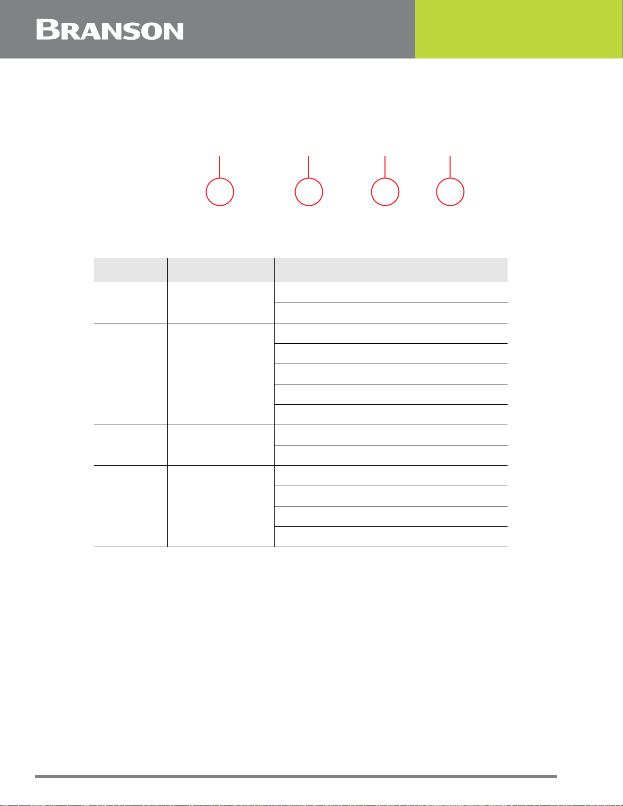
4.1 Model Name Definition
The name of the models determine the specifications of each unit. For example the
CPX1800H-E:
CPX 1800 H - E
1 2 3 4
Table 4.1 Model Name Definition
Item Stands For Availability
CPX: Digital
1 Model
M: Mechanical
1800: 1/2 gal (1.91 l)
2800: 3/4 gal (2.81 l)
2 Tank Capacity
3 Heater
4 Region/voltage
• All models have a frequency of 40 kHz
• In CPXH models, the temperature readout accuracy is ± 3° C (± 5.4° F)
• Models available for 120 V ± 10%, 50/60 Hz and 220 V ± 10%, 50/60 Hz operation
• All 120 V units have CSA/UL or equivalent approval and comply with FCC regulations
• All 220-230 V units meet CE standards
• All units have a ground leakage current less than .50 ma
• Operating ambient temperature is from 5° C to 40° C (41° F to 104° F)
3800: 1-1/2 gal (5.71 l)
5800: 2-1/2 gal (9.51 l)
8800: 5-1/2 gal (20.81 l)
Blank: No heater
H: Heater
Blank: North America (120 VAC)
E: Europe (230 VAC)
J: Japan (100 VAC)
C: China (220 VAC)
14 100-214-294 REV. 05
Page 25

4.2 Equipment Specifications
Table 4.2 Equipment Specifications for North America Models
Model
Name
M1800
M1800H 70 60 150
CPX1800H 70 60 150
CPX1800 70 0 90
M2800
M2800H 110 90 250
CPX2800H 110 90 250
CPX2800 110 0 250
M3800
M3800H 110 180 350
CPX3800H 110 180 350
CPX3800 110 0 130
Tank
Capacity
1/2 gal.
(1.91 l)
3/4 gal
(2.81 l)
1-1/2 gal
(5.71 l)
Tank
Size
(Inches)
L: 9.9
W: 5.5
H:4
L: 9.5
W: 5.5
H: 4
L: 11.5
W: 6
H:6
Overall
Size
(inches)
L: 9.9
W: 12
H: 11.9
L: 13.3
W: 12
H: 11.9
L: 15.6
W: 12.5
H: 14.8
Weight
9 lb
(4 kg)
10 lb
(4.5 kg)
14 lb
(6.4 kg)
Max
Sonics
Power
70 0 90
110 0 130
110 0 130
Heater
Power
Max.
Draw
Power
Req.
M5800
M5800H 160 280 490
CPX5800H 160 280 490
CPX5800 160 0 180
M8800
M8800H 280 560 930
CPX8800H 280 560 930
CPX8800 280 0 320
2-1/2 gal
(9.51 l)
5-1/2 gal
(20.81 l)
L: 11.5
W: 9.5
H: 6
L: 19.5
W: 11.5
H: 15.4
L: 15.6
W: 15.8
H: 14.9
L: 23.5
W: 18.3
H: 15.4
16 lb
(7.3 kg)
28 lb
(12.7 kg)
160 0 180
280 0 320
100-214-294 REV. 05 15
Page 26

Table 4.3 Equipment Specifications for Europe Models
Model
Name
Tank
Capacity
Tank
Size
(mm)
M1800-E
L: 150
M1800H-E 70 60 150
1.91 l
W: 140
CPX1800H-E 70 60 150
(1/2 gal)
H: 100
Overall
Size
(mm)
L:251
W: 305
H: 302
Weight
5.4 kg
(12 lb)
Max
Sonics
Power
Heater
Power
70 0 90
Max.
Draw
Power
Req.
CPX1800-E 70 0 90
M2800-E
M2800H-E 110 110 250
2.81 l
W: 140
L: 240
CPX2800H-E 110 110 250
(3/4 gal)
H: 100
L: 338
W: 305
H: 302
6.8 kg
(15 lb)
110 0 130
CPX2800-E 110 0 250
M3800-E
M3800H-E 110 215 350
5.71 l
W: 150
L: 290
CPX3800H-E 110 215 350
(1-1/2 gal)
H: 150
L: 396
8.2 kg
W: 318
(18 lb)
H: 302
110 0 130
CPX3800-E 110 0 350
M5800-E
M5800H-E 160 300 490
9.51 l
W: 240
L: 290
CPX5800H-E 160 300 490
(2-1/2 gal)
H: 150
L: 396
W: 401
H: 378
9.5 kg
(21 lb)
160 0 180
CPX5800-E 160 0 180
M8800-E
M8800H-E 280 600 930
20.81 l
W: 290
L: 495
CPX8800H-E 280 600 930
(5-1/2 gal)
H: 150
L: 597
W: 465
H: 391
16.3 kg
(36 lb)
280 0 320
CPX8800-E 280 0 320
16 100-214-294 REV. 05
Page 27

Table 4.4 Equipment Specifications for Japan Models
Model
Name
Tank
Capacity
Tank
Size
(inches)
M1800-J
L: 150
M1800H-J 70 45 135
1.91 l
W: 140
CPX1800H-J 70 45 140
(1/2 gal)
H: 100
Overall
Size
(inches)
L: 251
W: 305
H: 302
Weight
4 kg
(9 lb)
Max
Sonics
Power
Heater
Power
70 0 90
Max.
Draw
Power
Req.
CPX1800-J 70 0 90
M2800-J
M2800H-J 110 65 205
2.81 l
W: 140
L: 240
CPX2800H-J 110 65 205
(3/4 gal)
H: 100
L: 338
4.5 kg
W: 305
(10 lb)
H: 302
110 0 130
CPX2800-J 10 0 130
M3800-J
M3800H-J 110 130 275
5.71 l
W: 150
L: 290
CPX3800H-J 110 130 280
(1-1/2 gal)
H: 150
L: 396
6.4 kg
W: 318
(14 lb)
H: 376
110 0 130
CPX3800-J 110 0 130
M5800-J
M5800H-J 160 200 405
9.5 l
W: 240
L: 290
CPX5800H-J 160 200 410
(2-1/2 gal)
H: 150
L: 396
7.3 kg
W: 401
(16 lb)
H: 378
160 0 180
CPX5800-J 160 0 180
M8800-J
M8800H-J 280 400 755
20.81 l
W: 290
L: 495
CPX8800H-J 280 400 760
(5-1/2 gal)
H: 150
L: 597
12.7 kg
W: 465
(28 lb)
H: 391
280 0 320
CPX8800-J 280 0 320
100-214-294 REV. 05 17
Page 28

Table 4.5 Equipment Specifications for China Models
Model
Name
M1800-C
M1800H-C
CPX1800H-C
CPX1800-C
M2800-C
M2800H-C
CPX2800H-C
CPX2800-C
M3800-C
M3800H-C
CPX3800H-C
CPX3800-C
Tank
Capacity
1.91 l
(1/2 gal)
2.81 l
(3/4 gal)
5.71 l
(1-1/2 gal)
Tank
Size
(inches)
L: 150
W: 140
H: 100
L: 240
W: 140
H: 100
L: 290
W: 150
H: 150
Overall
Size
(inches)
L: 251
W: 305
H: 302
L: 338
W: 305
H: 302
L: 396
W: 318
H: 376
Weight
5.4 kg
(12 lb)
6.8 kg
(15 lb)
8.2 kg
(18 lb)
Max
Sonics
Power
Heater
Power
Max.
Draw
Power
Req.
70 0 90
70 55 145
70 55 145
70 0 90
110 0 130
110 105 250
110 105 250
110 0 130
110 0 130
110 205 350
110 205 350
110 0 130
M5800-C
M5800H-C
CPX5800H-C
CPX5800-C
M8800-C
M8800H-C
CPX8800H-C
CPX8800-C
9.5 l
(2-1/2 gal)
20.81 l
(5-1/2 gal)
L: 290
W: 240
H: 150
L: 495
W: 290
H: 150
L: 396
W: 401
H: 378
L: 597
W: 465
H: 391
9.5 kg
(21 lb)
16.3 kg
(36 lb)
160 0 180
160 285 490
160 285 490
160 0 180
280 0 320
280 560 930
280 560 930
280 0 320
18 100-214-294 REV. 05
Page 29

Table 4.6 Fuse Table for North America and Japan Models
Model Name Fuse 1 Fuse 2 Fuse 3
M1800 / M1800-J
M1800H / M1800H-J
250 V, 2A
CPX1800H / CPX1800H-J
CPX1800 / CPX1800-J 250 V, 1.6A
M2800 / M2800-J
250 V, 2.5AM2800H / M2800H-J
250 V, 1.6A
CPX2800H / CPX2800H-J
CPX2800 / CPX2800-J 250 V, 1.6A
M3800 / M3800-J
250 V, 2.5AM3800H / M3800H-J
CPX3800H / CPX3800H-J
CPX3800 / CPX3800-J 250 V, 1.6A
M5800 / M5800-J
250 V, 5A 250 V, 2AM5800H / M5800H-J
CPX5800H / CPX5800H-J
CPX5800 / CPX5800-J 250 V, 2.5A 250 V, 2.5A
250 V, 1A
M8800 / M8800-J
M8800H / M8800H-J
250 V, 10A
CPX8800H / CPX8800H-J
CPX8800 / CPX8800-J 250 V, 5A
250 V, 3.15A
100-214-294 REV. 05 19
Page 30

Table 4.7 Fuse Table for Europe and China Models
Model Name Fuse 1 Fuse 2 Fuse 3
M1800-E / M1800-C
M1800H-E / M1800H-C
250 V, 1.6A
CPX1800H-E / CPX1800H-C
CPX1800-E / CPX1800-C
M2800-E / M2800-C
250 V, 2.5AM2800-E / M2800H-C
CPX2800H-E / CPX2800H-C
CPX2800-E / CPX2800-C 250 V, 1.6A
M3800-E / M3800-C
250 V, 2.5AM3800H-E / M3800H-C
CPX3800H / CPX3800H-C
CPX3800-E / CPX3800-C 250 V, 1.6A
M5800-E / M5800-C
250 V, 1.6A
250 V, 1A
250 V, 5A 250 V, 2AM5800H-E / M5800H-C
CPX5800H-E / CPX5800H-C
CPX5800-E / CPX5800-C 250 V, 1.6A 250 V, 1.6A
M8800-E / M8800-C
M8800H-E / M8800H-C
250 V, 5A
250 V, 2A
CPX8800H-E / CPX8800H-C
CPX8800-E / CPX8800-C 250 V, 2.5A
20 100-214-294 REV. 05
Page 31

4.3 Temperature
Table 4.8 Temperature
Item
Heater
Solution
Over
Temperature
Protection
(CPXH only)
The heater may cause some discoloration of the tank. This is normal
and will not affect the performance of the unit.
The fastest method to heat your ultrasonic bath is to fill with warm
solution, use heat, ultrasonics (which also adds heat), and a cover.
If Max Temperature of 75° C is reached, Ultrasonics will pause for a
period of time until the temperature in the bath falls back down to 69° C
(the max set point). Once the temperature falls back down to 69° C,
Ultrasonics will resume. This will apply for both continuous/infinity
mode, as well as timed mode. In timed mode, the timer will pause while
Ultrasonics is off, and will resume once Ultrasonics resumes.
100-214-294 REV. 05 21
Page 32

4.4 Cleaning Solutions
CAUTION General Warning
Do not use alcohol, gasoline, bleach, mineral acids, solutions with a
flash point, semi-aqueous or combustible liquids in ultrasonic tanks,
or you will void the warranty. Only use non-flammable solutions and
water-based solutions.
4.4.1 Solution Types
Water-based solutions can be either slightly acidic or alkaline. They include detergents,
soaps and industrial cleaners designed to remove specific soils.
Acidic water-based solutions: remove rust, tarnish or scale. They range from mild
solutions that remove tarnish, to concentrated, inhibited acidic solutions that remove
investment plaster, milk-stone, zinc oxide and rust from steel and cast iron as well as
smut and heat-treat scale from hardened steel.
Alkaline water-based solutions: include carbonates, silicates and caustics. These
cause emulsifying action, which keeps soil from redepositing on the cleaned surface, and
improves cleaning action in hard water.
Table 4.9 Alkaline Solution Strength and Uses
Alkaline Strength Removes
Mild Light oils and greases, cutting oils and coolant compounds.
Mild to Strong
Heavy-duty Mill scale, heat-treat scale, corrosion or oxides.
Change the cleaning solution periodically. Cleaning solutions can become contaminated
with suspended soil particles which coat the tank bottom. This coating dampens the
ultrasonic action and reduces cleaning efficiency. Certain solutions will cavitate better than
others. Contact your local distributor for further information.
Heat and cavitation increase the chemical activity of cleaning solutions. Some materials
may be damaged by this stronger chemical action. When in doubt, test run samples of
items to be cleaned.
Caustic solutions: used to remove rust from steels, metal alloy corrosion and a variety
of tenacious soils.
4.4.2 Solution Amounts
Solution amounts may vary. The amount you use depends on the detergent and the type
of soil to be removed. Follow instructions on the solution container and refer to the table
below for the effects of solutions on metals.
Heavy grease and oils, waxes, vegetable oils, inks, wax or fatbase buffing and polishing compounds, milk residues and
carbohydrates.
22 100-214-294 REV. 05
Page 33

4.4.3 Chemicals Harmful to Your Tank
The following chemicals will harm your ultrasonic tank and the action of ultrasonics and
higher operating temperatures will increase their chemical activity. Do not use these or
similar chemicals directly or in dilution in your ultrasonic tank or you will void your
warranty.
Table 4.10 Chemicals Harmful to Your Tank
Harmful Chemicals
Acetophenone Chloracetic Acid Hydrocyanic Acid
Aluminum Chloride Chloric Acid Hydrofluoric Acid
Aluminum Flouride Chlorine, Anhydrous Hydroflousilicic Acid
Aluminum Sulphate Chromic Acid Iodoform
Ammonium Bifluoride Copper Chloride Mercuric Chloride
Ammonium Chloride Copper Fluoborate Muriatic Acid
Ammonium Hydroxide Ethyl Chloride Phosphoric (crude)
Amyl Chloride Ferric Chloride Sodium Hypochlorite
Antimony Trichloride Ferrous Chloride Potassium Chloride
Aqua Regia Ferris Sulfate Stannic Chloride
Bromine Fluoboric Acid Stannous Chloride
Calcium Bisulfate Fluorine Sulfur Chloride
Calcium Bisulfite Hydrobromic Acid Sulfuric Acid
Calcium Hypochloride Hydrochloric Acid Zinc Chloride
100-214-294 REV. 05 23
Page 34

4.5 Solution Effect on Metals
Table 4.11 Solution Effects on Metals
Cleaning
Agent
Steel Brass
Aluminum
Magnesium
Zinc
S.
Steel
Copper
Tin
Optical (1) none none none none** none** none none**
Jewelry (1)
Buffing (1)
Compound
Oxide (2)
remover
Electronic
cleaner (1)
General (1)
purpose
Industrial
strength (1)
Metal (1)
cleaner 1
Metal (1)
cleaner 2
none none none none none none none
none
slight
etch
none none
none none
none none
slight
stain
none
none none attacks none none
slight
attack
slight
attack
slight
attack
slight
attack
attacks attacks none none
none none none none
none none none none
none none none none
none none none none none none none
none none
slight
attack
none none none none
Metal (1)
cleaner 3
Liquid rust
(3) stripper
GP (1)
Powder
none none none none none none none
none none
attacks*** attacks***
attacks none
none none none none none none none
* Contact distributor for cleaning agent availability outside the US.
** No effect if solution temperature is less than 60° C (140° F).
(1) = Alkaline; (2) = Acidic; and (3) = Caustic.
WARNING General Warning
*** Free hydrogen may be released if solution comes in contact with
reactive metals.
slight
attack
24 100-214-294 REV. 05
Page 35

Chapter 5: Installation and Setup
5.1 Installing Your Unit . . . . . . . . . . . . . . . . . . . . . . . . . . . . . . . . . . . . . . 28
100-214-294 REV. 05 27
Page 36

5.1 Installing Your Unit
Check the plate on the back of the unit for correct power requirements. Position your unit
within easy reach of a standard grounded electrical outlet. Do not place the unit on a
circuit which could become overloaded. If your unit does not operate correctly, first refer
to 7.2 Troubleshooting for possible causes, or contact an authorized service center listed
at the end of this manual for additional information.
28 100-214-294 REV. 05
Page 37

Chapter 6: Operation
6.1 Operating Your Ultrasonic Bath . . . . . . . . . . . . . . . . . . . . . . . . . . . . . 30
6.2 M Series . . . . . . . . . . . . . . . . . . . . . . . . . . . . . . . . . . . . . . . . . . . . . . . 31
6.3 MH Series . . . . . . . . . . . . . . . . . . . . . . . . . . . . . . . . . . . . . . . . . . . . . . 34
6.4 CPX Series . . . . . . . . . . . . . . . . . . . . . . . . . . . . . . . . . . . . . . . . . . . . . 37
6.5 CPXH Series . . . . . . . . . . . . . . . . . . . . . . . . . . . . . . . . . . . . . . . . . . . . 42
6.6 Cleaning Methods . . . . . . . . . . . . . . . . . . . . . . . . . . . . . . . . . . . . . . . . 57
100-214-294 REV. 05 29
Page 38

6.1 Operating Your Ultrasonic Bath
If this is the first time you are using the ultrasonic bath, please read this whole section
before operating your unit.
30 100-214-294 REV. 05
Page 39

6.2 M Series
CAUTION General Warning
Table 6.1 Before you Begin
Step Action
1 Select your cleaning solution (refer to 4.5 Solution Effect on Metals).
2
• Do not place parts or containers directly on the bottom of the tanks; use a
tray or wire to suspend items. Direct placement can cause the units to fail
• Do not allow the solution to drop more than 3/8 inch (1 cm) below the
operating level line with ultrasonics on
• Do not ever use alcohol, gasoline or flammable solutions. Doing so could
cause a fire or explosion. Use only water-based solutions
• Do not ever use mineral acids. These could damage the tank
Failure to comply with these cautions will void your warranty.
Allowing for the volume of the parts you will be cleaning and leaving room
for cleaning solution, fill the tank with warm tap water to the operating
level line.
3 Add cleaning solution to the tank water.
4 Plug the unit into a grounded outlet.
5
For maximum efficiency, refer to 7.1 Optimizing Your Ultrasonic Bath”,
before proceeding.
NOTICE
If this is the first time you are running the unit, or if you have
changed cleaning solution, you must degas the solution. If not, skip
to 6.2.3 Cleaning Items (Treating Samples).”
100-214-294 REV. 05 31
Page 40

6.2.1 M Series Explanation of Controls
Figure 6.1 M Series Controls
Table 6.2 M Series Explanation of Controls
Control Function
This switch is located on the back of the unit, next to the power
cord receptacle.
• Press the on side to power on the unit
Main Power Switch
• Press the off side to power off the unit
Timer Knob
6.2.2 Degassing
For initial cleaning solution degassing.
Table 6.3 For initial cleaning solution degassing.
Step Action
1 Turn Main Power switch on.
2
When operating the unit, normally leave the Main Power switch
in the on position, and use the Timer Knob to activate
ultrasonics.
Activates ultrasonics and sets time.
• Turn clockwise for timed operation (0–60 minutes)
• Turn counterclockwise to the HOLD position for continuous
operation
• Turn to the zero position to turn unit Off
Turn the Timer Knob clockwise to 5–10 and let the unit run to allow the
solution to “degas”.
NOTICE
Refer to 6.5.11 Solution for information on degassing.
32 100-214-294 REV. 05
Page 41

6.2.3 Cleaning Items (Treating Samples)
NOTICE
To stop ultrasonics at any time, turn the Timer Knob to the zero
position.
Table 6.4 Treating Samples
Step Action
1 Turn Main Power switch on.
Turn the Timer Knob clockwise to set the amount of time (0 - 60 minutes)
2
you wish the items to be cleaned. Turn the Timer Knob counterclockwise to
the Hold position for continuous operation.
3
4
5
6 When items are clean, slowly remove them from the tank.
7 Rinse the clean items with clean water and dry them, if necessary.
Place the items into a basket, perforated tray, or beakers in a positioning
cover.
If using beakers or a solid tray, add cleaning solution to beakers or tray to
cover the items.
Slowly lower the tray or beakers into the tank. Do not allow items to
contact the tank bottom.
100-214-294 REV. 05 33
Page 42

6.3 MH Series
CAUTION General Warning
Table 6.5 Before you Begin
Step Action
1 Select your cleaning solution (refer to 4.5 Solution Effect on Metals).
Allowing for the volume of the parts you will be cleaning and leaving room
2
for cleaning solution, fill the tank with warm tap water to the operating
level line.
• Do not place parts or containers directly on the bottom of the tanks; use a
tray or wire to suspend items. Direct placement can cause the units to fail
• Do not allow the solution to drop more than 3/8 inch (1 cm) below the
operating level line with heat or ultrasonics on
• Do not ever use alcohol, gasoline or flammable solutions. Doing so could
cause a fire or explosion. Use only water-based solutions
• Do not ever use mineral acids. These could damage the tank
Failure to comply with these cautions will void your warranty.
3 Add cleaning solution to the tank water.
4 Plug the unit into a grounded outlet.
5
For maximum efficiency, refer to 7.1 Optimizing Your Ultrasonic Bath,
before proceeding.
NOTICE
If this is the first time you are running the unit, or if you have
changed cleaning solution, you must degas the solution. If not, skip
to 6.3.3 Cleaning Items (Treating Samples).”
34 100-214-294 REV. 05
Page 43

6.3.1 MH Series Explanation of Controls
Figure 6.2 MH Series Controls
Table 6.6 MH Series Explanation of Controls
Control Function
This switch is located on the back of the unit, next to the power
cord receptacle.
Main Power
Switch
Heat Switch
Timer Knob
6.3.2 Degassing
Table 6.7 For initial cleaning solution degassing.
Step Action
1 Turn Main Power switch on.
• Press the on side to power on the unit
• Press the off side to power off the unit
When operating the unit, normally leave the Main Power switch in
the (on) position, and use the Timer Knob to activate ultrasonics.
Activates heat to 60° C (140° F) maximum.
NOTICE
Refer to 4.3 Temperature for further information on temperature.
Activates ultrasonics and sets time.
• Turn clockwise for timed operation (0–60 minutes)
• Turn counterclockwise to the HOLD position for continuous operation
Turn to the zero position to turn unit Off.
2 Turn Heat switch on.
Turn the Timer Knob clockwise to 5–10 and let the unit run to allow the
solution to “degas”.
3
NOTICE
Refer to 6.5.11 Solution for information on degassing.
100-214-294 REV. 05 35
Page 44

6.3.3 Cleaning Items (Treating Samples)
NOTICE
To stop ultrasonics at any time, turn the Timer Knob to the zero
position.
Table 6.8 Treating Samples
Step Action
1 Turn Main Power switch on.
Turn the Timer Knob clockwise to set the amount of time (0–60 minutes)
2
you wish the items to be cleaned. Turn the Timer Knob counterclockwise
to the HOLD position for continuous operation.
3
4
5
6 When items are clean, slowly remove them from the tank.
7 Rinse the clean items with clean water and dry them, if necessary.
Place the items into a basket, perforated tray, or beakers in a positioning
cover.
If using beakers or a solid tray, add cleaning solution to beakers or tray
to cover the items.
Slowly lower the tray or beakers into the tank. Do not allow items to
contact the tank bottom.
36 100-214-294 REV. 05
Page 45

6.4 CPX Series
CAUTION General Warning
Table 6.9 Before you begin
Step Action
1 Select your cleaning solution (refer to 4.5 Solution Effect on Metals).
Allowing for the volume of the parts you will be cleaning and leaving
2
room for cleaning solution, fill the tank with warm tap water to the
operating level line.
• Do not place parts or containers directly on the bottom of the tanks; use a
tray or wire to suspend items. Direct placement can cause the units to fail
• Do not allow the solution to drop more than 3/8 inch (1 cm) below the
operating level line with ultrasonics on
• Do not ever use alcohol, gasoline or flammable solutions. Doing so could
cause a fire or explosion. Use only water-based solutions
• Do not ever use mineral acids. These could damage the tank
Failure to comply with these cautions will void your warranty.
3 Add cleaning solution to the tank water.
4 Plug the unit into a grounded outlet.
5
For maximum efficiency, refer to 7.1 Optimizing Your Ultrasonic Bath,
before proceeding.
NOTICE
If this is the first time you are running the unit, or if you have
changed cleaning solution, you must degas the solution. If not, skip
to 6.4.4 Cleaning Items (Treating Samples).”
100-214-294 REV. 05 37
Page 46

6.4.1 CPX Explanation of Controls
Figure 6.3 CPX Series Controls
Table 6.10 CPX Series explanation of controls
Control Function
This switch is located on the back of the unit, next to the power cord
receptacle.
Main Power
Switch
• Press the on side to power on the unit
• Press the off side to power off the unit
When operating the unit, normally leave the Main Power switch in the on
position, and use the On/Standby key to switch between the operating
state and standby state.
On/Standby
When the Main Power switch on the rear panel is in the on position, press
to power on/off the unit.
Up/Down Keys
Press to increase/decrease ultrasonic or degassing cycle time (hold for
quick increments/decrements).
Time values are circular, pressing Up from 99 minutes takes you to
Constant Sonics Mode (Constant Sonics icon and “- -” display on the
LCD) and then to 1 minutes. Pressing Down from 1 minutes takes you to
Constant Sonics Mode and then to 99 minutes.
During power-up, use to select high or low ultrasonic power output.
38 100-214-294 REV. 05
Page 47

Table 6.10 CPX Series explanation of controls
Control Function
Sonics
Press to activate ultrasonics. If running in Timed Mode, a timer will begin
to count down and ultrasonics will stop at 0 minutes. In Constant Sonics
Mode (Constant sonics icon and “- -” on the display), timer has no
function.
Press sonics key again to deactivate ultrasonics.
If running in Timed Mode, press Up and Down keys to adjust the
ultrasonic cycle time (adjustable from 1 to 99 minutes).
Degas
Press to degas the solution or to run a degas application. A default timer
of 5 minutes will begin to count down and degassing will stop at 0
minutes.
Press Degas key again to stop degassing the solution.
During a degas cycle, press Up and Down keys to adjust the degas cycle
time (adjustable from 1 to 99 minutes).
NOTICE
Refer to 6.5.11 Solution for information on degassing.
6.4.2 CPX Series LCD Description
Table 6.11 CPX Series LCD description.
Reference Function
Power Level
Displayed for 15 s only during power-up, shows the current ultrasonic
output power selection.
Press the Sonics or Degas key to go into normal operating mode.
Press Up or Down keys to change between high (HI) and low (LO)
power ultrasonics.
Sonics/Degas Timer
Displays the duration of a timed ultrasonic or degas cycle.
Press Up and Down keys to adjust ultrasonic or degassing cycle time
(adjustable from 1 to 99 minutes).
In Constant Sonics Mode, “- -” is displayed.
Constant Sonics
Indicates the unit is operating in Constant Sonics Mode.
In Constant Sonics Mode, sonics will remain on until the Sonics key is
pressed or the unit is turned off.
100-214-294 REV. 05 39
Page 48

Table 6.11 CPX Series LCD description.
Reference Function
Sonics On
Indicates sonics are active.
If running in Timed Mode, ultrasonics will remain on until the timer
reaches 0 minutes.
In Constant Sonics Mode, ultrasonics will remain on until the Sonics
key is pressed or the unit is turned off.
Degas On
Indicates the unit is in Degas Mode.
In Degas Mode, degassing will continue until the timer reaches 0
minutes.
NOTICE
Refer to 6.5.11 Solution for information on degassing.
Alarm
Alarm Bell icon flashes when the unit encounters an abnormal
operating condition.
6.4.3 Degassing
For initial cleaning solution degassing.
NOTICE
Table 6.12 Degassing your CPX Series unit
Step Action
1 Turn Main Power switch on.
2 Press the On/Standby key to turn on the unit.
NOTICE
Refer to 7.2 Troubleshooting for information on troubleshooting.
To stop degassing at any time, press the Degas key.
Press Degas key once to start the degas process.
Default degas time is 5 minutes.
3
If necessary, use Up/Down keys to alter degas time during a degas cycle.
NOTICE
Refer to 6.5.11 Solution for information on degassing.
40 100-214-294 REV. 05
Page 49

Table 6.12 Degassing your CPX Series unit
Step Action
4
After completing the degas time, you are ready to set operating
parameters.
6.4.4 Cleaning Items (Treating Samples)
NOTICE
To stop ultrasonics at any time, press the Sonics key.
Table 6.13 Treating Samples
Step Action
1 Turn Main Power switch on.
2 Press the On/Standby key to turn on the unit.
Set the amount of time you wish the items to be cleaned, or select
Constant Sonics Mode:
3
• Use Up/Down keys to increase/decrease cycle time (hold for quick increments/
decrements)
• Pressing Up key from 99 minutes or Down key from 1 minutes takes you to
Constant Sonics Mode (Constant Sonics icon and “- -” display on the LCD
screen)
4 Press the Sonics key to activate ultrasonics.
5
6
7
Place the items into a basket, perforated tray, or beakers in a positioning
cover.
If using beakers or a solid tray, add cleaning solutions to beakers or tray
to cover the items.
Slowly lower the tray or beakers into the tank. Do not allow items to
contact the tank bottom.
8 When items are clean, slowly remove them from the tank.
9 Rinse clean items with clean, warm water and dry, if necessary.
100-214-294 REV. 05 41
Page 50

6.5 CPXH Series
CAUTION General Warning
Table 6.14 Before you begin.
Step Action
1 Select your cleaning solution (refer to 4.5 Solution Effect on Metals).
Allowing for the volume of the parts you will be cleaning and leaving
2
room for cleaning solution, fill the tank with warm tap water to the
operating level line.
• Do not place parts or containers directly on the bottom of the tanks; use a
tray or wire to suspend items. Direct placement can cause the units to fail
• Do not allow the solution to drop more than 3/8 inch (1 cm) below the
operating level line with heat or ultrasonics on
• Do not ever use alcohol, gasoline or flammable solutions. Doing so could
cause a fire or explosion. Use only water-based solutions
• Do not ever use mineral acids. These could damage the tank
Failure to comply with these cautions will void your warranty.
3 Add cleaning solution to the tank water.
4 Plug the unit into a grounded outlet.
5
For maximum efficiency, refer to 7.1 Optimizing Your Ultrasonic Bath”,
before proceeding.
NOTICE
If this is the first time you are running the unit, or if you have
changed cleaning solution, you must degas the solution. If not, skip
to 6.5.5 Cleaning Items (Treating Samples) in Timed Sonics Mode.”
42 100-214-294 REV. 05
Page 51

6.5.1 CPXH Series Explanation of Controls
Figure 6.4 CPXH Series Controls
Table 6.15 CPXH Series explanation of controls.
Control Function
This switch is located on the back of the unit, next to the power cord
Main
Power
Switch
receptacle.
• Press the on side to power on the unit
• Press the off side to power off the unit. When operating the unit, normally leave
the Main Power switch in the on position, and use the On/Standby key to switch
between the operating state and standby state
On/Standby
When the Main Power switch on the rear panel is in the on position, press
to power on/off the unit.
Up/Down Keys
Press to increase/decrease ultrasonic or degassing cycle time (hold for
quick increments/decrements).
Time values are circular, pressing Up key from 99 minutes takes you to 1
minutes. Pressing Down key from 1 minutes takes you to 99 minutes.
If the Fn key was pressed, use the Up/Down keys to adjust function
settings.
Heat
Press to turn heater on/off.
Heater will shut off when set temperature is attained.
100-214-294 REV. 05 43
Page 52

Table 6.15 CPXH Series explanation of controls.
Control Function
Sonics
Press to activate ultrasonics. If running in Timed Mode, a timer will begin to
count down and ultrasonics will stop at 0 minutes. In Constant Sonics Mode
(Constant Sonics icon and “- - -” on the display), timer has no function.
Press Sonics key again to deactivate ultrasonics.
If running in Timed Mode, press Up and Down keys to adjust the ultrasonic
cycle time (adjustable from 1 to 99 minutes).
Degas
Press to degas the solution or to run a degas application. The degas timer
will begin to count down from its current setting and degassing will stop at
0 minutes.
Press Degas key again to stop degassing the solution.
During a degas cycle, press Up and Down keys to adjust degas time
(adjustable from 1 to 99 minutes).
NOTICE
Refer to 6.5.11 Solution for information on degassing.
Auto
Press to begin an auto cycle. In Auto Mode, the following actions are
carried out automatically by the controller:
• Heater is turned on to bring bath to set temperature
• When set temperature is reached, ultrasonics are activated. The unit will abort
the auto cycle and flash the AUTO icon if set temperature is not reached within a
120-minute period
• When ultrasonics timer reaches 0 minutes, the auto cycle is finished
If at any point during an auto cycle the degas key is pressed, a degas cycle
will begin. If ultrasonics has already started, the ultrasonics timer will
restart after the degas period.
44 100-214-294 REV. 05
Page 53

Table 6.15 CPXH Series explanation of controls.
Control Function
Press the Fn key to access less-frequently used function.
• Press 1x to Set Target Temp
• Press 2x to Set Constant Sonics
• Press 3x to Set Power Level
• Press 4x Sel. Temp Units
• Press 5x to Set Degas Time
• Press 6x Ready State (Set Sonics Time)
The appropriate icon will flash to indicate which option is selected.
If no key is pressed after 15 seconds the unit will save any changes and
return to the Ready state.
Press the Fn key again after making any changes to scroll through the rest
of the options and return to the Ready state.
The following options are available:
• Set Temperature (Fn 1x): Press Up and Down keys to increase/decrease the
bath set temperature
Fn
(1x)
Indicates
Blinking
• Timed/Constant Sonics (Fn 2x): Press Up key to select Constant Sonics Mode
(Constant Sonics icon and “- - -” on the display)
Press down key to select Timed Sonics Mode
Fn
(2x)
Indicates
Blinking
100-214-294 REV. 05 45
Page 54

Table 6.15 CPXH Series explanation of controls.
Control Function
• Full/Low Power (Fn 3x): Press up key to select full power ultrasonic output.
Press down key to select low power ultrasonic output
Fn
• Temperature Units (Fn 4x): Press key to select Fahrenheit (°F). Press Down
key to select Celsius (°C)
Fn
(3x)
(4x)
Indicates
Blinking
Indicates
Blinking
• Degas Time (Fn 5x): Press Up/Down keys to increase/decrease degas time
(hold for quick increments/decrements). Time values are circular, pressing Up
from 99 minutes takes you to 1 minute. Pressing Down from 1 minute takes you
to 99 minutes
Fn
46 100-214-294 REV. 05
(5x)
Indicates
Blinking
Page 55

6.5.2 CPXH Series LCD Description
Table 6.16 LCD Description for CPXH Series.
Item Function
Sonics/Degas Set Time
Displays the set time for a timed ultrasonic or degas cycle.
• Press Up and Down keys to adjust ultrasonic or degassing cycle time
(adjustable from 1 to 99 minutes). In Constant Sonics Mode, “- - -” is
displayed
Set Temperature
Displays the target temperature.
Temperature units are indicated by the °F (for Fahrenheit) or °C (for
Celsius) right of the Current Temperature icon.
Current Temperature
Displays the current tank temperature as measured by the unit.
Temperature units are indicated right of the icon as either °F (For
Fahrenheit) or °C (for Celsius). Units can be switched using the Fn key.
See Fn key description on Table 6.15.
Sonics/Degas Timer
Displays the remaining time of a running timed ultrasonic or degas
cycle.
Press up and down keys to adjust ultrasonic or degassing cycle time
(adjustable from 1 to 99 minutes).
Auto
Indicates the unit is in Auto Mode. In Auto Mode, the following actions
are carried out automatically by the controller:
• Heater is turned on to bring bath to set temperature
• When set temperature is reached, ultrasonics are activated. The unit will
abort the auto cycle and flash the icon if set temperature is not reached
within a 120-minute period
• When ultrasonics timer reaches 0 minutes, the auto cycle is finished
If at any point during an auto cycle the degas key is pressed, a degas
cycle will begin. If ultrasonics has already started, the ultrasonics timer
will restart after the degas period.
Constant Sonics
Indicates the unit is operating in Constant Sonics Mode. In Constant
Sonics Mode, ultrasonics will remain on until the Sonics key is pressed
or the unit is turned off.
100-214-294 REV. 05 47
Page 56

Table 6.16 LCD Description for CPXH Series.
Item Function
Heat
Indicates the heater is on. Heater will shut off when set temperature is
attained.
Sonics On
Indicates sonics are active.
If running in Timed Mode, ultrasonics will remain on until the timer
reaches 0 minutes.
In Constant Sonics Mode, ultrasonics will remain on until the Sonics
key is pressed or the unit is turned off.
Degas On
Indicates the unit is in Degas Mode.
In Degas Mode, degassing will continue until the timer reaches 0
minutes.
6.5.3 Degassing
For initial cleaning solution degassing.
NOTICE
NOTICE
Refer to 6.5.11 Solution for information on degassing.
Power Level
Indicates the ultrasonic power output selection:
• Four bars indicate high power ultrasonics
• Two bars indicate low power ultrasonics
Alarm
Alarm Bell icon flashes when the unit encounters an abnormal
operating condition.
NOTICE
Refer to 7.2 Troubleshooting for information on troubleshooting.
To stop degassing at any time, press the Degas key.
48 100-214-294 REV. 05
Page 57

Table 6.17 Degassing
Step Action
1 Turn Main Power switch on.
2 Press the On/Standby key to turn on the unit.
Default degas time is 5 minutes.
3
To change the degas time, press the Fn key until the Degas icon appears
and the Set Time icon flashes. Then press the Up/Down keys to change
the degas time.
Press Degas key once to start the degas process.
4
If necessary, use up/down keys to alter degas time during a degas cycle.
NOTICE
Refer to 6.5.11 Solution for information on degassing.
5
After completing the degas time, you are ready to set operating
parameters.
6.5.4 Ultrasonics Operating Modes
Table 6.18 Ultrasonic Operating Modes
Mode Action
In Timed Sonics Mode, a timer will begin to count down and ultrasonics
Timed
Sonics
will remain on until the timer reaches 0 minutes.
For instructions, see 6.5.5 Cleaning Items (Treating Samples) in Timed
Sonics Mode.
In Constant Sonics Mode ultrasonics will remain on until the Sonics key is
Constant
Sonics
pressed or power is turned off to the unit.
For instructions, see 6.5.6 Cleaning Items (Treating Samples) in
Constant Sonics Mode.
In Auto mode ultrasonics will start once set temperature is attained.
Ultrasonics will remain on until the timer reaches 0 minutes.
Auto
For instructions, see 6.5.7 Cleaning Items (Treating Samples) in Auto
Mode.
100-214-294 REV. 05 49
Page 58

6.5.5 Cleaning Items (Treating Samples) in Timed Sonics Mode
NOTICE
To stop ultrasonics at any time, press the Sonics key.
Table 6.19 Treating samples in Timed Sonics Mode
Step Action
1 Turn Main Power on.
2 Press the On/Standby key to turn on the unit.
3 If necessary, degas the liquid. See 6.5.3 Degassing for instructions.
Set the amount of time you wish the items to be cleaned:
4
Use up/down keys to increase/decrease cycle time (hold for quick
increments/decrements).
Set the tank temperature:
• Press the Fn key until the Set Temperature icon flashes
• Press the Up/Down keys to alter the setting to the tank temperature you wish
5
to reach
• Press the Heat key once to activate heat. The Heat icon appears
NOTICE
Units can be switched between °F or °C using the Fn key. See Fn key
description on 6.5.1 CPXH Series Explanation of Controls.
Set the ultrasonic power level:
6
• Press the Fn key until the Power Level icon flashes
• Press the Up key to select high power ultrasonics or press the Down key to
select low power ultrasonics
7 Press the Sonics key to activate ultrasonics.
8
9
10
Place the items into a basket, perforated tray, or beakers in a positioning
cover.
If using beakers or a solid tray, add cleaning solution to beakers or tray
to cover the items.
Slowly lower the tray or beakers into the tank. Do not allow items to
contact the tank bottom.
11 When items are clean, slowly remove them from the tank.
12 Rinse clean items with clean, warm water and dry, if necessary.
50 100-214-294 REV. 05
Page 59

6.5.6 Cleaning Items (Treating Samples) in Constant Sonics Mode
NOTICE
To stop ultrasonics at any time, press the Sonics key.
Table 6.20 Treating Samples in Constant Sonics Mode
Step Action
1 Turn Main Power switch on.
2 Press the On/Standby key to turn on the unit.
3 If necessary, degas the liquid. See 6.5.3 Degassing for instructions.
Change sonics mode:
4
• Press the Fn key until the Constant Sonics icon and the Set Time icon flash
• Press the Up key to select Constant Sonics Mode
Set the tank temperature:
• Press the Fn key until the Set Temperature icon flashes
• Press the Up/Down keys to alter the setting to the tank temperature you wish
5
to reach
• Press the Heat key once to activate heat. The Heat icon appears
NOTICE
Units can be switched between °F or °C using the Fn key. See Fn key
description on Table 6.15.
Set the ultrasonic power level:
6
• Press the Fn key until the Power Level icon flashes
• Press the Up key to select high power ultrasonics or press the Down key to
select low power ultrasonics
7 Press the Sonics key to activate ultrasonics.
8
9
10
Place the items into a basket, perforated tray, or beakers in a positioning
cover.
If using beakers or a solid tray, add cleaning solution to beakers or tray
to cover the items.
Slowly lower the tray or beakers into the tank. Do not allow items to
contact the tank bottom.
11 When items are clean, slowly remove them from the tank.
12 Rinse clean items with clean, warm water and dry, if necessary.
100-214-294 REV. 05 51
Page 60

6.5.7 Cleaning Items (Treating Samples) in Auto Mode
NOTICE
To stop ultrasonics at any time, press the Sonics key.
Table 6.21 Treating Samples in Auto Mode
Step Action
1 Turn Main Power switch on.
2 Press the On/Standby key to turn on the unit.
3 If necessary, degas the liquid. See 6.5.3 Degassing for instructions.
Set the amount of time you wish the items to be cleaned:
4
• Use Up/Down keys to increase/decrease cycle time (hold for quick
increments/decrements)
5
6
7
8
9
10
Set the tank temperature:
• Press the Fn key until the Set Temperature icon flashes
• Press the Up/Down keys to alter the setting to the tank temperature you wish
to reach
• Press the Heat key once to activate heat. The Heat icon appears
• Units can be switched between °F or °C using the Fn key. See Fn key
description on
6.5.1 CPXH Series Explanation of Controls
Set the ultrasonic power level:
• Press the Fn key until the Power Level icon flashes
• Press the Up key to select high power ultrasonics or press the Down key to
select low power ultrasonics
Press the Auto key to begin Auto Cycle. Heater will turn on and sonics will
start once set temperature is attained.
Place the items into a basket, perforated tray, or beakers in a positioning
cover.
If using beakers or a solid tray, add cleaning solution to beakers or tray
to cover the items.
Slowly lower the tray or beakers into the tank. Do not allow items to
contact the tank bottom.
11 When items are clean, slowly remove them from the tank.
12 Rinse clean items with clean, warm water and dry, if necessary.
52 100-214-294 REV. 05
Page 61

6.5.8 CPXH Temperature Calibration
The CPXH unit temperature measurement is factory calibrated. Use the following
instructions to perform periodic calibrations:
Table 6.22 CPXH temperature calibration
Step Action
1
2
3 Press the On/Standby key to turn off the unit.
4
5 Stir the solution for 15 seconds to ensure thermal uniformity.
6
7
8 Press the On/Standby key to end calibration.
The ultrasonic bath liquid may be at room temperature or may be
heated-up to a desired operating temperature (e.g. 40° C).
Press the Fn key 4 times until the Current Temperature icon starts
blinking. Press the Up key to select °F. Press the Fn key 2 more times to
return to the Ready State.
Simultaneously, press both the On/Standby and the Fn key. Only the
bottom left digits and the Current Temperature icon should turn on.
Wait 2 minutes after turning the unit on before taking measurements.
This allows for the display to be properly updated.
Use the Up/Down keys to change the display temperature to match the
actual tank temperature.
6.5.9 Draining Your Unit
WARNING General Warning
Do not immerse the unit in water. Unplug the unit from the power
source.
Models 1800 and 2800 do not have a drain. To empty, use the indented side of the rim to
pour the used solution into a waste disposal unit, rinse the tank thoroughly and refill with
new solution.
100-214-294 REV. 05 53
Page 62

Figure 6.5 Draining of Units 1800 and 2800
Models 3800, 5800, and 8800 include a drain and valve kit.
Table 6.23 Draining your ultrasonic bath
Step Action
1 Place the unit to allow easy reach of the drain tube into a waste disposal unit.
2
Remove the thread protecting cap from the end of the unit’s drain pipe. This
will expose the white teflon sealing tape on the drain pipe’s threads.
54 100-214-294 REV. 05
Page 63

Table 6.23 Draining your ultrasonic bath
Step Action
Hand tighten the drain valve onto the dr ain pipe over the white teflon sealing
tape. Finish tightening the valve in place using an adjustable or a 21mm
wrench. Tighten the valve no more than one full turn when using the wrench
until the handle is on top.
3
CAUTION
Over tightening of the valve can cause damage to the ultrasonic tank. Alw ays
use teflon sealing tape or a sealing paste designed for use with stainless steel
if retightening or refitting of the drain valve is required.
Hand tighten the hose adaptor into the end of the drain valve. Slide the dr ain
tube over the barbed hose adaptor end.
4
Close the drain valve by turning the handle perpendicular to the valve body
5
and the unit is ready to fill with solution. To open the valve and drain the
tank, turn the handle so that it is in line with the valve body.
100-214-294 REV. 05 55
Page 64

6.5.10 Solution Temperature Measurement
The following instructions provide an accurate method to obtain consistent thermal
measurements using a calibrated temperature measurement instrument. These readings
can be used for cleaning process control or to verify the accuracy of the CPXH temperature
readings.
Table 6.24 Measuring the Solution Temperature
Step Action
1 Ensure that sonics and heaters are off.
2 Stir the solutions for 15 seconds to ensure thermal uniformity.
3
4
6.5.11 Solution
Table 6.25 Solution Usage
Item Definition
Solution
Activity
Degassing 1
Degassing 2
For CPXH models, wait 2 minutes after turning the unit on before taking
measurements. This allows for the display to be properly updated.
Suspend a thermocouple in the bath without allowing the probe to touch the
tank walls.
The amount of visible activity is not necessarily related to optimum
cavitation for cleaning.
Fresh solutions contain many dissolved gases (usually air), which
reduce effective ultrasonic action. Although solutions will naturally
degas over time, using Degas Mode speeds up the degassing process.
Solutions that have been sitting unused for 24 hours or longer have
reabsorbed some gases.
Degassing mode is also used where gas has to be removed from
liquids or samples.
Heat Increases the chemical activity of cleaning solutions.
Solvents
Surface
Tension
Renewal
56 100-214-294 REV. 05
Never use solvents. Vapors of flammable solutions will collect under
the unit, where ignition is possible from electrical components.
It can be reduced by adding solution to the bath. Reduced surface
tension will increase cavitation intensity and enhance cleaning.
Replace cleaning solutions often to increase ultrasonic cleaning
activity . Solutions, as with most chemicals, will become depleted over
time. Solutions can become contaminated with suspended soil
particles which coat the tank bottom, inhibiting ultrasonic activity.
Page 65

6.6 Cleaning Methods
There are two methods of cleaning - direct and indirect. Each has advantages and
disadvantages. When in doubt, run test samples using both methods to decide which one
produces the best results for you.
6.6.1 Direct Cleaning Method
Figure 6.6 Direct Cleaning Method
How it works:
• Fill the tank with warm water and a cleaning solution
• Place the items to be cleaned in a perforated tray and lower them into the tank. You can also
suspend items on a wire and then immerse them in the solution
The advantages of this method are:
• The simplicity of operation
• Cleaning effectiveness
6.6.2 Indirect Cleaning Method
Figure 6.7 Indirect Cleaning Method
100-214-294 REV. 05 57
Page 66

How it works:
• Fill the tank with warm water and a cleaning solution. The tank can be filled with any amount of
diluted solution as long as it reaches the water level line once the items to be cleaned and
accessories are placed into the tank
• Pour your solution medium into one or more beakers or into a solid insert tray
• Place the beakers in a beaker positioning cover or a solid insert tray to fit your unit. Beakers
should not touch the tank’s bottom
The advantages of this method are:
• Removed soil stays in the beaker or tray so you can easily examine, filter or discard it
• You can use one or more solutions at the same time (two completely different cleaning solutions
or one beaker or tray with a cleaning solution and one with a rinse solution)
• Cleaning solution in your tank needs to be changed less often
6.6.3 Non-Cleaning Application
This method can be used for sample preparation, which includes degassing liquids,
mixing, homogenization, dissolving solids, cell lysing and dispersion or particles.
Figure 6.8 Non Cleaning Application
How it works:
• Fill the tank with water and wetting agent. The tray or beakers can be filled with any amount of
solution as long as the water in the tank outside the tray or beakers reaches the water level line
• Place the beakers in a beaker positioning cover, an insert tray or an insert basket to fit your unit,
or place the beakers and flasks onto a Branson support rack. Beakers should not touch the tank’ s
bottom
58 100-214-294 REV. 05
Page 67

Chapter 7: Maintenance
7.1 Optimizing Your Ultrasonic Bath . . . . . . . . . . . . . . . . . . . . . . . . . . . . 64
7.2 Troubleshooting . . . . . . . . . . . . . . . . . . . . . . . . . . . . . . . . . . . . . . . . . 65
7.3 Glass Slide Test . . . . . . . . . . . . . . . . . . . . . . . . . . . . . . . . . . . . . . . . . 67
7.4 Service Centers. . . . . . . . . . . . . . . . . . . . . . . . . . . . . . . . . . . . . . . . . . 68
7.5 Information for Users on Disposal of Equipment. . . . . . . . . . . . . . . . 71
100-214-294 REV. 05 63
Page 68

7.1 Optimizing Your Ultrasonic Bath
Follow these recommendations to optimize your Ultrasonic Bath unit.
Table 7.1 Tanks
Item Maintenance
Cleaning
Emptying
Filling
Low Solution
Level
Overload
Covers
Check the tank for contamination whenever you change solution. If
necessary, remove contaminants with a nonabrasive cloth and water.
Always unplug the unit before emptying the tank. Empty the solution
into a waste disposal unit.
Always unplug the line cord before filling the tank. Fill the tank to the
operating level (with beaker/tray in place), using warm tap water.
Will cause the unit to fail. When you remove heavy or bulky loads from
the tank, the solution level may drop below the operating level. If so,
be sure to replace lost solution and degas, if necessary, depending on
the amount used.
Do not rest any items on the tank bottom. Weight on the tank bottom
dampens sound energy and will cause damage to the transducer.
Instead, use a tray and/or beaker positioning cover to support all
items. Allow at least 1 inch (2.5 cm) between the tank bottom and the
beaker or receptacle for adequate cavitation.
Allow the unit to heat up faster, to a higher temperature, and avoid
excessive liquid evaporation. Howev er, obstructing the cover vents will
cause the unit to overheat.
64 100-214-294 REV. 05
Page 69

7.2 Troubleshooting
If your unit does not operate satisfactorily, please check the tables below for possible
causes before calling your authorized service center.
WARNING General Warning
High voltage inside - dangerous shock hazard.
DO NOT attempt to disassemble or repair the unit.
Table 7.2 Troubleshooting
Problem Cause What to do
Unit not plugged in properly.
M/MH - Mechanical timer not
Unit will not
start
Unit operates
but does not
heat solution
Clogged drain Clogged drain.
GFI protected
outlet trips
ON.
CPX/CPXH - POWER switch not
ON.
CPX/CPXH - On/Standby key
malfunctioning. Blown fuse.
Heater malfunctions.
MH - HEAT not ON.
CPXH - HEAT not set properly.
CPXH - membrane
malfunctioning.
Units may cause GFI circuit trips.
Plug into functioning electrical
outlet.
Turn timer clockwise. Press
power switch ON.
Call nearest authorized service
center.
Call nearest authorized service
center.
Call nearest authorized service
center.
Turn heat ON. See “Operating
your Unit” on page 33.
Call nearest authorized service
center.
Call nearest authorized service
center.
Connect unit to an unprotected
outlet.
Unit operates,
but does not
reach set
temperature
100-214-294 REV. 05 65
Malfunctioning heater or sensor
components.
Call nearest authorized service
center.
Page 70

Table 7.2 Troubleshooting
Problem Cause What to do
Err on actual
temp and alarm
Icon is on.
Sonics and
Degas operate.
Malfunctioning sensor
components.
Call nearest authorized service
center.
Auto and Heat
are inactive.
Unit operates
but display does
not function.
Unit stops
operating and
display is blank
with only alarm
icon on.
Decreased
ultrasonic
activity.
NOTICE
Refer to 7.3
Glass Slide Test
for cavitation
check.
CPX/CPXH - Control board
malfunctioning.
Overheat condition.
Solution is not degassed.
Solution is spent
Solution level is incorrect for
load.
Tank bottom is covered with soil
particles.
Call nearest authorized service
center.
For CPXH units, if temperature of
75º C is reached, ultrasonics will
stop and won’t resume until
temperature falls back to 69º C.
Check solution level. Refer to 4.3
Temperature for information on
over temperature protection.
Make sure that tank was filled
with warm tap water plus
cleaning solution and has run 510 minutes.
Change solution.
Adjust solution to within 3/8 inch
(1 cm) of the tank’s operating
level line with load.
Empty, then clean tank with
warm water. Wipe with a
nonabrasive cloth.
Using deionized water in the
tank.
Deionized water does not
cavitate as actively as soapy tap
water.
66 100-214-294 REV. 05
Page 71

7.3 Glass Slide Test
Check your ultrasonic bath periodically to test the level of activity of the ultrasonic
cavitation. Frequency of testing will depend on your use of the unit, however, Branson
suggests running this test monthly.
You will need the following equipment:
• Frosted microscope glass slide (1” x 3”), such as Fisherbrand®1 #12-550-343 frosted
microscope slides, or equivalent;
• No. 2 lead pencil; and
• General purpose household cleaning solution, such as Dawn®
Test procedure:
1. Prepare a fresh solution with general purpose household cleaning solution (concentration 1%)
and warm tap water 49° C – 60° C (120° F – 140° F).
2. Fill the tank to within 3/8 inch (1 cm) of the “operating level” line.
3. Turn the ultrasonics on for at least five to ten minutes to allow for degassing.
4. Prepare the glass slide by first wetting the frosted portion with tap water.
2
liquid soap
Glass Slide
Penciled “X”
Frosted End
5. With the No. 2 pencil, on the frosted portion make an “X” from corner to corner.
6. Immerse the frosted end of the slide into the solution. Hold the slide vertically and center it in the
solution.
7. Make sure that model CPX/CPHX models are in Timed or Constant Sonics Mode, not Degas Mode,
then turn ultrasonics On.
The ultrasonics will begin immediately to remove the lead from the slide. All lead should
be removed within 10 seconds. If your unit passes this test, its ultrasonic cavitation is
acceptable.
NOTICE
To ensure consistency from test to test, be sure to repeat test
conditions—use the same solution concentration, liquid level,
temperature, type of pencil, length of degassing, etc.
1. Fisherbrand is a registered trademark of Fisher Scientific Company.
2. Dawn is a registered trademark of Procter & Gamble Company U.S.A.
100-214-294 REV. 05 67
Page 72

7.4 Service Centers
With normal use, your Ultrasonic Bath should not require servicing. However, if it fails to
operate satisfactorily, first try to diagnose the problem by following the suggestions in the
Troubleshooting Guide on 7.2 Troubleshooting.
WARNING General Warning
You will void the warranty if you disassemble your unit. High voltage
inside the unit is dangerous.
If you find that your unit needs repair, carefully pack and return it to your local distributor.
If under warranty, remember to include proof of purchase. Your unit will be shipped by
ground service unless you specify otherwise.
Table 7.3 Authorized Service Centers (North America)
Name Address Tel/Fax Number
Alpha Omega
Electronics Corp.
Crystal Electronics Inc.
Paragon Electronics
Master Sonics Repair
Center
Table 7.4 Technical Support (North America)
Name Address Tel/Fax Number
Branson Ultrasonics
Corp.
2821 National Drive
Garland, Tx 75041
1251 Gorham St. Unit 2
Newmarket, ON Canada L3Y 8Y6
6861 SW 196th Ave. Suite 404
Pembroke Pines, Florida 33332
77 Whiting St.
Plainville, CT 06062
41 Eagle Road
P. O. Box 1961
Danbury, CT 06813-1961
Tel: 972-271-5571
Tel: 800-540-4967
Fax: 972-840-3668
Tel: 905-953-9129
Fax: 905-953-7965
Tel: 954-434-8191
Fax: 954-434-8385
Tel: 860-410-1700
Tel. 800-737-2198
Fax: 860-410-1704
Tel: 203-796-0339
Tel: 203-796-2296
Tel: 800-732-9262
Fax: 203-796-2240
68 100-214-294 REV. 05
Page 73

Table 7.5 Authorized Service Center/Technical Support (Europe)
Name Address Tel/Fax Number
Branson Ultrasonics BV
Vlierberg 26A
NL-3755 BS Eemnes
Table 7.6 Authorized Service Center/Technical Support (Asia)
Name Address Tel/Fax Number
758 East Rong Le Dong Lu
Branson Ultrasonics
Song Jiang Industry Zone
(Shanghai) Co. Ltd.
Shanghai, 201613 PRC, China
Flat A, 5/F Pioneer Building
Branson Ultrasonics
213 Wai Yip Street
Asia Pacific Co. Ltd.
Kwun Tong, Kowloon, Hong Kong
Branson Ultrasonics
Div. of Emerson Electric
(India) Pvt. Ltd.
Plot No A 145/6 TTC
Industrial Area
NIDC Kopar, Navi Mumbai-400705
Jl. Jababeka III H Blok C 17 ET
PT. Global Mega
Indonesia
Kawasan Industri
Jababeka Cikarang
Bekasi 17530, Indonesia
Tel: 31-35-60-98111
Fax: 31-35-60-98120
Tel: 86-21-3781-0588
Fax: 86-21-5774-5200
Tel: 852-2790-3393
Fax: 852-2790-4998
Tel: 91-22-64598200/
220
Tel: 62-21-8983-6825,
Tel. 62-21-8983-6826
Fax: 62-21-8983-6824
Branson Ultrasonics
4-3-14 Okada, Atsugi-Shi
Tel: 81-46-229-0429
Division of Emerson
Kanagawa 243-0021, Japan
Fax: 81-46-229-0262
Japan Ltd.
DangJeong-dong, 506-7,
Tel: 82-1577-0631
Branson Korea Co. Ltd.
Gunpo-si, Gyeonnggi-do,
Fax: 82-31-422-9572
Republic of Korea
No. 20, Jalan Rajawali 3,
Branson Ultrasonics
Puchong Jaya Industrial Park
Tel: 603-8076-8608
Div. of Emerson Elec
Batu 8, Jalan Puchong,
Fax: 603-8076-8302
(M) Sdn Bhd.
47170 Puchong, Selangor, Malaysia
100-214-294 REV. 05 69
Page 74

Table 7.6 Authorized Service Center/Technical Support (Asia)
Name Address Tel/Fax Number
Emerson Building, 104
Branson Ultrasonics
(Philippines Rep Office)
Branson Ultrasonics
Div. of Emerson Electric
(South Asia) Pte. Ltd.
Branson Ultrasonics
(Taiwan)
Division of Emerson
Electric Taiwan Co. Ltd.
Emerson Electric
(Thailand) Co. Ltd.
Laguna Blvd.
Laguna Technopark Inc.
Sta. Rosa, Laguna
Philippines, 4026
Branson Ultrasonics
Div. of Emerson Electric
(South Asia) Pte. Ltd.
5F-3, No. 1, Wu-Chiuan First Road
Wu-Ku Ind Zone, HsinChuang City
Taipei County, Taiwan, 24892
662/39-40 Rama 3 Rd.
Bangpongpang, Yannawa
Bangkok, Thailand 10120
Tel: 63-49-502-8863
Fax: 63-49-502-8860
Tel: 65-6891-7600
Fax: 65-6873-7882
Tel: 886-2-2298-0828
Fax: 886-2-2298-9985
Tel: 662-293-0121-7
Fax: 662-293-0129
70 100-214-294 REV. 05
Page 75

7.5 Information for Users on Disposal of Equipment
This symbol indicates separate collection of waste electrical and electronic equipment in
the EU-countries and EEA (European Economic Area).
Please do not dispose the product with the general household waste. Please use the return
and collection system in your country for the disposal of this product.
100-214-294 REV. 05 71
Page 76

72 100-214-294 REV. 05
Page 77

Index
A
accessories 10
alkaline 22
alteration 5
assistance 2
C
caustic 22
cavitation 8
chemicals 23
cleaning 64
covers 64
D
degas 32
direct cleaning 59
disposal 71
dissolved gases 58
dissolving 8
E
emptying 64
F
FCC regulations 14
filling 64
flammable solutions 34
G
ground leakage current 14
H
harmful chemicals 23
I
IET 4
implode 8
implosions 8
indirect cleaning 60
L
load size 6
low solution level 64
M
mineral acids 34
100-214-294 REV. 05 1
Page 78

molded dip 9
MOVs 4
N
non-cleaning application 61
O
overheat 64
overload 64
overvoltages 4
P
personal injury 3
probe 57
property damage 3
R
rinsing items 6
S
safety 2
solution level 6
T
temperature 21
test conditions 67
thermal measurements 57
thermal uniformity 57
transducers 9
U
ultrasonic sound 8
V
vents 3
W
warranty 68
water-based solutions 34
2 100-214-294 REV. 05
 Loading...