

Page 1
026-1306 Rev 0 12-04-02
In-Store Information Server (ISIS) Installa-
tion and Configuration Guide
Page 2

Page 3

1640 Airport Road, Suite 104
Kennesaw, GA 31044
Phone: 770-425-2724
Fax: 770-425-9319
ALL RIGHTS RESERVED.
The information contained in this manual has been carefully checked and is believed to be accurate. However, Computer Process Controls, Inc. assumes no responsibility for any inaccuracies that may be contained herein. In no event will
Computer Process Controls, Inc. be liable for any direct, indirect, special, incidental, or consequential damages resulting
from any defect or omission in this manual, even if advised of the possibility of such damages. In the interest of continued
product development, Computer Process Controls, Inc. reserves the right to make improvements to this manual, and the
products described herein, at any time without notice or obligation.
READ ALL INSTRUCTIONS CAREFULLY
If the equipment is not used in the manner specified by the manufacturer, the protection provided
by the equipment may be impaired.
Page 4

Page 5

Table of Contents
1 IN-STORE INFORMATION SERVER (ISIS) INSTALLATION INSTRUCTIONS ............................................ 1
1.1. O
VERVIEW .................................................................................................................................................................... 1
1.2. A
BOUT WINDOWS NT .................................................................................................................................................. 1
1.3. P
RECAUTIONS ............................................................................................................................................................... 1
1.3.1. Safety Precautions................................................................................................................................................. 1
1.3.2. Static Discharge Precautions................................................................................................................................ 1
1.3.3. General Precautions ............................................................................................................................................. 2
1.4. I
NCLUDED IN THIS PACKAGE ....................................................................................................................................... 2
1.5. C
OMPATIBILITY ............................................................................................................................................................ 2
1.6. I
NSTALLATION AND START-UP..................................................................................................................................... 2
1.6.1. Unpack the ISIS..................................................................................................................................................... 2
1.6.2. Install the ISIS....................................................................................................................................................... 2
1.7. M
1.8. P
1.9. C
1.10. P
1.11. W
1.12. F
1.13. RS-485 O
1.14. W
1.15. C
1.16. M
1.17. R
1.18. N
1.19. S
1.20. C
OUNTING.................................................................................................................................................................... 3
OWER REQUIREMENTS ................................................................................................................................................ 3
ONNECTIONS............................................................................................................................................................... 3
OWER UP AND INITIAL CHECKOUT ......................................................................................................................... 4
IRING DETAILS ........................................................................................................................................................ 4
1.11.1. Ethernet............................................................................................................................................................... 4
1.11.2. Serial ................................................................................................................................................................... 4
1.11.3. Modem (Optional)............................................................................................................................................... 4
IGURES ...................................................................................................................................................................... 5
1.12.1. ISIS Connector Layout........................................................................................................................................ 5
1.12.2. Mounting Detail .................................................................................................................................................. 6
PTION .......................................................................................................................................................... 6
IRING DETAILS ........................................................................................................................................................ 7
ABLE DIAGRAMS ...................................................................................................................................................... 7
1.15.1. RS-485 Full Duplex............................................................................................................................................. 7
1.15.2. RS-485 Half Duplex ............................................................................................................................................ 7
AINTENANCE............................................................................................................................................................ 8
1.16.1. Filter Maintenance.............................................................................................................................................. 8
1.16.2. Real-Time Clock Battery..................................................................................................................................... 8
EPLACEMENT PARTS ................................................................................................................................................ 8
ON-REPLACEABLE PARTS ........................................................................................................................................ 8
1.18.1. Memory ............................................................................................................................................................... 8
1.18.2. Fuses ................................................................................................................................................................... 8
TANDARD REPLACEMENT PARTS.............................................................................................................................. 9
ERTIFICATIONS ......................................................................................................................................................... 9
1.20.1. Federal Communications Commission ............................................................................................................... 9
1.20.2. Canadian Department of Communications......................................................................................................... 9
1.20.3. Einstein Connection .......................................................................................................................................... 10
1.20.4. REFLECS Connection....................................................................................................................................... 11
ISIS I&C Manual Table of Contents • v
Page 6

Page 7

1 In-Store Information
Server (ISIS) Installation Instructions
This document covers the mounting, installation, and
initial start-up of the ISIS.
This document is targeted at engineers, technicians,
and service personnel who are involved in control system
installation and start-up using CPC’s control system setup
in VeriSite, but does not cover station installation. For
more information on these topics, refer to the appropriate
engineering and programming documentation.
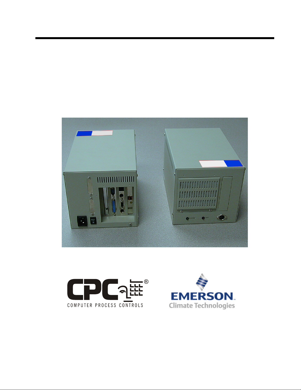
Figure 1-1 - ISIS Front and Rear View
1.1. Overview
The ISIS is an in-store information server that provides a Web-user interface with real-time values to CPC
controllers, as well as other energy management systems.
It collects data from one store’s set of controllers, and can
communicate with a supervisory system, off-loading historical data and alarms. The ISIS also supports LonWorks
and BACnet devices (contact CPC for details).
The ISIS is a compact, embedded processor platform
that uses a hard drive for backup. CPC’s VeriSite supports
access of graphical views of control system data (via TCP/
IP) using a standard Web browser.
1.2. About Windows NT
The base operating system installed on the ISIS is the
®
embedded version of Windows NT
unique in that it does not support a traditional desktop
environment including keyboard and monitor. In addition,
unlike the full version of Windows NT, embedded Windows NT does not directly support user changes to many
Windows settings (except IP address).
. This version is
1.3. Precautions
1.3.1. Safety Precautions
The following items are warnings of a general nature
relating to the installation and start-up of the ISIS controller. Be sure to heed these warnings to prevent personal
injury and/or equipment damage:
• A 120VAC (or 240VAC for international units) circuit powers the ISIS controller. Disconnect power
before installation or servicing to prevent electrical
shock or equipment damage.
• To reduce the risk of electrical shock, this equipment has a grounding-type plug that has a third
(grounding) pin. This plug only fits into a grounding-type outlet. If the plug does not fit into the outlet,
contact a qualified electrician to install the proper
outlet. Do not change the plug in any way.
• Make all connections in accordance with national
and local electrical codes. Use copper conductors
only.
• To reduce the risk of fire or electrical shock, install
in a controlled environment relatively free of contaminants.
1.3.2. Static Discharge Precautions
The following items are cautionary notes that will
help prevent equipment damage and/or loss of data caused
by static discharge:
• Static charges produce voltages high enough to
damage electronic components. The microprocessors and associated circuitry within the ISIS controller series are sensitive to static discharge. Follow
static electricity precautions when installing, servicing, or operating the system.
• Work in a static free area.
• Discharge any static electricity you may have accumulated. Discharge static electricity by touching a
ISIS I&C Manual In-Store Information Server (ISIS) Installation Instructions • 1
Page 8

known, securely grounded object.
• Do not handle the printed circuit board without
proper protection against static discharge. Use a
wrist strap when handling PCBs. The wrist strap
clamp must be secured to earth ground.
1.3.3. General Precautions
Do not remove the ISIS’s metal cover—no user-serviceable parts are inside. Removal of the cover will void
the warranty.
Table 1-1 ISIS Compatibility
Controller Supported Y/N
BCU version 2.20 and
higher
BEC version 4.14 and
higher
Einstein RX version
1.5F01 and higher
Yes
No
Yes
1.4. Included In This Package
Included in this package you should find the following items:
•An ISIS
• A packing slip, which lists the factory settings for IP
address, machine name, and host log on
• ISIS Installation Instructions
• 3-conductor power cord
• Wall-mounting brackets (2)
• Hardware bag including miscellaneous screws, an
extra fan filter, and rubber feet for desktop mount
• Optional items (if ordered):
- NP-UP-OS option: Full Windows NT Workstation software media (diskettes and CD) and license.
- MDM-NP option: Factory-installed modem. Includes a six-foot phone cable. Note that this option also requires the NP-UP-OS (full NT) option.
- NP-485 option: factory-installed dual-port RS485 adapter. Ports are DB-9P (plug) types, which
require customer-supplied cables with DB-9S
(socket) ends to connect to the ISIS.
1.5. Compatibility
ISIS Compatibility with the CPC REFLECS and Ein-
stein product lines:
Einstein BX version
1.5F01 and higher
NOTE: For any ISIS compatibility questions,
contact CPC at 1-800-829-2724.
Yes
1.6. Installation and Start-Up
Read through the entire document before beginning
the installation procedure.
1.6.1. Unpack the ISIS
Unpack the ISIS and inspect the contents of the package for damaged or missing components. If damaged,
notify the appropriate carrier at once and return any damaged components for immediate repair or replacement.
1.6.2. Install the ISIS
Installing the ISIS has four major steps:
1. Physical installation
2. Power Requirements
3. Power up and initial checkout
4. Connect to the ISIS
1.6.2.1. Physical Installation
Table 1-1 ISIS Compatibility
Controller Supported Y/N
REFLECS (Standard) No
RMCC version 2.16
and higher
2 • Included In This Package 026-1306 Rev 0 12-04-02
Yes
Tools Required
The following tools and supplies may be required for
installation:
• Appropriate nut driver or screwdriver (to install the
mounting brackets, if used)
• Small flat-blade screwdriver (for LON connector)
Page 9

Location for Mounting
• This product is intended for indoor use only. The
unit should not be exposed to ambient conditions
outside of the range of 0ºC (32 degrees F) to 35ºC
(95 degrees F) and relative humidity outside the
range 5% to 95% non-condensing.
NOTES:
•A clean environment with ongoing minimum exposure to dust is strongly recommended.
• During the construction phase, make sure to
keep construction and metallic particles away
from the ISIS. If necessary, keep the ISIS powered off and covered. For additional information, see Section 1.16.1., Filter Maintenance.
of the cabinet and the connectors will be situated towards the top of the cabinet.
1.8. Power Requirements
The power connector of the ISIS must be connected to
a dedicated 120VAC, 60Hz circuit capable of providing at
least 1.5 Amperes, plus sufficient capacity for test equipment.
International units must be wired to a 240VAC, 50Hz
source of power capable of providing at least 0.75
Amperes, plus sufficient capacity for test equipment.
Domestic ISIS units are shipped with a cord-set that
consists of a NEMA-5 15P plug and an IEC 320 connector. If, for some reason, the ISIS is to be directly connected
to a power source, use one of the color schemes shown in
Table 1-2 on page 3.
1.7. Mounting
There are two mounting options for the ISIS: Desktop
and Cabinet.
Desktop
Four non-skid rubber feet are provided for desktop
mounting. Do not use the mounting brackets if you intend
to mount the unit on your desktop. The rubber feet are
self-adhesive. Simply remove them from the paper backing and place them at each outside corner edge of the bottom of the unit.
Cabinet
Mount the ISIS in a cabinet, install the mounting
brackets on either side of the unit with the sheet metal
screws provided in the hardware bag. The mounting
brackets are interchangeable.
Observe the following when mounting the ISIS in a
cabinet:
• Maintain three inches of clearance on the sides, top,
and bottom of the unit to provide adequate ventilation.
• Mount the unit in such a manner as to provide maximum efficiency in cooling. The intake for the fan is
located at the front of the unit just above the POWER and HDD LEDs. Air exits the unit through grillwork located to the left and the rear of the unit.
• Mount the unit in such a way as to orient the intake
towards the bottom of the cabinet and have airflow
up through the unit and exit to the left and top of the
cabinet.
• With the ISIS properly oriented in its cabinet, the intake for the fan will be situated towards the bottom
Table 1-2 Power Wiring Color Schemes
North America International
BLACK: Line BROWN: Line
WHITE: Neutral BLUE: Neutral
GREEN: Ground GREEN/YELLOW:
Ground
1.9. Connections
Make connections to the ISIS in the following order. For specific details on communications wiring, refer to Section 1.11., Wiring Details.
1. Connect the Ethernet cable. The ISIS provides a single auto-sensing 10BASE-T or
100BASE-TX (RJ-45) connector on slot 1.
Make this connection to your LAN (local
area network).
2. If applicable, make the RS-232 connection.
Plug the DB-9 RS-232 cable into COM1, or
COM2 if COM1 is occupied.
3. Connect the LonWorks network connection.
The ISIS provides a single, two-pin 78Kbaud free topology connection on slot-4.
Make this connection to your Echelon FTT10 LonWorks trunk.
4. Connect the power cable. Using the 3-conductor power cord supplied with the ISIS,
connect the PC plug to the keyed connector
ISIS I&C Manual In-Store Information Server (ISIS) Installation Instructions • 3
Page 10

on the back of the ISIS and the standard AC
power connector to a dedicated 120VAC or
(240VAC) duplex outlet. See Section 1.8.,
Power Requirements. Other connections are
not needed at this time. The DIN connector
on the front of the unit (if supplied) is a 84key keyboard port that is not used. The connector above the power switch provides a
parallel communications connection. The
RS-232 serial ports (COM1 and COM2) and
any RS-485 ports (if the ISIS was ordered
with an NP-485 option) are used to support
serially connected integrations.
1.10. Power Up and Initial Checkout
Once you have installed the ISIS, power ON the unit,
allow Windows NT to load, and verify that you can access
the device over the network.
NOTES:
•Windows NT takes approximately 1-1/2 minutes to load on the ISIS.
• Once the operating system has been successfully
loaded, you can access the ISIS over the network
using the Niagara host administration tool (Admin Tool). This is the recommended method to
access an ISIS.
• An ISIS can also be accessed over a LAN using
a networked PC and Windows NT Explorer.
1.11.1.Ethernet
Connection is made via a standard male RJ-45 (8wire) connector. Using a Category 5 unshielded twisted
pair (UTP) cable, connect one end of the cable to the RJ45 connector on the ISIS (slot 1), and the other end to a
hub on the Ethernet LAN. The maximum end-to-end distance from the controller to the hub is 328 feet (100m).
This connection is capable of running at either 10
Mbps or 100 Mbps—it automatically adjusts to either
speed. This means the ISIS can exist on the same network
with a mixture of 10BaseT and 100BaseTX hardware connected to a smart 10/100 hub capable of adjusting to the
devices it supports.
1.11.2.Serial
There are two RS-232 serial ports on the ISIS, labeled
COM1 and COM2. These are DTE-type ports, using
industry-standard DB-9 male connectors. Typically, a
standard “null-modem” cable is used to communicate to
another DTE device. A “straight-through” cable is used to
communicate to a DCE device, such as a modem.
1.11.3.Modem (Optional)
An ISIS ordered with the MDM-NP option has a factory-installed modem, typically located in slot 3. Connect
one end of a standard flat satin telephone cable (4-connector) to the modem’s top RJ-11 connector (LINE), and the
other end to an analog telephone port.
In the ISIS, this modem uses COM3 (unless an RS485 Option is installed, in which case it is COM5).
1.11. Wiring Details
The following section provides details on communications wiring. All wiring is made to ports on the rear of
the ISIS. (See Figure 1-2).
• Ethernet
•Serial
• Modem (Optional)
NOTE: For power wiring details, refer to
Section 1.8., Power Requirements. Wiring
details for the RS-485 option are in Section
1.13., RS-485 Option.
4 • Power Up and Initial Checkout 026-1306 Rev 0 12-04-02
Page 11

1.12. Figures
1.12.1.ISIS Connector Layout
6-3/4 in
172 mm
Power Connector
7-7/8 in
200 mm
COM1
COM2
I
O
Power Switch
Ethernet
(RJ-45)
1234
VIDEO
PRINTER
MOUSE
Ethernet 10BaseT
KEYBOARD
(optional)
Modem
Line RJ-11
RS-232 COM1
RS-232 COM2
Printer LPT1
LINE
PHONE
COM3
LON
FTT-10
6-9/16 in
167 mm
LON Trunk (FTT-10)
POWER LED
HDD LED
6-13/16 in
173 mm
COM1
ISIS ordered with
NP-485 option
Power Connector
COM2
Power Switch
1234
VIDEO
PRINTER
I
O
MOUSE
Ethernet 10BaseT
KEYBOARD
Figure 1-2 - ISIS Dimensions and Connector Layout Details
NOTE: Ports may vary depending on ISIS
model.
LINE
PHONE
RS-485 port, COM3
COM3
LON Trunk (FTT-10)
RS-485 port, COM4
RS-485 option (model NP-485) has two DB-9P
(male) connectors and is typically located in slot 2.
See Section 1.13., RS-485 Option, for details on
port pinouts and cable diagrams.
ISIS I&C Manual In-Store Information Server (ISIS) Installation Instructions • 5
Page 12

1.12.2.Mounting Detail
Figure 1-3 - ISIS (top view) RS-485 Option
1.13. RS-485 Option
An ISIS ordered with the NP-485 option has a factory-installed RS-485 adapter, located in slot 2 (Figure 1-
2). This is a dual-port adapter with two standard male DB9 plug (male) connectors.
6 • RS-485 Option 026-1306 Rev 0 12-04-02
Table 1-3 - COM Port Assignments for RS-485 Ports on an ISIS
RS-485 Option
RS-485 Adapter COM Port Assignments
Top DB-9 Connector COM3
Bottom DB-9 Connector
COM4
Page 13

.
1.14. Wiring Details
Each connector supports both full and half-duplex for
RS-485 signals on the DB-9 connectors are given in this
table:
Table 1-4 - Pinouts for RS-485 ports on an ISIS RS-485 option (model NP-485).
NP-485 option DB-9 Connector, RS-485 Pinouts
DP-9P (male) connector Pin Name Description
1 RD (A) Receive Data A
1
6
5
9
1.15. Cable Diagrams
You will need to make cables to connect the DB-9P
connectors on the ISIS’s RS-485 adapter to the RS-485
device bus. Use the following cable diagrams and the
appropriate DB-9S (socket) connectors for attachment to
the ISIS ports.
2 TD (B) Transmit Data B
3 TD (A) Transmit Data A
5 GND Signal Ground
9 RD (B) Receive Data B
1.15.2.RS-485 Half Duplex
An RS-485 bus wired for half-duplex is commonly
known as a “two-wire” bus. Cabling between devices uses
three (3) conductors: a single twisted-pair plus a shield
(ground) wire.
Use the following cable pinouts to make a cable to
connect the ISIS using RS-485 half-duplex:
1.15.1.RS-485 Full Duplex
An RS-485 bus wired for full-duplex is commonly
known as a “four-wire” bus. Cabling between devices uses
five conductors: two twisted-pairs plus a shield (ground)
wire.
Use the following cable pinouts to make a cable to
connect the ISIS using RS-485 full-duplex:
ISIS DB-9
TD (A–) Pin 3
TD (B+ ) Pin 2
RD (A–) Pin 1
RD (B+ ) Pin 9
GND Pin 5
Figure 1-4 - RS-485 Full Duplex Cable Diagram
RS-485 Bus
RD (–)
RD (+)
TD (–)
TD (+)
GND
ISIS DB-9
TD (A–) Pin 3
TD (B+) Pin 2
RD (A–) Pin 1
RD (B+) Pin 9
GND Pin 5
Note:
Jumper Pins: 1 & 3
2 & 9
Figure 1-5 - RS-485 Half Duplex Cable Diagram
RS-485 Bus
(–)
(+)
GND
ISIS I&C Manual In-Store Information Server (ISIS) Installation Instructions • 7
Page 14

1.16. Maintenance
1.17. Replacement Parts
Use the following procedures to perform simple
maintenance tasks on the ISIS controller.
1.16.1.Filter Maintenance
Following the construction phase, and then on a quar-
terly (minimum) basis, the air filter on the fan intake
should be either:
• Replaced, or
• Cleaned
To clean or replace the air filter, remove the two
screws that secure the intake grill. Lift the grill away from
the unit and remove the filter. Clean the filter by washing
it with warm, soapy water and thoroughly rinsing and drying it before replacing. Replace the filter, then fasten the
intake grill securely.
Regular filter maintenance promotes cooler internal
temperature and longer equipment life. If the ISIS has Niagara Release 2.2 or higher, its main board temperature
under the CPU (and other internal variables) can be moni-
tored by the station running on it.
Servicing the ISIS may call for replacement parts.
There are three categories of parts:
• Non-replaceable
• Standard Replacement
• Field Replacement
NOTE: For all replacement part numbers,
contact CPC at 1-800-829-2724.
1.18. Non-Replaceable Parts
Other than the parts listed in the replacement parts
section, there are no serviceable components on an ISIS.
1.18.1.Memory
Any addition, modification, or replacement of mem-
ory components requires software configuration and is not
a field upgrade.
NOTE: Alternately, after the construction
phase is complete, you can remove the ISIS
air filter. This is recommended only for
installations with a high exposure to heat
(average temperature close to 95ºF (35ºC), and where
the ISIS environment remains continuously clean.
1.16.2.Real-Time Clock Battery
The Central Processor Card of the ISIS is equipped
with a 3.0VDC Lithium battery. The battery provides
back-up power to the Real-Time Clock and the CMOS
data area that stores the BIOS setup information. The
design life of the battery is 10 years. Replacement of the
battery requires removal of the Central Processor Card and
re-entry of the setup information.
NOTE: Consult with CPC before changing
the battery in the ISIS.
NOTE: For additional information on modifying the memory capacity of the ISIS, consult CPC for technical support at 1-800-829-
2724.
1.18.2.Fuses
An internal 5 x 20 mm, Slo-Blo fuse rated at 1.25A,
250VAC (domestic) or 0.75A, 250VAC (international) is
used for power circuit protection. This circuitry is not
user-serviceable. If the power circuitry is suspect, contact
the factory for replacement (field replacement will void
the ISIS warranty).
8 • Maintenance 026-1306 Rev 0 12-04-02
Page 15

1.19. Standard Replacement Parts
Standard replacement parts are listed in Table 1-5 on
page 9 and can be ordered from stock without restriction.
Standard replacement parts cannot be returned for credit
and should be disposed of in an appropriate manner
Table 1-5 Standard Replacement Parts
Description Quantity
Mounting Brackets Pair
Fan Filter 1
NOTE: For field replacement units and standard replacement part numbers, contact CPC
at 1-800-829-2724.
If you suspect this product is causing interference,
turn your computer on and off while the radio or TV is
showing interference. If the interference disappears when
you turn the computer off and reappears when you turn the
computer on, something in the computer is causing the
interference.
To reduce interference, try these suggestions:
• Change the direction of the radio or TV antenna.
• Move the computer, radio, or TV. For example, if
the computer is to the right of the TV, move it to the
left of the TV, or move them farther apart.
• Plug the computer into a different electrical outlet
than the radio or TV.
• Ensure that all expansion slots (on the back or side
of the computer) are covered. Also, ensure that all
metal retaining brackets are tightly attached to the
computer.
1.20.2.Canadian Department of Communications
This digital apparatus does not exceed the Class B
limits for radio noise emissions from a digital apparatus as
set forth in the radio interference regulations of the Canadian Department of Communication.
1.20. Certifications
1.20.1.Federal Communications Commission
The device complies with Part 15 of the FCC Rules.
Operation is subject to the following two conditions: 1)
this device may not cause harmful interference, and 2) this
device must accept any interference received including
interference that may cause undesired operation.
The equipment has been tested and found to comply
with the limits for a Class B digital device, pursuant to
Part 15 of the FCC Rules. These limits are designed to
provide reasonable protection against harmful interference
when the equipment is operated in a commercial environment. This equipment generates, uses, and can radiate
radio frequency energy and, if not installed and used in
accordance with the instruction manual, may cause interference, in which case, the user will be required to correct
the interference at his own expense.
This product generates and uses energy of about the
same frequency as radio and TV broadcasts. Installed correctly, it may interfere with reception of radio and TV
broadcasts.
ISIS I&C Manual In-Store Information Server (ISIS) Installation Instructions • 9
Page 16

1.20.3.Einstein Connection
Figure 1-6 - ISIS to Einstein
Refer to Figure 1-2 for a closer look at connectors
and LEDs for the ISIS. To connect an Einstein controller
to the ISIS, use an Ethernet connection:
5. Plug one end of the Category 5 unshielded
twisted pair (UTP) Ethernet cable into the RJ45 connector on the ISIS.
6. Plug the other end of the Ethernet cable into
an empty port on a LAN hub or switch. The
maximum end-to-end distance from the controller to the hub is 328 feet (100m).
7. Plug one end of another Ethernet cable into
the RJ-45 Ethernet port on the Einstein that
has the PC-104 network card installed.
8. Plug the other end of the Ethernet cable into
an empty port on a LAN hub or switch.
9. All additional Einstein units should be connected to the networked Einstein via the Echelon network. (For more information about
the Echelon network, see the CPC Einstein
RX Refrigeration Controller User’s Guide)
NOTE: The Ethernet connection must be
made prior to applying power to the controller.
10 • Certifications 026-1306 Rev 0 12-04-02
Page 17

1.20.4.REFLECS Connection
Figure 1-7 - ISIS to REFLECS
Refer to Figure 1-2 for a closer look at connectors and LEDs for the ISIS. To connect a REFLECS controller to the ISIS, follow these steps:
1. Take the supplied CPC-approved network cable and plug the 9-pin connector into RS-232
COM 1.
2. Plug the 4-pin connector into the COM C port
on the REFLECS. (For more information, see
the CPC Refrigeration Monitor and Case
Control Installation and Operation Manual)
NOTE: The Ethernet connection must be
made prior to applying power to the controller.
ISIS I&C Manual In-Store Information Server (ISIS) Installation Instructions • 11
Page 18

 Loading...