

Page 1
AE4-1322
™
Copeland ScrewCopeland Screw
Copeland Screw
Copeland ScrewCopeland Screw
™
CompressorsCompressors
Compressors
CompressorsCompressors
April 2002
Semi-Hermetic Compact Semi-Hermetic Compact
Semi-Hermetic Compact
Semi-Hermetic Compact Semi-Hermetic Compact
SCH2 & SCA2SCH2 & SCA2
SCH2 & SCA2
SCH2 & SCA2SCH2 & SCA2
High Temp Compressors
35 – 140 Horsepower
1 General1 General
1 General
1 General1 General
2 Design and functions2 Design and functions
2 Design and functions
2 Design and functions2 Design and functions
2.1 Design features
2.2 Compression process Vi control
2.3 Capacity control and start unloading
2.4 Hydraulic control
2.5 Starting the compressor
2.6 Infinite capacity control
Oil circulation
Contents
5 Economizer operation5 Economizer operation
5 Economizer operation
5 Economizer operation5 Economizer operation
Application ManualApplication Manual
Application Manual
Application ManualApplication Manual
5.1 General
5.2 Operation principal
5.3 ECO operation with subcooling circuit
5.4 ECO operation with intermediate
pressure receiver
5.5 Layout and selection
recommendations
5.6 Additional components
5.7 Control
3 Lubricants3 Lubricants
3 Lubricants
3 Lubricants3 Lubricants
4 Integration into the refrigeration circuit4 Integration into the refrigeration circuit
4 Integration into the refrigeration circuit
4 Integration into the refrigeration circuit4 Integration into the refrigeration circuit
1.1 Mounting the compressor
1.2 System layout
1.3 Guide lines for special system
variations
1.4 Additional cooling by liquid injection
1.5 Additional cooling by external oil
cooler
© 2002 Copeland Corporation
Issued 4-2002
Printed in U.S.A.
6 Electrical connections6 Electrical connections
6 Electrical connections
6 Electrical connections6 Electrical connections
6.1 Motor design
6.2 Selection of electrical components
6.3 Compressor protection system
6.4 Schematic wiring diagrams
Page 2
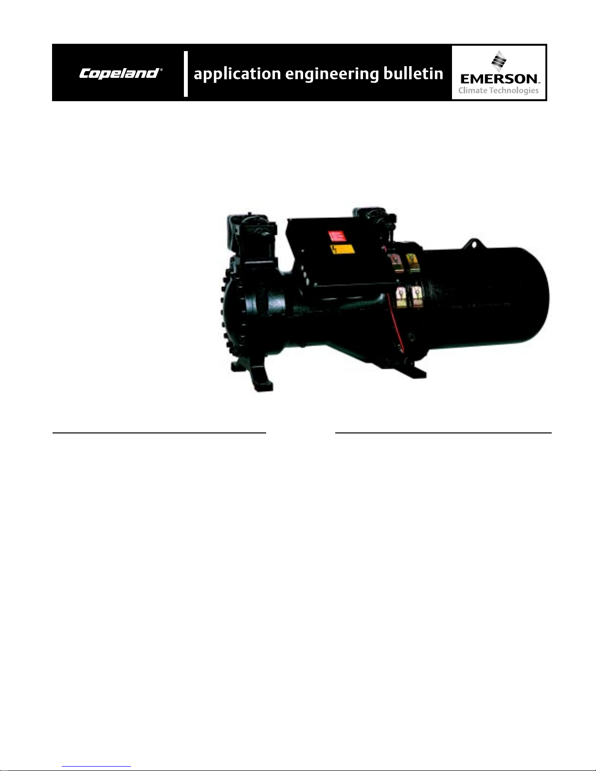
Semi-hermetic compact screwsSemi-hermetic compact screws
Semi-hermetic compact screws
Semi-hermetic compact screwsSemi-hermetic compact screws
SCH2/SCA2 seriesSCH2/SCA2 series
SCH2/SCA2 series
SCH2/SCA2 seriesSCH2/SCA2 series
35 to 140 HP Nominal motor power35 to 140 HP Nominal motor power
35 to 140 HP Nominal motor power
35 to 140 HP Nominal motor power35 to 140 HP Nominal motor power
11
GeneralGeneral
1.
General
11
GeneralGeneral
This new series represents the result of further development to provide a simplified and favorably priced screw
compressor for use in factory made systems.
Contrary to the semi-hermetic and open type, SHM/
SHL and SDM/SDL compressor models for commercial
and industrial installation, the compact screws are
designed with an integral oil separator. The effort
involved in installation is therefore comparable with that
for semi-hermetic reciprocating compressors.
In addition to this, the electrical control and the monitoring of the oil circuit has been simplified. The proven
basic construction and the ease of service have been
retained.
The most modern screw compressor technology is now
available in the middle capacity range for compact liquid
chillers and air conditioning equipment.
2. Design and function2. Design and function
2. Design and function
2. Design and function2. Design and function
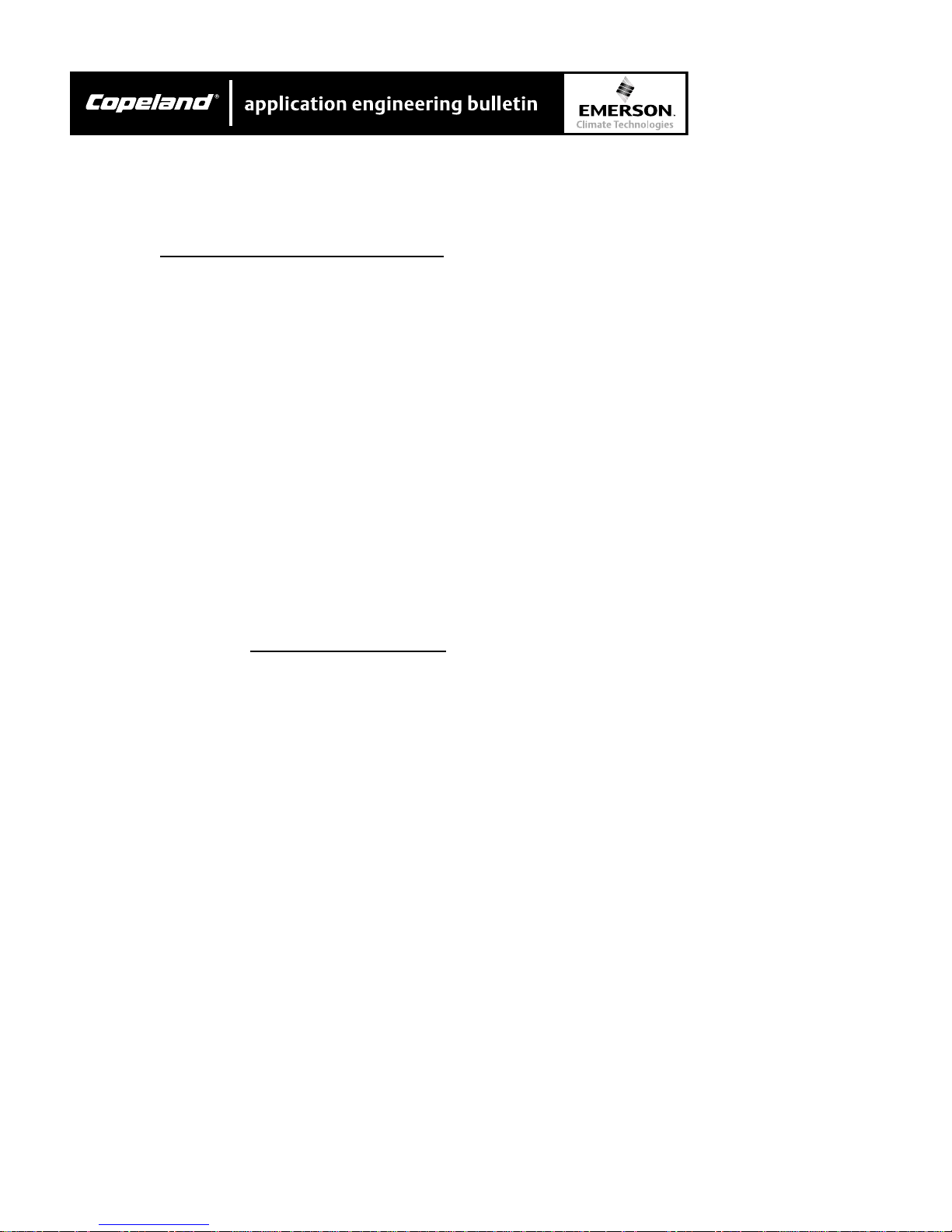
2.1 Design features
Copeland Compact screws are of the twin rotor design
with a newly-developed profile geometry (lobe ratio 5:6).
The main parts of these compressors are the two rotors
(male and female rotor), which are fitted into a closed
housing. The rotors are precisely located at both ends
in rolling contact bearings (radial and axial), which, in
conjunction with the generously sized oil supply
chambers, provides optimum emergency running
characteristics.
Owing to the specific design, this type of compressor
does not require any working valves. To protect against
reverse running when the compressor is switched off
(expansion operation) a check valve is incorporated in
the discharge chamber (this valve does not, however,
replace any check valves required by the system
design). An internal pressure relief valve is utilized for
over-pressure protection.
The compressor is driven by a three-phase asynchronous motor, which is built into the compressor housing.
The motor rotor is located on the shaft of the male
screw rotor. Cooling is achieved by cold refrigerant
AE4-1322
vapor, which mainly flows through bores in the motor
rotor.
The main technical features:
Balanced product rangeBalanced product range
Balanced product range
Balanced product rangeBalanced product range
• •
• 8 basic models
• •
• •
• Tight performance graduation
• •
Minimal space requirements and convenientMinimal space requirements and convenient
Minimal space requirements and convenient
Minimal space requirements and convenientMinimal space requirements and convenient
piping designpiping design
piping design
piping designpiping design
• Shortest installed length in its performance category
- shut-off valves / connections within compressor
dimensions
• Suction and discharge gas connections can be
rotated in 90° increments
• Terminal box accessible from top, wire access from
underneath
Universal applicationsUniversal applications
Universal applications
Universal applicationsUniversal applications
••
• R134a, R407C and R22
••
••
• R404A, R507A upon request
••
••
• With or without economizer
••
••
• Optimized R-134a version (SCA2)
••
New high-efficiency profileNew high-efficiency profile
New high-efficiency profile
New high-efficiency profileNew high-efficiency profile
• Further developed geometry
• High rigidity
• Patented manufacturing process for highest
precision
• High tip speed to minimize blow-by
Double-walled, pressure-compensated rotorDouble-walled, pressure-compensated rotor
Double-walled, pressure-compensated rotor
Double-walled, pressure-compensated rotorDouble-walled, pressure-compensated rotor
housinghousing
housing
housinghousing
••
• Extremely stable, therefore no expansion even at
••
high pressure levels
••
• Additional sound attenuation
••
Proven, long-life bearings with pressure unloadingProven, long-life bearings with pressure unloading
Proven, long-life bearings with pressure unloading
Proven, long-life bearings with pressure unloadingProven, long-life bearings with pressure unloading
• Robust axial bearings in tandem configuration
• Bearing chamber pressure isolated by seal rings
• Pressure unloading of axial bearings
Optimized oil managementOptimized oil management
Optimized oil management
Optimized oil managementOptimized oil management
• Three-stage oil separator
• Long-life oil filter 10 µ mesh size
• Pressure relieved bearing chamber ensuring minimum refrigerant dilution in the oil and thus higher
viscosity
Large volume motor for part winding or direct startLarge volume motor for part winding or direct start
Large volume motor for part winding or direct start
Large volume motor for part winding or direct startLarge volume motor for part winding or direct start
- optional star delta design- optional star delta design
- optional star delta design
- optional star delta design- optional star delta design
• Especially high efficiency
© 2002 Copeland Corporation
Issued 4-2002
Printed in U.S.A.
2
Page 3
• Integrated PTC sensors in each winding coil
• Slot keys for maximum operating safety
• Stator is slide fit (field replaceable)
Intelligent electronicsIntelligent electronics
Intelligent electronics
Intelligent electronicsIntelligent electronics
• Thermal motor temperature control by winding PTCs
• Phase sequence control for direction of rotation
• Manual reset lock-out
• Oil temperature protection by PTC sensor
Flexible with additional coolingFlexible with additional cooling
Flexible with additional cooling
Flexible with additional coolingFlexible with additional cooling
• Direct liquid injection
• External oil cooler for extended application and
highest efficiency
Dual capacity controlDual capacity control
Dual capacity control
Dual capacity controlDual capacity control
• Infinite or 4-step slide control with V
compensation.
i
Alternative operation modes by varying the control
sequence only - no need for compressor modification
• Simple control by solenoid coils
• Automatic start unloading
Economizer with sliding suction positionEconomizer with sliding suction position
Economizer with sliding suction position
Economizer with sliding suction positionEconomizer with sliding suction position
• Unique for compact screws
• Efficient economizer operation with part load as well
• Highest cooling capacity and energy efficiency at full
and part load conditions
Fully equippedFully equipped
Fully equipped
Fully equippedFully equipped
• Capacity control / start unloading
• Suction and Discharge shut-off valve
• Check valve in discharge gas outlet
• Oil sight glass
• Insertion type oil heater with sleeve
• Oil fill / drain service valve
• Suction gas filter with large surface are and fine mesh
• Electronic protection system
Proven optional accessoriesProven optional accessories
Proven optional accessories
Proven optional accessoriesProven optional accessories
• Oil level switch
• Shut-off valve / adapter for economizer operation and
liquid injection
• Adapter for external oil cooler
2.2 Compression process V2.2 Compression process V
2.2 Compression process V
2.2 Compression process V2.2 Compression process V
-control-control
-control
-control-control
ii
i
ii
With screw compressors, suction, compression and
discharge occur in one flow direction. With this process
the suction gas is pressed into the profile hollows by the
profile peaks. The volume is steadily reduced and it is
thereby compressed. The compressed gas is then
discharged through a discharge port whose size and
geometry determine the so called “internal volume ratio
AE4-1322
(Vi)”. This value must have a defined relationship to the
mass flow and the working pressure ratio, to avoid
losses in efficiency due to over- and under-compression.
The internal discharge ports of the SCH2/SCA2 screw
compressors are designed for a very wide application
range.
In view of high efficiency and operational safety a part of
the discharge channel is integrated into the control
slide, which enables a Vi control at part load conditions.
Due to this the internal volume ratio (Vi) virtually remains constant down to approximately 70% part load.
The economizer channel built into the control slide is
another outstanding feature (figure 3). It enables a fully
functional operation of the subcooler circuit independently from the compressor’s load conditions. This is a
design solution which is unique for screw compressors
of this size. This ensures highest possible capacity and
efficiency at both full and part load conditions. For
details regarding economizer operation see Section 5.
2.3 Capacity control and start unloading2.3 Capacity control and start unloading
2.3 Capacity control and start unloading
2.3 Capacity control and start unloading2.3 Capacity control and start unloading
SCH2/SCA2 models are provided as a standard with a
“Dual Capacity Control” (slide system). This allows for
infinite infinite
infinite or
infinite infinite
4-step capacity control4-step capacity control
4-step capacity control without compressor
4-step capacity control4-step capacity control
modifications. The different operating modes can be
achieved by changing the control sequences of the
solenoid valves.
The special geometry of the slide means that the
volume ratio Vi is adjusted to the operating conditions in
part-load operation. This provides particularly high
efficiency.
© 2002 Copeland Corporation
Issued 4-2002
Printed in U.S.A.
3
Page 4
AE4-1322
Oil Hydraulic Scheme
Another feature of this system is the automatic startunloading. It reduces starting torque and acceleration
times considerably. This not only puts lower stresses
on motor and mechanical parts but also reduces the
load on the power supply network.
Significant design features are the robust dimensioning
as well as the precise guidance of the slide elements
and the control piston. Capacity control is achieved by
means of solenoid valves that are flanged on to the
compressor. A “dual set point controller” or any similar
component is suitable as a control module.
2.4 Hydraulic control2.4 Hydraulic control
2.4 Hydraulic control
2.4 Hydraulic control2.4 Hydraulic control
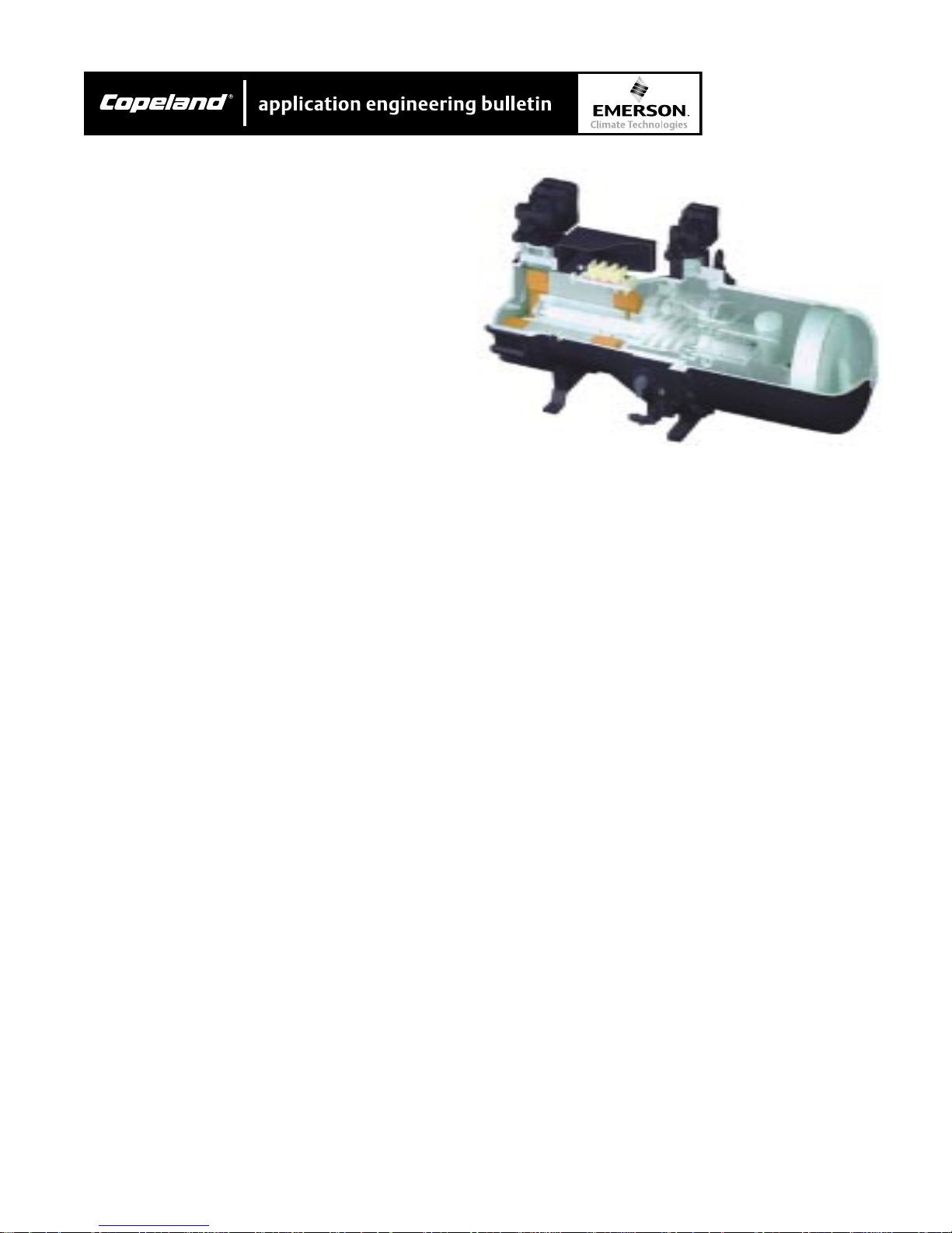
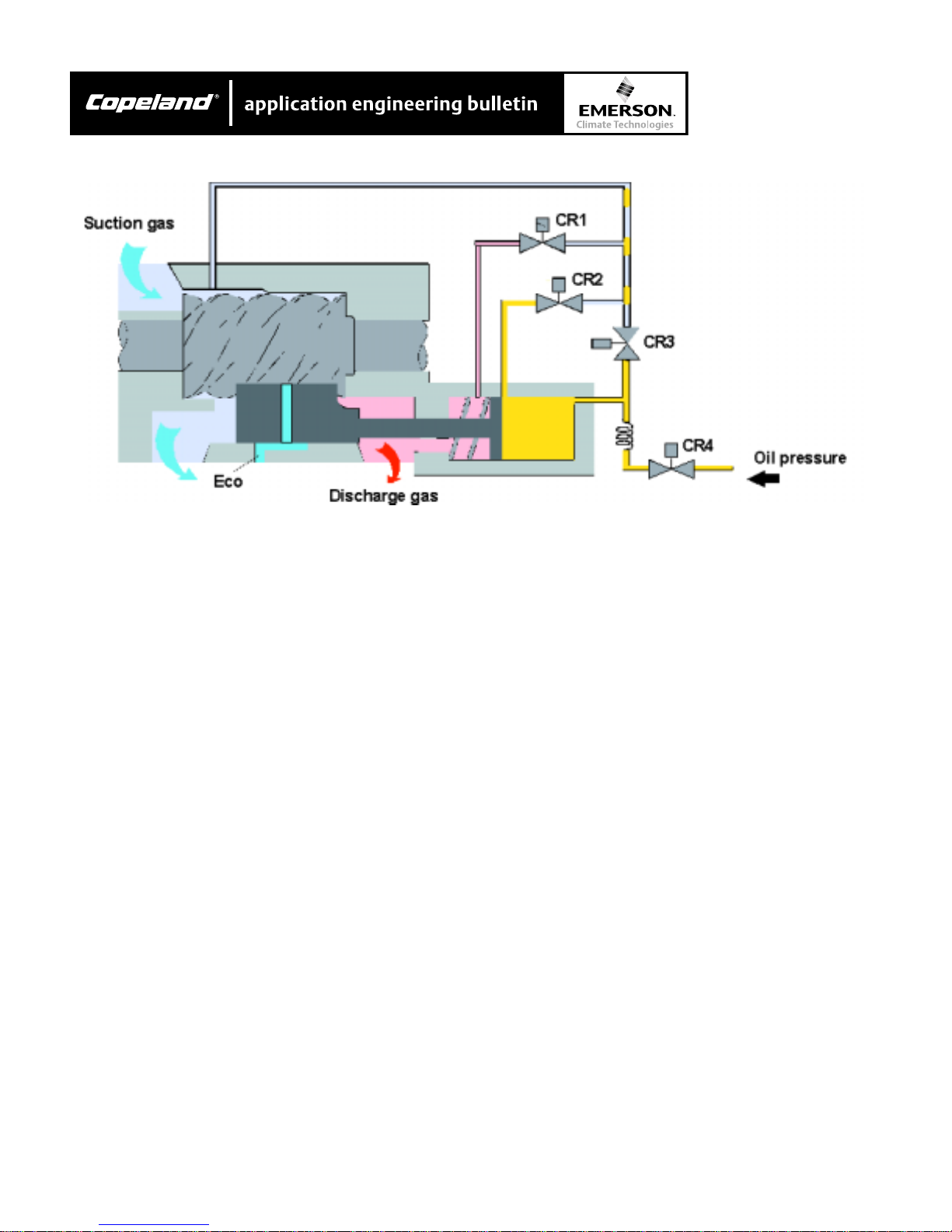
Figure 3 shows the design principle of the hydraulic
scheme. By moving the slide the suction gas flow is
controlled.
If the slide is moved totally to the suction slide (in the
figure 3 to the left), the working space between the
profiles is filled with suction gas. The more the slide is
moved to the discharge slide, the smaller the resulting
profile volume becomes. Less refrigerant is taken in.
The mass flow is lower, and the cooling capacity
decreases.
Figure 3
chamber increases. The slide is moved to the suction
side. The cooling capacity increases.
If the valve CR1, CR2 or CR3 is opened, the pressure
on the hydraulic piston decreases. By means of the
discharge gas the slide is pressed to the discharge
side. The cooling capacity is reduced.
2.5 Starting the compressor2.5 Starting the compressor
2.5 Starting the compressor
2.5 Starting the compressor2.5 Starting the compressor
During the shut - down of the compressor the solenoid
valve CR3 is open. The pressure in the hydraulic
cylinder is then released. The spring (fig. 3) pushes the
slide to the discharge side end position.
When starting the compressor, it is unloaded. Valve
CR4 is energized on demand thus moving the slide
towards the suction side. The refrigerating capacity
increases to the set load condition by energizing the
valves CR1, CR2 or CR3.
2.6 Infinite capacity control2.6 Infinite capacity control
2.6 Infinite capacity control
2.6 Infinite capacity control2.6 Infinite capacity control
Infinite capacity control is recommended for systems
where high control accuracy is required. For control
principle see charts A, B, and C.
The slide is controlled by a hydraulic piston. If the valve
CR4 is opened, the oil pressure in the pressure
© 2002 Copeland Corporation
Issued 4-2002
Printed in U.S.A.
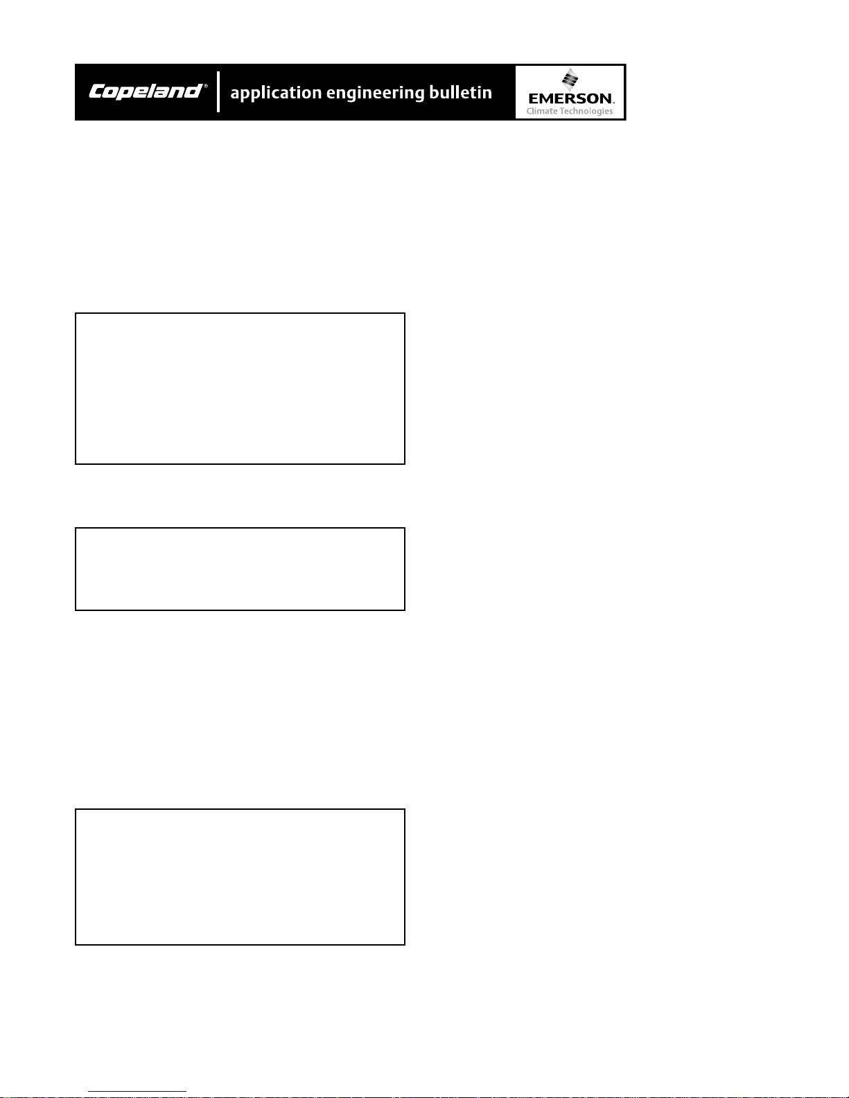
If the actual value is within the set control range H, the
cooling demand of the plant remains unchanged. Then
4
Page 5
AE4-1322
there is no need to move the slide. No solenoid valve
is energized.
The control input can be the air or water temperature at
the evaporator or the suction pressure.
Chart A
Control Sequence – Infinite Capacity ControlControl Sequence – Infinite Capacity Control
Control Sequence – Infinite Capacity Control
Control Sequence – Infinite Capacity ControlControl Sequence – Infinite Capacity Control
Minimum CapacityMinimum Capacity
Minimum Capacity
Minimum CapacityMinimum Capacity
mm
m
mm
CR 1 2 3 4
Start/Stop mmlm
⇑⇑
Cap
⇑ mmml
⇑⇑
⇓⇓
Cap
⇓ mmlm
⇓⇓
⇔⇔
Cap
⇔ mmmm
⇔⇔
Cap. 100% mmml
Cap. Min.W mmlm
Chart B
Control Sequence – Infinite Capacity ControlControl Sequence – Infinite Capacity Control
Control Sequence – Infinite Capacity Control
Control Sequence – Infinite Capacity ControlControl Sequence – Infinite Capacity Control
Minimum Capacity 50%Minimum Capacity 50%
Minimum Capacity 50%
Minimum Capacity 50%Minimum Capacity 50%
Cap
4 Cap.
⇑⇑
⇑
⇑⇑
mm
m
mm
mm
m
mm
mm
m
mm
ll
l
ll
ll
l
ll
mm
m
mm
mm
m
mm
Min.50%
Increased cooling demandIncreased cooling demand
Increased cooling demand
Increased cooling demandIncreased cooling demand
If the actual value exceeds the upper set point, the
cooling demand has increased (operating point A in fig.
4). The solenoid valve CR4 is opened for short intervals
till the actual value is within the set control range again
(operating point B). Now the compressor operates with
increased cooling capacity.
Chart C
Control Sequence – 4-Step Capacity ControlControl Sequence – 4-Step Capacity Control
Control Sequence – 4-Step Capacity Control
Control Sequence – 4-Step Capacity ControlControl Sequence – 4-Step Capacity Control
Decreased cooling demandDecreased cooling demand
Decreased cooling demand
Decreased cooling demandDecreased cooling demand
A decreased cooling demand falls below the lower set
point (operating point C). The solenoid valve CR3 now
opens for short intervals till the actual value is within
the set control range again (operating point D). The
compressor operates with decreased cooling capacity.
With the solenoid valves CR3 / CR4, capacity can be
controlled between 100% and nominally 25%. Alternatively valves CR2 / CR4 can be energized; in this case
control will be limited between 100% and nominally
50%.
The limitation to a minimum of approximately 50%
cooling capacity is recommended for the following
application conditions (control with valves CR2 / CR4):
• In case of operation at high-compression ratios /
condensing temperatures, the main concern is high
discharge temperature.
• For systems with multiple compressors either used
in split or singlecircuits. Under these conditions
capacity control between 100 and 50%, in combination with individual compressor on/off cycling,
guarantees highest possible efficiency – without
significant restrictions in the application range. Due
to the usually lowered condensing temperature at
part load conditions, the lead compressor can even
be operated very effectively down to nominal 25% of
cooling capacity (with valves CR3 / CR4)
2.7 4-step capacity control2.7 4-step capacity control
2.7 4-step capacity control
2.7 4-step capacity control2.7 4-step capacity control
This type of capacity control is particularly suited to
systems with high inertia – in connection with indirect
cooling, for example. Liquid chillers are typical applications. Chart C shows the control of the solenoid valves
or the individual capacity steps.
CR 1 2 3 4
Start/Stop mmlm
Cap 25% mmly
Cap 50% mlmy
Cap 75% lmmy
Cap. 100% mmmm
Solenoid Coil De-Energized Solenoid Coil De-Energized
m
Solenoid Coil De-Energized
Solenoid Coil De-Energized Solenoid Coil De-Energized
Solenoid Coil EnergizedSolenoid Coil Energized
l
Solenoid Coil Energized
Solenoid Coil EnergizedSolenoid Coil Energized
Solenoid Coil Pulsing (10 secs. on / 10 secs. off) Solenoid Coil Pulsing (10 secs. on / 10 secs. off)
y
Solenoid Coil Pulsing (10 secs. on / 10 secs. off)
Solenoid Coil Pulsing (10 secs. on / 10 secs. off) Solenoid Coil Pulsing (10 secs. on / 10 secs. off)
© 2002 Copeland Corporation
Issued 4-2002
Printed in U.S.A.
The cycle time of the intermitting valve, CR4, should be
adjusted to about 10 seconds before commissioning.
Even shorter intervals may be necessary, particularly
with systems with high pressure differences. Therefore,
in this case adjustable time relays should be used.
For this type of operation a restriction of minimum
refrigeration capacity to approximately 50% is also
recommended, as with the systems described in
Section 2.6. Control is then effected with the CR4 valve
(intermittent) and with CR1 (75%) and CR2 (50%).
5
Page 6
AE4-1322
2.8 Oil circulation2.8 Oil circulation
2.8 Oil circulation
2.8 Oil circulation2.8 Oil circulation
The lubrication circuit is designed as is typical for
screw compressors. This type of design, however, has
a vessel directly flanged-on to the compressor housing
at the high-pressure side. It contains the oil reservoir.
The vessel simultaneously serves as an oil separator.
The oil circulation results from the pressure difference
to the oil injection point, where the pressure level is
slightly above suction pressure. The oil flows through a
generously sized filter element to the throttle point and
subsequently to the bearing chambers and the profile
spaces of the rotors. The oil is then transported
together with the refrigerant vapor in the direction of
compression. In addition to lubrication it also provides
a dynamic seal between the rotors and between the
housing and the rotors. The oil then flows together with
the compressed vapor into the reservoir vessel. Here oil
and vapor are separated in a highly efficient process.
The oil collects in the lower part of the separator vessel
Figure 4
Infinite capcity control scheme
and flows back into the compressor either direct or via
an external oil cooler. Depending on the operating
conditions the circulating oil must be cooled with liquid
injection or an external oil cooler (see Section 4.4 and
4.5)
Monitor the oil circuitMonitor the oil circuit
Monitor the oil circuit
Monitor the oil circuitMonitor the oil circuit
• For short circuits
additional cooling and for small system volumes
and refrigerant charges: indirect monitoring by
means of oil temperature protection (standard)
without without
without refrigerant injection for
without without
CAUTION!CAUTION!
CAUTION!
CAUTION!CAUTION!
Lack of oil leads to a dramaticLack of oil leads to a dramatic
Lack of oil leads to a dramatic
Lack of oil leads to a dramaticLack of oil leads to a dramatic
temperature increase.temperature increase.
temperature increase.
temperature increase.temperature increase.
© 2002 Copeland Corporation
Issued 4-2002
Printed in U.S.A.
6
Page 7
AE4-1322
• For circuits
cooling and / or for greater system volumes:
Direct monitoring by means of an oil level monitor in
the oil separator(optional accessory) is recommended.
3 Lubricants3 Lubricants
3 Lubricants
3 Lubricants3 Lubricants
Apart from the lubrication it is also the task of the oil to
provide dynamic sealing of the rotors. Special demands
result from this with regard to viscosity, solubility and
foaming characteristics. Copeland approved oils may
therefore be used only.
Important instructionsImportant instructions
Important instructions
Important instructionsImportant instructions
• Observe the application limits of the compressors.
• The lower limit value of the discharge gas temperature (140°F) is a reference value only. It must be
ensured by sufficient suction super-heat that the
discharge gas temperature is at least 54°F (R134a,
R404A / R507A mi. 36°F) above the condensing
temperature.
• Ester oils Solest170 (for HFC refrigerants) and
CP4214-320 (for R22) are very hygroscopic. Special
care is therefore required when dehydrating the
system and when handling open oil containers.
withwith
with refrigerant injection for additional
withwith
Figure 5
Mounting and installation
4.1 Mounting the compresso4.1 Mounting the compresso
4.1 Mounting the compressor
4.1 Mounting the compresso4.1 Mounting the compresso
With stationary systems the compressor has to be
installed horizontally.
In case of marine application, mounting in direction of
the longitudinal axis of the boat may be required.
Detailed layout recommendation can be provided upon
request.
Anti-vibration mountingsAnti-vibration mountings
Anti-vibration mountings
Anti-vibration mountingsAnti-vibration mountings
• A corrected design may be necessary for directexpansion evaporators with finned tubes on the
refrigerant side (consultation with manufacturer).
The above information corresponds to the present
status of our knowledge and is intended as a guide for
general applications. This information does not have
the purpose of confirming certain oil characteristics or
their suitability for a particular case.
4 Integration into the refrigeration circuit4 Integration into the refrigeration circuit
4 Integration into the refrigeration circuit
4 Integration into the refrigeration circuit4 Integration into the refrigeration circuit
Compact screw compressors are well suited for
integration in factory-assembled plants (liquid chillers
and air conditioning units). Their use in extended
systems is also possible, for example, with remotely
installed condenser.
Systems with multiple compressors should preferably
be designed with individual circuits. Parallel compound
is possible, but requires a special oil equalizing
system by means of oil level control.
© 2002 Copeland Corporation
Issued 4-2002
Printed in U.S.A.
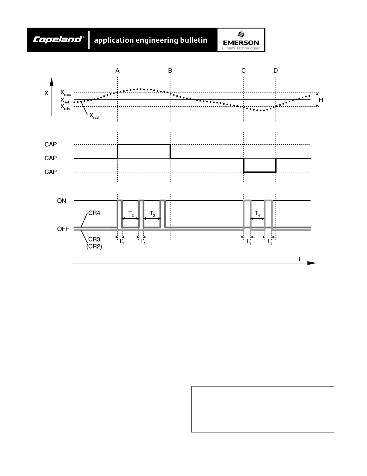
Rigid mounting of the compressor is possible. The use
of anti-vibration mountings especially matched to the
compressors is recommended, however, to reduce the
transmission of body radiated noise.
With direct mounting on water cooled condensers:
CAUTION!CAUTION!
CAUTION!
CAUTION!CAUTION!
Do not mount the compressor directlyDo not mount the compressor directly
Do not mount the compressor directly
Do not mount the compressor directlyDo not mount the compressor directly
on the condenseron the condenser
on the condenser
on the condenseron the condenser
condenser structural mmember! condenser structural mmember!
condenser structural mmember!
condenser structural mmember! condenser structural mmember!
Damage of the condenser is possibleDamage of the condenser is possible
Damage of the condenser is possible
Damage of the condenser is possibleDamage of the condenser is possible
(fatigue fractures). Use anti-vibration (fatigue fractures). Use anti-vibration
(fatigue fractures). Use anti-vibration
(fatigue fractures). Use anti-vibration (fatigue fractures). Use anti-vibration
mountings!mountings!
mountings!
mountings!mountings!
The installation of the anti-vibration mountings is shown
in figure 5. The bolts should only be tightened until
slight deformation of the upper rubber disc is just
visible.
7
. Do not use the. Do not use the
. Do not use the
. Do not use the. Do not use the
Page 8

4.2 System layout4.2 System layout
4.2 System layout
4.2 System layout4.2 System layout
Oil heaterOil heater
Oil heater
Oil heaterOil heater
AE4-1322
The compressor is installed in the refrigerating circuit
similar to semi-hermetic reciprocating compressors.
Plant design and pipe layoutPlant design and pipe layout
Plant design and pipe layout
Plant design and pipe layoutPlant design and pipe layout
The pipelines and the system layout must be arranged
so that the compressor cannot be flooded with oil or
liquid refrigerant during shutdown.
Suitable measures are (also as a simple protection
against liquid slugging during start)
• either to raise the suction line after the evaporator
(goose neck)
• or to install the compressor above the evaporator.
Additional safety is provided by a solenoid valve
installed directly before the expansion valve. In addition
the discharge line should first be angled downwards
after the shut-off valve.
Due to the low level of vibration and discharge gas
pulsation the suction and discharge lines can be made
without the use of flexible elements or mufflers.
However, pipelines must be sufficiently flexible and
supported to not exert any strain on the compressor.
The most favorable pipe runs are designed parallel to
the compressor axis and the discharge line first
leading downwards. The distance to the axis should be
as short as possible and the parallel pipe section
should be at least half the compressor’s length.
Finally, long radius elbows should be used.
Due to gas pulsations there can be vibrations especially in discharge and economizer lines. Therefore
critical pipe lengths (+/- 15%) with their natural frequencies being in resonance with the compressor
pulsations must be avoided.
An oil heater is provided to prevent too high a concentration of refrigerant in the oil during shutdown. It is
mounted in a heater sleeve and can be replaced if
necessary without accessing the refrigerating circuit.
For electrical connection see section 6.4.
Figure 6
Typical system design
Additional insulation of the oil separatorAdditional insulation of the oil separator
Additional insulation of the oil separator
Additional insulation of the oil separatorAdditional insulation of the oil separator
Operation at low ambient temperatures or at high
temperatures on the discharge side during standstill
(such as heat pumps) requires additional insulation of
the oil separator.
Among other things the operating conditions and the
refrigerant (sonic speed) as well as the compressor’s
pulsation frequency must be considered in the calculation.
The base frequency of the compressor is approx.
250Hz (50Hz network) or 300 Hz (60 Hz network).
Frequencies of higher orders (500 / 1000 Hz or 600 /
1200 Hz) should also reviewed at in the final layout.
© 2002 Copeland Corporation
Issued 4-2002
Printed in U.S.A.
Filter drierFilter drier
Filter drier
Filter drierFilter drier
Generously sized filter driers of suitable quality should
be used to ensure a high degree of dehydration and to
maintain the chemical stability of the system.
Suction side cleaning filterSuction side cleaning filter
Suction side cleaning filter
Suction side cleaning filterSuction side cleaning filter
The use of a suction side filter (filter mesh 25 m) will
protect the compressor from damage due to dirt from
the system and is strongly recommended for site built
systems.
8
Page 9

AE4-1322
Expansion valve and evaporatorExpansion valve and evaporator
Expansion valve and evaporator
Expansion valve and evaporatorExpansion valve and evaporator
Expansion valve and evaporator have to be adjusted
using utmost care. This is especially important for
those systems that cover a large control range, e.g.
100% to 25%. In each case, sufficient suction gas
superheat and stable operating conditions must be
assured in full load as well as part load modes.
Depending on the evaporator’s design and performance
range several circuits may be necessary each with
separate expansion and solenoid valves.
3.3 Guidelines for special system variations3.3 Guidelines for special system variations
3.3 Guidelines for special system variations
3.3 Guidelines for special system variations3.3 Guidelines for special system variations
Pump down circuitPump down circuit
Pump down circuit
Pump down circuitPump down circuit
If the evaporator and / or the suction line can become
warmer than the compressor during shutdown, a “pump
down” cycle must be incorporated in addition to the oil
heater.
Additional check valve in the discharge line andAdditional check valve in the discharge line and
Additional check valve in the discharge line and
Additional check valve in the discharge line andAdditional check valve in the discharge line and
automatic sequence controlautomatic sequence control
automatic sequence control
automatic sequence controlautomatic sequence control
For systems with multi-circuit condensers and / or
evaporators, an increased danger exists when individual circuits are shut off. During this period liquid
refrigerant can migrate into the evaporator (no temperature and pressure equalization possible). In these
cases an additional check valve must be installed in
the discharge line. In addition the compressors should
be operated with an automatic sequence control.
The same is also valid for individual systems without
temperature and pressure equalization during longer
shutdown. In extreme cases a suction accumulator or
“pump down” cycle can also become necessary.
Additional oil level controlAdditional oil level control
Additional oil level control
Additional oil level controlAdditional oil level control
accumulator is recommended to protect against liquid
slugging. To effectively avoid increased oil carry-over
(such as due to a rapid decrease of pressure in the oil
separator), the oil temperature must remain at least
54° F above the condensing temperature during charge
over. In addition, it may be necessary to install a
pressure regulator immediately after the oil separator
to limit pressure drop. Under certain conditions it is
also possible to turn off the compressor shortly before
the change over procedure and to restart after pressure
equalization. It must however be assured that the
compressor is operating with the required minimum
pressure differential no longer than 30 seconds (see
application ranges Section 9).
3.4 Additional cooling by means of direct liquid3.4 Additional cooling by means of direct liquid
3.4 Additional cooling by means of direct liquid
3.4 Additional cooling by means of direct liquid3.4 Additional cooling by means of direct liquid
injectioninjection
injection
injectioninjection
Additional cooling is required in areas of high condensing and / or low evaporating temperatures. A relatively
simple method is direct liquid inject at the economizer
connection.
The following criteria must be followed to ensure
reliable operation and to avoid excessive dilution of the
oil.
Liquid inject valveLiquid inject valve
Liquid inject valve
Liquid inject valveLiquid inject valve
Specially designed expansion valves are only suitable
for liquid injection. They must control the discharge
temperature to setting of 190°F (e.g. Danfoss TEAT20,
also series 935-101-B, Sporian Y1037).
The valve bulb must be mounted on the discharge line:
• Clean the tubes surface carefully to bright metal.
Distance from discharge shut-off valve approx. 8 to
10 inches.
The above guidelines also apply to systems with long
pipelines (suchas a remote evaporator and / or condenser). In addition the compressor must be equipped
with an oil level switch (accessory). For electrical
connection see Section 6.4.
Systems with reverse cycling and hot gas defrostSystems with reverse cycling and hot gas defrost
Systems with reverse cycling and hot gas defrost
Systems with reverse cycling and hot gas defrostSystems with reverse cycling and hot gas defrost
These system layouts require individually system
design review to protect the compressor against liquid
slugging and increased oil carry-over. A suction
© 2002 Copeland Corporation
Issued 4-2002
Printed in U.S.A.
• Apply heat transfer paste to the contact surface.
• Fix the bulb firmly with adequate pipe clips. Mind
heat expansion!
• Insulate the bulb and the section of discharge line
9
Page 10

AE4-1322
Pipe runsPipe runs
Pipe runs
Pipe runsPipe runs
To ensure a bubble free liquid supply to the liquid
injection valve, the connection must be made on the
bottom of a horizontal section of the liquid line.
Installation of the liquid inject valve at the com-Installation of the liquid inject valve at the com-
Installation of the liquid inject valve at the com-
Installation of the liquid inject valve at the com-Installation of the liquid inject valve at the compressorpressor
pressor
pressorpressor
• Min. 6 to 8 in. above liquid injection connection
CAUTION!CAUTION!
CAUTION!
CAUTION!CAUTION!
VV
ibration fractures possible! install liquidibration fractures possible! install liquid
V
ibration fractures possible! install liquid
VV
ibration fractures possible! install liquidibration fractures possible! install liquid
injection and solenoid valves withinjection and solenoid valves with
injection and solenoid valves with
injection and solenoid valves withinjection and solenoid valves with
adequate supports!adequate supports!
adequate supports!
adequate supports!adequate supports!
Check for vibration during operation!Check for vibration during operation!
Check for vibration during operation!
Check for vibration during operation!Check for vibration during operation!
Calculating the cooling capacity of the liquidCalculating the cooling capacity of the liquid
Calculating the cooling capacity of the liquid
Calculating the cooling capacity of the liquidCalculating the cooling capacity of the liquid
injection valveinjection valve
injection valve
injection valveinjection valve
Figure 7
Liquid injection valve (system design)
• With the selection software
• Consider the most extreme conditions to be
expected during actual operation:
- min. evaporating temperature
- max. suction gas superheat and condensing
temperature
Further conditions for valve selectionFurther conditions for valve selection
Further conditions for valve selection
Further conditions for valve selectionFurther conditions for valve selection
• Pressure at the injection point:
- R134a approximately 30 to 45 psig above
suction pressure R407C, R22 approx. 40 to
50 psig above suction pressure
- Never size the valve too large danger of
refrigerant flooding!
Additional components in the liquid lineAdditional components in the liquid line
Additional components in the liquid line
Additional components in the liquid lineAdditional components in the liquid line
• Solenoid valve (energized parallel to compressor
contactor)
• Filter dryer (if required)
• Liquid sight glass
© 2002 Copeland Corporation
Issued 4-2002
Printed in U.S.A.
10
Page 11

3.5 Additional cooling by means of external oil3.5 Additional cooling by means of external oil
3.5 Additional cooling by means of external oil
3.5 Additional cooling by means of external oil3.5 Additional cooling by means of external oil
coolercooler
cooler
coolercooler
AE4-1322
• Oil coolers must be controlled by thermostats (see
table for temperature settings).
The application of an external oil cooler (air, water or
refrigerant cooled) instead of refrigerant inject provides
additional extension of the application envelopes and
even better efficiency.
When calculating an oil cooler, worst case operating
conditions must be used:
• Min. evaporating temperature
• Max. suction gas superheat
• Max. condensing temperature
• Operation mode (capacity control, ECO)
Oil cooler capacity can be calculated by using the
selection software.
Recommendations for external oil coolersRecommendations for external oil coolers
Recommendations for external oil coolers
Recommendations for external oil coolersRecommendations for external oil coolers
• Connections for external oil coolers are located on
the back side of the compressor below the discharge shut-off valve (oval or rectangular flange).
The flange is replaced by a tube adaptor (option):
• Install oil cooler as close as possible to the compressor.
• Piping design must avoid gas pockets and any
drainage of oil into the compressor during shutdowns (installation of the oil cooler preferably at
compressor level or below).
• For rapid heating of the oil circuit and minimizing
the pressure drop with cold oil an oil by-pass (or
even heating the cooler during shut down) is
required under the following conditions:
- the oil temperature in the cooler drops below
60°F during shut down,
- the oil volume of cooler plus oil piping exceeds
the compressor’s oil charge,
- The oil cooler is an integral part of the con-
denser coil
• The by-pass valve should have a temperature
responsive modulating control function. The use of a
solenoid valve for intermittent control would require
highly sensitive control thermostat and a minimal
switching differential (effective temperature variation
< 18°F).
• The oil side pressure drop during normal operation
should not exceed 7 psig.
• Due to the additional oil volume (cooler, piping) a
solenoid valve may be necessary in the oil line.
This is to avoid oil migration into the compressor
during shutdowns. The solenoid valve must be
installed close to the compressor’s oil inlet connection and its electric control should be parallel to the
contactor’s normally open contact. Recommended
additional components:
- Sight glass to check oil flow,
- Manual shut-off ball valves in both feed and
return lines for ease of service,
- Oil filter (max. 25 µ mesh size)
With an additional oil volume (cooler and piping) of
10% of the compressor’s standard oil charge and
assured cleanliness of components and pipes the
above mentioned measures can be omitted.
© 2002 Copeland Corporation
Issued 4-2002
Printed in U.S.A.
Figure 8
External oil cooler connection
Water cooled oil coolerWater cooled oil cooler
Water cooled oil cooler
Water cooled oil coolerWater cooled oil cooler
Temperature control by thermostatic water regulator
(for set point see table, required sensor temperature
should be equal to or greater than 250°F).
11
Page 12

Figure 9
Water-cooled oil cooler
Air cooled oil coolerAir cooled oil cooler
Air cooled oil cooler
Air cooled oil coolerAir cooled oil cooler
Temperature control by thermostatic switching on and
off or stepless speed control of the cooler fan (see
table for set point, required sensor temperature should
be equal to or greater than 250°F).
AE4-1322
Thermosyphon oil cooling (cooling by refrigerant)Thermosyphon oil cooling (cooling by refrigerant)
Thermosyphon oil cooling (cooling by refrigerant)
Thermosyphon oil cooling (cooling by refrigerant)Thermosyphon oil cooling (cooling by refrigerant)
Temperature control either by thermostatic regulation
valve for refrigerant feed or by-pass valve (see table for
set point; admissible operating and sensor temperature
should be equal to or greater than 250°F).
As an example figure 11 shows a layout with a primary
receiver after the condenser. An alternative layout of the
thermosyphon circuit as well as refrigerant circulation
by means of a pump or an ejection is also possible
(information upon request).
If the oil coolers is integrated into the condenser the
by-pass valve controls the temperature (see table for
set point; admissible operating and / or sensor temperature should be equal to or greater than 250°F).
DL SL
Figure 10
Air cooled oil coolers
Figure 11
Thermosyphon oil cooling
4 Economizer operation
1.1 General1.1 General
1.1 General
1.1 General1.1 General
SCH2/SCA2 screw compressors are designed for
economizer operation “ECO”. With this operation mode
both cooling capacity and efficiency are improved by
means of a sub-cooling circuit or 2-stage refrigerant
expansion. There are capacity and efficiency advantages in ECO operation over the conventional application, particularly at high condensing temperatures.
A unique feature of the compact screws is the economizer channel integrated into the control slide (fig.12).
This enables to operate the sub-cooling circuit regardless of the compressor load condition. Screw compressors with a fixed ECO suction position have this
frequently located in the suction area of the rotors
during part load and then has no effect.
© 2002 Copeland Corporation
Issued 4-2002
Printed in U.S.A.
12
Page 13

5.2 Operation principle5.2 Operation principle
5.2 Operation principle
5.2 Operation principle5.2 Operation principle
AE4-1322
5.3 Economizer operation with sub-cooling circuit5.3 Economizer operation with sub-cooling circuit
5.3 Economizer operation with sub-cooling circuit
5.3 Economizer operation with sub-cooling circuit5.3 Economizer operation with sub-cooling circuit
With screw compressors the compression process
occurs only in one flow direction (see Section 2.2).
This fact enables to locate an additional suction port at
the rotor housing. The position is selected so that the
suction process has already been completed and a
slight pressure increase has taken place. Via this
connection an additional mass flow can be taken in,
which has only a minimal effect on the flow from the
suction side.
The pressure level at the ECO suction point is similar
to the intermediate pressure with 2-stage compressors. This means that an additional sub-cooling circuit
or intermediate pressure receiver for 2-stage expansion
can be integrated into the system. This design
achieves a significantly higher cooling capacity through
additional liquid sub-cooling. At the same time, there is
a relatively low increase in the compressor’s power
input, as the total working process becomes more
efficient – due to the higher suction pressure, among
other things.
System with sub-cooling circuit
Figure 12
With this operation mode a heat exchanger is utilized
as a liquid sub-cooler. A part of the refrigerant mass
flow from the condenser enters the sub-cooler via an
expansion device, and evaporates upon absorbing heat
from the counter-flowing liquid refrigerant (sub-cooling).
The superheated vapor is taken in at the compressor’s
ECO connection, mixed with the mass flow from the
evaporator and compressed to a high pressure.
With this type of operation the sub-cooled liquid is
under condensing pressure. Therefore the piping to the
evaporator does not require any special features –
apart from insulation.The system can be applied
universally.
5.4 ECO operation with intermediate pressure5.4 ECO operation with intermediate pressure
5.4 ECO operation with intermediate pressure
5.4 ECO operation with intermediate pressure5.4 ECO operation with intermediate pressure
receiverreceiver
receiver
receiverreceiver
This layout version for 2-stage refrigerant pressure relief
is particularly advantageous in connection with flooded
evaporators and is therefore primarily used in plants
with large cooling capacity.
© 2002 Copeland Corporation
Issued 4-2002
Printed in U.S.A.
13
Page 14

5.5 Layout and selection recommendations5.5 Layout and selection recommendations
5.5 Layout and selection recommendations
5.5 Layout and selection recommendations5.5 Layout and selection recommendations
Pipe layoutPipe layout
Pipe layout
Pipe layoutPipe layout
• Design the sub-cooler so that during shutdown,
neither liquid refrigerant nor oil can enter the compressor.
• Until operating conditions are established during
temporary operation without economizer and when
switching off the compressor, the compressor can
discharge a certain amount of oil through the ECO
connection. Oil transfer into the sub-cooler must
therefore be prevented by a pipe bending vertically
upwards with a check valve (see fig.13).
In order to avoid instability of the check valve when
the ECO circuit is switched off, a by-pass-line with a
solenoid valve towards the suction side must also be
included (1/4”). The solenoid valve is only open when
the ECO is not operating. This way it creates
sufficient closing pressure for the check valve.
AE4-1322
• Pipe vibrations:
Due to the pulsations emitting from the profile area
of the compressor, critical pipe lengths must be
avoided. See also Section 4.2.
5.6 Additional components5.6 Additional components
5.6 Additional components
5.6 Additional components5.6 Additional components
Refrigerant sub-coolerRefrigerant sub-cooler
Refrigerant sub-cooler
Refrigerant sub-coolerRefrigerant sub-cooler
Frost proof shell and tube, coaxial or plate heat
exchangers are suitable as sub-coolers. In the design
phase the relatively high temperature gradient on the
liquid side must be taken into consideration.
For capacity determination see output date in the
compressor software:
• Sub-cooler capacity
• ECO mass flow
• Saturated ECO temperature and
• Liquid temperature.
Layout parametersLayout parameters
Layout parameters
Layout parametersLayout parameters
• See Section 6 for electric control. Other layout
versions are also possible, but must be checked for
their suitability and operating safety in individual
tests.
• The ECO connection leads directly into the profile
area. For this reason a high degree of cleanliness
must be maintained for sub-cooler and pipes.
• Dimension of the ECO suction line:
In view of the usually short pipe lengths, the following
pipe diameters can be used:
SCH2 5000 to 9000 1 ¼” – 12 Rotolock
SCA2 3500 to 7000
SCH2 11H0 to 14H0 1 ½” – 12 Rotolock
SCA2 9000 to 11H0
Min 6 – 8” rise
• Intermediate temperature
- corresponds to the evaporating temperature in
the sub-cooler
- for layout design, take 18°F suction gas
superheat into consideration
• Liquid temperature (inlet)
As a nominal selection basis, liquid sub-cooling of
4°F is assumed
example:
tc = 90°F liquid temperature (inlet) = 86ºF.
• Liquid temperature (outlet) The software pre-set
date are based on 18°F above saturated ECO
temperature
Example:
tm = +68ºF liquid temperature (outlet) = 86ºF
Input of individual data is possible. Keep in mind,
however, that in practice a stable operating mode is
very difficult to achieve with differences between
liquid temperature (outlet) and saturated ECO
temperature of less than 18°F.
Figure 13
Liquid injection connections
© 2002 Copeland Corporation
Issued 4-2002
Printed in U.S.A.
14
Page 15

Thermostatic expansion valvesThermostatic expansion valves
Thermostatic expansion valves
Thermostatic expansion valvesThermostatic expansion valves
• Valve layout for liquid sub-cooler:
- Basis is the sub-cooling capacity
- Evaporating temperature corresponds to the
ECO intermediate temperature.
- Valves with a superheat adjustment of about 10
K should be used in order to avoid unstable
operation when switching on the sub-cooling
circuit and in connection with load fluctuations.
- If the sub-cooling circuit is also operated under
part-load conditions, this must be given due
consideration when designing the valves.
• Valve layout for evaporator:
Due to the high degree of liquid sub-cooling suction
mass flow is much lower than with systems with
similar capacity and no sub-cooler (see software
data). This requires a modified layout. In this
context the lower vapor content after expansion
must also be taken into consideration. For further
hints on the layout of expansion valves and evaporators see Section 4.2.
5.7 Control5.7 Control
5.7 Control
5.7 Control5.7 Control
Between that start and the stabilization of operating
conditions, the solenoid valve of the sub-cooling circuit
is switched on time delayed or depending on suction
pressure. For further hints and a schematic layout
diagram see Section 6.4.
AE4-1322
The compressors are supplied as standard with part
winding motors of connection (Part Winding “PW”).
Start delta motors are available as special design.
Part winding motorsPart winding motors
Part winding motors
Part winding motorsPart winding motors
Starting methods (connections according to figures 14
and 15):
• Part winding start to reduce the starting current
• Direct on line start (DOL)
Start delta motorsStart delta motors
Start delta motors
Start delta motorsStart delta motors
Starting methods (connections according to figures 16
and 17).
The start current value in star mode (1/3 ofThe start current value in star mode (1/3 of
The start current value in star mode (1/3 of
The start current value in star mode (1/3 ofThe start current value in star mode (1/3 of
the direct on line value) is generally statedthe direct on line value) is generally stated
the direct on line value) is generally stated
the direct on line value) is generally statedthe direct on line value) is generally stated
according to standard locked rotor condi-according to standard locked rotor condi-
according to standard locked rotor condi-
according to standard locked rotor condi-according to standard locked rotor conditions. In realitytions. In reality
tions. In reality
tions. In realitytions. In reality
obtained during the start. Moreoverobtained during the start. Moreover
obtained during the start. Moreover
obtained during the start. Moreoverobtained during the start. Moreover
switching from start to delta mode there is aswitching from start to delta mode there is a
switching from start to delta mode there is a
switching from start to delta mode there is aswitching from start to delta mode there is a
current peak as high as the direct start value.current peak as high as the direct start value.
current peak as high as the direct start value.
current peak as high as the direct start value.current peak as high as the direct start value.
This is caused by the voltage interruptionThis is caused by the voltage interruption
This is caused by the voltage interruption
This is caused by the voltage interruptionThis is caused by the voltage interruption
during switch-over of the contactors, whichduring switch-over of the contactors, which
during switch-over of the contactors, which
during switch-over of the contactors, whichduring switch-over of the contactors, which
results in a speed drop due to theresults in a speed drop due to the
results in a speed drop due to the
results in a speed drop due to theresults in a speed drop due to the
compressorcompressor
compressor
compressorcompressor
, however, however
, however
, however, however
’’
s small rotating masses.s small rotating masses.
’
s small rotating masses.
’’
s small rotating masses.s small rotating masses.
, approx. 50% are, approx. 50% are
, approx. 50% are
, approx. 50% are, approx. 50% are
, when, when
, when
, when, when
6 Electrical connection6 Electrical connection
6 Electrical connection
6 Electrical connection6 Electrical connection
6.1 Motor design6.1 Motor design
6.1 Motor design
6.1 Motor design6.1 Motor design
Figure 14
© 2002 Copeland Corporation
Issued 4-2002
Printed in U.S.A.
Figure 15
15
Figure 16
Figure 17
Page 16

Figure 18
Power factor correction on individual compressors
AE4-1322
6.2 Selection of electrical components6.2 Selection of electrical components
6.2 Selection of electrical components
6.2 Selection of electrical components6.2 Selection of electrical components
Cables, contractors and fusesCables, contractors and fuses
Cables, contractors and fuses
Cables, contractors and fusesCables, contractors and fuses
CAUTIONCAUTION
CAUTION
CAUTIONCAUTION
Nominal power is not the same asNominal power is not the same as
Nominal power is not the same as
Nominal power is not the same asNominal power is not the same as
maximum motor power! When selectingmaximum motor power! When selecting
maximum motor power! When selecting
maximum motor power! When selectingmaximum motor power! When selecting
cables, contactors and fuses: cables, contactors and fuses:
cables, contactors and fuses:
cables, contactors and fuses: cables, contactors and fuses:
operating current / maximum motoroperating current / maximum motor
operating current / maximum motor
operating current / maximum motoroperating current / maximum motor
power must be considered. See chapter 8. power must be considered. See chapter 8.
power must be considered. See chapter 8.
power must be considered. See chapter 8. power must be considered. See chapter 8.
Contactor selection: according toContactor selection: according to
Contactor selection: according to
Contactor selection: according toContactor selection: according to
operational category operational category
operational category
operational category operational category
Part winding motorsPart winding motors
Part winding motors
Part winding motorsPart winding motors
The following current values appear in the part windings:
PW1 PW2
50% 50%
Both of the contactors should be selected for at least
60% of the maximum operating current.
Star delta motorsStar delta motors
Star delta motors
Star delta motorsStar delta motors
Calculate mains and delta contactor each to at least
60%, start contactor to 33% of the maximum operating
current.
MaximumMaximum
Maximum
MaximumMaximum
AC 3.AC 3.
AC 3.
AC 3.AC 3.
Power factor correctionPower factor correction
Power factor correction
Power factor correctionPower factor correction
For the reduction of the reactive current when using
inductive loads (motors, transformers), power factor
correction systems (capacitors) are increasingly being
used. However, apart from the undisputed power
supply advantages, experience shows that the layout
and execution of such systems is not a simple matter,
as insulation damage on motors and increased contact
arcing on contactors can occur.
With a view to a safe operating mode, the correction
system should be designed to effectively prevent “overcorrection” in all operating conditions and the uncontrolled discharge of the capacitors when starting and
shutting down the motors.
General design criteriaGeneral design criteria
General design criteria
General design criteriaGeneral design criteria
• Maximum power factor (P.F. 0.95 - taking into
consideration all load conditions.)
Individual correction (Fig. 21)Individual correction (Fig. 21)
Individual correction (Fig. 21)
Individual correction (Fig. 21)Individual correction (Fig. 21)
• With capacitors that are directly fitted to the motor
(without the possibility of switching off with
contactors), the capacitor capacity must never be
greater than 90% of the zero-load reactive capacity
of the motor (less than 25% of max. motor power).
With higher capacities there is the danger of selfexiting when shutting off, resulting in damage to the
motor.
© 2002 Copeland Corporation
Issued 4-2002
Printed in U.S.A.
16
Page 17

AE4-1322
• For part winding start a separate capacitor should
be used for each half of the winding (50% each).
Only one capacitor is used for start delta motors
(parallel to contactor K1).
• In the case of extreme load fluctuations (large
capacity range) combined with high demands on a
low reactive capacity, capacitors that can be
switched on and off with contactors (in combination
with a discharge throttle) may be necessary.
Design is similar to central correction.
Central correction (Fig. 22)Central correction (Fig. 22)
Central correction (Fig. 22)
Central correction (Fig. 22)Central correction (Fig. 22)
• When the designing, connected loads and the
operating times of all inductive loads (including
fluorescent lamps if they do not have their own
correction) must be taken into consideration.
• The number of capacitor stages must be selected
so that the smallest unit does not have a larger
capacity than the lowest inductive load (with P.F.
0.95). Extreme part load conditions are particularly
critical, such as can occur during the night, at
weekends or while being put into operation. If loads
are too low the entire correction device should be
disconnected from the power supply.
• With central correction (as well as with individual
correction with contactor control) discharge throttle
must always be provided. Reconnection to the
power supply may only occur after complete
discharge and a subsequent time delay.
The layout of correction systems for motors with
direct starting is similar.
CAUTION!CAUTION!
CAUTION!
CAUTION!CAUTION!
It is essential to observe the generalIt is essential to observe the general
It is essential to observe the general
It is essential to observe the generalIt is essential to observe the general
design and layout instruction of thedesign and layout instruction of the
design and layout instruction of the
design and layout instruction of thedesign and layout instruction of the
correction system manufacturer correction system manufacturer
correction system manufacturer
correction system manufacturer correction system manufacturer
Frequency inverterFrequency inverter
Frequency inverter
Frequency inverterFrequency inverter
Operation with a frequency inverter is possible. However, layout and operating conditions must be individually approved by Copeland
3.3 Compressor protection system3.3 Compressor protection system
3.3 Compressor protection system
3.3 Compressor protection system3.3 Compressor protection system
The SCH2/SCA2 compressors are fitted with the
protection device INT69VSY-II.
Monitoring functionsMonitoring functions
Monitoring functions
Monitoring functionsMonitoring functions
• Winding temperature (PTC sensors in motor
winding)
- Interruption of the control current with excess
temperature
- Manual reset (after winding has cooled) by
interruption of supply voltage L/N for at least
2 seconds
• Oil temperature (sensor with PTC resistance in oil
sump)
- Function as above (winding temperature)
..
.
..
..
.
..
© 2002 Copeland Corporation
Issued 4-2002
Printed in U.S.A.
Figure 20
Power factor correction on central power system
17
Page 18

• Direction of rotation/phase sequence (direct measurement at compressor terminals)
- Immediate interruption of control current and
lock-out with wrong direction of rotation / phase
sequence (indication via signal contact 12)
- Reset (after correction of fault) by interruption of
the supply voltage L/N for at least 2 seconds.
The protection device is built into the terminal box.
The wiring to the motor and oil temperature PTC
sensors and also to be motor terminals is factory
mounted. The electrical connections to the device
should be made according to figure 21 or 22 and the
schematic wiring diagrams.
In principle the device could be also built into the
control panel. In the case it is essential to adhere to
the following recommendations:
Special attention must be given when fitting the
INT69VSY-II in the control panel:
AE4-1322
CAUTIONCAUTION
CAUTION
CAUTIONCAUTION
Make sure that the rotation monitoring isMake sure that the rotation monitoring is
Make sure that the rotation monitoring is
Make sure that the rotation monitoring isMake sure that the rotation monitoring is
functioning! Tfunctioning! T
functioning! T
functioning! Tfunctioning! T
INT69VSYINT69VSY
INT69VSY
INT69VSYINT69VSY
according to the wiring diagram. according to the wiring diagram.
according to the wiring diagram.
according to the wiring diagram. according to the wiring diagram.
the jumper L/D1 at this time.the jumper L/D1 at this time.
the jumper L/D1 at this time.
the jumper L/D1 at this time.the jumper L/D1 at this time.
The following requirements must be ensured byThe following requirements must be ensured by
The following requirements must be ensured by
The following requirements must be ensured byThe following requirements must be ensured by
the control logic:the control logic:
the control logic:
the control logic:the control logic:
• Minimum time of standstill: 1 minute. Valid during
maintenance also!
Returning time of the control slide - CR3 (Y3)
energized
• Maximum cycling rate 6 to 8 starts per hour!
• Minimum running time desired 5 minutes!
• Switch-over time part winding 0.5 seconds start
delta 1 second
erminal D1 of theerminal D1 of the
erminal D1 of the
erminal D1 of theerminal D1 of the
-II must be connected-II must be connected
-II must be connected
-II must be connected-II must be connected
RemoveRemove
Remove
RemoveRemove
• The connecting cables to the motor terminals must
be wired in the sequence described (L1 to terminal
“1” etc.) Check with a direction of rotation indicator!
• Danger of induction!
Only use shielded cables or a twisted pair to
connect to the PTC motor sensors and oil temperature PTC sensors.
• Additional fuses (4 A) must be incorporated in the
connecting cables between “L1/L2/L3” of the
protection device and the motor terminals “1/2/3”.
• The terminals T1-T2 on the compressor and 1-2 on
protection device must not come into contact with
supply or control voltage.
CAUTIONCAUTION
CAUTION
CAUTIONCAUTION
If the rotation direction is wrong: DangerIf the rotation direction is wrong: Danger
If the rotation direction is wrong: Danger
If the rotation direction is wrong: DangerIf the rotation direction is wrong: Danger
of severe compressor damage! of severe compressor damage!
of severe compressor damage!
of severe compressor damage! of severe compressor damage!
6.4 Schematic wiring diagrams6.4 Schematic wiring diagrams
6.4 Schematic wiring diagrams
6.4 Schematic wiring diagrams6.4 Schematic wiring diagrams
The following schematic wiring diagrams show examples of application for
start each with infinite and 4-step capacity con-start each with infinite and 4-step capacity con-
start each with infinite and 4-step capacity con-
start each with infinite and 4-step capacity con-start each with infinite and 4-step capacity control.trol.
trol. In addition optional control schemes for liquid
trol.trol.
injection, economizer operation and oil level controls
are included.
© 2002 Copeland Corporation
Issued 4-2002
Printed in U.S.A.
part winding and star deltapart winding and star delta
part winding and star delta
part winding and star deltapart winding and star delta
Instruction for start delay timer with economizerInstruction for start delay timer with economizer
Instruction for start delay timer with economizer
Instruction for start delay timer with economizerInstruction for start delay timer with economizer
operationoperation
operation
operationoperation
The switching-on device F7 must ensure that the
refrigerant flow to the liquid sub-cooler is not switched
on until operating conditions have sufficiently stabilized. This is achieved by using the solenoid valve Y6.
With frequent starting from high suction pressure, a
pressure switch should be sued. The set point should
be sufficiently above the nominal evaporating temperature in order to prevent the economizer solenoid valve
Y6 from short cycling.
For systems with relatively constant pull down cycles
(such as liquid chillers), an alternative is to use a time
relay. The delay time must then be checked individually for each individual systems.
LegendLegend
Legend
LegendLegend
B2 Control Unit
F1 Main fuse
F2 Compressor fuse
F3 Control circuit fuse
F4 Control circuit fuse
F5 High pressure cut out
F6 Low pressure cut out
F7 Start delay timer “Economizer”
F8 Oil level switch (option)
F13 Thermal overload “motor” PW1
18
Page 19

AE4-1322
F14 Thermal overload “motor” PW2
H1 Signal lamp “motor fault” (over temp / phase
failure)
H4 Signal lamp “oil level fault”
K1 Contactor “first PW” (for PW) “Mains contactor”
(Y/)
K2 Contactor “second PW” (PW) “Start contactor”
(Y)
K3 “Delta contactor” (Y))
K4 Auxiliary contactor (option)
K2T Time relay “pause time”
K3T Time relay “part winding: or “star delta”
K4T Time relay “oil level switch”
K5T Fixed pulse relay “CR4” flashing function on / off
10 seconds
M1 Compressor
Q1 Main switch
R1 Oil heater *
R2 Oil temperature sensor (PTC) *
R3-8 Motor PTC sensor *
S1 On-off switch
S2 Fault reset “motor & discharge temperature”
and/or “direction of rotation”
S4 Fault reset “oil level”
U Screening unit (if required, such as from Murr
Elektronik)
Y1 SV “capacity control” *
Y2 SV “capacity control” *
Y3 SV “capacity control” *
Y4 SV “capacity control” *
Y5 SV “liquid line”
Y6 SV “refrigerant injection” alternatively
“econimizer”
Y7 SV “economizer by-pass” INT69VSY-II
Control device for motor protection and dis
charge gas superheat protection *
SV Solenoid valve
* Parts are included with compressor
Capacity control
Y1 CR1, Y2 CR2
Y3 CR3, Y4 CR4
Figure 21
Part winding start wiring diagram
© 2002 Copeland Corporation
Issued 4-2002
Printed in U.S.A.
19
Page 20

AE4-1322
Figure 23
Part winding start options
Figure 22
Part winding start with 4-step capacity control
© 2002 Copeland Corporation
Issued 4-2002
Printed in U.S.A.
20
Page 21

Data for accessories and oil chargeData for accessories and oil charge
Data for accessories and oil charge
Data for accessories and oil chargeData for accessories and oil charge
Liquid sub-coolingLiquid sub-cooling
Liquid sub-cooling
Liquid sub-coolingLiquid sub-cooling
AE4-1322
• Oil heater: 115/230 VAC
SCH2 5000 to 9000 200W
SCA2 3500 to 7000
SCH2 11H0 to 14H0 300W
SCA2 9000 to 11H0
• Capacity control:
24/115/230 VAC 50/60 Hz
• Oil charge:
Solest170 for R134a, R407C, R404A and R507A
CP4214-320 for R 22
Oil heaterOil heater
Oil heater
Oil heaterOil heater
Ensures the lubricity of the oil even during long standstill periods. It prevents increased refrigerant dilution
into the oil and therefore reduction of viscosity.
The oil heater must be used during the shutdown for
• outdoor installation of the compressor (insulate the
oil separator additionally if necessary)
• long off cycles
• high refrigerant charge
• danger of refrigerant condensation into the
compressor
10 Performance data10 Performance data
10 Performance data
10 Performance data10 Performance data
For detailed compressor selection with the option of
individual data input our selection software is available
as CD-ROM or can be downloaded from our internet
web site. The resulting output data include all important performance parameters for compressors and
additional components, application ranges, technical
data and dimensional drawings. Moreover, specific data
sheets can be generated which may either be printed
out or transferred into other software programs, such
as Excel, for further use.
Basic parametersBasic parameters
Basic parameters
Basic parametersBasic parameters
Evaporating and condensing temperatures correspond
to “dew point” conditions (saturated vapor). With
zeotropic blends like R407C this leads to a change in
the basic parameters (pressure levels, liquid temperatures) compared with data according to “intermediate
temperatures” used so far. As a consequence this
results in a lower numerical value for cooling capacity
and efficiency (COP).
With standard conditions
nono
no liquid sub-cooling is
nono
considered. Therefore the rated cooling capacity and
efficiency (COP) show lower values in comparison to
data based on 9 or 15°F of sub-cooling.
Economizer operationEconomizer operation
Economizer operation
Economizer operationEconomizer operation
Data for economizer operation system inherently
include liquid sub-cooling. The liquid temperature is
defined as 18°F above saturated temperature (dew
point with R407C) at economizer inlet (t
= tms +
cu
18°F).
10.1 Compressor selection by software10.1 Compressor selection by software
10.1 Compressor selection by software
10.1 Compressor selection by software10.1 Compressor selection by software
• Select the menu
CSH Compact Screws.
• Type the desired Cooling Capacity.
• Select desired operating conditions:
-Refrigerant and for R407C
-Reference temperature
-Evaporating temperature
-Condensing temperature
-Without or with economizer
-Liquid Sub-cooling
-Suction Gas superheat or suction gas temp.
-Useful superheat
-Power supply
• Hit Calculate.
In the window Output Data the selected compressors with performance data are shown (fig. 24).
• Data output:
At this stage an input of individual text (Head line)
is possible.
- Print: Print-out at standard printer, with
application limits (application ranges)
- Export: Output as ASCII file
10.2 Finding compressor performance data using10.2 Finding compressor performance data using
10.2 Finding compressor performance data using
10.2 Finding compressor performance data using10.2 Finding compressor performance data using
the softwarethe software
the software
the softwarethe software
• Select the menu CSH Compact Screws.
• Select Compressor Type.
© 2002 Copeland Corporation
Issued 4-2002
Printed in U.S.A.
21
Page 22

• Select the desired operating conditions:
- Refrigerant and for R407C reference
temperature
- Evaporating temperature
- Without or with economizer
- UCT. gas superheat or suction gas
temperature
- Useful superheat
- Capacity regulator
- Power supply
• Hit
Calculate.
In the window Output Data the selected compressor
with performance data is shown.
• Data output:
at this stage an input of individual text (Head line)
is possible.
- Print: Print out at standard printer, with applica-
tion limits (application ranges)
- Export: Output as ASCII file
Operating point in application limits diagram
•Hit Limits.
Standard application limits diagram with operating
point (blue cross) is shown in the window.
Further window: application limits diagram for ECO.
AE4-1322
TT
echnical data of a compressorechnical data of a compressor
T
echnical data of a compressor
TT
echnical data of a compressorechnical data of a compressor
• Hit T. Data.
Window Data appears, in which the technical data
are listed.
Further windows:
Dimensions (dimensional drawing and Notes (notes
and legend)
• Export all data with Print (Print-out at standard
printer, or Export (as ASCII file).
Export performance tables
• Hit Tables.
The blank Performance Table is shown in the
window.
• Check the default values (white fields) and change
where necessary.
The Input Values can only be changed in the
window Single Point Calculation.
•Hit Calculate.
The Performance Table is shown in the window.
• Export the data with Print (print-out at standard
printer, Export (as ASCII file) or Copy into the
clipboard).
© 2002 Copeland Corporation
Issued 4-2002
Printed in U.S.A.
22
Copeland is a registered trademark and Copeland
Screw is a trademark of Copeland Corporation. The
Emerson Climate Technologies logo is a trademark and
service mark of Emerson Elelctric Co.
 Loading...