

Emerson Copeland EazyCool ZXDI Series, ZXDI050E, ZXDI060E, ZXDI040E, ZXDI075E Application Manuallines
Page 1

Application Guidelines
Copeland EazyCool
™
Indoor Condensing Units
ZXDI Range
Page 2

C6.1.10/0118-0318/E
About these guidelines ............................................................................................... 1
1 Safety instructions ........................................................................................... 1
1.1 Icon explanation ............................................................................................................... 1
1.2 Safety statements ............................................................................................................ 1
1.3 General instructions ......................................................................................................... 2
2 Product description ......................................................................................... 3
2.1 Common information about Copeland EazyCool™ ZXDI indoor condensing units ........ 3
2.2 EU Ecodesign Directive 2009/125/EC ............................................................................. 3
2.3 Product range .................................................................................................................. 3
2.4 Product nameplate ........................................................................................................... 3
2.5 Nomenclature ................................................................................................................... 3
2.6 Application range ............................................................................................................. 4
2.6.1 Qualified refrigerants and oils .............................................................................. 4
2.6.2 Application limits ................................................................................................... 4
2.7 Bill of material .................................................................................................................. 4
2.8 Main components description .......................................................................................... 4
2.8.1 Compressor .......................................................................................................... 4
2.8.2 Condenser fan(s) .................................................................................................. 5
2.8.3 Housing ................................................................................................................ 6
2.9 P&I diagram for ZXDI units .............................................................................................. 7
2.10 XCM25D Electronic controller – Features ....................................................................... 8
2.10.1 Description ........................................................................................................... 8
2.10.2 Functionality ......................................................................................................... 8
2.10.3 Main control & safety features .............................................................................. 9
2.10.4 Additional features for customization ................................................................. 10
2.11 XCM25D Electronic controller – Programming .............................................................. 12
2.11.1 Programming the local display ........................................................................... 12
2.11.2 Remote display CCM60 ..................................................................................... 13
2.11.3 Single commands ............................................................................................... 14
2.11.4 Double commands – Entering programming level 1 "Pr1" ................................. 14
2.11.5 How to program the parameters (Pr1 and Pr2) .................................................. 14
2.11.6 Entering programming level 2 "Pr2" ................................................................... 15
2.11.7 Fast access menu .............................................................................................. 15
2.12 Controller keyboard ........................................................................................................ 15
2.12.1 How to lock the keyboard ................................................................................... 15
2.12.2 How to unlock the keyboard ............................................................................... 16
2.13 Parameters level 1 – Required settings ......................................................................... 16
2.14 Digital operation ............................................................................................................. 16
2.15 Reset to factory settings – Emerson "Hot Key" ............................................................. 17
2.15.1 How to save factory settings or user settings .................................................... 17
Page 3

C6.1.10/0118-0318/E
2.15.2 Emerson "Hot Key" for ZXDI units with XCM25D controller .............................. 17
2.15.3 Location of the "Hot Key" plug connection on the XCM25D controller .............. 18
2.15.4 How to program a "Hot Key" from the controller (upload) .................................. 18
2.15.5 How to program a controller using an Emerson "Hot Key" (download) ............. 18
2.16 Troubleshooting – Alarm history .................................................................................... 19
2.17 Compressor motor protection ........................................................................................ 19
2.18 System pressure protection ........................................................................................... 19
2.18.1 High-pressure safety switch ............................................................................... 19
2.18.2 High pressure: pressure relief valve ................................................................... 20
2.18.3 Low-pressure safety switch – Optional .............................................................. 20
2.18.4 Ambient temperature sensor .............................................................................. 20
2.19 Alarm output (DO5) ........................................................................................................ 20
2.20 Fan speed control – Ziehl-Abegg PKE-6 controller ....................................................... 20
2.21 Dimensions in mm ......................................................................................................... 21
3 Installation ...................................................................................................... 22
3.1 Condensing unit handling .............................................................................................. 22
3.1.1 Transport and storage ........................................................................................ 22
3.1.2 Weights............................................................................................................... 22
3.2 Electrical connection ...................................................................................................... 23
3.2.1 Power supply connections.................................................................................. 23
3.2.2 Maximum operating currents for cable selection ............................................... 23
3.2.3 Electrical wiring .................................................................................................. 23
3.2.4 Electrical protection standard (protection class) ................................................ 23
3.2.5 Overload protection ............................................................................................ 23
3.3 Refrigeration piping connections ................................................................................... 24
3.3.1 Refrigeration piping installation .......................................................................... 24
3.3.2 Brazing recommendations.................................................................................. 25
3.3.3 Brazing procedure .............................................................................................. 25
3.4 Location & fixings ........................................................................................................... 26
3.5 Required distances ........................................................................................................ 26
3.6 Air ducts connection ....................................................................................................... 27
4 Starting up & operation.................................................................................. 28
4.1 Evacuation ..................................................................................................................... 28
4.2 Charging procedure ....................................................................................................... 28
4.2.1 Refrigerant charging procedure ......................................................................... 28
4.2.2 Oil charging procedure ....................................................................................... 29
4.2.3 Oil separator ....................................................................................................... 29
4.3 Rotation direction of Scroll compressors ....................................................................... 29
4.4 Maximum compressor cycle .......................................................................................... 29
4.5 Checks before starting & during operation .................................................................... 30
Page 4

C6.1.10/0118-0318/E
5 Maintenance & repair ..................................................................................... 31
5.1 Replacing a compressor ................................................................................................ 31
5.2 Condenser fins ............................................................................................................... 31
5.3 Electrical connections .................................................................................................... 31
5.4 Routine leak testing ....................................................................................................... 32
5.5 Condenser fans & motors .............................................................................................. 32
6 Certification & approval ................................................................................. 32
7 Dismantling & disposal .................................................................................. 32
DISCLAIMER .............................................................................................................. 33
Appendix 1: Overview of the ZXDI indoor unit components................................... 34
Appendix 2: Wiring diagram – ZXDI units (380-420V/3Ph/50 Hz) ............................ 35
Appendix 3: Parameter list level 1 (Pr1) ................................................................... 36
Appendix 4: Parameter list Level 1 & Level 2 (Pr1 & Pr2) ....................................... 37
Appendix 5: Alarm menu ........................................................................................... 55
Appendix 6: Additional features for customization ................................................. 60
Appendix 7: Temperature / resistance curve for B7 Sensor (customer option) .... 62
Appendix 8: List of tables and figures ..................................................................... 63
Page 5

Page 6
C6.1.10/0118-0318/E 1
About these guidelines
The purpose of these application guidelines is to provide guidance in the application of Copeland
EazyCool™ ZXDI indoor condensing units. They are intended to answer the questions raised while
designing, assembling and operating a system with these products.
Besides the support they provide, the instructions listed herein are also critical for the proper and
safe functioning of the condensing units. Emerson will not guarantee the performance and
reliability of the product if it is misused in regard of these guidelines.
These application guidelines cover stationary applications only. For mobile applications, contact
Application Engineering as other considerations may apply.
1 Safety instructions
Copeland EazyCool™ ZXDI indoor refrigeration condensing units are manufactured according to
the latest European and US Safety Standards. Particular emphasis has been placed on the user's
safety.
These condensing units are intended for installation in machines and systems according to the
Machinery directive MD 2006/42/EC. They may be put to service only if they have been installed
in these systems according to instructions and conform to the corresponding provisions of
legislation. For relevant standards please refer to the Manufacturer’s Declaration, available at
www.emersonclimate.eu.
These instructions should be retained throughout the lifetime of both the compressor and the
condensing unit.
You are strongly advised to follow these safety instructions.
1.1 Icon explanation
WARNING
This icon indicates instructions to
avoid personal injury and material
damage.
WARNING
This icon indicates operation with
possible personal injury due to
uncovered rotating parts.
High voltage
This icon indicates operations with a
danger of electric shock.
CAUTION
This icon indicates instructions to
avoid property damage and possible
personal injury.
Danger of burning or frost burn
This icon indicates operations with a
danger of burning or frost burn.
IMPORTANT
This icon indicates instructions to
avoid malfunction of the compressor.
Explosion hazard
This icon indicates operations with a
danger of explosion.
NOTE
This word indicates a
recommendation for easier operation.
1.2 Safety statements
▪ Refrigerant compressors must be used in accordance with their intended use.
▪ Only qualified and authorized HVAC or refrigeration personnel are permitted to
install, commission and maintain this equipment.
▪ Electrical connections must be made by qualified electrical personnel.
▪ All valid standards for connecting electrical and refrigeration equipment must be
observed.
▪ The national legislation and regulations regarding personnel protection must be
observed.
Use personal safety equipment. Safety goggles, gloves,
protective clothing, safety boots and hard hats should be worn
where necessary.
Safety
instructions
Product
description
Installation
Starting up &
operation
Maintenance &
repair
Certification &
approval
Dismantl
ing &
disposal
Page 7
2 C6.1.10/0118-0318/E
1.3 General instructions
WARNING
System breakdown! Personal injuries! Never install a system in the field
and leave it unattended when it has no charge, a holding charge, or with the
service valves closed without electrically locking out the system.
System breakdown! Personal injuries! Only approved refrigerants and
refrigeration oils must be used.
WARNING
High shell temperature! Burning! Do not touch the compressor until it has
cooled down. Ensure that other materials in the area of the compressor do not
get in touch with it. Lock and mark accessible sections.
WARNING
Uncovered rotating parts! No safety grids on the condenser fans!
Personal injuries! Never start the condensing unit or run the fans with no air
ducts connected or without protective end-grids on the air outlets.
CAUTION
Overheating! Bearing damage! Do not operate compressors without
refrigerant charge or without being connected to the system.
IMPORTANT
Transit damage! Compressor malfunction! Use original packaging. Avoid
collisions and tilting.
The contractor is responsible for the installation of the unit and should check the following points:
▪ Sufficient liquid sub-cooling in the line to the expansion valve(s) to avoid "flash-gas" in the
liquid line;
▪ Sufficient amount of oil in the compressor (in case of long piping additional oil must be
charged).
Page 8
C6.1.10/0118-0318/E 3
2 Product description
2.1 Common information about Copeland EazyCool™ ZXDI indoor condensing
units
Emerson has developed the Copeland EazyCool™ ZXDI indoor condensing unit to meet primarily
the demands of the food retail and food service sectors. It is a refrigeration air-cooled condensing
unit that uses the latest Copeland™ brand products patented Scroll technology as the main driver
and has electronic protection and diagnostics features built in the compact chassis. The
combination of large condensers and low speed fans allows for particularly quiet operation.
2.2 EU Ecodesign Directive 2009/125/EC
The European Directive 2009/125/EC with regard to Ecodesign requirements for professional
refrigerated storage cabinets, blast cabinets, condensing units and process chillers requires
manufacturers to decrease the energy consumption of their products by establishing minimum
energy efficiency standards. Copeland™ brand products condensing units are prepared and
optimized to meet the requirements of the Ecodesign Directive. The integrated variable speed fan
and condenser reduce the noise level and energy consumption significantly. This, combined with
Copeland scroll technology, allows for high-efficiency operation.
For the rated cooling capacity, rated power input and rated COP value please refer to Copeland™
brand products Select software at www.emersonclimate.eu.
These guidelines meet the requirements of Regulation 2015/1095, Annex V, section 2(a), with
regard to product information, namely:
▪ (v) See chapter 2.6
▪ (vi) See chapters 5.2 and 5.4
▪ (vii) See chapters 2.10.3 and 4.2
▪ (viii) See chapter 7
2.3 Product range
Copeland EazyCool ZXDI condensing units are released for multiple refrigerants. They are
available in one cabinet size and are equipped with two fans. They are designed for medium
temperature refrigeration applications.
2.4 Product nameplate
The condensing unit nameplate shows model designation and serial number, as well as locked
rotor amps, maximum operating current, safety pressures and weight.
The compressor has its own nameplate with all electrical characteristics.
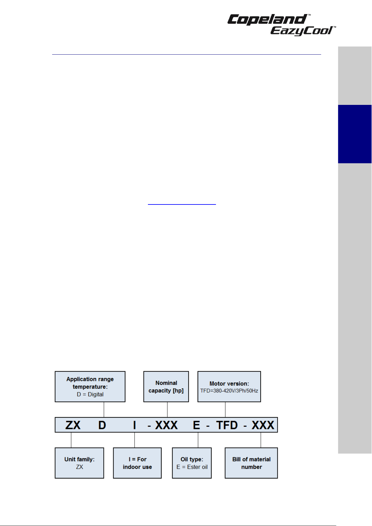
2.5 Nomenclature
The model designation contains the following technical information about the condensing unit:
Figure 1: Nomenclature ZXDI units
Safety
instructions
Product
description
Installation
Starting up &
operation
Maintenance &
repair
Certification &
approval
Dismantling &
disposal
Page 9
4 C6.1.10/0118-0318/E
2.6 Application range
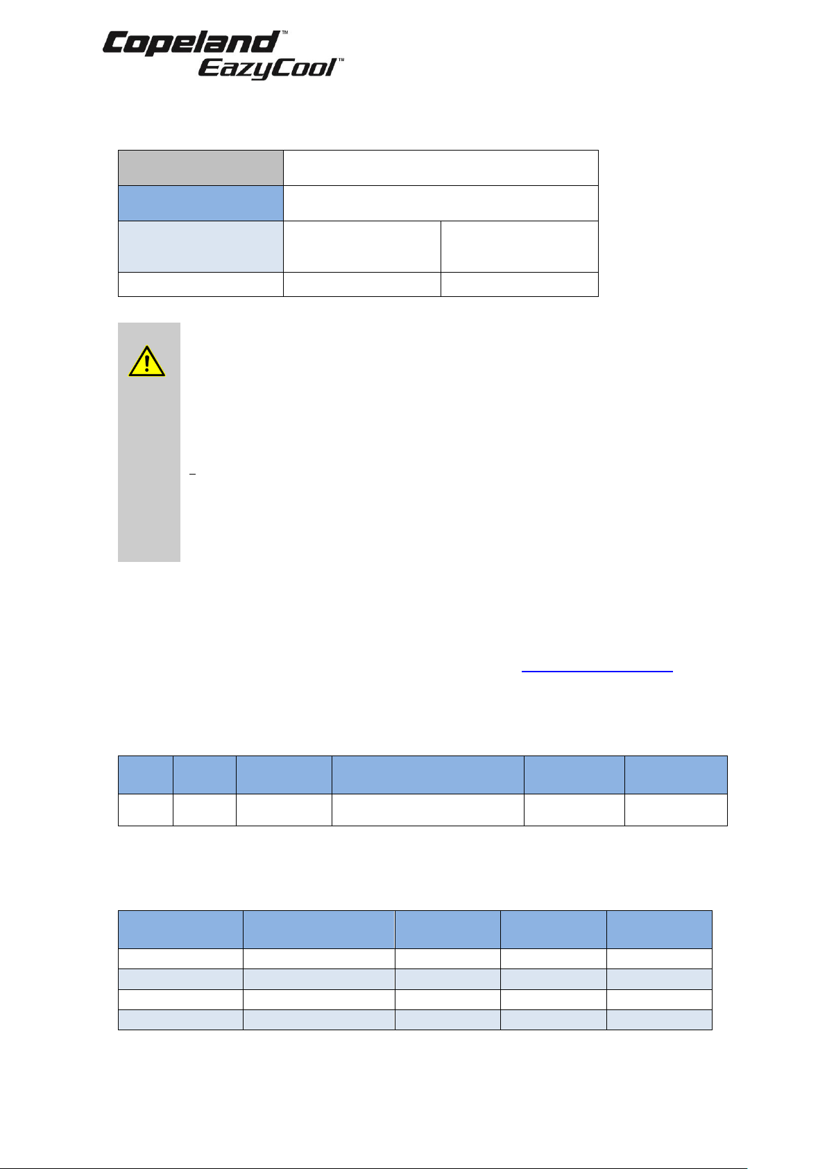
2.6.1 Qualified refrigerants and oils
Qualified refrigerants
R404A, R407A, R407F, R448A, R449A
R134a, R450A, R513A
Qualified
servicing oils
Emkarate RL 32 3MAF
Mobil EAL Arctic 22CC
Condensing
unit
ZXDI040E
ZXDI050E
ZXDI060E
ZXDI075E
Oil charge in litres
1.36
1.89
Table 1: Qualified refrigerants and oils
WARNING
Use of R450A and R513A refrigerants! Risk of compressor damage!
Migration of R450A or R513A into the compressor crankcase could cause low
oil viscosity, which could lead to compressor damage. When using R450A or
R513A it is critical to meet the following requirements:
▪ maintain adequate superheat settings with a minimum superheat of 8-10K;
▪ no liquid refrigerant migration into the compressor at any time, especially
during standstill, during or after defrost, or after reverse mode for example
in heat pumps;
▪ pump-down is not recommended;
▪ the use of a crankcase heater is mandatory;
▪ retrofit to R450A and R513A is only allowed for compressors which are
approved for these refrigerants.
Contact your local Application Engineering representative for any further
information.
NOTE: The ZXDI units are equipped with an oil separator. This separator is pre-charged
with 0.5 liter of oil.
2.6.2 Application limits
For application envelopes, please refer to the compressor application envelopes which can be
found in Copeland™ brand products Select software, available at www.emersonclimate.eu.
ZXDI indoor condensing units can be used at an ambient temperature from -15°C to 45°C. For
lower ambient temperatures please contact your local Application Engineering representative.
2.7 Bill of material
BOM
Family
Introduction
date
Controller concept
Oil
separator
Suction
accumulator
554
ZXDI
Jan/2018
XCM25D (Emerson - Dixell)
Yes
No
Table 2: BOM
2.8 Main components description
2.8.1 Compressor
Condensing
unit
Compressor model
(Digital)
Compressor
LRA (A)
Compressor
MOC* (A)
Unit rated
current (A)
ZXDI040E
ZBD29KQE-TFD
48
7.9
11.3
ZXDI050E
ZBD38KQE-TFD
64
11.3
14.7
ZXDI060E
ZBD45KQE-TFD
74
11.4
14.8
ZXDI075E
ZBD48KQE-TFD
100
14
17.4
* MOC = Maximum Operating Current
Table 3: Cross reference table units/compressor models
Page 10
C6.1.10/0118-0318/E 5
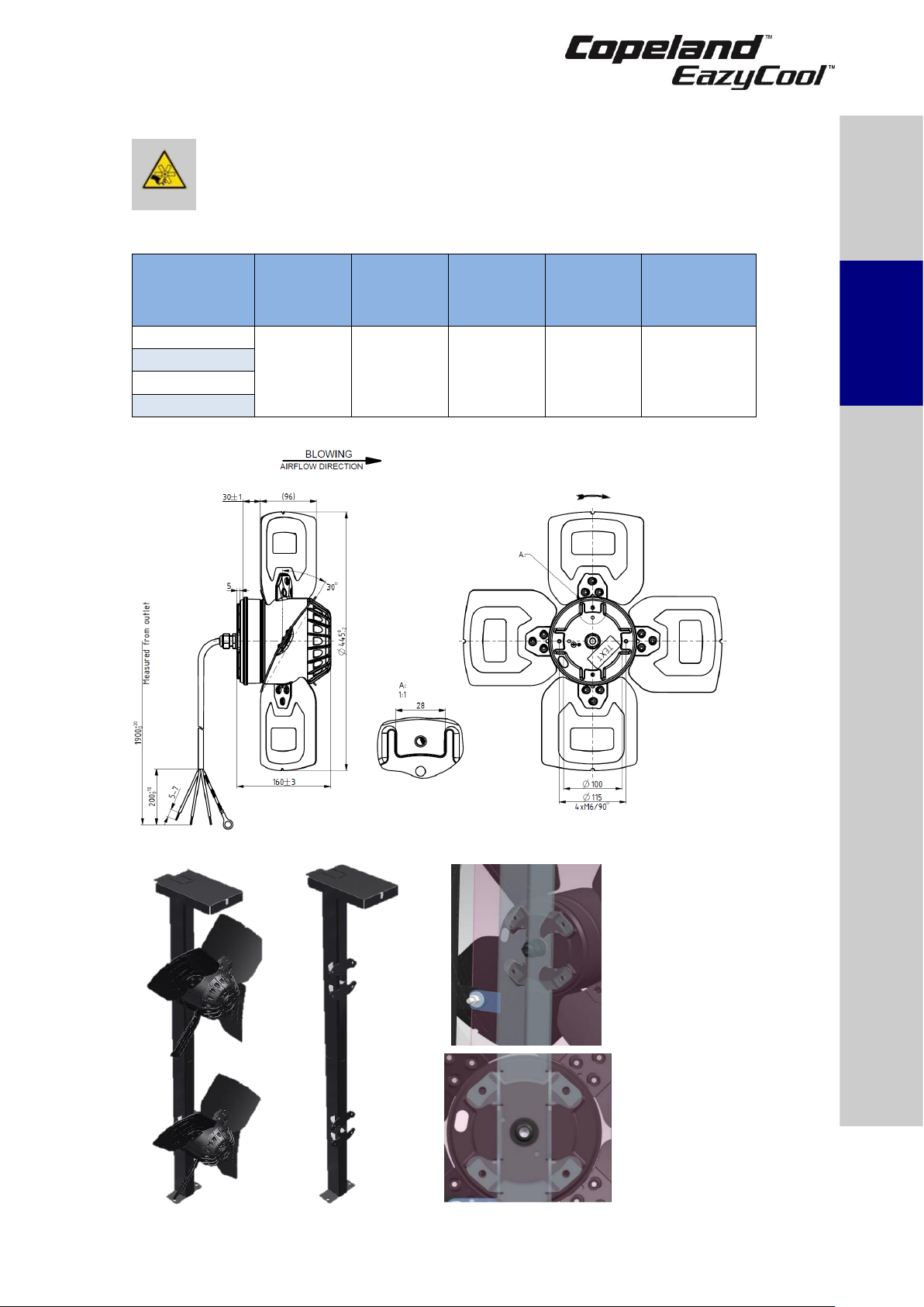
2.8.2 Condenser fan(s)
WARNING
Uncovered rotating parts! No safety grids on the condenser fans!
Personal injuries! Never start the condensing unit or run the fans with no air
ducts connected or without protective end-grids on the air outlets.
The condensers of the ZXDI condensing units are equipped with single-phase fans.
Condensing
unit
Nr. of fans
(pcs)
Fan blade
diameter
(mm)
Weight
per 1 fan
(kg)
Maximum
current @
100% per
1 fan (A)
Power
consumption
@ 100% per
1 fan (W)
ZXDI040E
2
450
~12
1.7
375
ZXDI050E
ZXDI060E
ZXDI075E
Table 4: Condenser fan technical data
Figure 2: Fan details and dimensions
Figure 3: Fan bracket details
Safety
instructions
Product
description
Installation
Starting up &
operation
Maintenance &
repair
Certification &
approval
Dismantling &
disposal
Page 11
6 C6.1.10/0118-0318/E
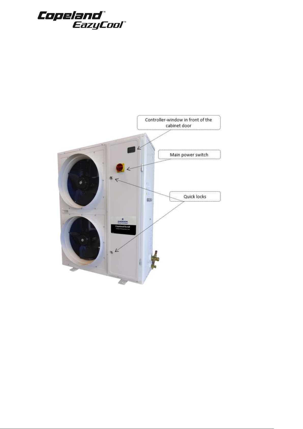
2.8.3 Housing
Copeland EazyCool ZXDI indoor condensing units have the following housing features:
▪ Controller-window in front of the cabinet door. The window is IP54 and shows the current
value of the electronic controller.
▪ The main power switch is installed on the cabinet door and allows to de-energize the unit
without opening the door. To open the door the main power switch must be in off position.
▪ The quick-locks allow for easy and quick opening of the cabinet door by means of the
cabinet key.
▪ The cabinet key is delivered with the unit. It is attached to one of the piping connections by
means of a cable strap.
Figure 4: ZXDI unit housing
Page 12
C6.1.10/0118-0318/E 7
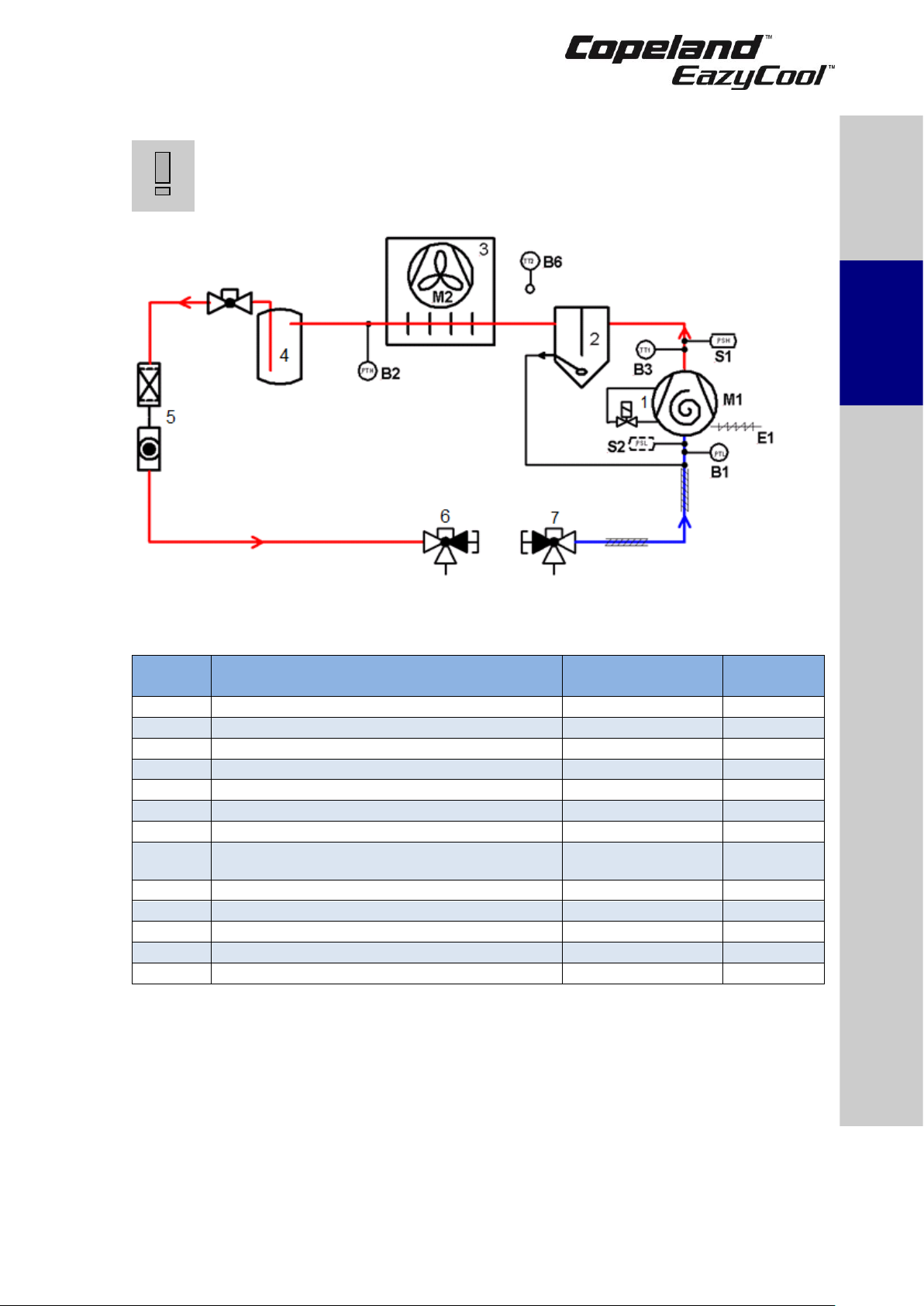
2.9 P&I diagram for ZXDI units
IMPORTANT
Check valve in front of liquid receiver! Risk of excessive internal
pressure caused by liquid expansion! Check required safety devices
according to EN 378.
Figure 5: P&I diagram for ZXDI units
Position
Description
Comments
Fast access
menu
1 (M1)
High efficient Copeland Scroll ZBD compressor
2
Oil separator
Pre-charged with 0.5 L
3 (M2)
Condenser with 2 fans
4
Liquid receiver with service valve
5
Filter drier / sight glass combination
6
Service valve, liquid line
7
Service valve, suction line
PSL (S2)
Adjustable low-pressure switch (not factory
mounted)
System safety
(option)
PSH (S1)
Non-adjustable high-pressure switch
System safety
PTL (B1)
Pressure sensor, low pressure
Compressor setpoint
P1P
PTH (B2)
Pressure sensor, high pressure
Fan speed control
P2P
TT1 (B3)
Discharge temperature sensor
Compressor safety
P3t
TT2 (B6)
Ambient temperature sensor
Additional functions
P6t
Table 5: Legend of the P&I diagram for ZXDI units
Safety
instructions
Product
description
Installation
Starting up &
operation
Maintenance &
repair
Certification &
approval
Dismantling &
disposal
Page 13
8 C6.1.10/0118-0318/E
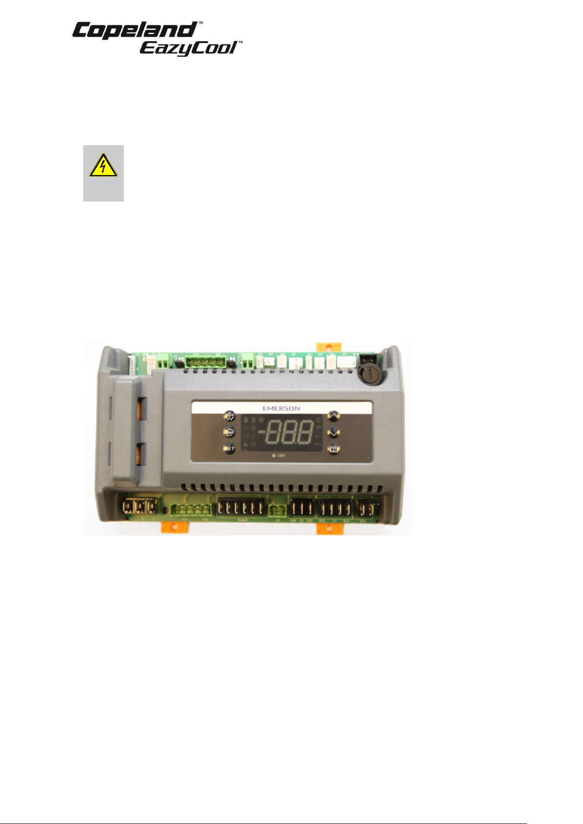
2.10 XCM25D Electronic controller – Features
The XCM25D controller is designed to be a powerful, flexible controller for use in multiple
applications. It has been developed for ZXDI condensing units and allows the adjustment of all
relevant parameters by the user.
2.10.1 Description
WARNING
Electrical shock hazard! Serious personal injuries! There are unused fast-
on pins (C1 & DO2) on the XCM25D which could be under voltage. They are
covered by insulated fast-on flags in the factory. Handle carefully when
removing insulating flags during service on site.
The controller is designed for usage in an indoor refrigeration unit. It is rated to be used for the
following environment:
▪ Outdoor controller ambient temperature for operation: -40C to 60C
▪ Ambient temperature for storage: -40C to 80C
▪ Maximum humidity: 90% at 48C (non-condensing)
▪ Board power: 24V AC +15%/-20%
▪ Voltage sensing capabilities - Three phase: 200-240, 380-460, 575V AC ± 10%
The units of measure are selectable. The factory default unit is [bar] (always considered relative)
for pressure and [°C] for temperature.
Figure 6: Electronic controller
2.10.2 Functionality
The controller allows for easy commissioning by the technician with the factory settings at the
highest program level. It also offers the possibility to make substantial changes to the system
optimization in further programming levels. Advanced functionality can also be activated.
The following functions are covered by the controller:
▪ Condensing unit control
▪ Condenser fan control
▪ Voltage and current sensing (compressor protection)
▪ Digital compressor control
NOTE: The XCM25D controller on ZXDI units includes all the functions necessary for unit
control. For additional functionalities please contact your local Application Engineering
representative.
Page 14
C6.1.10/0118-0318/E 9
Figure 7: XCM25D controller functionality overview
2.10.3 Main control & safety features
Suction pressure control: Each unit is equipped with a suction pressure transmitter. The
XCM25D controls the suction pressure by evaluating the input signal of the pressure transmitter.
When using a digital unit (ZXDI), the setpoint (C16/StC) and proportional band (C17/Pbd) need to
be adjusted. The signal of the suction pressure transmitter is also used for additional functionalities
and to keep the compressor running within the approved envelopes.
Condensing pressure control: Each unit is equipped with a high-pressure transmitter. The
XCM25D controls the condensing pressure by regulating the fan speed corresponding to the highpressure transmitter signal. The output signal of the unit controller to the fan speed controller is a
0-10V signal.
The unit controller can regulate the condensing pressure in two ways. The first approach is to keep
a constant condensing temperature. This mode is utilized by the factory settings. The pre-adjusted
setpoint is 27°C as a universal setting. If lower condensing pressure is required set up the
condenser setpoint (E39/FSP) to a lower value.
The second control way is fan modulation based on the compressor envelope. This mode of
setpoint control is only available if a suction pressure input is not used. The parameter (E38/FSM)
enables/disables the mode as needed. If this function is unused, the condensing temperature
setpoint will be set as a parameter (E39/FSP) value. The compressor is allowed to run at minimum
condensing temperatures based on the suction pressure of the compressor. This is the most
energy-efficient way to minimize the condensing temperature as much as possible.
NOTE: The fan speed controller is a Ziehl-Abegg PKE-6 controller. For more information
please refer to Chapter 2.20 "Fan speed control – Ziehl-Abegg PKE-6 controller" and to the
fan speed controller user’s guide – part of the unit standard delivery.
Maximal condenser fans pressure difference: To provide the condenser with appropriate air
flow the pressure drop for the fan must not exceed 60 Pa at 3500 m³/h per one fan. Additional
components such as mufflers, flaps, protection grids etc... must also be taken into account when
designing the air ducts route as they will cause additional pressure drop.
The following table shows pressure drops at 3500 m³/h for most commonly used ducting
components:
Spiral duct 500 mm
Ventilation bow 90°, 500 mm
1 Pa/m
10 Pa
Table 6
Example: If 8 meters spiral duct and 3 bows 90° are required on the installation, then
1 Pa × 8 + 10 Pa x 3 = 8 Pa + 30 Pa = 38 Pa, so 38 Pa < 60 Pa.
Compressor phase reversal: Ensures that the compressor keeps running in one direction only
(clockwise = right rotation) – necessary for a compliant Scroll compressor to compress and pump
refrigerant. Reset is automatic once the phase rotation is correct for the compressor.
Motor current overload protection: This feature eliminates the need for external current
protection for the compressor motor.
Condenser fan
control
Digital Scroll
control
Alarm
management
Electrical
protection
Monitoring of the discharge
line temperature
Safety
instructions
Product
description
Installation
Starting up &
operation
Maintenance &
repair
Certification &
approval
Dismantling &
disposal
Page 15
10 C6.1.10/0118-0318/E
Fixed high-pressure switches: This is a non-adjustable protection device designed to prevent
the compressor from operating outside of its safe high-pressure range. Reset is automatic for a
set number of trips (7) then the unit will lock out and require manual restart. This feature is
important to prevent the unit from cycling under these controls for a long period of time.
▪ Cut-out: 28.8 bar
▪ Cut-in: 24 bar
Adjustable high-pressure limitation: The unit controller provides the possibility to stop the unit
at a required discharge pressure which is lower than the cut-out value of the fixed high-pressure
switch. Detailed instructions can be found in chapter 2.10.4 "Additional features for customization"
hereunder.
Discharge temperature protection: Each unit is equipped with a discharge line sensor (NTC).
The XCM25D controller will stop the compressor if discharge temperatures reach unacceptable
levels.
Adjustable low-pressure alarm: The unit controller features an adjustable low-pressure alarm
managed by the suction pressure sensor. This alarm has been factory-set at 0.5 bar(rel), ie, the
lowest permitted pressure of the refrigerant with the lowest pressure-vapour properties. If needed
the user can modify this value according to the required application.
Option: Adjustable low-pressure switches PS1: This device protects the system against lowpressure operation. It must be adjusted depending on running conditions and potential special
requirements like pump-down. The compressor envelopes published in Select must be respected
at all times. In case of controller breakdown, the low-pressure switch could be used for emergency
operation (rewiring required).
A crankcase heater is directly connected to the controller. The crankcase heater will be energized
when the ambient sensor is below a given value (10°C) and the compressor has been off for a
period of time (5 minutes). The minimum off time does not apply at initial power-up.
In addition to the above, the ZXDI indoor condensing unit has the following features:
▪ Liquid line assembly (filter drier and sight glass/moisture indicator)
▪ Anti-corrosion treatment to the condenser fins
The electronic controller is also the base controller for the connection of many optional and
customer supplied functions such as:
▪ Main load controller
▪ Evaporator fan contactor
▪ Superheat controller for one electronic expansion device
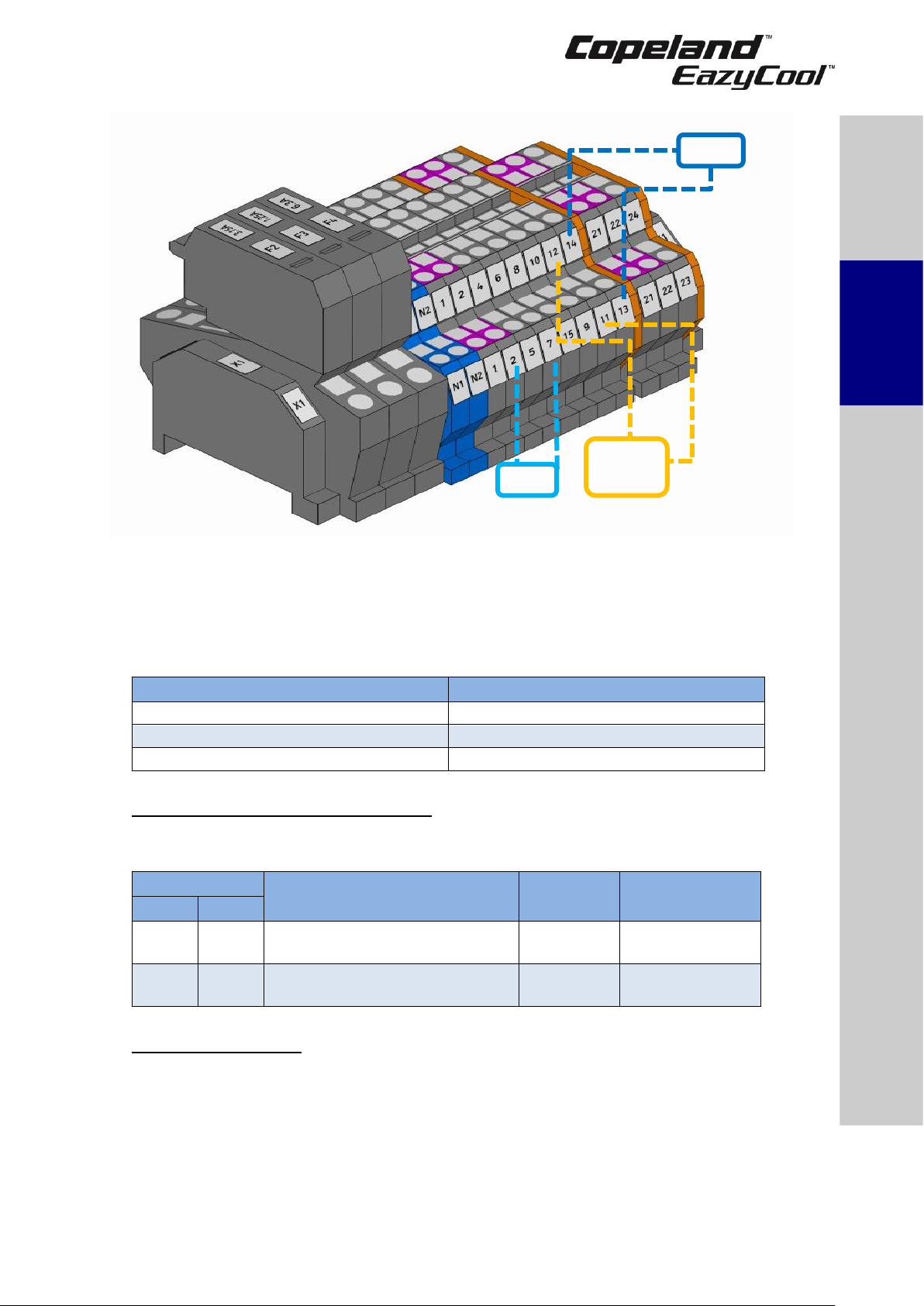
2.10.4 Additional features for customization
A lot of additional features are provided by the XCM25D controller. In the European design of the
electrical panel a few of the additional functionalities are prearranged and can easily be installed
by connecting additional hardware to the electrical terminals. The tables in Appendix 6 show the
parameters that have to be changed in case a special feature of the controller should be activated.
The tables do not show the required settings which have to be done by the system operator, eg,
choosing correct setpoints for different components and different applications.
NOTE: After programming an additional function, the system will have to be restarted. To
engage system restart, switch off the main power supply, wait for 5 seconds and switch it
on again.
Component
Description
Prearranged terminals /
Wiring diagram
B12
Low-pressure switch, optional; can be
ordered factory-installed.
Terminals: X1.2 / X1.7
Alarm contact
Sensor for evaporator or room
Terminals: X1.11 / X1.12
Sensor B7
Sensor for evaporator or room
(NTC10kΩ)
Terminals: X1.13 / X1.14
Table 7: Prearranged additional connections
Page 16
C6.1.10/0118-0318/E 11
Figure 8: Prearranged additional connections
NOTE: Depending on the required functionalities additional components might be
necessary. Please contact your local Application Engineering representative.
NOTE: Check the current limitations given by the controller relays.
NOTE: The solenoid valve function is not available on ZXDI indoor units.
Digital output
Specifications
DO1, DO2 and DO3
Relay SPDT 16A, 250V AC
DO3
Relay SPST 8A, 250V AC
DO4 and DO5
Relay SPST 5A, 250V AC
Table 8: Digital output specifications
Adjustable discharge pressure limitation
The controller has dedicated parameters to provide the possibility of adjustable discharge pressure
cut-out.
Parameters
Description
Factory
settings
Recommended
settings
ZXDE
ZXDI
E58
AU2
Condenser temperature/pressure
threshold for high alarm
27
Required value
E61
AH2
Condenser temperature/pressure
threshold for alarm recovery
23
Required value
Table 9: Discharge pressure limitations
Low ambient operation
Very low ambient temperatures can result in malfunction of expansion devices because of
insufficient pressure difference. Therefore, pressure cut-out during system start-up can occur. For
proper operation of the expansion devices, the unit running time must allow to build up sufficient
condensing pressure.
At low ambient conditions, the compressor will need to run for a minimum period of time to allow
the system pressures to stabilize. If the unit operates below a defined ambient temperature
(ambient temp. < C12/LAO) or if the ambient sensor has failed, the compressor should run for a
set period of time (C14/LAS) when it is started based on a low suction reading.
Safety
instructions
Product
description
Installation
Starting up &
operation
Maintenance &
repair
Certification &
approval
Dismantling &
disposal
Alarm
contact
Page 17
12 C6.1.10/0118-0318/E
The unit will be turned on for the minimum run time when the low-pressure input is closed.
If the pressure drops below the cut-out value or the low-pressure input opens, the unit should
continue to run for the remaining minimum on time (C14/LAS) or until a satisfactory condenser
pressure is reached (C13/LAd).
If a suction pressure transducer is present and the suction pressure falls below a given value
(C15/LAT) during the minimum on time (C14/LAS), then disregard the timer and shut the
compressor off to protect against vacuum operation.
NOTE: For additional features please contact your local Application Engineering
representative.
2.11 XCM25D Electronic controller – Programming
CAUTION
Low refrigerant charge! Compressor damage! Never energize the
unit/controller without minimum refrigerant system charge. There is a risk of
malfunction of the controller in deep vacuum operation which can cause
compressor damage.
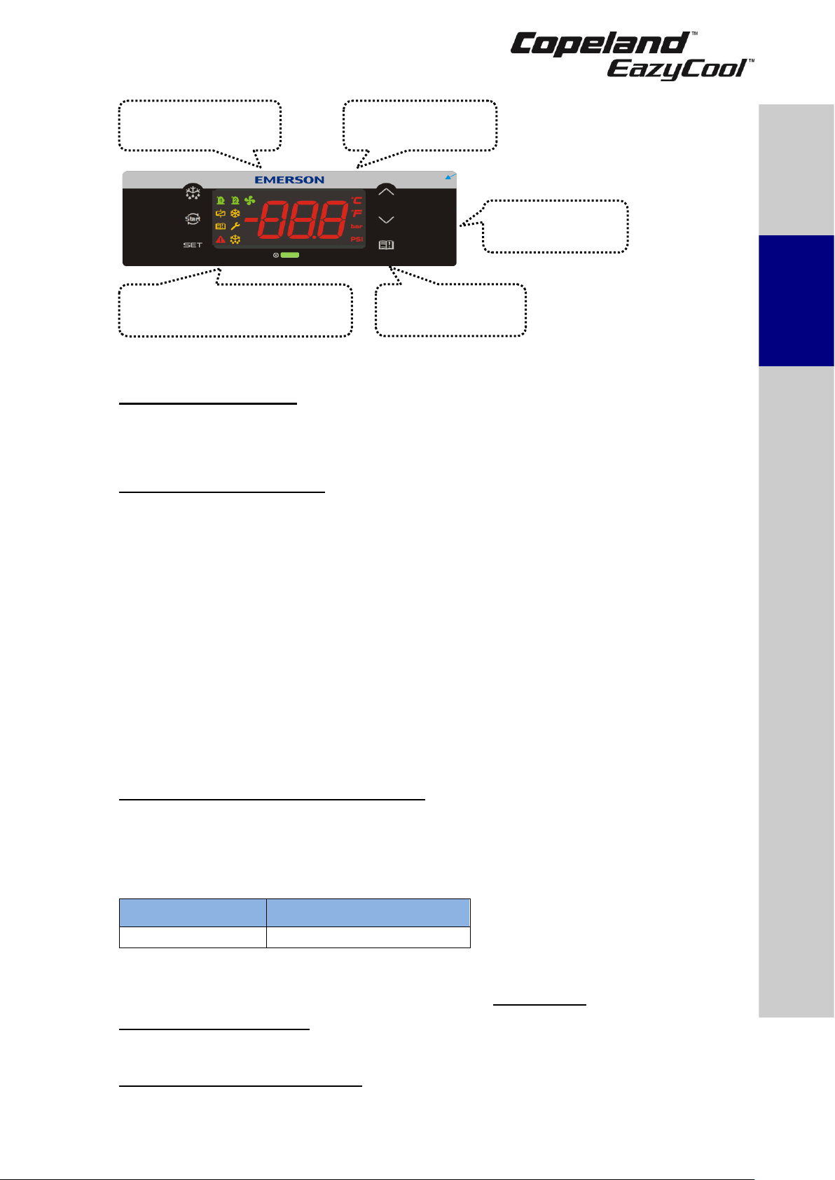
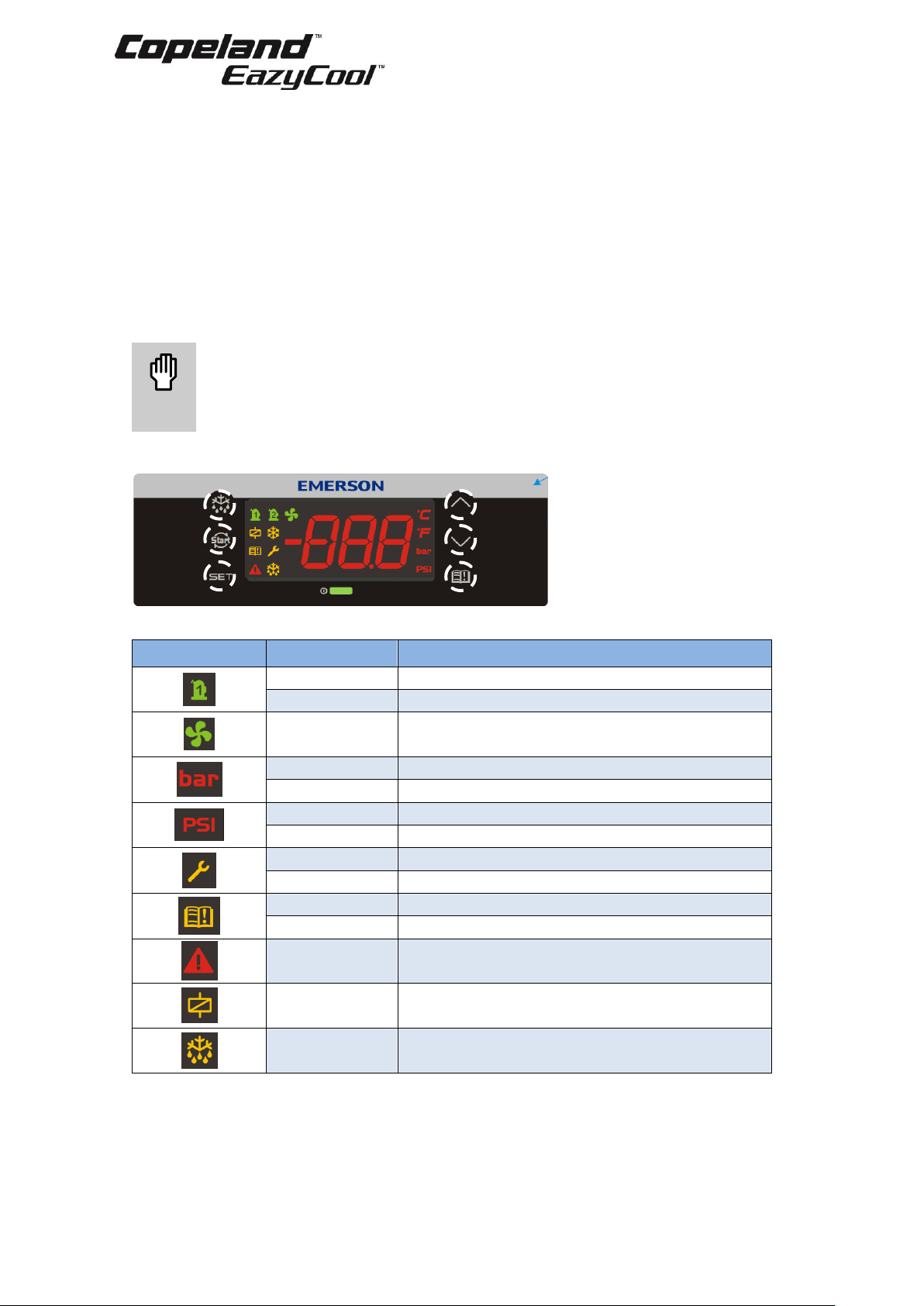
2.11.1 Programming the local display
Figure 9: Local display
LED
Mode
Function
On
Compressor 1 enabled
Flashing
Anti-short cycle delay enabled
On
Condensing fans enabled
On
Bar display
Flashing
Programming mode
On
PSI display
Flashing
Programming mode
On
When browsing the service menu
Flashing
In fast access menu
On
When browsing the alarm menu
Flashing
A new alarm occurred
On
An alarm is occurring
On
Digital unloader solenoid On
On
In defrost
Table 10: LED functions description
NOTE: By default, the local display will show the value of the suction pressure during
operation. This can be changed by choosing another value for parameter B03/Lod (Remote
Display visualization).
Page 18
C6.1.10/0118-0318/E 13
Setting for
B03/Lod
Value shown on the display
Comments
0
P1 value = Suction pressure
1
P2 value = Mid-coil temperature (condenser)
2
P3 value = Discharge line temperature
3
P4 value = Vapour inlet EVI
Not applicable
4
P5 value = Vapour outlet EVI
Not applicable
5
P6 value = Ambient temperature
6
P7 value = Not used in factory setting
7
PEr value = Probe error
8
Aou value = Analog output
Table 11: Display visualisation
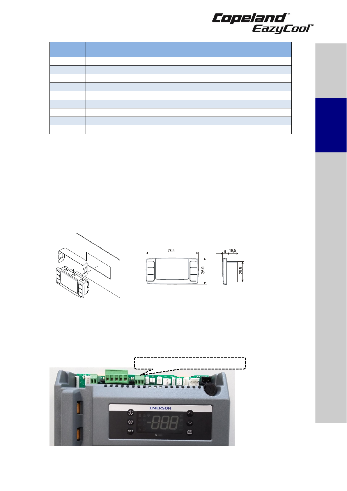
2.11.2 Remote display CCM60
The remote display CCM60 allows for remote monitoring and control of the XCM25D controller via
cable. This device has the same interface as the unit controller therefore the commands and
symbols are identical to those of the XCM25D controller. The remote display shall be mounted on
a vertical panel, in a 29 x 71 mm hole, and secured using the special bracket supplied (see
Figure 10).
The temperature range allowed for correct operation is 0°C to +60°C.
Avoid places subject to strong vibrations, corrosive gases, excessive dirt or humidity. Allow for air
to circulate through the cooling holes.
When front-mounted, the remote display is IP65 rated.
Figure 10: Remote display front panel mounting
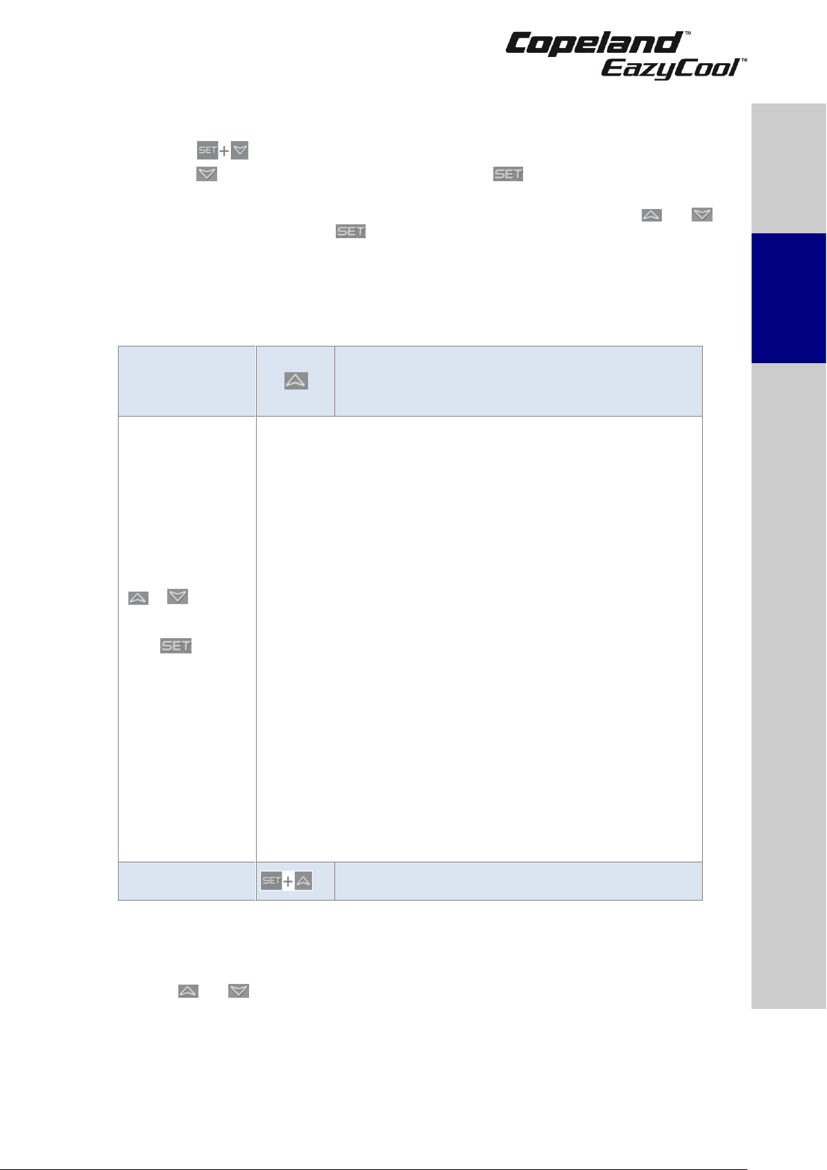
The remote display is a proprietary bus of communication for Dixell HMI (x-rep, CCM60) interfaces.
There are two connection terminals on the back of the remote display (+ and -).
NOTE: Emerson recommends using a shielded cable twisted pair 2 x 0.5mm².
The device must be connected to the VNR-terminal on the unit controller according to the polarity.
Figure 11 shows the VNR terminal on the unit controller.
Figure 11: VNR connection for the remote display
VNR connection for remote display
Safety
instructions
Product
description
Installation
Starting up &
operation
Maintenance &
repair
Certification &
approval
Dismantling &
disposal
Page 19

14 C6.1.10/0118-0318/E
Before connecting cables make sure the power supply complies with the hardware requirements.
Separate the terminal cables from the power supply cables, the outputs and the power
connections.
2.11.3 Single commands
Press the SET button to display the target setpoint. In programming mode, this
allows to select a parameter or to confirm an operation.
Press the RESET button and hold for 5 seconds to reset any lockouts if the
current state of the controller allows for it to be reset.
(UP) To view the fast access menu. In programming mode, this browses the
parameter codes or increases the displayed value.
(DOWN) In programming mode, this browses the parameter codes or decreases
the displayed value.
(SERVICE) To enter the service and alarm menu.
Hold for 3 seconds to start a manual defrost or terminate an active defrost.
Table 12: Single commands
2.11.4 Double commands – Entering programming level 1 "Pr1"
Press simultaneously for about 3 seconds to lock (PoF) or unlock (Pon) the
keyboard.
Press simultaneously to leave the programming mode or menu. On submenus
rtC and EEV this combination allows to go back to the previous level.
Press simultaneously for about 3 seconds to access the first level of
programming mode.
Table 13: Double commands
The device provides 2 programming levels:
▪ Pr1 with direct access
▪ Pr2 protected with a password (intended for experts)
2.11.5 How to program the parameters (Pr1 and Pr2)
Access pre-
program level
Press simultaneously for about 3 seconds to access the preprogramming level. The message rtC (real-time clock) appears.
Access
program level
or
Press the Up or Down key until the message Par appears.
Access Pr1
Press the SET button to enter the program level. First parameter
appears.
Select item
or
Select the parameter or submenu using the arrows.
Show value
Press the SET button.
Modify
or
Use the arrows to modify the value.
Confirm and
store
Press the SET button: the value will blink for 3 seconds, then the
display will show the next parameter.
EXIT
Press simultaneously to exit the programming mode, or wait
for 30 seconds (MTO) without pressing any key.
Table 14: Programming level 1 parameters
When entering the programming level for the first time the display will show the rtC (real-time
clock) label.
▪ Press to access parameters N01/02/03/04/05 (Min/Hr/MdY/Mon/YEr) to adjust time &
date. For further details, see Chapter 2.13, "Parameters level 1 – Required settings".
▪ Press or to change from the rtC label to the Par label, in order to access
programming level 1.
▪ Press : the parameters of programming level 1 can be changed.
Page 20
C6.1.10/0118-0318/E 15
2.11.6 Entering programming level 2 "Pr2"
To enter the Pr2 programming menu:
▪ Press simultaneously for 3 seconds. The first parameter label will be displayed.
▪ Press till the T18 label is displayed, then press the key;
▪ The blinking PaS label will be displayed; wait for a few seconds;
▪ The display will show "0 - -" with blinking 0: insert the password [321] using the and
keys and confirming with the key.
2.11.7 Fast access menu
This menu contains the list of probes and some values that are automatically evaluated by the
board such as the superheat and the percentage of valve opening. nP or noP stands for "probe
not present" or "value not evaluated", Err means "value out of range", "probe damaged, not
connected or incorrectly configured".
Entering fast access
menu
Press and release the UP arrow. The duration of the
menu in case of inactivity is 3 minutes.
The values that will be displayed depend on the
configuration of the board.
Use the
or
arrow to select
an entry, then
press
to see the value
or to go on with
another value.
▪ P1P: Pressure value of the P1 probe (suction pressure)
▪ P2t: Temperature value of the P2 probe (not valid)
▪ P2P: Pressure value of the P2 probe (discharge pressure)
▪ P3t: Temperature value of the P3 probe (discharge line
temperature)
▪ P4t: Temperature value of the P4 probe (not applicable)
▪ P5t: Temperature value of the P5 probe (not applicable)
▪ P6t: Temperature value of the P6 probe (ambient temperature)
▪ P7t: Temperature value of the P7 probe (free)
▪ SH: Value of superheat. nA = not available
▪ oPP: Percentage of step valve opening.
▪ SEtd: Value of the dynamic setpoint (condenser fan SET). This
information is available only if the dynamic setpoint function is
enabled.
▪ AOO: Percentage of the analog output (0-10V or TRIAC PWM
Mod.). This information is available only if the 0-10V or TRIAC PWM
Mod. is enabled.
▪ dStO: Percentage of the PWM output driving the valve of the Digital
Scroll compressor.
▪ L°t: Minimum room temperature.
▪ H°t: Maximum room temperature.
▪ HM: Menu.
▪ tU1: Voltage reading V1 (not valid in standard configuration)
▪ tU2: Voltage reading V2 (not valid in standard configuration)
▪ tU3: Voltage reading V3 (not valid in standard configuration)
▪ tA1: Current reading I1
▪ tA2: Current reading I2
Exit
Press simultaneously or wait for the timeout of about
60 seconds
Table 15: Fast access menu
2.12 Controller keyboard
2.12.1 How to lock the keyboard
Keep the and keys pressed simultaneously for more than 3 seconds. The "PoF" message
will be displayed and the keyboard will be locked. At this point it is only possible to see the setpoint
or the maximum or minimum temperatures stored. If a key is pressed for more than 3 seconds,
the "PoF" message will be displayed.
Safety
instructions
Product
description
Installation
Starting up &
operation
Maintenance &
repair
Certification &
approval
Dismantling &
disposal
Page 21
16 C6.1.10/0118-0318/E
2.12.2 How to unlock the keyboard
Keep the and keys pressed simultaneously for more than 3 seconds, till the "Pon"
message is displayed.
2.13 Parameters level 1 – Required settings
The XCM25D is preconfigured to reduce the required settings on job-site to a minimum. In most
cases it will not be necessary to enter programming level 2 "Pr2". Table 16 gives an overview of
the parameters available in programming level 1 "Pr1".
NOTE: When changing parameter C05 (LS) a reset of the controller (interruption of power
supply) is required.
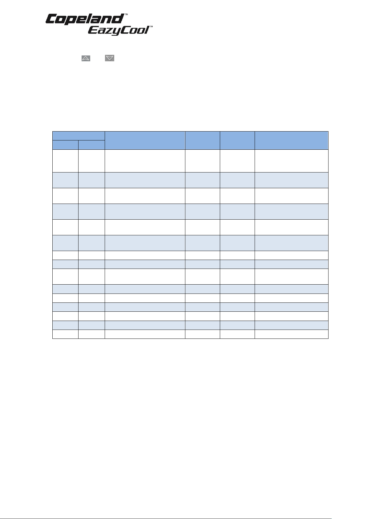
Parameters
Description
Unit
Factory
setting
Comments
ZXDE
ZXDI
C07
rEF
Refrigerant selection for
regulation
[-]
R404A
R134a, R404A, R407A,
R407F, R448A, R449A,
R450A, R513A
C16
StC
Digital compressor
setpoint
[bar]
3.3
C17
Pbd
Proportional band for
compressor regulation
[bar]
2.0
C21
tdG
Cycle time for digital
compressor
[sec]
10
C24
PMi
Minimum capacity for
digital compressor
[%]
20
C25
PMA
Maximum capacity for
digital compressor
[%]
100
D29
LPA
Low-pressure alarm value
[bar]
0.5
E39
FSP
Condenser setpoint
[°C]
35.0
E46
Fbd
Regulation band of
variable fan
[°C]
10.0
N01
Min
Current minute
[-]
[-]
N02
Hr
Current hour
[-]
[-]
N03
MdY
Day of the month
[-]
[-]
N04
Mon
Month
[-]
[-]
N05
YEr
Year
[-]
[-]
T18
PAS
Access to Pr2 level
[-]
[-]
Password: 3 2 1
Table 16: Parameters in programming level Pr1
NOTE: The full list of parameters in programming level "Pr2" can be found in Appendix 4.
2.14 Digital operation
A Digital unit is able to operate in a part-load mode. Part-load operation is achieved by loading
and unloading of the Digital scroll compressor for certain periods of time (time cycles). The cycle
of time can be chosen between 10 and 30 seconds. Example: if the time cycle is 20 seconds at
50% of capacity request, the compressor will run for 10 seconds loaded and 10 seconds unloaded.
The regulation starts when the suction pressure (AI1) increases and reaches the value
(SP-PB/2+(PB*PMI)/100) or (StC-Pbd/2+(Pbd*PMi)/100). Within the adjustment range
(SP-PB/2~SP+PB/2) or (StC-Pbd/2 ~ StC+Pbd/2) the Digital scroll compressor is activated in
PWM mode in accordance with the value of the control variable.
When the pressure is higher than (SP+PB/2) or (StC+Pbd/2) then the TRIAC output is at
maximum capacity. When the pressure is lower than (SP+PB/2) or (StC+Pbd/2) but higher than
(SP-PB/2) the Digital Scroll compressor modulates the capacity according to the proportional
band. If the pressure is lower than (SP-PB/2)/ (StC-Pbd/2) the Digital Scroll compressor switches
off.
Page 22

C6.1.10/0118-0318/E 17
For proper commissioning of the Digital unit the following diagram must be considered:
Figure 12: Digital operation
NOTE: When the digital valve on the compressor is discharged, the compressor is loaded.
NOTE: At start-up, the valve is energized for C20/Sut start-up time, ie, interval time with the
digital valve energized before regulation starts. It ranges from 0 to 10 seconds.
2.15 Reset to factory settings – Emerson "Hot Key"
2.15.1 How to save factory settings or user settings
There is no way to reset the XCM25D controller to factory settings other than with additional
equipment. Emerson recommends using the Emerson "Hot Key" (not part of the standard delivery)
to save the factory settings at initial power up. The same hot key can also be used to save user
settings.
Thanks to a special programming software (Emerson Wizmate) and corresponding hardware
(Emerson Prog-Tool), the user can:
▪ preprogram hot keys
▪ copy hot keys
▪ change parameter levels
▪ compare parameter lists
For further information please visit our website at www.emersonclimate.eu or contact your local
Application Engineering representative.
2.15.2 Emerson "Hot Key" for ZXDI units with XCM25D controller
The Emerson "Hot Key" DK00000300 can be used for uploading and downloading of parameter
lists. Copeland ident number 3226456.
Figure 13: Emerson "Hot Key"
Safety
instructions
Product
description
Installation
Starting up &
operation
Maintenance &
repair
Certification &
approval
Dismantling &
disposal
Page 23

18 C6.1.10/0118-0318/E
2.15.3 Location of the "Hot Key" plug connection on the XCM25D controller
The "Hot Key" plug connection is located on the upper left corner of the XCM25D.
Figure 14: Location of "Hot Key" plug connection
2.15.4 How to program a "Hot Key" from the controller (upload)
▪ Program one controller with the front keypad.
▪ When the controller is on, insert the "Hot Key" and press the UP key; the "uPL" message
appears followed a by a flashing "End" label.
▪ Press the SET key and the "End" label will stop flashing.
▪ Turn the controller off, remove the "Hot Key" and then turn it on again.
NOTE: The "Err" message appears in case of a failed programming operation. In this case
push the key again if you want to restart the upload or remove the "Hot Key" to abort the
operation.
2.15.5 How to program a controller using an Emerson "Hot Key" (download)
▪ Turn the controller off.
▪ Insert a pre-programmed "Hot Key" into the 5-pin receptacle and turn the controller on.
▪ The parameter list of the hot key will be automatically downloaded into the controller
memory. The "doL" message will blink followed a by a flashing "End" label.
▪ After 10 seconds the controller will restart working with the new parameters.
▪ Remove the "Hot Key".
NOTE: The message "Err" is displayed in case of a failed programming operation. In this
case turn the unit off, then on again if you want to restart the download, or remove the "Hot
Key" to abort the operation.
Page 24

C6.1.10/0118-0318/E 19
2.16 Troubleshooting – Alarm history
The controller records the total number of alarm activations (max 50) in the alarm menu (see
Appendix 5).
Action
Key or display
Notes
Enter menu
Push and release the ALR key.
Waiting for action
SEC
The menu to change the section will be entered. The
alarm list section is active.
Enter section list
Press SET to confirm. The following list will be
available to select the proper network function.
Select active alarm
code from list
or
Scroll the list of active alarms by alarm number (letter
+ number, A01-A50).
Press to see the alarm name or code.
Press to see the next active alarm.
Select the alarm to
see the detailed rtC
information
Enter the sub menu with alarm time details.
Select detailed
information from
active alarm list
or
With the rtC activated:
The Hur (hour) parameter is displayed.
Press to see the alarm hour.
Press : Min is displayed.
Press to see the alarm minute.
Press : dAy is displayed.
Press to see the alarm day.
Press : MOn is displayed.
Press to see the alarm month.
Press : YEA is displayed.
Press to see the alarm year.
Note: The clock info indicates the START time of the
alarm.
Without the rtC activated:
The COn (hours) parameter is displayed.
Press to see the compressor working hours.
To exit: press or wait for 15 seconds without
pressing any key.
Exit menu
Press simultaneously or wait for about 10
seconds without pressing any key.
Table 17: How to check the alarm list
2.17 Compressor motor protection
The electronic controller protects the compressor motor against the following:
▪ over current
▪ phase loss
▪ incorrect phase rotation
▪ voltage imbalance
If the compressor motor current exceeds a predefined (non-adjustable) current limit, the electronic
controller shuts the unit down and generates an error signal. For this function two of the main
phase supply lines to the compressor (compressor via the contactor) are routed through the
current sensors.
2.18 System pressure protection
2.18.1 High-pressure safety switch
A high-pressure switch is registered by the electronic board. The sensing device is a nonadjustable, high-pressure switch that will open in the event of an abnormally high discharge
pressure (cut-out 28.8 bar).
Safety
instructions
Product
description
Installation
Starting up
&
operation
Maintenance &
repair
Certification &
approval
Dismantling &
disposal
Page 25

20 C6.1.10/0118-0318/E
▪ The unit will stop then and restart automatically after a 5-minute delay and after unit
pressure has decreased to 24 bar.
▪ After 7 successive high-pressure cut-outs over 1 hour, the unit will lock out. In this case a
manual reset will be necessary.
2.18.2 High pressure: pressure relief valve
There is a connection port sideways on the top of the unit liquid receiver for a pressure relief valve.
A 3/8"-NPT connection is used. The pressure relief valve is not factory-assembled.
2.18.3 Low-pressure safety switch – Optional
In a way similar to the high-pressure sensor, the electronic controller registers the switching action
of the adjustable low-pressure switch, which will open in the event of an abnormally low suction
pressure:
▪ The unit will stop then restart automatically after a 3-minute delay and when the unit reaches
the cut-in pressure level.
The unit is always equipped with a suction pressure transmitter which also takes care for protection
against vacuum operation. The use of the optional low-pressure cut-out will provide the highest
protection level for the unit. In rare instances of controller breakdown, the optional low-pressure
switch would allow to run the unit in emergency mode.
2.18.4 Ambient temperature sensor
An ambient temperature sensor supplied by Emerson is connected to the electronic controller.
This temperature sensor has several functionalities like emergency mode control, lower fan speed
limitation and crankcase heater control. The sensor is located at the housing on the backside of
the compressor compartment.
2.19 Alarm output (DO5)
The digital output DO5 is pre-configured as an alarm contact. The relay (max. 5A, 250V AC) is
activated in case of alarms and lock-outs. Warnings will be shown only on the controller display.
2.20 Fan speed control – Ziehl-Abegg PKE-6 controller
The PKE-6 controller is used for continuous speed control adjustment on the variable voltage
motor of the fan. The electrical protection class of the controller is IP54.
The output signal of the unit controller XCM25D to the fan speed controller PKE-6 is a 0-10V digital
signal. It has two main functions: fan speed control and temperature/pressure control of the
condenser.
The fan speed factory setting is 100% rpm.
Depending on the characteristics of the connected air ducts, eg, presence of elbows, reductions,
grids, and the level of noise produced, the fan speed can be adjusted to an appropriate value
considering the expected unit performance and sound level.
A 10µF start capacitor is required for each fan.
Fan
speed
U
[V]
N
[rpm]
Pe
[W]
Airflow
[m3/h]
100%
230
1390
375
5352
98%
206
1360
373
5237
95%
190
1320
368
5083
87%
170
1210
361
4659
71%
150
985
332
3793
51%
130
709
257
2730
37%
110
514
178
1979
Table 18: Fan data based on changing frequency/fan speed
Page 26

C6.1.10/0118-0318/E 21
Figure 15: PKE-6 Fan speed controller details and dimensions
NOTE: For more information about the fan speed controller and possible adjustments,
please refer to the fan speed controller user’s guide – part of the unit standard delivery.
2.21 Dimensions in mm
The figures hereafter show the overall physical dimensions of the ZXDI indoor condensing units:
Figure 16: Dimensions of ZXDI condensing units (all models)
Safety
instructions
Product
description
Installation
Starting up &
operation
Maintenance &
repair
Certification &
approval
Dismantling &
disposal
Page 27

22 C6.1.10/0118-0318/E
3 Installation
WARNING
High pressure! Injury to skin and eyes possible! Be careful when opening
connections on a pressurized item.
Copeland EazyCool ZXDI indoor condensing units are delivered with a holding charge of neutral
gas.
The condensing unit should to be installed in a closed machine room. Soundproofing the machine
room is highly recommended because of a potentially high sound production. The room
characteristics must also be taken into account.
It is important to prevent any dirt, dust, plastic bags, leaves or papers from entering the air ducts
and covering or blocking the condenser and its fins. Proper protective end-grids should be used
for this purpose.
A clogged condenser will increase the condensing temperature, thus reducing the cooling
capacity, which could lead to a high-pressure switch tripping. Clean the condenser fins on a regular
basis.
The unit must be installed in such a way that the airflow through the connected air ducts is not
restricted. The incoming air flow must be sufficient to cover the entire air needs of the unit.
3.1 Condensing unit handling
3.1.1 Transport and storage
WARNING
Risk of collapse! Personal injuries! Move condensing unit only with
appropriate mechanical or handling equipment according to weight. Keep in
the upright position. Stack pallets on top of each other when not exceeding
300 kg. Do not stack single boxes on top of each other. Keep the packaging
dry at all times.
Figure 17: Transport and storage
3.1.2 Weights
Condensing
unit
Net weight*
(kg)
Gross weight**
(kg)
ZXDI040E
138
154
ZXDI050E
142
158
ZXDI060E
146
162
ZXDI075E
152
168
* Product without packaging
** Product including packaging
Table 19: Weights
Page 28

C6.1.10/0118-0318/E 23
3.2 Electrical connection
3.2.1 Power supply connections
Copeland EazyCool ZXDI indoor condensing units are designed for a 380-420V/3Ph/50 Hz power
supply. A voltage tolerance of ± 10% is acceptable.
The electrical connection of the condensing unit to the power supply must be made by qualified
technicians according to the valid electrical directives, for instance DIN EN 60204-1. The voltage
drop and the temperatures on line must also be considered for cable selection.
The circuit breaker must be switched off before opening the front door.
WARNING
Electrical shock hazard! Serious personal injuries! There are unused fast-
on pins (C1 & DO2) on the XCM25D which could be under voltage. They are
covered by insulated fast-on flags in the factory. Handle carefully when
removing insulating flags during service on site.
3.2.2 Maximum operating currents for cable selection
Condensing unit
Locked
rotor
Rated unit
current (A)*
ZXDI040E-TFD
48
11.3
ZXDI050E-TFD
64
14.7
ZXDI060E-TFD
74
14.8
ZXDI075E-TFD
100
17.4
* At nominal voltage of 400V
Table 20: Maximum operating currents for cable selection
3.2.3 Electrical wiring
Before commissioning, ensure that the neutral "N" and ground protection "PE" wires are connected
to the main switch.
3.2.4 Electrical protection standard (protection class)
▪ Units: IP class IPX4.
▪ Scroll compressors: IP21 according to IEC 34.
▪ Fan: IP44 according to IEC 34.
▪ Solenoid valve coils: IP65 according to DIN 43650.
3.2.5 Overload protection
WARNING
Isolating switch "On"! Danger of electric shock! Before any intervention on
the overload compressor protection, turn off the isolating switch to de-energize
the unit.
Figure 18
Safety
instruc
tions
Product
description
Installation
Starting up &
operation
Maintenance &
repair
Certification &
approval
Dismantling &
disposal
Page 29

24 C6.1.10/0118-0318/E
Condensing unit
Overload setting
Compressor MOC*
(A)
Overload range
(A)
ZXDI-040E-TFD
7.9
6 - 10
ZXDI-050E-TFD
11.3
9 - 14
ZXDI-060E-TFD
11.4
9 – 14
ZXDI-075E-TFD
14
13 – 18
* MOC = Maximum Operating Current
Table 21: Overload protection details
3.3 Refrigeration piping connections
3.3.1 Refrigeration piping installation
WARNING
High pressure! Risk of personal injury! The units are pressurized with dry
air. Be careful when opening connections on a pressurized item.
WARNING
Low surface temperature! Danger of frostbite! The liquid line should be
insulated with 19 mm insulation thickness. Temperature could be as low as
–15°C.
IMPORTANT
Tubing quality! Installation contamination! All interconnecting piping
should be of refrigeration grade, clean, dehydrated and must remain capped
at both ends until installation. Even during installation, if the system is left for
any reasonable period of time (say 2 hours), pipes should be re-capped to
prevent moisture and contaminant from entering the system.
Connection sizes! Unsuitable refrigerant flow rate! Do not assume that the
service connection sizes on the unit (at the service valves) are in fact the
correct size to run your interconnecting refrigeration pipes. The service valve
sizes have been selected for convenience of installation and in some cases
(larger units) these may be considered too small. However, for the very short
pipe run within our units these service connection sizes are adequate. All
interconnecting piping should be sized to satisfy the duty required.
The pipe should be sized to ensure optimum performance and good oil return. The sizing must
also take into account the full capacity range through which this particular unit will need to operate.
Pipe runs should be kept as short as possible, using the minimum number of directional changes.
Use large radius bends and avoid trapping of oil and refrigerant. This is particularly important for
the suction line. The suction line should ideally slope gently towards the unit. Recommendation
slope is 1/200 to 1/250. Upper and lower oil traps, double risers and reduced pipe diameters may
be required for suction lines where long vertical risers cannot be avoided.
All pipes should be adequately supported to prevent sagging which can create oil traps. The
recommended pipe clamp support distance is shown in Table 22 below:
Tube size
Max distance
between 2 clamp
supports
12.7 mm (1/2 inch)
1.20 m
16.0 mm (5/8 inch
1.50 m
22.0 mm (7/8 inch)
1.85 m
28.5 mm (1 1/8 inch)
2.20 m
Table 22: Maximum distance between 2 clamp supports
Page 30

C6.1.10/0118-0318/E 25
3.3.2 Brazing recommendations
IMPORTANT
Blockage! Compressor breakdown! Maintain a flow of oxygen-free nitrogen
through the system at very low pressure during brazing. Nitrogen displaces
the air and prevents the formation of copper oxides in the system. If allowed
to form, the copper oxide material can later be swept through the system and
block screens such as those protecting capillary tubes, thermal expansion
valves, and accumulator oil return holes.
Contamination or moisture! Bearing failure! Do not remove the plugs until
the compressor is set into the unit. This minimises any entry of contaminants
and moisture.
▪ Remove the discharge connection cap.
▪ Remove the suction connection cap.
▪ Open both valves mid-way. Care should be taken to avoid the holding charge releasing too
quickly.
▪ Be sure tube fitting inner surface and tube outer surface are clean prior to assembly.
▪ Both tubes are extended from the condensing unit housing, therefore we recommend to
isolate the housing by using a wet cloth on the copper tubing.
▪ Recommended brazing materials: a copper/phosphorous or copper/phosphorous/silver
alloy rod should be used for joining copper to copper whereas to join dissimilar or ferric
metals a silver alloy rod either flux coated or with a separate flux would be used.
▪ Use a double-tipped torch.
Figure 19: Brazing – Sectional view
3.3.3 Brazing procedure
For brazing of the tubes, please refer to Figure 20 and procedure hereunder:
▪ Fit the copper tube into the unit tube.
▪ Heat area 1. As the tube approaches brazing
temperature,
▪ Heat area 2 until braze temperature is attained.
It is necessary to heat the tube evenly. Move the torch
up and down and rotating around the tube.
▪ Add braze material to the joint while moving the
torch around the joint to flow braze material around the
circumference.
▪ Then heat area 3. This will draw the brazing material down into the joint.
NOTE: The time spent heating area 3 should be minimal. As with any brazed joint,
overheating may be detrimental to the final result.
Safety
instructions
Product
description
Installation
Starting up &
operation
Maintenance &
repair
Certificatio
n &
approval
Dismantling &
disposal
Figure 20: Suction tube brazing areas
Page 31

26 C6.1.10/0118-0318/E
To disconnect:
▪ Heat joint areas 2 and 3 slowly and uniformly until solder softens and tube can be pulled out
of the fitting.
To reconnect:
▪ See procedure above.
3.4 Location & fixings
IMPORTANT
Dust and dirt contamination! Risk of unit lifetime reduction! The unit
should always be installed in a location that ensures clean air flow. External
fouling of the condenser fins also leads to high condensing temperatures, and
will reduce the lifetime of the unit.
It is recommended that a clearance of 300 mm from the wall of the room (or the next unit) be
maintained from the unit left and rear panels whereas a clearance of 500 mm must be maintained
from the unit right, top and front panels (seen facing the front of the unit). Both service access and
airflow through connected air ducts have been considered in making these recommendations.
Where multiple units are to be installed in the same room, the installer has to consider each
individual case carefully. There can be many variations of unit quantities and available space and
it is not the intention of this manual to go over these. However, in general terms, air by-pass around
each condenser and between the units should be avoided at all times.
Ideally, the unit should be mounted level on a solid concrete slab with anti-vibration pads between
unit feet and concrete. However, the ZXDI unit has also been designed for wall mounting on
suitable brackets. In this case, it is equally important that the dimensional guidelines given in
Chapter 3.5 "Required distances" are followed. Wall mounting brackets are not part of the standard
delivery.
Another factor to consider in finding a good installation site is the direction of the prevailing wind.
For example, if the air leaving the condenser through the air ducts faces the prevailing wind, the
air flow through the condenser can be impeded, causing high condensing temperatures and
ultimately resulting in reducing the lifetime of the unit.
3.5 Required distances
Figure 21: Fixing dimensions and distances
Page 32

C6.1.10/0118-0318/E 27
3.6 Air ducts connection
WARNING
Uncovered rotating parts! No safety grids on the condenser fans!
Personal injuries! Never start the condensing unit or run the fans with no air
ducts connected or without protective end-grids on the air outlets.
The connection of the air ducts to the condensing unit has to be made based on standard rules
for air distribution ducts. Duct connection dimensions are designed based on standard EN 15062007, which has to be taken into consideration for all air ducts dimensioning.
The foil must be removed from the condenser fan before connecting the air ducts.
The condensing units covered in these guidelines are prepared for connection to air ducts with a
diameter of 500 mm.
Before commissioning and starting the unit, check the ducts for air leaks. Look for sections that
should be joined but might be separated and for possible holes in the air channels.
Two values must be taken into consideration when designing a proper air duct route and selecting
component parts, ie, the total pressure drop and the airflow.
The length of the air duct has little impact on the total pressure drop and on the air-flow (pressure
drop ~ approx. 0.5-1 Pa/m). An air duct length of up to 5 meters has virtually no impact at all on
pressure drop.
Elbows and other components such as diameter reductions on the air duct route have a much
bigger influence on total pressure drop and air flow – see Table 23 below.
Air duct diameter Ø 500 mm (connection to condenser per fan)
Total straight length (m)
1 2 3 4 5 6 7 8 9
10
11
12
13
14
15
Number of
elbows
1
2
3
4
5
6
Table 23: Maximum acceptable air duct length depending on diameter and number of elbows
When taking into account all the fittings, the total linear length and additional components, the total
pressure drop should be limited to 60 Pa per fan at 3500 m³/h. Please also refer to Chapter 2.10.3
"Main control & safety features".
Safety
instructions
Product
description
Installation
Starting up &
operation
Maintenance &
repair
Certification &
approval
Dismantling &
disposal
Page 33

28 C6.1.10/0118-0318/E
4 Starting up & operation
WARNING
Uncovered rotating parts! No safety grids on the condenser fans!
Personal injuries! Never start the condensing unit or run the fans with no air
ducts connected or without protective end-grids on the air outlets.
Before commissioning, ensure that all valves on the condensing unit are fully opened.
4.1 Evacuation
CAUTION
System pressure below atmospheric pressure! Compressor damage!
Never energize the unit/controller without minimum refrigerant system charge.
There is a risk of malfunction of the controller in deep vacuum operation which
can cause compressor damage.
IMPORTANT
The evacuation procedure is based upon achieving an actual system vacuum
standard and is NOT TIME DEPENDENT! The installation has to be
evacuated with a vacuum pump before commissioning. Proper evacuation
reduces residual moisture to 50 ppm. The installation of adequately sized
access valves at the furthest point from the compressor in the suction and
liquid lines is advisable. The system must be evacuated down to less than
3 mbar. If required break the vacuum with dry nitrogen. Pressure must be
measured using a vacuum pressure gauge on the access valves and not on
the vacuum pump. This serves to avoid incorrect measurements resulting from
the pressure gradient along the connecting lines to the pump.
4.2 Charging procedure
4.2.1 Refrigerant charging procedure
IMPORTANT
Inadequate charge! Overheating! The Scroll compressor design requires
system charging as quickly as possible with liquid refrigerant into the liquid
line. This will avoid running the compressor under conditions whereby
insufficient suction gas is available to cool not only the motor but also the
scrolls. Temperature builds up very quickly in the scrolls if this is not done.
Service valve closed! Compressor damage! Do not charge the unit with
vapour (gas). The suction service valve must not be fully closed at any time
when the compressor is running. To do so would cause damage to the
compressor in the same manner as explained above. This valve is provided
for ease of connection and for the fitting of service gauges without removing
the unit panel.
Pre-charging must be done with liquid refrigerant through the service valve on the liquid line. It is
advisable to pre-fill the suction side with a partial charge to avoid vacuum operation. Further
charging can be done by carefully filling refrigerant through the suction line while simultaneously
checking the sight glass.
NOTE: In order to meet the requirements of the Ecodesign Directive 2009/125/EC with
regard to efficient system operation, ensure the refrigerant charge is sufficient.
Page 34

C6.1.10/0118-0318/E 29
Figure 22: Service valves for refrigerant charging
An additional Schraeder connection is fitted on the liquid line
below the filter drier in the compressor chamber. It is also
possible to use this connection for charging or servicing.
Recommendation is to break vacuum in the system with partial
charge of refrigerant, then start the system.
For charge adjustment it is recommended to check the liquid
sight glass just before the expansion valve.
Figure 23: Liquid line service port
4.2.2 Oil charging procedure
Copeland EazyCool ZXDI indoor condensing units are pre-charged with oil. After commissioning,
the oil level should be checked and topped up if necessary.
NOTE: The oil level should be approximately halfway up the sight glass.
Emerson recommends charging with one of the following oil types:
▪ Emkarate RL 32 3MAF
▪ Mobil EAL Arctic 22 CC
Charging is done through the Schraeder valve located on the suction valve.
4.2.3 Oil separator
The ZXDI units are equipped with an oil separator. This separator is pre-charged with 0.5 liter of
oil.
4.3 Rotation direction of Scroll compressors
Scroll compressors, like several other types of compressors, will only compress in one rotational
direction. Three-phase compressors are protected against wrong rotation field by the unit
controller.
4.4 Maximum compressor cycle
Maximum permitted starts per hour: 10. The factory setting of the XCM25D system controller
already takes into account the maximum permitted starts and stops of the compressor. It also
controls the running time and the minimal downtime. It is recommended to change these settings
only in exceptional cases.
Service valves
Hexagone socket wrench
Valve covers
Schraeder valves
Safety
instructions
Product
description
Installation
Starting up &
operation
Maintenance &
repair
Certification &
approval
Dismantling &
disposal
Page 35

30 C6.1.10/0118-0318/E
4.5 Checks before starting & during operation
IMPORTANT
Liquid valves not fully opened! Liquid trap! Both valves should be fully
opened on the liquid line, in order to avoid trapping liquid.
▪ Check that all valves are fully opened.
▪ Set the essential parameters of the electronic controller in programming level 1 (refrigerant
type, compressor cut-out/cut-in settings, fan setpoint….) according to the required
application.
▪ Emerson recommends to check the oil level in the compressor after starting and operation
conditions have stabilised, and to add oil if needed to ensure a sufficient oil level (halfway
up the sight glass).
Page 36

C6.1.10/0118-0318/E 31
5 Maintenance & repair
5.1 Replacing a compressor
CAUTION
Inadequate lubrication! Bearing destruction! Exchange the accumulator
after replacing a compressor with a burned-out motor. The accumulator oil
return orifice or screen may be plugged with debris or may become plugged.
This will result in starvation of oil to the new compressor and a second failure.
In the case of a motor burnout, the majority of contaminated oil will be removed with the
compressor. The rest of the oil is cleaned through the use of suction and liquid line filter driers. A
100% activated alumina suction line filter drier is recommended but must be removed after
72 hours. It is highly recommended to replace the suction accumulator, if the system
contains one. This is because the accumulator oil return orifice or screen may be plugged with
debris or may become plugged shortly after a compressor failure. This will result in starvation of
oil to the replacement compressor and a second failure. When a compressor is exchanged in the
field, it is possible that a major portion of the oil may still be in the system. While this may not affect
the reliability of the replacement compressor, the extra oil will add to rotor drag and increase power
usage.
▪ De-energize the condensing unit before any intervention.
▪ Close valves to isolate the unit from the system.
▪ Recover the refrigerant from the unit and make sure that the compressor is not under
pressure.
▪ Release the compressor mounting parts then lift it to replace with a new compressor.
NOTE: For more detailed instructions, please refer to the compressor application
guidelines.
5.2 Condenser fins
CAUTION
Acid cleaning! Corrosion of condenser fins! Do not use acidic solutions to
clean the coil. After cleaning, the fins should be brushed lightly with a proper
fin comb.
NOTE: In order to meet the requirements of the Ecodesign Directive 2009/125/EC with
regard to efficient system operation, ensure the heat exchangers remain clean at all times.
Condenser fins become dirty over time as ambient air is induced to the condenser. Dirty coil
surfaces result in high condensing temperatures and poor unit performance. Regular cleaning is
recommended, the frequency of doing so being dependent on the installation and the surrounding
environment. As a general guide, it is advisable to do this at least once every two months.
As a general rule and for a clean environment we recommend the fins be cleaned with liquid
detergent diluted with clean water. The ZXDI condensing unit has a well-designed chassis with
falling levels towards a large drainage hole and provided the unit is installed level, any cleaning
solution should be able to drain away. A light brush downward (in the direction of the fins) should
be done before washing to remove heavy deposits.
5.3 Electrical connections
WARNING
Isolating switch "On"! Danger of electric shock! Before undertaking any
task on electrical equipment, turn off the main power supply to de-energise the
unit.
All condensing units will generate some degree of vibration. Copeland EazyCool ZXDI indoor
condensing units are no exception. However, the vibration level from the compliant scroll
technology is less severe than in units using reciprocating compressor technology. Thanks to this
reduced vibration, ZXDI units can be mounted on simple, less expensive rubber mounting pads.
Nevertheless, over time, due to these slight vibrations and to temperature fluctuations within the
unit housing, electrical terminations might become loose. The components most likely to be
Safety
instruction
s
Product
description
Installation
Starting up &
operation
Maintenance &
repair
Certification &
approval
Dismantling &
disposal
Page 37

32 C6.1.10/0118-0318/E
affected are the main terminal strip and the compressor contactor. It is suggested to check the
main electrical terminations for tightness and to carry out a visual inspection of the low voltage
crimped terminals at least once every 6 months.
5.4 Routine leak testing
NOTE: In order to meet the requirements of the Ecodesign Directive 2009/125/EC with
regard to efficient system operation, ensure the refrigerant and oil charges are sufficient.
All joints inside the system should be leak-tested as part of a regular maintenance schedule.
5.5 Condenser fans & motors
A yearly inspection of these items is recommended. Fastenings can become loose, bearings may
wear and fans may require cleaning of solid deposits that can cause rotational imbalance. Motors
come with lifelong lubrication bearings that do not require lubricating on a routine basis, but just
need to be checked for wear.
In case the fan(s) need(s) to be replaced or serviced, follow the steps below:
▪ De-energize the condensing unit before any intervention.
▪ Remove the top cover of the unit.
▪ Disconnect the air ducts from the fans in order to be able to access the unit front panel.
▪ Remove the entire front panel of the unit to access the condenser fans.
▪ Replace/service the fan(s).
6 Certification & approval
▪ Copeland EazyCool ZXDI indoor condensing units comply with the Low Voltage Directive
LVD 2014/35/EU. The applied harmonised standard is EN 60335-2-891 (Safety Household
and Similar Electrical Appliance, Part 2: Requirements for commercial refrigerating appliances
with an incorporated or remote refrigerant condensing unit or compressor).
▪ The piping complies with the Pressure Equipment Directive PED 2014/68/EU (Art.3 §3 -
Sound Engineering Practice).
▪ The condensing units and their components are CE marked as far as required and thereby
establish conformity with the relevant directives.
▪ Conformity Declarations for components are available as far as required.
▪ The Manufacturer's Declaration of Incorporation has to be respected when incorporating these
products into a machine.
7 Dismantling & disposal
Removing oil and refrigerant:
▪ Do not disperse in the environment.
▪ Use the correct equipment and method of removal.
▪ Dispose of oil and refrigerant according to national legislation and
regulations.
▪ Dispose of compressor and/or unit according to national legislation
and regulations.
Page 38

C6.1.10/0118-0318/E 33
DISCLAIMER
1. The contents of this publication are presented for informational purposes only and are not to
be construed as warranties or guarantees, express or implied, regarding the products or
services described herein or their use or applicability.
2. Emerson Climate Technologies GmbH and/or its affiliates (collectively "Emerson"), as
applicable, reserve the right to modify the design or specifications of such products at any time
without notice.
3. Emerson does not assume responsibility for the selection, use or maintenance of any product.
Responsibility for proper selection, use and maintenance of any Emerson product remains
solely with the purchaser or end user.
4. Emerson does not assume responsibility for possible typographic errors contained in this
publication.
Page 39

C6.1.10/0118-0318/E 34
Appendix 1: Overview of the ZXDI indoor unit components
Components
Digital
ZXDI
Compressor M1
Fan M2.1
Fan M2.2
Y1 Stepper valve EVI
[-]
Y3 Stepper valve liquid
[-]
Y2 DGS solenoid valve
E1 Crankcase heater
S3 Room thermostat (optional)
[-]
B1 Pressure transducer suction
B2 Pressure transducer discharge
B3 DLT NTC discharge
B4 EVI vapour in sensor NTC
[-]
B5 EVI vapour out sensor NTC
[-]
B6 Ambient temperature sensor NTC
B7 Temperature sensor (optional)
[-]
B11 High-pressure switch
B12 Low-pressure switch
[-]
Table 24: Overview of the ZXDI indoor unit components
Page 40

C6.1.10/0118-0318/E 35
Appendix 2: Wiring diagram – ZXDI units (380-420V/3Ph/50 Hz)
Figure 24: Wiring diagram – 3-Phase motor
Page 41

C6.1.10/0118-0318/E 36
Appendix 3: Parameter list level 1 (Pr1)
Legend
L1 = Parameter in Level 1 (without password)
L2 = Parameter in Level 2 (with password = 3 2 1)
N.V. = Parameter not accessible
NOTE: When changing parameter C05 (LS) a reset of the controller (interruption of power supply) is required.
Parameters
Description
Range
ZXDI
ZXDE
ZXDI
C07
rEF
Refrigerant selection for regulation
R404A (0-404) - R507 (1-507) R134a (2-134) - R22 (3-R22) R407C (4-07C) - R407A (5-07A) R407F (6-07F) – R448A (7-48A) R449A (8-49A) - R410A (9-410)
L1
C16
StC
Digital compressor setpoint
LS to US; C03 to C04
L1
C17
Pbd
Proportional band for compressor regulation
0.1 to 9.9 bar; 0.1 to 99.9 PSI;
1 to 999 KPA; 0.1°C to 25.5°C
L1
C21
tdG
Cycle time for digital compressor
10 to 40 sec
L1
C24
PMi
Minimum capacity for digital compressor
0 to PMA; 0 to C25
L1
C25
PMA
Maximum capacity for digital compressor
PMi to 100; C24 to 100
L1
D29
LPA
Low-pressure alarm value
0 to 15 bar
L1
E39
FSP
Condenser temperature setpoint when fan
setpoint modulation is disabled
-40°C to 110°C
L1
E46
Fbd
Regulation band of variable fan
0.1°C to 25.5°C
L1
N01
Min
Current minute
0 to 59
L1
N02
Hr
Current hour
0 to 23
L1
N03
MdY
Date of month
1 to 31
L1
N04
Mon
Month
1 to 12
L1
N05
YEr
Year
0 to 99
L1
T18
PAS
Access to Pr2 level
[0÷999]
L1
Table 25: Parameters level 1
Page 42

C6.1.10/0118-0318/E 37
Appendix 4: Parameter list Level 1 & Level 2 (Pr1 & Pr2)
Legend
L1 = Parameter in Level 1 (without password)
L2 = Parameter in Level 2 (with password = 3 2 1)
N.V. = Parameter not accessible
NOTE: When changing parameter C05 (LS) a reset of the controller (interruption of power supply) is required.
Parameters
Description
Range
Factory setting
ZXDI
ZXDE
ZXDI
A01
P1C
Probe P1 configuration
Not used (0-NU)
Suction pressure (0-5V)(1-SUP)
Suction pressure (05V)
L2
A02
P1i
Start of scaling for probe 1 (0-5V)
0-5V: -1.5 bar to P1E; -21 PSI to P1E
0
L2
A03
P1E
End of scaling for probe 1 (0-5V)
0-5V: P1i to 99.9 bar; P1i to 999 PSI
15
L2
A04
P1F
Probe P1 calibration
0-5V: -12.0 to 12.0 bar; -12.0 to12.0 PSI
0
L2
A05
P1d
Probe P1 reading error delay (P1C=0-5V)
0 to 255 min
5
L2
A06
P2C
Probe P2 configuration
Not used (0-NU)
Mid coil temperature (NTC10K)(1-MCT)
Mid coil pressure (0-5V)(2-MCP)
Mid-coil pressure (05V)
L2
A07
P2i
Start of scaling for probe 2
0-5V: -1.5 bar to P2E; -21 PSI to P2E
NTC10K: -40°C to P2E
0
L2
A08
P2E
End of scaling for probe 2
0-5V: P2i to 99.9 bar; P2i to 999 PSI
NTC10K: P2i to 110°C
35
L2
A09
P2F
Probe P2 calibration
0-5V: -12.0 to 12.0 bar; -12.0 to 12.0 PSI
NTC10K: -12°C to 12°C
0
L2
A10
P2d
Probe P2 reading error delay (P2C=0-5V)
0 to 255 min
0
L2
A11
P3C
Probe P3 configuration
Not used (0-NU)
Discharge line temperature (1-DLT)
Discharge line
temperature
L2
A12
P3F
Probe P3 calibration
-12°C to 12°C
0
L2
A13
P4C
Probe P4 configuration
Not used (0-NU)
Ambient temp (NTC10K)(1-AMT)
Thermostat temp (NTC10K)(2-TMT)
Vapour inlet temp (NTC10K)(3-UIT)
Vapour outlet temp (NTC10K)(4-UOT)
Evaporator temp (NTC10K)(5-EPT)
Liquid temp (NTC10K)(6-LLT)
Suction line temp (7-SLT)
Coil temp (8-COT)
Not used
L2
Page 43

C6.1.10/0118-0318/E 38
Parameters
Description
Range
Factory setting
ZXDI
ZXDE
ZXDI
A14
P4F
Probe P4 calibration
-12°C to 12°C
0
L2
A15
P5C
Probe P5 configuration
Not used (0-NU)
Ambient temp (NTC10K)(1-AMT)
Thermostat temp (NTC10K)(2-TMT)
Vapour inlet temp (NTC10K)(3-UIT)
Vapour outlet temp (NTC10K)(4-UOT)
Evaporator temp (NTC10K)(5-EPT)
Liquid temp (NTC10K)(6-LLT)
Suction line temp (7-SLT)
Coil temp (8-COT)
Not used
L2
A16
P5F
Probe P5 calibration
-12°C to 12°C
0
L2
A17
P6C
Probe P6 configuration
Not used (0-NU)
Ambient temp (NTC10K)(1-AMT)
Thermostat temp (NTC10K)(2-TMT)
Vapour inlet temp (NTC10K)(3-UIT)
Vapour outlet temp (NTC10K)(4-UOT)
Evaporator temp (NTC10K)(5-EPT)
Liquid temp (NTC10K)(6-LLT)
Suction line temp (7-SLT)
Coil temp (8-COT)
Ambient temp
(NTC10K)
L2
A18
P6F
Probe P6 calibration
-12°C to 12°C
0.0
L2
A19
P7C
Probe P7 configuration
Not used (0-NU)
Ambient temp (NTC10K)(1-AMT)
Thermostat temp (NTC10K)(2-TMT)
Vapour inlet temp (NTC10K)(3-UIT)
Vapour outlet temp (NTC10K)(4-UOT)
Evaporator temp (NTC10K)(5-EPT)
Liquid temp (NTC10K)(6-LLT)
Suction line temp (7-SLT)
Coil temp (8-COT)
Not used
L2
A20
P7F
Probe P7 calibration
-12°C to 12°C
0
L2
A21
dPE
Delay before activating probe error
0 to 255 sec
0
L2
B01
Unt
Measurement unit for pressure
Bar (0-BAR) – PSI (1-PSI) – KPA (2-TPA)
bar
L2
B02
CF
Measurement unit for temperature
°C (0-C)
°C
L2
Page 44

C6.1.10/0118-0318/E 39
Parameters
Description
Range
Factory setting
ZXDI
ZXDE
ZXDI
B03
Lod
Remote display visualization
P1 (0-P1) - P2 (1-P2) - P3 (2-P3) P4 (3-P4) - P5 (4-P5) - P6 (5-P6) P7 (6-P7) – Per (7-PER) – Aou (8-AOU)
P1
L2
B04
FiL
Filter enabling for probe reading
n (0-NO) - Y (1-YES)
YES
N.V.
B05
FiC
Coefficient for probe reading filter (0 = max,100 =
disable)
0 to 100, mEd (101)
50
N.V.
C03
Cin
Minimum setpoint for suction pressure/temperature
P1i to US; -50.0°C to US
0.6
L2
C04
CoU
Maximum setpoint for suction pressure/temperature
LS to P1E; LS to 60.0°C
7.2
L2
C05
LS
Compressor regulation probe selection
NU (0-NU)
Suction pressure probe (1-SUP)
Case temperature (2-CST)
Suction pressure switch (3-dIS)
Suction pressure probe
L2
C06
US
EXV closing time before compressor off
0 to 999 sec
0
L2
C07
CPb
Refrigerant selection for regulation
R404A (0-404) - R507 (1-507) R134a (2-134) - R22 (3-R22) –
R407C (4-07C) - R407A (5-07A) R407F (6-07F) – R448A (7-48A) R449A (8-49A) - R410A (9-410)
R404A
L1
C08
CoM
Setpoint offset
NU (0-NU)
Small offset (1-SOF)
Medium offset (2-MOF)
Large offset (3-LOF)
LAO (4-FOF)
Not used
L2
C09
rEF
Ambient temperature operation setpoint
-40°C to 110°C
-20
L2
C10
SPo
Pressure/Temperature operation for ambient
differential
0.0 to 9.9 bar; 0.0 PSI to 99.9 PSI
0.0°C to 25.5°C
1
L2
C11
LAI
Ambient temperature recover differential
0.1°C to 25.5°C
5
L2
C12
LAO
Ambient temperature threshold for low ambient
operation
-40°C to 110°C
-10
L2
C13
LAd
Temperature/Pressure to end low ambient timer and
resume normal operation
-40°C to 110°C
-1.5 to 99.9 bar; -21 to 999 PSI
10
L2
C14
LAS
Compressor minimum on time in low ambient
operation
0 to 255 sec
10
L2
C15
LAT
Pressure to end low ambient timer and shut off the
compressor
-1.5 to 99.9 bar; -21.0 to 999 PSI
0.5
L2
Page 45

C6.1.10/0118-0318/E 40
Parameters
Description
Range
Factory setting
ZXDI
ZXDE
ZXDI
C16
LMO
Digital compressor setpoint
LS to US
3.3
L1
C17
LAP
Proportional band for compressor regulation
0.1 to 9.9 bar; 0.1 to 99.9 PSI; 0.1°C to
25.5°C
2
L1
C18
StC
Band offset for compressor regulation
0 to 9.9 bar; 0 to 99.9 PSI; 0.0°C to 25.5°C
0
L2
C19
Pbd
Integral time
0 to 999 sec
250
L2
C20
rS
Start-up time: interval time with digital valve
energized before regulation starts
0.0 to 10.0 sec
10
L2
C21
inC
Cycle time for digital compressor
10 to 40 sec
20
L1
C22
SUt
Safety value for PI regulator (in case of probe error)
0 to 100%
50
L2
C23
tdG
Number of active compressor when probe error
0 (0) – 1 (1) – 2 (2)
0
L2
C24
SPi
Minimum capacity for digital compressor
0 to PMA
20
L1
C25
SPr
Maximum capacity for digital compressor
PMi to 100
100
L1
C26
PMi
Time with DGS at PMA before starting another load
0 to 255 sec
0
L2
C27
PMA
Time with DGS at PMi before switching off another
load
0 to 255 sec
0
L2
C28
ton
R404A Enable function
Disable (0-NO) - Enable (1-YES)
Enable
N.V.
C29
toF
R507 Enable function
Disable (0-NO) - Enable (1-YES)
Enable
N.V.
C30
Er0
R134a Enable function
Disable (0-NO) - Enable (1-YES)
Enable
N.V.
C31
Er1
R22 Enable function
Disable (0-NO) - Enable (1-YES)
Enable
N.V.
C32
Er2
R407C Enable function
Disable (0-NO) - Enable (1-YES)
Enable
N.V.
C33
Er3
R407A Enable function
Disable (0-NO) - Enable (1-YES)
Enable
N.V.
C34
Er4
R407F Enable function
Disable (0-NO) - Enable (1-YES)
Enable
N.V.
C35
Er5
R448A Enable function
Disable (0-NO) - Enable (1-YES)
Enable
N.V.
C36
Er6
R449A Enable function
Disable (0-NO) - Enable (1-YES)
Enable
N.V.
C37
Er7
R410A Enable function
Disable (0-NO) - Enable (1-YES)
Disable
N.V.
C38
Er8
Compressor regulation control signal
Pressure (0-PRS) - temperature (1-TMP)
Pressure
L2
D01
Er9
Output delay at start-up
0 to 255 sec
5
L2
D02
dEU
Compressor On time with faulty probe
0 to 255 min
0
L2
D03
odS
Compressor Off time with faulty probe
0 to 255 min
0
L2
D04
Con
Minimum time between two starts (same compressor)
0 to 15 min
4
L2
Page 46

C6.1.10/0118-0318/E 41
Parameters
Description
Range
Factory setting
ZXDI
ZXDE
ZXDI
D05
CoF
Delay between compressor switch-off and start-up
(same compressor)
1 to 900 sec
120
L2
D06
2on
Delay between two different loads start-up
[0÷99.5] min, resolution 10 sec
10
N.V.
D07
2oF
Delay between two different loads switch-off
[0÷99.5] min, resolution 10 sec
10
N.V.
D08
don
Minimum time a stage stays switched on
[0÷99.5] min, resolution 10 sec
0
L2
D09
doF
Maximum time a stage stays switched on
[0.00÷24.00] hours, resolution 10 min
0:00
L2
D10
dnF
don delay enabled also for the first request
No (0-NO) - Yes (1-YES)
NO
L2
D11
MAo
doF delay enable also for the first switching off
No (0-NO) - Yes (1-YES)
NO
L2
D12
dn1
Low suction pressure alarm delay
0 to 999 sec
0
L2
D13
dF1
Low suction pressure error signal enabling
No (0-NO) - Yes (1-YES)
YES
L2
D14
LPd
Compressor minimum off time for high-pressure
switch protection
0 to 15 min
5
L2
D15
LPE
Number of high-pressure switch activations before
compressor lock
0 to 15
7
L2
D16
HPF
Bump start enable
No (0-NO) - Yes (1-YES)
NO
N.V.
D17
HPn
Bump start ambient threshold
-40°C to 110°C
0
N.V.
D18
bMP
Compressor stop time for next bump start
0 to 23 hours and 50 minutes
1:00
N.V.
D19
bMA
Compressor on time during bump function
1 to 15 sec
2
N.V.
D20
bMi
Compressor off time during bump function
1 to 15 sec
15
N.V.
D21
bon
Number of cycles during bump start
1 to 15
3
N.V.
D22
boF
DLT alarm temperature to stop compressor
-40°C to 180°C
140
L2
D23
bMn
DLT alarm recover temperature to turn on
compressor
-40°C to 180°C
90
L2
D24
dLt
DLT alarm activation delay
0 to 255 sec
30
L2
D25
dLr
Compressor minimum off time for DLT Alarm
0 to 255 min
5
L2
D26
dLd
Number of DLT alarm activations before compressor
lock
0 to 15
10
L2
D27
dCt
Time to ignore low DLT sensor error at start-up
0 to 255 min
5
L2
D28
dLn
Compressor minimum off time for low-pressure
switch protection
0 to 15 min
3
L2
D29
dLi
Low-pressure alarm value
0 to 15 bar
0.5
L1
Page 47

C6.1.10/0118-0318/E 42
Parameters
Description
Range
Factory setting
ZXDI
ZXDE
ZXDI
D30
LPF
Cold start enable
Disable (0) - Enable (1)
Disable
N.V.
D31
LPA
DLT temperature threshold to trip during cold start
-40 to 180°C
60
N.V.
D32
CSb
Suction pressure threshold to trip during cold start
-1.5 to 99.9 bar
0.5
N.V.
D33
CdL
Allowed number of cycles of DLT temperature trips
during cold start
1 to 15
4
N.V.
D34
CSL
Allowed number of cycles of low pressure trips during
cold start
1 to 15
4
N.V.
D35
Cdt
Compressor stop time during cold start
1 to 999 sec
180
N.V.
E01
CSt
Condenser fan motor modulation type
Not used (0-NU)
Fan cycling (1-CYC)
Modulated fan (2-MOD)
Modulated fan
L2
E02
CCs
Low setpoint for condenser fan map 1 (for R404A,
R507)
-40°C to HT1
10
N.V.
E03
FCM
Lower suction pressure point for condenser fan map
1 (for R404A, R507)
-1.5 bar to HP1; -21 PSI to HP1
3.3
N.V.
E04
LT1
High setpoint for condenser fan map 1 (for R404)
LT1 to 110°C
30
N.V.
E05
LP1
High suction pressure point for condenser fan map 1
(for R404A, R507)
LP1 to 99.9 bar; LP1 to 999 PSI
7.2
N.V.
E06
HT1
Low setpoint for condenser fan map 2 (for R134)
-40°C to HT2
25
N.V.
E07
HP1
Lower suction pressure point for condenser fan map
2 (for R404)
-1.5 bar to HP2; -21 PSI to HP2
2.5
N.V.
E08
LT2
High setpoint for condenser fan map 2 (for R134)
LT2 to 110°C
40
N.V.
E09
LP2
High suction pressure point for condenser fan map 2
(for R404)
LP2 to 99.9 bar; LP2 to 999 PSI
3.9
N.V.
E10
HT2
Low setpoint for condenser fan map 3 (for R22)
-40°C to HT3
20
N.V.
E11
HP2
Low suction pressure point for condenser fan map 3
(for R22)
-1.5 bar to HP3; -21PSI to HP3
5.2
N.V.
E12
LT3
High setpoint for condenser fan map 3 (for R22)
LT3 to 110°C
30
N.V.
E13
LP3
High suction pressure point for condenser fan map 3
(for R22)
LP3 to 99.9 bar; LP3 to 999 PSI
6.4
N.V.
E14
HT3
Low setpoint for condenser fan map 4 (for R407C)
-40°C to HT4
10
N.V.
E15
HP3
Lower suction pressure point for condenser fan map
4 (for R404)
-1.5 bar to HP4; -21 PSI to HP4
1.3
N.V.
Page 48

C6.1.10/0118-0318/E 43
Parameters
Description
Range
Factory setting
ZXDI
ZXDE
ZXDI
E16
LT4
High setpoint for condenser fan map 4 (for R407C)
LT4 to 110°C
38
N.V.
E17
LP4
High suction pressure point for condenser fan map 4
(for R404)
LP4 to 99.9 bar; LP4 to 999 PSI
5.4
N.V.
E18
HT4
Low setpoint for condenser fan map 5 (for R407A)
-40°C to HT5
10
N.V.
E19
HP4
Low suction pressure point for condenser fan map 5
(for R407A)
-1.5 bar to HP5; -21 PSI to HP5
2.5
N.V.
E20
LT5
High setpoint for condenser fan map 5 (for R407A)
LT5 to 110°C
27
N.V.
E21
LP5
High suction pressure point for condenser fan map 5
(for R407A)
LP5 to 99.9 bar; LP5 to 999 PSI
5.3
N.V.
E22
HT5
Low setpoint for condenser fan map 6 (for R407F)
-40°C to HT6
10
N.V.
E23
HP5
Low suction pressure point for condenser fan map 6
(for R407F)
-1.5 bar to HP6; -21 PSI to HP6
1.7
N.V.
E24
LT6
High setpoint for condenser fan map 6 (for R407F)
LT6 to 110°C
38
N.V.
E25
LP6
High suction pressure point for condenser fan map 6
(for R407F)
LP6 to 99.9 bar; LP6 to 999 PSI
6.3
N.V.
E26
HT6
Low setpoint for condenser fan map 7 (for R448A)
-40°C to HT7
10
N.V.
E27
HP6
Low suction pressure point for condenser fan map 7
(for R448A)
-1.5 bar to HP7; -21 PSI to HP7
3.3
N.V.
E28
LT7
High setpoint for condenser fan map 7 (for R448A)
LT7 to 110°C
30
N.V.
E29
LP7
High suction pressure point for condenser fan map 7
(for R448A)
LP7 to 99.9 bar; LP7 to 999 PSI
7.2
N.V.
E30
HT7
Low setpoint for condenser fan map 8 (for R449A)
-40°C to HT8
10
N.V.
E31
HP7
Low suction pressure point for condenser fan map 8
(for R449A)
-1.5 bar to HP8; -21 PSI to HP8
3.3
N.V.
E32
LT8
High setpoint for condenser fan map 8 (for R449A)
LT8 to 110°C
30
N.V.
E33
LP8
High suction pressure point for condenser fan map 8
(for R449A)
LP8 to 99.9 bar; LP8 to 999 PSI
7.2
N.V.
E34
HT8
Low setpoint for condenser fan map 9 (for R410A)
-40°C to HT9
10
N.V.
E35
HP8
Low suction pressure point for condenser fan map 9
(for R410A)
-1.5 bar to HP9; -21 PSI to HP9
3.3
N.V.
E36
LT9
High setpoint for condenser fan map 9 (for R410A)
LT9 to 110°C
30
N.V.
E37
LP9
High suction pressure point for condenser fan map 9
(for R410A)
LP9 to 99.9 bar; LP9 to 999 PSI
7.2
N.V.
Page 49

C6.1.10/0118-0318/E 44
Parameters
Description
Range
Factory setting
ZXDI
ZXDE
ZXDI
E38
HT9
Fan setpoint modulation enabling
No (0-NO) - Yes (1-YES)
NO
L2
E39
HP9
Condenser temperature setpoint when fan setpoint
modulation is disabled
-40°C to 110°C
27
L1
E40
FSM
Minimum condenser temperature setpoint
-40°C to 110°C
10
L2
E41
FSP
High ambient fan motor override enabled
No (0-NO) - Yes (1-YES)
YES
L2
E42
MCS
High ambient fan motor override differential
0.1°C to 25.5°C
5
L2
E43
FAE
High DLT fan motor override enabled
No (0-NO) - Yes (1-YES)
YES
L2
E44
FAd
High DLT fan motor override differential
-40°C to 180°C
120
L2
E45
FdE
Minimum fan motor speed
0 to 100%
40
N.V.
E46
FdS
Regulation band of variable fan
0.1°C to 25.5°C
10
L1
E47
MSF
Integration time for fan
0 to 999 sec
500
L2
E48
Fbd
Fan full speed duration at fan start-up
0 to 255 sec
0
L2
E49
inF
Fan minimum on time
0 to 255 sec
5
L2
E50
FFS
Fan minimum off time
0 to 255 sec
10
L2
E51
FCn
Fixed condenser fan setpoint
-40°C to 110°C
23
L2
E52
FCF
Fan 1 differential
0.1°C to 25.5°C
7
L2
E53
SF1
Fan 1 to fan 2 differential
0.1°C to 25.5°C
10
L2
E54
HF1
Fan 2 differential
0.1°C to 25.5°C
7
L2
E55
SFD
Fan control with ambient sensor - Min ambient
-40°C to E56
0
L2
E56
HF2
Fan control with ambient sensor - Max ambient
E55 to 110°C
20
L2
E57
FoL
Fan speed control with ambient sensor
0 to 100%
60
L2
E58
FoH
Condenser temperature/pressure threshold for high
alarm
-40°C to 110°C
-1.5 to 99.9 bar; -21 to 999 PSI
27.8
L2
E59
FoM
High condenser temperature alarm delay
0 to 255 min
0
L2
E60
AU2
High condenser temperature alarm with compressor
off
No (0-NO) - Yes (1-YES)
YES
L2
E61
Ad2
Condenser temperature/pressure threshold for alarm
recovery
-40°C to E58°C
-1.5 to E58 bar; -21 to E58 PSI
23
L2
F01
Ab2
Liquid injection setpoint
-40°C to 180°C
Not applicable
N.V.
F02
AH2
Max DLT temperature before full open injection
LIS°C to 180°C
Not applicable
N.V.
Page 50

C6.1.10/0118-0318/E 45
Parameters
Description
Range
Factory setting
ZXDI
ZXDE
ZXDI
F03
LiS
Min DLT temperature before close injection
-40°C to LIS°C
Not applicable
N.V.
F04
LiM
Mid-coil limp along for DLT failure - Mid-coil 1
LA2 to 110°C
Not applicable
N.V.
F05
LiC
Mid-coil limp along for DLT failure - Mid-coil 2
LA3 to LA1
Not applicable
N.V.
F06
Md1
Mid-coil limp along for DLT failure - Mid-coil 3
LA4 to LA2
Not applicable
N.V.
F07
Md2
Mid-coil limp along for DLT failure - Mid-coil 4
LA5 to LA3
Not applicable
N.V.
F08
Md3
Mid-coil limp along for DLT failure - Mid-coil 5
-40°C to LA4
Not applicable
N.V.
F09
Md4
Mid-coil limp along for DLT failure - Valve opening 1
LE2 to 100%
Not applicable
N.V.
F10
Md5
Mid-coil limp along for DLT failure - Valve opening 2
LE3 to LE1%
Not applicable
N.V.
F11
Mo1
Mid-coil limp along for DLT failure - Valve opening 3
LE4 to LE2%
Not applicable
N.V.
F12
Mo2
Mid-coil limp along for DLT failure - Valve opening 4
LE5 to LE3%
Not applicable
N.V.
F13
Mo3
Mid-coil limp along for DLT failure - Valve opening 5
0 to LE4%
Not applicable
N.V.
F14
Mo4
Ambient limp along for DLT and mid-coil failure Temperature 1
MA2 to 110°C
Not applicable
N.V.
F15
Mo5
Ambient limp along for DLT and mid-coil failure Temperature 2
-40°C to MA1
Not applicable
N.V.
F16
AM1
Ambient limp along for DLT and mid-coil failure Valve opening 1
ME2 to 100%
Not applicable
N.V.
F17
AM2
Ambient limp along for DLT and mid-coil failure Valve opening 2
0 to ME1%
Not applicable
N.V.
F18
Ao1
EVI EXV initial opening – Ambient 1
EA2 to 110°C
Not applicable
N.V.
F19
Ao2
EVI EXV initial opening – Ambient 2
EA3 to EA1
Not applicable
N.V.
F20
EA1
EVI EXV initial opening – Ambient 3
EA4 to EA2
Not applicable
N.V.
F21
EA2
EVI EXV initial opening – Ambient 4
-40.0°C to EA3
Not applicable
N.V.
F22
EA3
EVI EXV initial opening – Valve opening 1
EO2 to 100%
Not applicable
N.V.
F23
EA4
EVI EXV initial opening – Valve opening 2
EO3 to EO1%
Not applicable
N.V.
F24
EO1
EVI EXV initial opening – Valve opening 3
EO4 to EO2%
Not applicable
N.V.
F25
EO2
EVI EXV initial opening – Valve opening 4
EO5 to EO3%
Not applicable
N.V.
F26
EO3
EVI EXV initial opening – Valve opening 5
0 to EO4%
Not applicable
N.V.
F27
EO4
EVI EXV initial opening with sensor failure
0 to 100%
Not applicable
N.V.
F28
EO5
Differential between the vapour inlet and the vapour
outlet temperature for R404A
0.0 to 25.5°C
Not applicable
N.V.
Page 51

C6.1.10/0118-0318/E 46
Parameters
Description
Range
Factory setting
ZXDI
ZXDE
ZXDI
F29
EOE
Differential between the vapour inlet and the vapour
outlet temperature for R507
0.0 to 25.5°C
Not applicable
N.V.
F30
dU0
Differential between the vapour inlet and the vapour
outlet temperature for R134a
0.0 to 25.5°C
Not applicable
N.V.
F31
dU1
Differential between the vapour inlet and the vapour
outlet temperature for R22
0.0 to 25.5°C
Not applicable
N.V.
F32
dU2
Differential between the vapour inlet and the vapour
outlet temperature for R407C
0.0 to 25.5°C
Not applicable
N.V.
F33
dU3
Differential between the vapour inlet and the vapour
outlet temperature for R407A
0.0 to 25.5°C
Not applicable
N.V.
F34
dU4
Differential between the vapour inlet and the vapour
outlet temperature for R407F
0.0 to 25.5°C
Not applicable
N.V.
F35
dU5
Differential between the vapour inlet and the vapour
outlet temperature for R448A
0.0 to 25.5°C
Not applicable
N.V.
F36
dU6
Differential between the vapour inlet and the vapour
outlet temperature for R449A
0.0 to 25.5°C
Not applicable
N.V.
F37
dU7
Differential between the vapour inlet and the vapour
outlet temperature for R410A
0.0 to 25.5°C
Not applicable
N.V.
F38
dU8
Max DLT temperature before changing from vapour
to liquid injection control
-40°C to 180°C
Not applicable
N.V.
F39
dU9
Differential before resuming vapour injection
0.0°C to 25.5°C
Not applicable
N.V.
F40
ULt
Max open EXV warning time
0 to 255 min
2
L2
F41
Uth
Delta between setpoint and shortage of refrigerant
error during max open warning
0.0°C to 25.5°C
8
L2
F42
Eot
Constant liquid temperature mode enabled for low
ambient EVI injection
No (0-NO) - Yes (1-YES)
Not applicable
N.V.
F43
Eod
Constant liquid temperature setpoint
-40°C to 110°C
Not applicable
N.V.
F44
EcM
Constant liquid temperature enable temperature
-40°C to 110°C
Not applicable
N.V.
Page 52

C6.1.10/0118-0318/E 47
Parameters
Description
Range
Factory setting
ZXDI
ZXDE
ZXDI
G01
EcS
Case temperature probe selection
NU (0-NU)
Mid-coil temperature (1-MCT)
Discharge line temperature (2-DLT)
Ambient temperature (3-AMT)
Thermostat temperature (4-TMT)
Evaporator temperature (5-EPT)
Vapour inlet temp (6-UIT)
Vapour outlet temp (7-UOT)
Liquid temp (8-LLT)
Suction line temperature (9-SLT)
Coil temperature (10-COT)
Not used
L2
G02
EcA
Case temperature setpoint
CLS to CUS
2
L2
G03
rAL
Case temperature differential
0.1°C to 25.5°C
1
L2
G04
SEt
Case temperature low range
-40°C to CUS
-10
L2
G05
Hy
Case temperature high range
CLS to 110°C
15
L2
G06
CLS
Case probe failure limp along on time
0 to 255 min
2
L2
G07
CUS
Case probe failure limp along off time
0 to 255 min
1
L2
G08
Cy
Compressor and fan status when open door >> no =
normal operation; Fn = Fans off;
cP = Compressor off; Fc = Compr. & fans off
no (0-NO)
Fn (1-FAN)
cP (2-CPR)
Fc (3-F-C)
NO
L2
G09
Cn
Regulation with open door
No (0-NO) - Yes (1-YES)
YES
L2
G10
odC
Liquid/vapour injection switch based on SH activation
No (0-NO) - Yes (1-YES)
YES
L2
G11
rrd
Maximum pump-down time
0 to 255 min
3
L2
G12
LSC
Defrost probe selection
nu (0-NU)
Mid-coil temperature (1-MCT)
Discharge Line temperature (2-DLT)
Ambient temperature (3-AMT)
Thermostat temperature (4-TMT)
Evaporator temperature (5-EPT)
Vapour inlet temp (6-UIT)
Vapour outlet temp (7-UOT)
Liquid temp (8-LLT)
Suction line temperature (9-SLT)
Coil temperature (10-COT)
Not used
L2
G13
MPd
Defrost in probe selection
Not used
L2
G14
dFP
Defrost out probe selection
Not used
L2
G15
diP
Threshold percentage to enable intelligent defrost
0 to 100
40
L2
Page 53

C6.1.10/0118-0318/E 48
Parameters
Description
Range
Factory setting
ZXDI
ZXDE
ZXDI
G16
doP
Duration to calculate the average difference between
the diP and doP
0 to 100 min
5
L2
G17
dPr
Defrost type
EL (0-EL)
in (1-IN)
Pulse (2-PLS)
EL
L2
G18
tdA
Interval between defrost cycles
0 to 120 h
4
L2
G19
tdF
Maximum length for defrost
0 to 255 min
20
L2
G20
idF
Duration of pulse defrost
0 to G19
15
L2
G21
MdF
Defrost termination temperature
-40°C to 110°C
10
L2
G22
dPd
Defrost delay time
0 to 255 min
0
L2
G23
dtE
Defrost interval mode
nu (0-NU)
in (1-IN)
rtC (2-rtC)
Intelligent (3-INT)
Not used
L2
G24
dSd
Display during defrost
dEF = Defrost;
Set = Setpoint case temp;
it = Case temp;
rt = Display in standard operation
dEF (0-DEF)
Set (1-SET)
it (2-IT)
rt (3-RT)
dEF
L2
G25
EdF
Maximum display delay after defrost
0 to 255 min
0
L2
G26
dFd
Drip time
0 to 120 min
1
L2
G27
dAd
Defrost at power-on
No (0-NO) - Yes (1-YES)
NO
L2
G28
Fdt
Workday defrost start 1
0 to 23h50 minutes; nu
0:00
L2
G29
dPo
Workday defrost start 2
0 to 23h50 minutes; nu
4:00
L2
G30
Ld1
Workday defrost start 3
0 to 23h50 minutes; nu
8:00
L2
G31
Ld2
Workday defrost start 4
0 to 23h50 minutes; nu
12:00
L2
G32
Ld3
Workday defrost start 5
0 to 23h50 minutes; nu
16:00
L2
G33
Ld4
Workday defrost start 6
0 to 23h50 minutes; nu
20:00
L2
G34
Ld5
Holiday defrost start 1
0 to 23h50 minutes; nu
0:00
L2
G35
Ld6
Holiday defrost start 2
0 to 23h50 minutes; nu
4:00
L2
G36
Sd1
Holiday defrost start 3
0 to 23h50 minutes; nu
8:00
L2
G37
Sd2
Holiday defrost start 4
0 to 23h50 minutes; nu
12:00
L2
Page 54

C6.1.10/0118-0318/E 49
Parameters
Description
Range
Factory setting
ZXDI
ZXDE
ZXDI
G38
Sd3
Holiday defrost start 5
0 to 23h50 minutes; nu
16:00
L2
G39
Sd4
Holiday defrost start 6
0 to 23h50 minutes; nu
20:00
L2
G40
Sd5
First weekly holiday
SUN (0-SUN)
MON (1-MON)
TUE (2-TUE)
WED (3-WED)
THU (4-THU)
FRI (5-FRI)
SAT (6-SAT)
nu (7-NU)
SUN
L2
G41
Sd6
Second weekly holiday
SUN
L2
G42
Hd1
Fans operating mode
cn = Parallel to compressor, off during defrost;
on = Fans always on, only off during defrost;
cy = Parallel to compressor, on during defrost;
oy = Fans permanently in operation
cn (0-CN)
on (1-ON)
cy (2-CY)
oy (3-OY);
cn
L2
G43
Hd2
Fans stop temperature
-40°C to 110°C
0
L2
G44
FnC
Temperature differential avoiding short cycles of fans
0 to 59°C
2
L2
G45
FSt
Fan On time
0 to 255 min
1
L2
G46
Fct
Fan Off time
0 to 255 min
1
L2
G47
Fon
Room probe selection for evaporator fan
management
NU (0-NU)
Mid-coil temperature (1-MCT)
Discharge line temperature (2-DLT)
Ambient temperature (3-AMT)
Thermostat temperature (4-TMT)
Not used
L2
G48
FoF
Maximum case temperature alarm threshold
G49 to 110°C
10
L2
G49
FAP
Minimum case temperature alarm threshold
-40°C to G48
-25
L2
G50
ALU
Case temperature alarm restart differential
0.1°C to 25.5°C
3
L2
G51
ALL
Case temperature alarm delay
0 to 255 sec
60
L2
G52
AHY
Exclusion of temperature alarm at start-up
0 to 255 min
20
L2
G53
ALd
Maximum door open time before alarm
0 to 255 min
3
L2
G54
dAO
Maximum length for light when door switch is closed
0 to 255 min
1
L2
G55
dSA
Fan delay after defrost
0 to 255 min
1
L2
H01
MdL
Current sensing 1
no; yes
YES
L2
H02
Fnd
Current sensing 2
no; yes
YES
L2
Page 55

C6.1.10/0118-0318/E 50
Parameters
Description
Range
Factory setting
ZXDI
ZXDE
ZXDI
H03
tLS
Voltage sensing 1
no; yes
NO
L2
H04
CS1
Voltage sensing 2
no; yes
NO
L2
H05
CS2
Voltage sensing 3
no; yes
NO
L2
H06
US1
Voltage and current protection enabled
no; yes
YES
L2
H07
US2
Maximum continuous current limit
3PE = 0: 0.0 to 70.0 A
3PE = 1: 0.0 to 35.0 A
Unit dependent
L2
H08
US3
Voltage/current sensing trip minimum off time
0 to 255 min
5
L2
H09
CSE
Adjustable current limit before trip
0.0 to MCC Ampere
9.5
L2
H10
MCC
Ignore current sensing duration at start-up duration
0 to 255 sec
3
L2
H11
dMC
Number of over current trips before lock
0 to 15
5
L2
H12
MC2
Number of loss of phase trips before lock
0 to 15
5
L2
H13
diC
Minimum voltage to trip compressor
0 to 400V
360
N.V.
H14
oCn
Maximum voltage to trip compressor
0 to 800V
480
N.V.
H15
PEn
Over or under voltage minimum time
0 to 255 sec
60
L2
H16
LUo
Compressor minimum off time because of voltage
error
0 to 255 min
3
L2
H17
HUo
Number of compressor trips before lockout because
of voltage
0 to 15
5
L2
H18
dUA
Adjustable under average voltage percentage
0 to 100%
90
L2
H19
Uot
Generate warning or shut down compressor when
phase imbalance
0: Generate warning (0-ARN)
1: Unit off(1-Off)
Unit off
L2
H20
Utn
Missing current duration before warning
0 to 255 sec
10
L2
H21
PiP
Minimum high side superheat
-40 to 110°C
10
L2
H22
PiC
Amount of time allowed in an interval to check for
floodback
0 to H23 min
30
L2
H23
CMd
Interval to check for floodback
H22 to 120 min
45
N.V.
H24
LHS
Duration of checking anti-floodback alarm reset
condition
1 to 255 min
20
N.V.
H25
tFb
Three-phase enable
no; yes
YES
L2
I01
iFb
Ambient temperature threshold to off crankcase
heater
-40°C to 180°C
10
L2
Page 56

C6.1.10/0118-0318/E 51
Parameters
Description
Range
Factory setting
ZXDI
ZXDE
ZXDI
I02
dFb
Compressor minimum off time before turning on the
crankcase heater
0 to 255 min
5
L2
L01
3PE
Steps for initial regulation
SH2 to SH1 steps
15
L2
L02
iMb
Superheating setpoint
0.0°C to 25.5°C
5
L2
L03
CcA
Threshold of low superheating
0.0 to SH18°C
1
L2
L04
CcT
Threshold of high superheating
SH17 to 80.0°C
15
L2
L05
iSt
Extra % of valve close in case of low superheating
0 to 100%
0
L2
L06
SSH
Delay high superheating
0 to 255 sec
30
L2
L07
LSH
Delay low superheating
0 to 255 sec
30
L2
L08
HSH
Threshold of MOP
SH23 to 60.0°C
35
L2
L09
LSP
Threshold of LOP
-50°C to SH22°C
-20
L2
L10
HSd
Activation delay MOP
0 to 255 sec
1
L2
L11
LSd
Activation delay LOP
0 to 255 sec
1
L2
L12
MoP
Steps close/open in case of MOP/LOP
0 to SH1 steps
20
L2
M01
LoP
Max step valve
SH2 to 800 steps
250
L2
M02
dMP
Min step valve
0 to SH1 steps
0
L2
M03
dLP
Extra steps of valve close
0 to 100 steps
20
L2
M04
ASt
Relax steps
0 to 100 steps
0
L2
M05
HSt
Step rate
10 to 100 steps
35
L2
M06
LSt
Regulation of the valve 0: automatic, 1: manual
Automatic (0-AUT)
Manual (1-MAN)
Automatic
L2
M07
ESt
Steps if manual regulation
SH2 to SH1 steps
15
L2
M08
rSt
Proportional band (if 0 the regulation is auto
adaptive)
0 to 50°C
0
L2
M09
Sr
Integral time
0 to 255 sec
20
L2
M10
ErM
Derivative
0 to 255 sec
0
L2
M11
MSt
Dead band
0 to10°C
1
L2
M12
EPb
Min % of the valve
0 to SH15
0
L2
M13
inE
Max % of the valve
SH14 to 100
100
L2
M14
dEr
Filter on the pressure
1 to 255 sec
1
L2
Page 57

C6.1.10/0118-0318/E 52
Parameters
Description
Range
Factory setting
ZXDI
ZXDE
ZXDI
M15
dbd
Interval of updating valve
1 to 255 sec
20
L2
M16
LPr
Filter on the temperature [1-100] sec
1 to 255 sec
1
L2
M17
HPr
Activation delay probe error
0 to 255 sec
1
L2
M18
FiP
% Valve in case of probe error
0 to 100%
50
L2
M19
iEU
Time at initial steps at the start time
0 to 255 sec
30
L2
N01
Fit
Current minute
0 to 59
L1
N02
tPE
Current hour
0 to 23
L1
N03
PEP
Day of month
1 to 31
L1
N04
tSS
Month
1 to 12
L1
N05
Min
Year
0 to 99
L1
P01
Hr
Compressor setpoint hysteresis in energy saving
mode
0.0 to 9.9 bar; 0. to 99.9 PSI;
0.0°C to 25.5°C
0
L2
P02
MdY
Condenser setpoint hysteresis in energy saving
mode
0.0°C to 25.5°C
0
L2
R01
Mon
Digital input 1 function
Not used (0-NU)
Suction pressure switch (1-SUS)
Thermostat input (2-DEF)
High pressure input (3-HP)
Low pressure input (4-LP)
Door switch (5-DOR)
Energy saving enable (6-ES)
On/Off (7-ONF)
Not used
L2
R02
YEr
Digital input 1 polarity
oP (0) - CL (1)
CL
L2
R03
ESC
Activation delay for digital input 1
0 to 255 min
0
L2
R04
i2F
Digital input 2 function
Not used (0-NU)
Suction pressure switch (1-SUS)
Thermostat input (2-DEF)
High pressure input (3-HP)
Low pressure input (4-LP)
Door switch (5-DOR)
Energy saving enable (6-ES)
On/Off (7-ONF)
High pressure input
N.V.
R05
i2P
Digital input 2 polarity
oP (0) - CL (1)
oP
N.V.
R06
d2d
Activation delay for digital input 2
0 to 255 min
0
N.V.
Page 58

C6.1.10/0118-0318/E 53
Parameters
Description
Range
Factory setting
ZXDI
ZXDE
ZXDI
R07
i3F
Digital input 3 function
Not used (0-NU)
Suction pressure switch (1-SUS)
Thermostat input (2-DEF)
High pressure input (3-HP)
Low pressure input (4-LP)
Door switch (5-DOR)
Energy saving enable (6-ES)
On/Off (7-ONF)
Not used
L2
R08
i3P
Digital input 3 polarity
oP (0) - CL (1)
CL
L2
R09
d3d
Activation delay for digital input 3
0 to 255 min
0
L2
S01
ALC
Alarm contact activation in a warning, alarm, lockout
Warning (0-ARN) - Alarm (1-ALM) Lockout (2-LOC)
Alarm
L2
S02
tbA
Alarm relay deactivation
No (0-NO) - Yes (1-YES)
YES
L2
S03
bEn
Buzzer enabled
No (0-NO) - Yes (1-YES)
NO
L2
S04
oA1
Relay output 1 configuration
Not used (0-NU)
DGS compressor (1-DGS)
On-Off compressor (2-CPR)
Condenser fan 1 (3-CF1)
Condenser fan 2 (4-CF2)
Evaporator fan (5-EPF)
Defrost (6-DEF)
Crankcase heater (8-HTR)
Alarm (9-ALM)
Light (10-LIG)
Crankcase heater
L2
S05
oA2
Relay output 2 configuration
Not used
L2
S06
oA3
Relay output 3 configuration
Digital Scroll
compressor
L2
S07
oA4
Relay output 4 configuration
Not used
L2
S08
oA5
Relay output 5 configuration
Alarm
L2
S09
oA6
Triac output 1 configuration
Not used (0-NU)
Digital solenoid (1-DGT)
Wave-form chopper for fan speed (2-PCF)
PWM fan speed (3-PEF)
0-10V (4-UEF)
Digital solenoid
L2
S10
oA7
Triac output 2 configuration
Not used (0-NU)
Digital solenoid (1-DGT)
Wave-form chopper for fan speed (2-PCF)
Wave-form chopper for
fan speed
L2
S11
oA8
EXV configuration
Not used (0-NU)
Liquid injection EXV (1-LIN)
EVI EXV (2-UIN)
System EXV (3-SHT)
Not used
L2
Page 59

C6.1.10/0118-0318/E 54
Parameters
Description
Range
Factory setting
ZXDI
ZXDE
ZXDI
S12
o1P
Output 1 polarity
oP (0) - CL (1)
CL
N.V.
S13
o2P
Output 2 polarity
oP (0) - CL (1)
CL
L2
T01
Adr
Serial address
1 to 247
1
L2
T02
rSC
Reset key configuration
nP (0-NU) - rSt (1-RST)
rSt
L2
T03
MtO
Period time of menu exit without pressing any key
10 to 120 sec
30
N.V.
T04
FMt
Time for showing firmware version at start-up
0 to 60 sec
3
N.V.
T05
Pnt
Time for showing program name at start-up
0 to 60 sec
3
N.V.
T06
dP1
P1 visualization
0 to 999
L2
T07
dP2
P2 visualization
0 to 999
L2
T08
dP3
P3 visualization
0 to 999
L2
T09
dP4
P4 visualization
0 to 999
L2
T10
dP5
P5 visualization
0 to 999
L2
T11
dP6
P6 visualization
0 to 999
L2
T12
dP7
P7 visualization
0 to 999
L2
T13
FdY
Firmware release: day
[1÷31] L2
T14
FMn
Firmware release: month
[1÷12] L2
T15
FYr
Firmware release: year
[0÷999]
L2
T16
rEL
Firmware release code
[0÷999]
L2
T17
Ptb
EEPROM map identification
[0÷999]
6
L2
T18
PAS
Enter into PR2 level
[0÷999]
L1
Table 26: Parameter list Level 1 & Level 2 (Pr1 & Pr2)
Page 60

C6.1.10/0118-0318/E 55
Appendix 5: Alarm menu
Code
Description
Cause
Action
Reset
E01
AI1 error (Probe 1/Suction pressure
transducer failure alarm)
Probe failure or out of
range
Only in digital unit - compressor is
activated according to C23, and
compressor on & off time is according
to D02 & D03
Automatically as soon as the probe restarts
working
E02
AI2 error (Probe 2/mid-coil
temperature sensor failure alarm)
Probe failure or out of
range
The fan speed control is disabled
Automatically as soon as the probe restarts
working
E03
AI3 error (Probe 3/discharge line
temperature sensor failure alarm)
Probe failure or out of
range
The discharge temperature control is
disabled
Automatically as soon as the probe restarts
working
E04
AI4 error (Probe 4/PHE vapour inlet
temperature sensor failure alarm)
Probe failure or out of
range
PHE superheat control is disabled
(ZXLE/ZXME unit)
Automatically as soon as the probe restarts
working
E05
AI5 error (Probe 5/PHE vapour
outlet temperature sensor failure
alarm)
Probe failure or out of
range
PHE superheat control is disabled
(ZXLE/ZXME unit)
Automatically as soon as the probe restarts
working
E06
AI6 error (Probe 6/ambient
temperature sensor failure alarm)
Probe failure or out of
range
The functions related to probe 6
(ambient sensor) are disabled
Automatically as soon as the probe restarts
working
E07
AI7 error
Probe failure or out of
range
E08
Battery error
E09
Current sensor 1 error
Probe out of range
The functions related to current sensor
are disabled
Automatically as soon as the probe restarts
working
E10
Current sensor 2 error
Probe out of range
The functions related to current sensor
are disabled
Automatically as soon as the probe restarts
working
E11
Voltage sensor 1 error
Probe out of range
The functions related to current sensor
are disabled
Automatically as soon as the probe restarts
working
E12
Voltage sensor 2 error
Probe out of range
The functions related to current sensor
are disabled
Automatically: as soon as the probe restarts
working
E13
Voltage sensor 3 error
Probe out of range
The functions related to current sensor
are disabled
Automatically as soon as the probe restarts
working
E14-E19
Reserved
Page 61

C6.1.10/0118-0318/E 56
Code
Description
Cause
Action
Reset
E20
Lost phase error
Power supply phase
loss (3-phase unit)
The compressor will trip
Automatically: lost phase recovery and H08
delay time out. If all three phases are present
but the controller still shows the error message,
set parameters H06 and H25 to "No".
L20
Lost phase lockout
Power supply phase
loss happened for H12
time within one hour
(3-phase unit)
The compressor will be locked
Hold "start" button for 5 sec or manual power
off and on. If all three phases are present but
the controller still shows the error message, set
parameters H06 and H25 to "No".
L21
Phase sequence lockout
Incorrect phase
sequence (3-phase
unit)
The compressor will be locked, rotation
field has to be changed
Manual power off, invert 2 phases and power
on. If the phase sequence is correct but the
controller still shows the error message, set
parameter H25 to "No".
E22
Phase imbalance
One phase voltage
lower than H18
percentage of 3 phases
average voltage
(3-phase unit)
The compressor is activated according
to H19
Automatically: voltage recovery and H16 setting
delay time-out. If all three phases are present
but the controller still shows the error message,
set parameter H06 to "No".
E23
Over current
Electrical current larger
than H09 setting
The compressor will trip
Automatically: H08 delay time-out. If the current
is within the limits but the controller still shows
the error message, set parameter H06 to "No".
L23
Over current lockout
Over current happened
for H11 times within
one hour
The compressor will be locked (if H11
equal to 0, no compressor lockout)
Hold "start" button for 5 sec or manual power
off and on (if H11 equal to 0, compressor
automatically starts after H08 delay time-out). If
the current is within the limits but the controller
still shows the error message, set parameter
H06 to "No".
E26
Under voltage alarm
Voltage lower than H13
setting for H15
seconds
The compressor will trip
Automatically: voltage is back within acceptable
range and H16 delay time-out. If the voltage
corresponds to the required voltage but the
controller still shows the error message, set
parameter H06 to "No".
L26
Under voltage lockout
Under voltage
happened for H17
times within one hour
The compressor will be locked (if H17
equal to 0, no compressor lockout)
Hold "start" button for 5 sec or manual power
off and on (if H17 equal to 0, compressor
automatically starts when voltage is back within
acceptable range and H16 delay time-out). If
the voltage corresponds to the required voltage
but the controller still shows the error message,
set parameter H06 to "No".
Page 62

C6.1.10/0118-0318/E 57
Code
Description
Cause
Action
Reset
E27
Over voltage alarm
Voltage larger than
H14 setting for H15
seconds
The compressor will trip
Automatically: voltage is back within acceptable
range and H16 delay time-out. If the voltage
corresponds to the required voltage but the
controller still shows the error message, set
parameter H06 to "No".
L27
Over voltage lockout
Over voltage happened
for H17 times within
one hour
The compressor will be locked (if H17
equal to 0, no compressor lockout)
Hold "start" button for 5 sec or manual power
off and on (if H17 equal to 0, compressor
automatically starts when voltage is back within
acceptable range and H16 delay time-out). If
the voltage corresponds to the required voltage
but the controller still shows the error message,
set parameter H06 to "No".
E28
Compressor Build-in protector trip
Compressor build-in
thermal protector trips
Warning signal only
Automatically: as soon as electrical current is
detected. Check the voltage coming to the
compressor.
E30
Main power lost
Controller power
supply lost
E40
High pressure switch
High-pressure switch
open
The compressor will trip
Automatically: high-pressure switch closed and
D14 delay time-out. If the high pressure is
below the limit but the alarm is still on, check
the overload protection.
L40
High pressure switch lockout
High-pressure switch
open error happened
D15 times within one
hour
The compressor will be locked (if D15
equal to 0, no compressor lockout)
Hold "start" button for 5 sec or manual power
off and on (if D15 equal to 0, compressor
automatically starts when high-pressure switch
is closed and D14 delay time-out). If the high
pressure is below the limit but the alarm is still
on, check the overload protection.
E41
Low pressure switch
Low-pressure switch
open
The compressor will trip
Automatically: low-pressure switch closed and
D28 delay time-out
E43
Low pressure alarm
The pressure is below
D29
Warning signal only
To deactivate the alarm function set parameter
D13 to "No".
E44
Discharge line temperature alarm
Discharge line
temperature higher
than D22 for D24
seconds
The compressor will trip
Automatically: discharge line temperature lower
than D23 setting and D25 delay time-out
Page 63

C6.1.10/0118-0318/E 58
Code
Description
Cause
Action
Reset
L44
Discharge line temperature lockout
Discharge line
temperature overheat
happened for D26
times within one hour
The compressor will be locked (if D26
equal to 0, no compressor lockout)
Hold "start" button for 5 sec or manual power
off and on (if D26 equal to 0, compressor
automatically starts when discharge line
temperature is lower than D23 setting and D25
delay time-out)
E45
High condenser pressure alarm
Not used
E46
High condenser temperature alarm
Condenser
temperature larger than
E58 for E59 minutes
The compressor is activated according
to E60
Automatically: as soon as condenser
temperature is lower than E61
E47
EXV full open in EVI
EXV full open for F40
minutes
Warning signal only
Automatically: as soon as EXV is not at
maximum steps
E48
Refrigerant shortage error in EVI
EXV full open and PHE
super heat is larger
than (F28/F29…/F37 +
F39)
(F28/F29…/F37
depends on refrigerant
type)
Warning signal only
Automatically: as soon as PHE super heat is
lower than (F28/F29…/F37 + F39)
E49
Pump-down alarm
Not used
E50
High side floodback alarm
The differential
temperature between
discharge and mid-coil
is lower than H21 for
accumulated H22
minutes in H23 minutes
Warning signal only
Automatically: as soon as differential
temperature between discharge and mid-coil is
larger than H21 for H24 minutes
E60
Max pressure alarm of superheating
Not used
E61
Min pressure alarm of superheating
Not used
E62
High superheating alarm
Not used
E63
Low superheating alarm
Not used
E64
High room temperature alarm
Not used
E65
Low room temperature alarm
Not used
Page 64

C6.1.10/0118-0318/E 59
Code
Description
Cause
Action
Reset
E66
Open door alarm
If the door is open
longer than dSA/G53
Warning signal only if rrd/G09 is "no"
Alarm and compressor trip if rrd/G09 is
"yes"
Manual or automatic – see Action
E67-E79
Reserved
E80
rtC warning, date not correct
HW problem in the
board
Disable the rtC or change the board
E81
rtF warning, communication error
HW problem in the
board
Disable the rtC or change the board
E82
Probe configuration error
E83
DI configuration error
E84
Compressor configuration error
E85
Injection probe configuration error
Injection EXV output
mode is selected, but
no relevant sensors
Injection EXV will not work
Automatically: as soon as the injection EXV is
properly configured
E86
EEPROM R/W error (manual)
HW problem in the
board
Change the board
E87-E99
Reserved
Table 27: Alarm code overview
Page 65

C6.1.10/0118-0318/E 60
Appendix 6: Additional features for customization
Required setting for proper functionality
Setting needs to be adjusted according to application
Temperature sensor in case temperature – System restart is required!
Parameters
Parameter description
Factory setting
Required setting
ZXDE
ZXDI
A19
P7C
Probe 7 configuration
nu = Not used
tnt = Thermostat temperature
C05
LS
Compressor regulation probe selection
SuP = Suction pressure
probe
CSt = Case temperature
G01
EcS
Case temperature probe selection
nu = Not used
tnt = Thermostat temperature
G02
SEt
Cut-out temperature
+2°C
Adjust to application requirements
G03
Hy
Positive differential defines upper cut-in temperature
1K
Adjust to application requirements
Unit On/Off – System restart is required!
Parameters
Parameter description
Factory setting
Required setting
ZXDE
ZXDI
R07
i3F
Digital input 3 configuration
nu = Not used
OnF = On/Off
R08
i3P
Digital input 3 polarity
CL = Closed
Adjust to application requirements
Evaporator fan – System restart is required!
Parameters
Parameter description
Factory setting
Required setting
ZXDE
ZXDI
G42
FnC
Fans operating mode
cn
cn = Switch on and off with the compressor, stop
during defrost
On = Always on, stop during defrost
cy = Switch on and off with the compressor, run
during defrost
Oy = Always on, run during defrost
S05
oA2
Relay output 2
nu = Not used
EPF = Evaporator fan
G45
Fon
Fan on time
1 min
Adjust to application requirements
G46
FoF
Fan off time
1 min
Adjust to application requirements
G55
Fnd
Fan delay after defrost
1 min
Adjust to application requirements
Page 66

C6.1.10/0118-0318/E 61
System EXV – System restart is required!
Parameters
Parameter description
Factory setting
Required setting
ZXDE
ZXDI
A19
P7C
Probe 7 configuration
nu = Not used
SLt = Suction line temp
L02
SSH
Set of superheating
5
7
S11
oA8
EXV configuration
uin or Lin
SHt = System superheat
Door switch – System restart is required!
Parameters
Parameter description
Factory setting
Required setting
ZXDE
ZXDI
G08
odC
Compressor and fan status with open door
Fn
nO = Normal operation
Fn = Stop fan
cP = Compressor off
Fc = Compressor and fans off
R07
i3F
Digital input 3 configuration
nu = Not used
dOr = Door
G53
dSA
Maximum time with open door before alarm goes off
3 min
Adjust to application requirements
R08
i3P
Digital input 3 polarity
CL = Closed
Adjust to application requirements
Table 28: Additional features for customization
Page 67

C6.1.10/0118-0318/E 62
Appendix 7: Temperature / resistance curve for B7 Sensor (customer option)
R25 = 10kΩ B25/85=3435K
Temp.
[°C]
Resistance
[kΩ]
Temp.
[°C]
Resistance
[kΩ]
Temp.
[°C]
Resistance
[kΩ]
Temp.
[°C]
Resistance
[kΩ]
Temp.
[°C]
Resistance
[kΩ]
Temp.
[°C]
Resistance
[kΩ]
-50
329.2
-21
71.07
8
19.48
37
6.468
66
2.512
95
1.108
-49
310.7
-20
67.74
9
18.70
38
6.246
67
2.437
96
1.080
-48
293.3
-19
64.54
10
17.96
39
6.033
68
2.365
97
1.052
-47
277.0
-18
61.52
11
17.24
40
5.829
69
2.296
98
1.025
-46
261.3
-17
58.65
12
16.55
41
5.630
70
2.229
99
0.999
-45
247.5
-16
55.95
13
15.90
42
5.439
71
2.163
100
0.974
-44
234.1
-15
53.39
14
15.28
43
5.256
72
2.101
101
0.949
-43
221.6
-14
50.95
15
14.68
44
5.080
73
2.040
102
0.925
-42
209.8
-13
48.66
16
14.12
45
4.912
74
1.981
103
0.902
-41
198.7
-12
46.48
17
13.57
46
7.749
75
1.924
104
0.879
-40
188.4
-11
44.44
18
13.06
47
4.594
76
1.870
105
0.858
-39
178.3
-10
42.45
19
12.56
48
4.444
77
1.817
106
0.836
-38
168.9
-9
40.56
20
12.09
49
4.300
78
1.766
107
0.816
-37
160.1
-8
38.76
21
11.63
50
4.161
79
1.716
108
0.796
-36
151.8
-7
37.05
22
11.20
51
4.026
80
1.669
109
0.777
-35
144.0
-6
35.43
23
10.78
52
3.897
81
1.622
110
0.758
-34
136.6
-5
33.89
24
10.38
53
3.772
82
1.577
111
0.740
-33
129.7
-4
32.43
25
10.00
54
3.652
83
1.534
112
0.722
-32
123.2
-3
31.04
26
9.632
55
3.537
84
1.492
113
0.705
-31
117.1
-2
29.72
27
9.281
56
3.426
85
1.451
114
0.688
-30
111.3
-1
28.47
28
8.944
57
3.319
86
1.412
115
0.672
-29
105.7
0
27.28
29
8.622
58
3.216
87
1.374
116
0.656
-28
100.4
1
26.13
30
8.313
59
3.116
88
1.337
117
0.641
-27
95.47
2
25.03
31
8.015
60
3.021
89
1.301
118
0.626
-26
90.80
3
23.99
32
7.725
61
2.928
90
1.266
119
0.611
-25
86.39
4
22.99
33
7.455
62
2.838
91
1.233
120
0.597
-24
82.22
5
22.05
34
7.192
63
2.752
92
1.200
-23
78.29
6
21.15
35
6.941
64
2.669
93
1.169
-22
74.58
7
20.30
36
6.699
65
2.589
94
1.138
Table 29: B7 AI7 optional sensor >> Temperature / resistance curve
Page 68

C6.1.10/0118-0318/E 63
Appendix 8: List of tables and figures
Tables
Table 1: Qualified refrigerants and oils ................................................................................................................................................................................................... 4
Table 2: BOM .......................................................................................................................................................................................................................................... 4
Table 3: Cross reference table units/compressor models ...................................................................................................................................................................... 4
Table 4: Condenser fan technical data ................................................................................................................................................................................................... 5
Table 5: Legend of the P&I diagram for ZXDI units ................................................................................................................................................................................ 7
Table 6 .................................................................................................................................................................................................................................................... 9
Table 7: Prearranged additional connections ....................................................................................................................................................................................... 10
Table 8: Digital output specifications .................................................................................................................................................................................................... 11
Table 9: Discharge pressure limitations ............................................................................................................................................................................................... 11
Table 10: LED functions description ..................................................................................................................................................................................................... 12
Table 11: Display visualisation ............................................................................................................................................................................................................. 13
Table 12: Single commands ................................................................................................................................................................................................................. 14
Table 13: Double commands ................................................................................................................................................................................................................ 14
Table 14: Programming level 1 parameters ......................................................................................................................................................................................... 14
Table 15: Fast access menu ................................................................................................................................................................................................................ 15
Table 16: Parameters in programming level Pr1 .................................................................................................................................................................................. 16
Table 17: How to check the alarm list ................................................................................................................................................................................................... 19
Table 18: Fan data based on changing frequency/fan speed .............................................................................................................................................................. 20
Table 19: Weights ................................................................................................................................................................................................................................. 22
Table 20: Maximum operating currents for cable selection .................................................................................................................................................................. 23
Table 21: Overload protection details ................................................................................................................................................................................................... 24
Table 22: Maximum distance between 2 clamp supports .................................................................................................................................................................... 24
Table 23: Maximum acceptable air duct length depending on diameter and number of elbows ......................................................................................................... 27
Table 24: Overview of the ZXDI indoor unit components ..................................................................................................................................................................... 34
Table 25: Parameters level 1 ................................................................................................................................................................................................................ 36
Table 26: Parameter list Level 1 & Level 2 (Pr1 & Pr2) ........................................................................................................................................................................ 54
Table 27: Alarm code overview ............................................................................................................................................................................................................ 59
Table 28: Additional features for customization ................................................................................................................................................................................... 61
Table 29: B7 AI7 optional sensor >> Temperature / resistance curve ................................................................................................................................................. 62
Page 69

C6.1.10/0118-0318/E 64
Figures
Figure 1: Nomenclature ZXDI units ........................................................................................................................................................................................................ 3
Figure 2: Fan details and dimensions ..................................................................................................................................................................................................... 5
Figure 3: Fan bracket details .................................................................................................................................................................................................................. 5
Figure 4: ZXDI unit housing .................................................................................................................................................................................................................... 6
Figure 5: P&I diagram for ZXDI units ...................................................................................................................................................................................................... 7
Figure 6: Electronic controller ................................................................................................................................................................................................................. 8
Figure 7: XCM25D controller functionality overview ............................................................................................................................................................................... 9
Figure 8: Prearranged additional connections ...................................................................................................................................................................................... 11
Figure 9: Local display .......................................................................................................................................................................................................................... 12
Figure 10: Remote display front panel mounting .................................................................................................................................................................................. 13
Figure 11: VNR connection for the remote display ............................................................................................................................................................................... 13
Figure 12: Digital operation .................................................................................................................................................................................................................. 17
Figure 13: Emerson "Hot Key" .............................................................................................................................................................................................................. 17
Figure 14: Location of "Hot Key" plug connection ................................................................................................................................................................................ 18
Figure 15: PKE-6 Fan speed controller details and dimensions .......................................................................................................................................................... 21
Figure 16: Dimensions of ZXDI condensing units (all models) ............................................................................................................................................................. 21
Figure 17: Transport and storage ......................................................................................................................................................................................................... 22
Figure 18 ............................................................................................................................................................................................................................................... 23
Figure 19: Brazing – Sectional view ..................................................................................................................................................................................................... 25
Figure 20: Suction tube brazing areas .................................................................................................................................................................................................. 25
Figure 21: Fixing dimensions and distances ........................................................................................................................................................................................ 26
Figure 22: Service valves for refrigerant charging ................................................................................................................................................................................ 29
Figure 23: Liquid line service port ......................................................................................................................................................................................................... 29
Figure 24: Wiring diagram – 3-Phase motor......................................................................................................................................................................................... 35
Page 70

BENELUX
Josephinastraat 19
NL-6462 EL Kerkrade
Tel. +31 45 535 06 73
Fax +31 45 535 06 71
benelux.sales@emerson.com
UK & IRELAND
Unit 17, Theale Lakes Business Park
Reading, Berkshire RG7 4GB
Tel. +44 1189 83 80 00
Fax +44 1189 83 80 01
uk.sale s@emerson.com
GERMANY, AUSTRIA & SWITZERLAND
Senefelder Str. 3
DE-63477 Maintal
Tel. +49 6109 605 90
Fax +49 6109 60 59 40
ECTGermany.sales@emerson.com
FRANCE, GREECE & MAGHREB
8, Allée du Moulin Berger
FR-69134 Ecully Cédex, Technoparc - CS 90220
Tel. +33 4 78 66 85 70
F
ax +33 4 78 66 85 71
mediterranean.sales@emerson.com
ITALY
Via Ramazzotti, 26
IT-21047 Saronno (VA)
Tel. +39 02 96 17 81
Fax +39 02 96 17 88 88
italy.sales@emerson.com
SPAIN & PORTUGAL
des, 51-55 Box 53
C/ Puja
ES-08005 Barcelona
Tel. +34 93 412 37 52
Fax +34 93 412 42 15
iberica.sales@emerson.com
SWEDEN, DENMARK, NORWAY & FINLAND
Pascalstr. 65
DE-52076 Aachen
Tel. +49 2408 929 0
Fax +49 2408 929 525
nordic.sales@emerson.com
EASTERN EUROPE & TURKEY
Pascalstr. 65
DE-52076 Aachen
Tel. +49 2408 929 0
Fax +49 2408 929 525
easterneurope.sales@emerson.com
POLAND
Szturmowa 2
PL-02678 Warsaw
Tel. +48 22 458 92 05
Fax +48 22 458 92 55
poland.sales@emerson.com
RUSSIA & CIS
Dubininskaya 53, bld. 5
RU-115054, Moscow
Tel. +7 - 495 - 995 95 59
Fax +7 - 495 - 424 88 50
ECT.Holod@emerson.com
CZECH REPUB LIC
Hajkova 22
CZ - 133 00 Prague
Tel. +420 271 035 628
Fax +420 271 035 655
Pavel.Sudek@emerson.com
ROMANIA
BALKAN
Selska cesta 93
HR-10 000 Zagreb
Tel. +385 1 560 38 75
Fax +385 1 560 38 79
balkan.s ales@emerson.com
MIDDLE EAST & AFRICA
PO Box 26382
Jebel Ali Free Zone - South, Dubai - UAE
Tel. +40 374 13 23 50
Fax +40 374 13 28 11
Adela.Botis@Emerson.com
Tel. +971 4 811 81 00
Fax +971 4 886 54 65
mea.s ales@emerson.com
ASIA PACIFIC
Suite 2503-8, 25/F., Exchange Tower
33 Wang Chiu Road, Kowloon Bay
Kowloon , Hong Kong
Tel. +852 2866 3108
Fax +852 2520 6227
For more details, see www.emersonclimate.eu
Connect with us: facebook.com/EmersonCommercialResidentialSolutions
C6.1.10/0318/E
Emerson Commercial & Residential Solutions
Emerson Climate Technologies GmbH - Pascalstrasse 65 - 52076 Aachen, Germany
Tel. +49 (0) 2408 929 0 - Fax: +49 (0) 2408 929 570 - Internet: www.emersonclimate.eu
The Emerson logo is a trademark and service mark of Emerson Electric Co. Emerson Climate Technologies Inc. is a subsidiary of Emerson Electric Co.
Copeland is a registered trademark and Copeland Scroll is a trademark of Emerson Climate Technologies Inc.. All other trademarks are property of their respective owners.
Emerson Climate Technologies GmbH shall not be liable for errors in the stated capacities, dimensions, etc., as well as typographic errors. Products, specifications, designs
and technical data contained in this document are subject to modification by us without prior notice. Illustrations are not binding.
© 2017 Emerson Climate Technologies, Inc.
 Loading...