

Emerson Copeland EazyCool OME-4MTL-05X, Copeland EazyCool OME-4MTL-07X, Copeland EazyCool OME-4MTL-09X Application Manuallines
Page 1

Application Guidelines
Copeland Eazycool
™
CO2 Refrigeration Units
Page 2

C6.1.11/0718-0619/E
About these guidelines .............................................................................................. 1
1 Safety instructions .......................................................................................... 1
1.1 Icon explanation ............................................................................................................... 1
1.2 Safety statements ............................................................................................................ 1
1.3 General instructions ......................................................................................................... 2
2 Product description ........................................................................................ 3
2.1 General information about Copeland EazyCool™ CO2 refrigeration unit ........................ 3
2.2 EU Ecodesign Directive 2009/125/EC ............................................................................. 3
2.3 Main product features ...................................................................................................... 4
2.4 Product nameplate ........................................................................................................... 5
2.5 Nomenclature ................................................................................................................... 5
2.6 Application range ............................................................................................................. 6
2.6.1 Qualified refrigerant and oil .................................................................................. 6
2.6.2 Application limits ................................................................................................... 6
2.6.3 Recommendations for minimum suction superheat – Lubrication conditions ...... 6
2.6.4 Pressure levels of CO2 vs. other refrigerants ....................................................... 7
2.7 Main components description .......................................................................................... 8
2.7.1 Compressor .......................................................................................................... 8
2.7.2 Electrical cabinet .................................................................................................. 8
2.7.3 Liquid receiver ...................................................................................................... 9
2.7.4 Fan ....................................................................................................................... 9
2.7.5 Condenser / gas cooler regulation valve (HPV) ................................................... 9
2.7.6 Flashgas bypass valve (BPV) .............................................................................. 9
2.7.7 Housing .............................................................................................................. 10
2.7.8 Exploded view of the CO2 unit ............................................................................ 11
2.7.9 P&I diagram for CO2 units .................................................................................. 12
2.7.10 Design pressures ............................................................................................... 12
2.8 CO2 Unit control – General ............................................................................................ 13
2.8.1 iPro IPR215D controller description ................................................................... 14
2.8.2 Visograph display description ............................................................................ 14
2.9 How to use the iPro IPR215D controller ........................................................................ 15
2.9.1 How to change parameters ................................................................................ 15
2.9.2 Parameter grouping ............................................................................................ 16
2.9.3 "Service" menu ................................................................................................... 17
2.9.4 How to enter the "Service" menu ....................................................................... 17
2.9.5 How to check the values of analog outputs........................................................ 18
2.9.6 How to check the status of the relays / loads ..................................................... 18
2.9.7 How to perform a maintenance using the "Compressors service" sub-menus .. 19
2.9.8 How to check the values of digital inputs ........................................................... 20
2.9.9 How to check the values of the probes .............................................................. 21
Page 3

C6.1.11/0718-0619/E
2.9.10 How to set the date and time ............................................................................. 21
2.9.11 How to check the operating values of the frequency inverter M200 .................. 22
2.9.12 Controller setting ................................................................................................ 22
2.9.13 Manual compressor run ...................................................................................... 22
2.9.14 How to reset the controller to factory settings .................................................... 23
2.9.15 How to save user’s settings................................................................................ 23
2.9.16 Data logging ....................................................................................................... 23
2.9.17 Active alarm(s) log menu.................................................................................... 24
2.10 iPro IPR215D controller – Functionality ......................................................................... 25
2.10.1 Suction pressure control..................................................................................... 25
2.10.2 Pumpdown mode ............................................................................................... 26
2.10.3 Fan speed / gas cooler control ........................................................................... 26
2.10.4 Alarms ................................................................................................................ 27
2.11 iPro IPR215D controller – Peripheral devices ............................................................... 29
2.11.1 XEV20D Stepper valve actuator ........................................................................ 29
2.11.2 Variable frequency drive M200 .......................................................................... 29
2.11.3 Main contactor and circuit breakers ................................................................... 29
2.12 Compressor safety ......................................................................................................... 30
2.12.1 Compressor motor protection ............................................................................. 30
2.12.2 High-pressure safety (type-approved pressure limiter) ...................................... 30
2.12.3 High-pressure safety control .............................................................................. 30
2.12.4 Pressure relief valve – High-pressure side ........................................................ 31
2.12.5 Pressure relief valve – Liquid receiver ............................................................... 31
2.12.6 Low-pressure safety control ............................................................................... 32
2.13 Oil level monitoring device OW5 TraxOil ....................................................................... 33
3 Installation ..................................................................................................... 34
3.1 CO2 Refrigeration unit handling ..................................................................................... 34
3.1.1 Transport and storage ........................................................................................ 34
3.1.2 Weights............................................................................................................... 34
3.1.3 Lifting .................................................................................................................. 35
3.2 Refrigeration piping connections ................................................................................... 36
3.2.1 Refrigeration piping installation and connections ............................................... 36
3.2.2 Brazing recommendations.................................................................................. 37
3.3 Electrical connection ...................................................................................................... 38
3.3.1 Power supply connections.................................................................................. 38
3.3.2 Electrical wiring .................................................................................................. 39
3.3.3 Electrical protection standard (protection class) ................................................ 39
3.4 Location & fixings ........................................................................................................... 39
4 Start-up & operation ...................................................................................... 41
4.1 Evacuation ..................................................................................................................... 41
Page 4

C6.1.11/0718-0619/E
4.2 Charging procedure ....................................................................................................... 43
4.2.1 Refrigerant charging procedure ......................................................................... 43
4.2.2 Oil charging procedure ....................................................................................... 43
4.3 Maximum compressor cycle .......................................................................................... 43
4.4 Checks before starting & during operation .................................................................... 44
5 Maintenance & repair .................................................................................... 45
5.1 Opening the unit housing ............................................................................................... 45
5.1.1 To open the electrical cabinet ............................................................................ 45
5.1.2 To open the compressor chamber ..................................................................... 46
5.1.3 To remove the fan safety grid ............................................................................ 46
5.1.4 To access the inner parts of the condenser / gas cooler ................................... 46
5.2 Replacing a compressor ................................................................................................ 47
5.3 Condenser fins ............................................................................................................... 47
5.4 Electrical connections .................................................................................................... 48
5.5 Routine leak testing ....................................................................................................... 48
5.6 Condenser fan & motor .................................................................................................. 48
6 Certification & approval ................................................................................ 48
7 Dismantling & disposal ................................................................................. 48
DISCLAIMER ............................................................................................................. 49
Appendix 1: Alarm menu iPro IPR215D controller ................................................. 50
Appendix 2: Temperature / resistance curve for NTC ............................................ 58
Appendix 3: Temperature / resistance curve for PTC ................................ ............ 60
Appendix 4: Ecodesign overview tables according to Regulation 2015/1095/EU 62
Appendix 5: List of tables and figures .................................................................... 64
Page 5

Page 6
C6.1.11/0718-0619/E 1
About these guidelines
The purpose of these application guidelines is to provide guidance in the application of Copeland
EazyCool™ refrigeration units for natural refrigerant CO2. They are intended to answer the questions
raised while designing, assembling and operating a system with these products.
Besides the support they provide, the instructions listed herein are also critical for the proper and
safe functioning of the refrigeration units. Emerson will not guarantee the performance and reliability
of the product if it is misused in regard of these guidelines.
These application guidelines cover stationary applications only. For mobile applications, contact
Application Engineering as other considerations may apply.
1 Safety instructions
Copeland EazyCool™ CO2 refrigeration units are manufactured according to the latest European
Safety Standards. Particular emphasis has been placed on the user's safety.
These refrigeration units are intended for installation in machines and systems according to the
Machinery directive MD 2006/42/EC. They may be put to service only if they have been installed in
these systems according to instructions and conform to the corresponding provisions of legislation.
For relevant standards please refer to the Manufacturer’s Declaration, available at
www.climate.emerson.com/en-gb.
These instructions should be retained throughout the lifetime of both the compressor and the
refrigeration unit.
You are strongly advised to follow these safety instructions.
1.1 Icon explanation
WARNING
This icon indicates instructions to
avoid personal injury and material
damage.
CAUTION
This icon indicates instructions to avoid
property damage and possible
personal injury.
High voltage
This icon indicates operations with a
danger of electric shock.
IMPORTANT
This icon indicates instructions to avoid
malfunction of the compressor.
Danger of burning or frost burn
This icon indicates operations with a
danger of burning or frost burn.
NOTE
This word indicates a recommendation
for easier operation.
Explosion hazard
This icon indicates operations with a
danger of explosion.
1.2 Safety statements
▪ Refrigerant compressors and units must be used in accordance with their intended use.
▪ Only qualified and authorized HVAC or refrigeration personnel are permitted to install,
commission and maintain this equipment.
▪ Electrical connections must be made by qualified electrical personnel.
▪ All valid standards for connecting electrical and refrigeration equipment must be
observed.
▪ The national legislation and regulations regarding personnel protection must be
observed.
Use personal safety equipment. Safety goggles, gloves,
protective clothing, safety boots and hard hats should be worn where
necessary.
Page 7
2 C6.1.11/0718-0619/E
1.3 General instructions
WARNING
System breakdown! Personal injuries! Never install a system in the field
and leave it unattended when it has no charge, a holding charge, or with the
service valves closed without electrically locking out the system.
System breakdown! Personal injuries! Only CO2 and approved refrigeration
oils must be used.
WARNING
CO2 refrigerant! Danger of suffocation! Never release significant volumes
of CO2 or the entire contents of the system into closed rooms. In case of closed
room, if possible, keep the room well ventilated and/or install a CO2 detection
device. CO2 is odourless and colourless, so it cannot be perceived directly in
case of emission.
WARNING
Earth leakage current! Danger of electric shock! This product can cause
both AC and DC earth leakage current. To protect against both kinds of leakage
current it is recommended to use an AC/DC sensitive RCD type B or B+ on
the power supply side.
WARNING
High surface temperature! Burning! Do not touch the compressor or piping
until they have cooled down. Ensure that other materials in the area of the
compressor do not come into contact with it. Mark and secure accessible
sections.
CAUTION
Overheating! Bearing damage! Do not operate compressors without
refrigerant charge or without being connected to the system.
CAUTION
Contact with POE! Material damage! POE lubricant must be handled
carefully and the proper protective equipment (gloves, eye protection, etc.)
must be used at all times. POE must not come into contact with any surface
or material that it might damage, including without limitation, certain polymers,
eg, PVC/CPVC and polycarbonate.
IMPORTANT
Transit damage! Compressor and/or unit malfunction! Use original
packaging. Avoid collisions and tilting.
The contractor is responsible for the installation of the unit and should check the following points:
▪ Sufficient liquid sub-cooling in the line to the expansion valve(s) to avoid "flash-gas" in the liquid
line;
▪ Sufficient amount of oil in the compressor (in case of long piping additional oil must be charged).
Page 8
C6.1.11/0718-0619/E 3
2 Product description
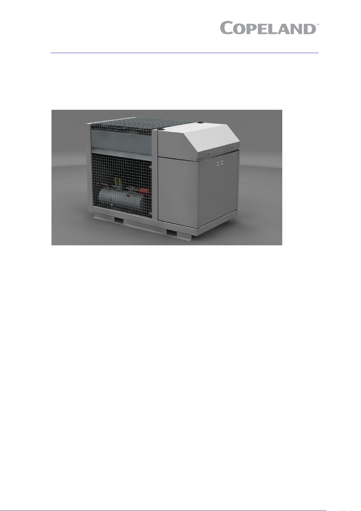
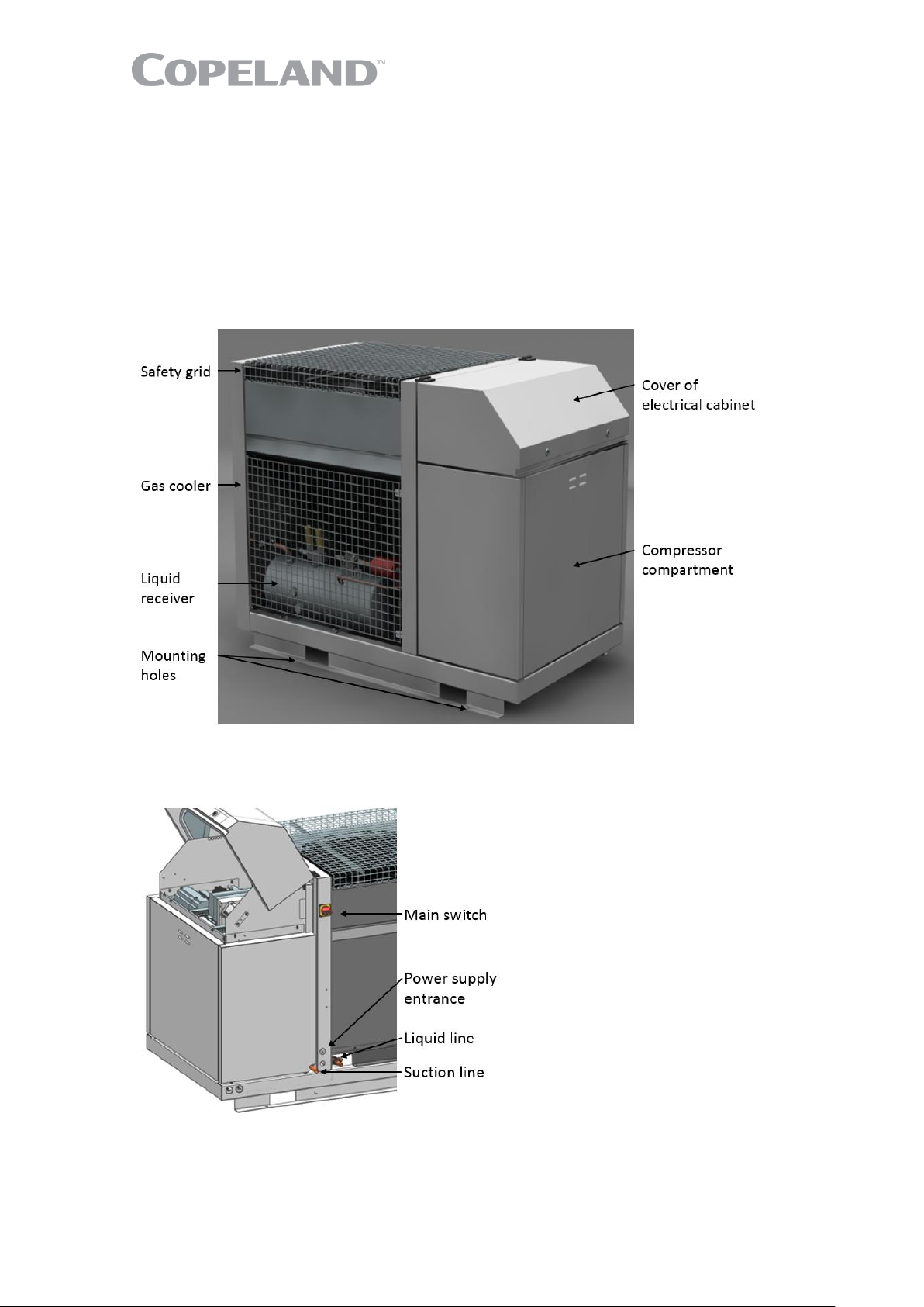
2.1 General information about Copeland EazyCool™ CO2 refrigeration unit
Emerson has developed the Copeland™ EazyCool CO2 refrigeration unit to meet primarily the
demands of the food retail and food service sectors. It is an air-cooled refrigeration unit that uses the
latest Copeland™ brand products transcritical Stream compressors with inverter. All electronic
protection and diagnostics features are built in the chassis, as well as the controls for the refrigeration
unit.
Figure 1: Front view CO2 unit
2.2 EU Ecodesign Directive 2009/125/EC
The European Directive 2009/125/EC with regard to Ecodesign requirements for professional
refrigerated storage cabinets, blast cabinets, condensing units and process chillers requires
manufacturers to decrease the energy consumption of their products by establishing minimum
energy efficiency standards. Copeland brand products condensing units are prepared and optimized
to meet the requirements of the Ecodesign Directive. The integrated variable speed fan and
condenser reduce the noise level and energy consumption significantly. This, combined with
Copeland Stream CO2 compressor technology, allows for high-efficiency operation.
These guidelines meet the requirements of Regulation 2015/1095, Annex V, section 2(a), with regard
to product information, namely:
▪ (v) ➔ See chapter 2.6 "Application range"
▪ (vi) ➔ See chapters 5.3 "Condenser fins" and 5.5 "Routine leak testing"
▪ (vii) ➔ See chapter 4.2 "Charging procedure"
▪ (viii) ➔ See chapter 7 "Dismantling & disposal"
The Ecodesign overview tables according to Annex V of Regulation 2015/1095/EU for all Copeland
EazyCool CO2 units can be found in Appendix 4.
Page 9
4 C6.1.11/0718-0619/E
2.3 Main product features
Copeland EazyCool refrigeration units are released for CO2 (R744) refrigerant only. They are
available in one cabinet size and are always equipped with one fan.
The units are designed for medium temperature applications only. The inverter is calculated to drive
the compressor in subcritical and transcritical applications.
Refrigeration unit
Refrigerant
type
Displacement
@ 50 Hz [m3/h]
Cooling
capacity*
[kW]
Nominal
power
[kW]
Max.
current
[A]
Ps
high side
[bar]
Ps
low side
[bar]
OME-4MTL-05X
R744
4.6
8.72
11
19
120/90
90
OME-4MTL-07X
6.2
11.81
14
22
OME-4MTL-09X
7.4
14.65
16
27
* Cooling capacity declared at ambient temperature 32°C, evaporating temperature -10°C, suction temperature
0°C and compressor frequency 50 Hz
Table 1: CO2 unit technical data
Refrigeration unit
Outer dimensions
length/width/height with
closed cover [mm]
Weight
[kg]
Liquid
receiver size
[litres]
OME-4MTL-05X
1579 / 954 / 1109
440
24.9
OME-4MTL-07X
450
OME-4MTL-09X
462
Table 2: CO2 unit features
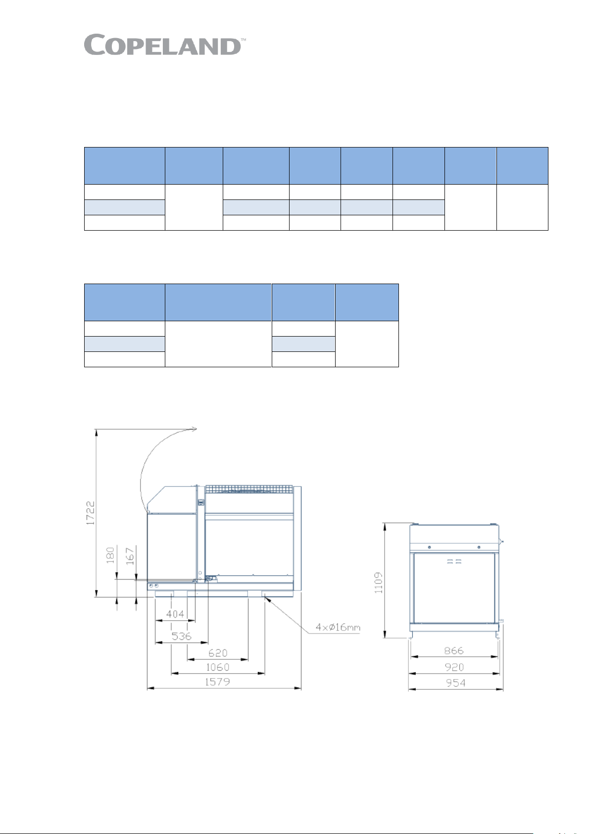
The figures hereafter show the overall physical dimensions of the CO2 refrigeration units in
millimetres.
Figure 2: Dimensions of models OME-4MTL-05X, OME-4MTL-07X & OME-4MTL-09X
NOTE: When the electrical cabinet cover is open the total height is 1722 mm. This must be
taken into consideration when deciding on the unit location, to ensure easy access to the
electrical cabinet.
Page 10
C6.1.11/0718-0619/E 5
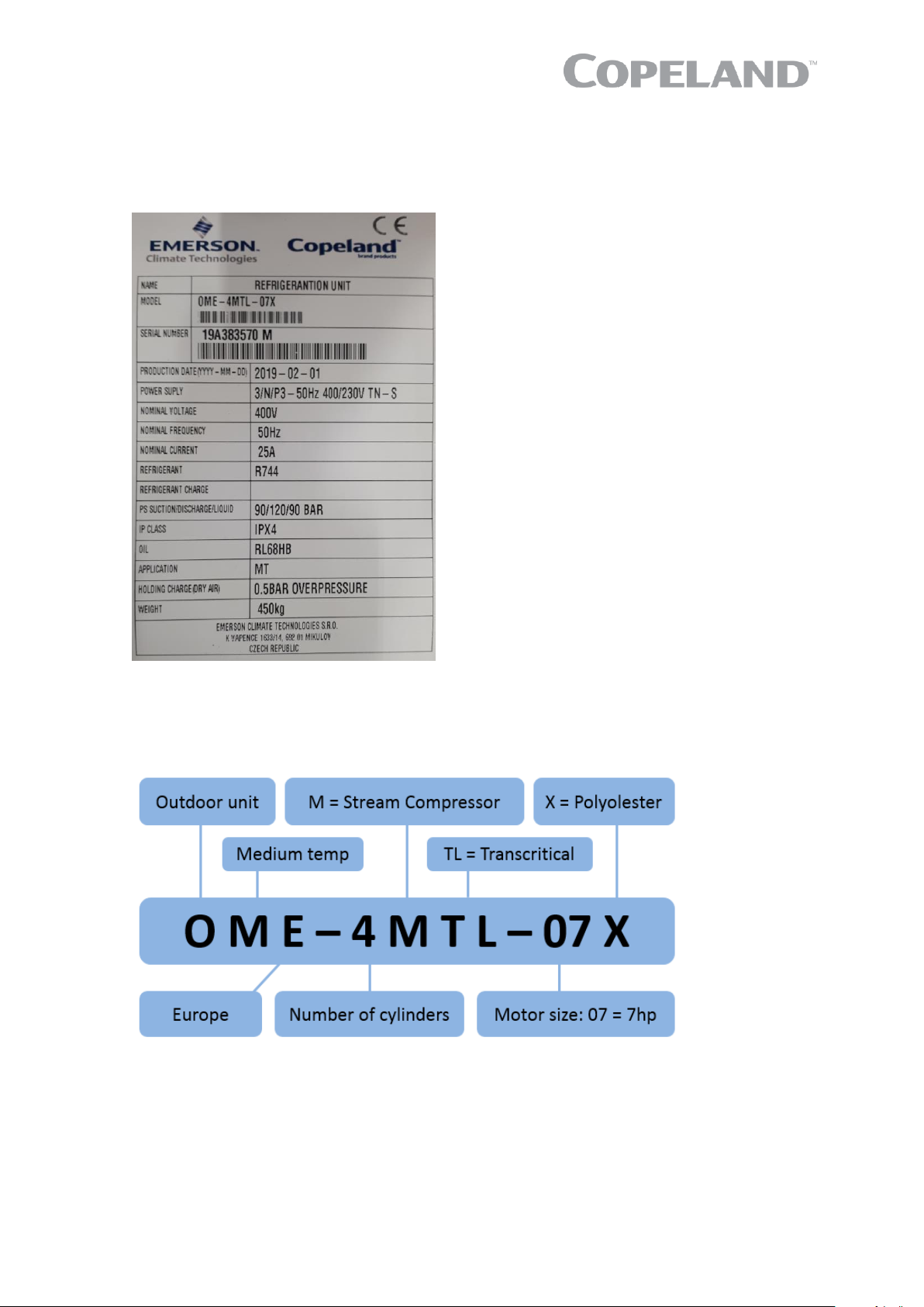
2.4 Product nameplate
The refrigeration unit nameplate shows model designation and serial number, as well as nominal
power and safety pressures.
The compressor has its own nameplate with all electrical characteristics.
Figure 3: Nameplate of CO2 units
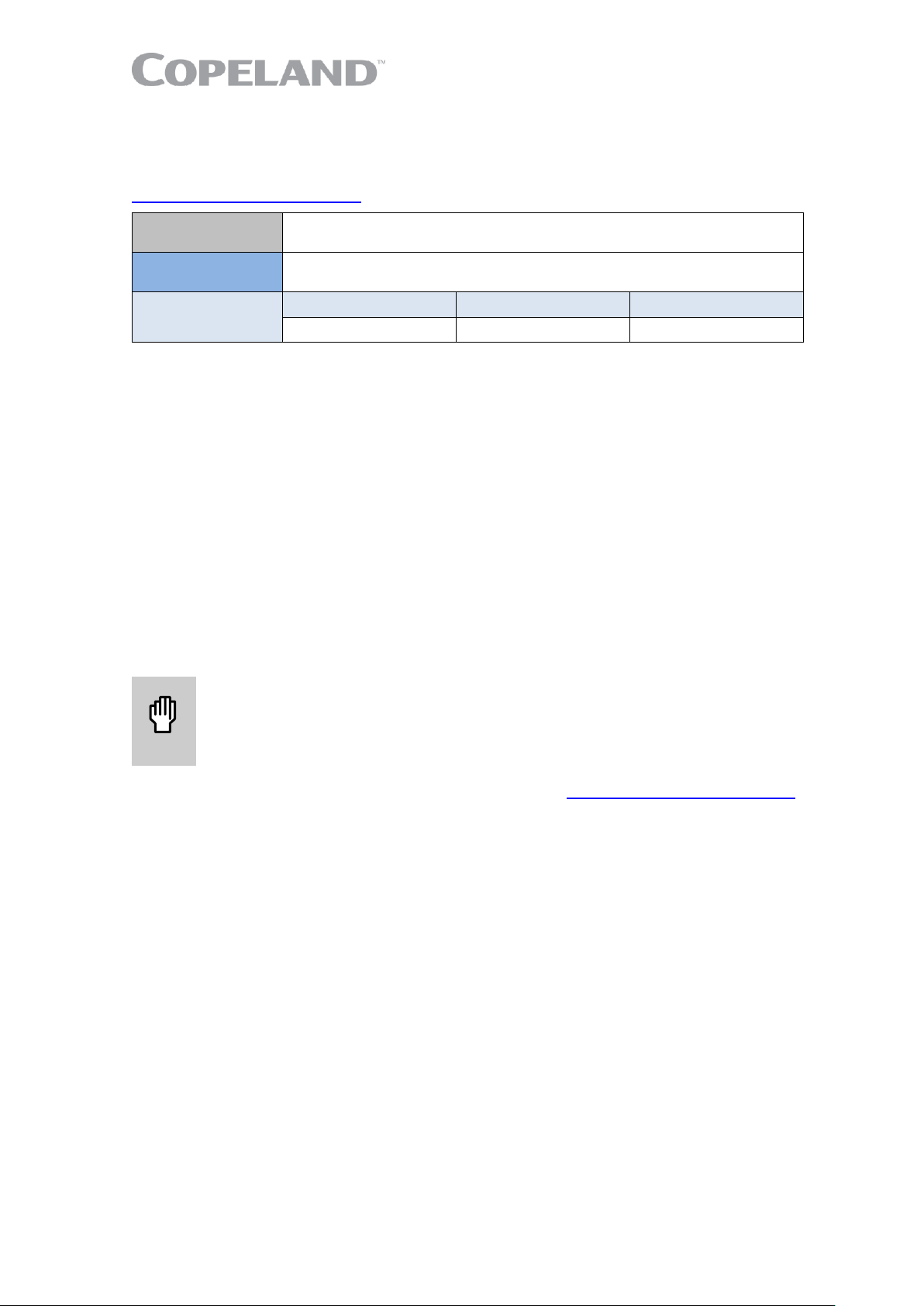
2.5 Nomenclature
The model designation contains the following technical information about Copeland EazyCool CO2
refrigeration units:
Figure 4: Nomenclature of CO2 units
Page 11
6 C6.1.11/0718-0619/E
2.6 Application range
2.6.1 Qualified refrigerant and oil
Oil recharge values can be taken from Copeland brand products Select software available at
www.climate.emerson.com/en-gb.
Qualified
refrigerant
R744 (CO2)
Qualified
servicing oil
Polyolester Emkarate RL 68 HB
Oil charge
in litres
OME-4MTL-05X
OME-4MTL-07X
OME-4MTL-09X
1.5
1.5
1.5
Table 3: Qualified refrigerant and oil
NOTE: Use only lubricants that are qualified for the product. The use of non-approved
lubricants can damage the product and will result in loss of warranty!
NOTE: The polyolester oil is very hygroscopic. Never keep the system open to the ambient. If
for any reason there is no refrigerant in the system, it is recommended to charge the system
with a protective gas, eg, inert gas N2.
The recommended quality for carbon dioxide purity class is 4.0 [(≥ 99.99%) H2O ≤ 10 ppm,
O
2
≤ 10 ppm, N
2
≤ 50 ppm] or higher.
The characterization of R744 (CO2) according to EN 378-1 is safety class A1, not flammable,
ODP = 0 and GWP = 1. High concentrations of CO2 are dangerous. This refrigerant is odourless and
colourless. Therefore the use of CO2 detectors is required.
CO2 is heavier than air. As a result, local concentrations (especially at floor level or in deeper slots =
CO2 pockets) can be higher than average values in the machine room. The ventilation system must
take this into account.
2.6.2 Application limits
WARNING
Oil dilution due to low superheat! Compressor breakdown! Low suction
superheat leads to oil dilution. Always operate the system with adequate
superheat to avoid oil viscosity decrease. Additional measures in system
design might help to avoid unacceptable lubrication conditions.
For the application envelope, please refer to Select software at www.climate.emerson.com/en-gb.
2.6.3 Recommendations for minimum suction superheat – Lubrication conditions
The operation of CO2 compressors / units at conditions where the viscosity of the oil is low might
become very harmful with regard to compressor lifetime expectancy. Indicators like oil temperature
and discharge temperature must be observed to judge about the lubrication conditions. Depending
on the application (low temp, medium temp, parallel compression, etc.…) different minimum suction
superheat values should be respected to secure maximum protection of the compressor. In general,
higher superheat on the suction inlet of a compressor provides higher safety, but the limits for the
maximum allowable discharge temperature should be considered as well (superheat has a direct
impact on discharge temperature). For medium temperature applications, an absolute minimum of
10K is recommended.
Particular attention should be paid to the following points:
▪ Measuring the suction superheat becomes more critical with larger diameters on the suction
tube. Ensure proper positioning of sensor. Sensor sleeves must be used with large diameters.
▪ The oil temperature is measured by the dedicated unit sensor and can be read out from the
Visograph display in the service menu.
▪ The discharge temperature is observed by the unit controller. The temperature on the discharge
line should never exceed 135°C (measured directly after the compressor shut-off valve). The
temperature of the discharge gas on the outlet of the valve plate is 10-15K higher than the
temperature on the discharge line.
Page 12
C6.1.11/0718-0619/E 7
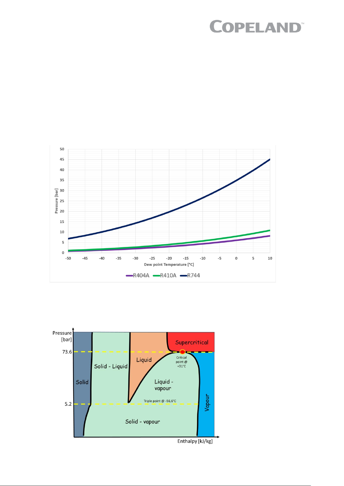
2.6.4 Pressure levels of CO2 vs. other refrigerants
Figure 5 below compares the evaporating pressures of R744 to those encountered with R410A and
R404A. It can be observed that R744 systems will require to operate at much higher pressures than
conventional systems.
Note that below a pressure of 5.2 bar, solid and gaseous R744 phases may co-exist at low
temperature. This behaviour is totally different from that observed with traditional refrigerants, and
will have important consequences on the operation, servicing and maintenance of a system working
with R744.
Gaseous R744 is 1.5 times heavier than air. Therefore, when released to the air it will concentrate
at low elevations.
R744 will form "dry ice" at -56.6°C. One kg of dry ice has the cooling capacity of 2 kg of ordinary ice.
Gaseous or liquid R744 stored under pressure will form dry ice through an auto-refrigeration process
if rapidly depressurized.
Figure 5: Pressure levels of CO
2
Figure 6 shows the thermodynamic properties (p-h-diagram) of R744. Compared to other fluids
traditionally used as refrigerants, its critical point at 31°C is very low and its critical pressure at about
73.6 bar is high.
Figure 6: Pressure/enthalpy diagram CO2
Page 13
8 C6.1.11/0718-0619/E
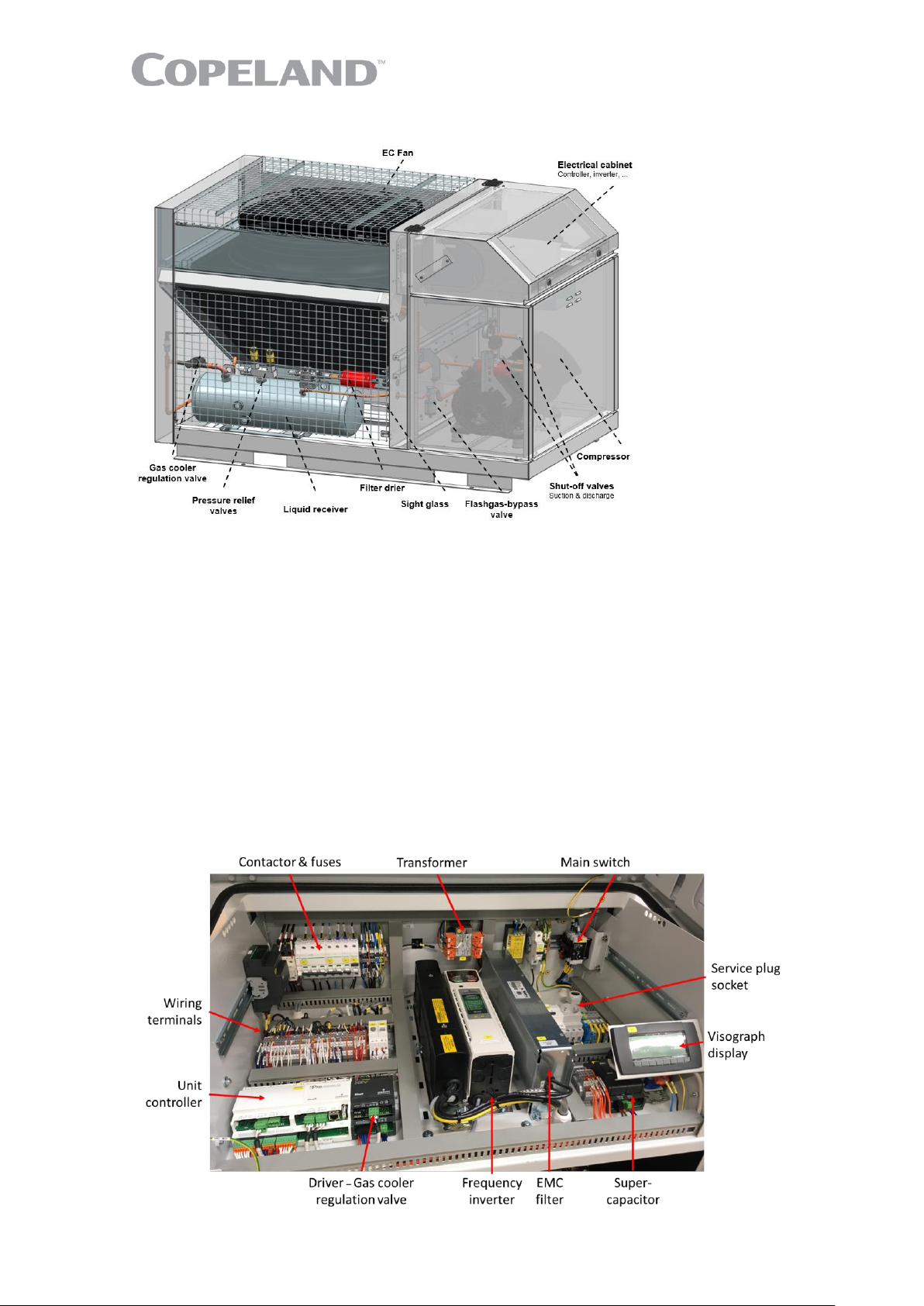
2.7 Main components description
Figure 7: Main components of CO2 unit
2.7.1 Compressor
The compressor is installed in the chamber below the electrical cabinet. The standard delivery is with
shut-off valve on discharge, CoreSense Protection module, oil watch system connected to one of the
sight glass connections. One additional sight glass on the opposite side of the compressor allows for
a visual check of the oil level. A third sight glass located in the crankcase cover will give an indication
that there is oil on the inlet of the oil splasher.
All electrical wiring is pre-assembled in the factory. A pressure relief valve (135 bar) is installed
directly on the compressor. A pressure cut-out device is installed on the discharge side of the
compressor in compliance with EN 378 requirements.
2.7.2 Electrical cabinet
The electrical cabinet is located on the edge above the compressor chamber beside the fan. All
electrical components like main unit controller, inverter, contactors, transformers, wiring terminals
and fuses are installed in this area. The electrical cabinet is covered by a hinged upper shell which
can be fixed in two opening angles.
Figure 8: Electrical cabinet
Page 14

C6.1.11/0718-0619/E 9
2.7.3 Liquid receiver
The liquid receiver (24.9 litres for the whole range of units) is installed below the condenser / gas
cooler. It is equipped with a shut-off valve on the outlet and a safety group (2 pressure relief valves
90 bar, connected to a switch-over valve).
There are 2 sight glasses in the shell of the liquid receiver to check the refrigerant level.
2.7.4 Fan
The condenser of the Copeland EazyCool CO2 refrigeration unit is equipped with an EC fan.
Figure 9: Fan design
Fan
Power
input
[W]
Maximal
current
[A]
Air flow
[m³/h]
Unit
Description
OME-4MTL-05X
FN071-6IQ.BD.V7P3
280
1.4 - 1.0
7100
OME-4MTL-07X
FN071-ZIQ.DG.V7P3
660
3.4 - 2.4
11950
OME-4MTL-09X
FN071-ZIQ.DG.V7P3
660
3.4 - 2.4
11950
Table 4: Fan specifications
Technical data
Supply frequency
[Hz]
50/60 Hz
Supply voltage
[V]
200-277
Min to max ambient temperature
[°C]
-35 to +60
ErP 2015
[-]
Yes
IP class
[-]
IP54
Fan motor type
[-]
EC
Fan blades
[-]
Plastic
Table 5: Fan technical data
2.7.5 Condenser / gas cooler regulation valve (HPV)
The high-pressure regulation valve is installed between the condenser / gas cooler and the liquid
receiver. It regulates the high pressure for optimum COP in transcritical operation.
The driver for the stepper motor valve is installed in the electrical cabinet.
The driver for the HPV is an XEV20D. It gets a signal from the iPro unit controller – see chapter 2.8
"CO2 Unit control – General".
2.7.6 Flashgas bypass valve (BPV)
The flashgas bypass valve is installed between the flashtank and the suction line to the compressor.
Without the flashgas bypass valve there is a risk of unacceptably high pressure in the flashtank in
case the ambient temperature exceeds 35°C. The flashgas bypass valve is aimed at keeping the
flashtank pressure below a set level defined by parameter GC20 (factory-set at 35 bar) at all times.
Page 15
10 C6.1.11/0718-0619/E
If a system does not require cooling capacity and the ambient temperature around the unit is high,
the pressure in the flashtank section will increase. When reaching a critical pressure limit defined by
parameter GC78 (factory-set at 40 bar) inside the flashtank during compressor stop, the compressor
will start and perform a short pumpdown cycle to reduce the pressure level in the flashtank area.
2.7.7 Housing
Copeland EazyCool CO2 refrigeration units have a new, unique design. They are equipped with an
electrical cabinet located above the compressor chamber with a hinged cover for easy and servicefriendly access. The electrical cabinet and the compressor area are accessible independently. The
fan has vertical air flow and is protected by a safety grid. The gas cooler, liquid receiver and
connected parts are freely accessible by the service technician.
Figure 10: Overview of the unit housing
Figure 11: Position of the connections
Page 16
C6.1.11/0718-0619/E 11
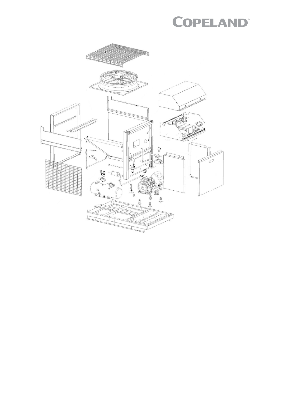
2.7.8 Exploded view of the CO2 unit
Figure 12: Exploded view of the unit
Page 17
12 C6.1.11/0718-0619/E
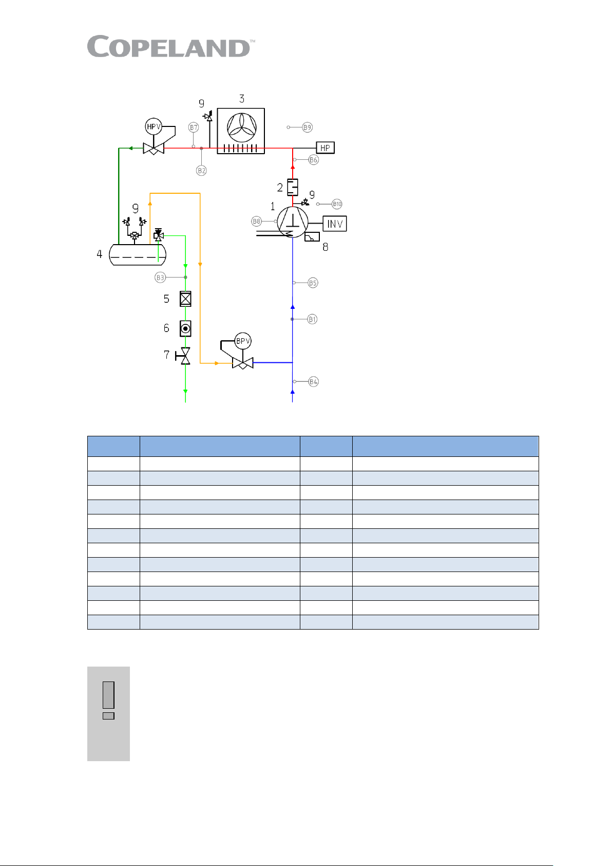
2.7.9 P&I diagram for CO2 units
Figure 13: P&I diagram for CO2 units
Position
Description
Position
Description
1
Copeland Stream compressor
INV
Compressor inverter
2
Discharge mufler
B1
Suction pressure
3
Gas cooler/condenser
B2
Discharge pressure
4
Flash tank
B3
Liquid receiver pressure
5
Filter-dryer
B4
Suction gas temperature unit
6
Sight glass
B5
Suction gas temperature compressor
7
Ball valve
B6
Discharge line temperature
8
OW5 oil watch
B7
Gas cooler temperature
9
Pressure relief valve
B8
Oil temperature
HPV
High pressure valve
B9
Ambient temperature
BPV
Bypass valve
B10
Cabinet temperature
HP
High pressure limiter
Table 6: Legend of the P&I diagram for CO2 units
2.7.10 Design pressures
IMPORTANT
Piping design pressure! Risk of CO2 blow-off! The CO2 unit liquid and
suction line piping is designed for a design pressure (Ps) of 90 bar as
pressures around 85 bar can occur during normal operation. The installer must
always consider the system liquid and suction lines in terms of maximum
operating pressure. If the system piping design pressure is lower than 90 bar,
additional safety devices are required. The CO2 unit can control different
receiver pressures depending on the application (parameter GC20).
The unit has 2 different pressure areas:
▪ The design on suction side is made for a maximum allowable absolute pressure of 90 bar at
standstill. The section after the high-pressure valve (liquid line, liquid receiver, filter drier, sight
Page 18
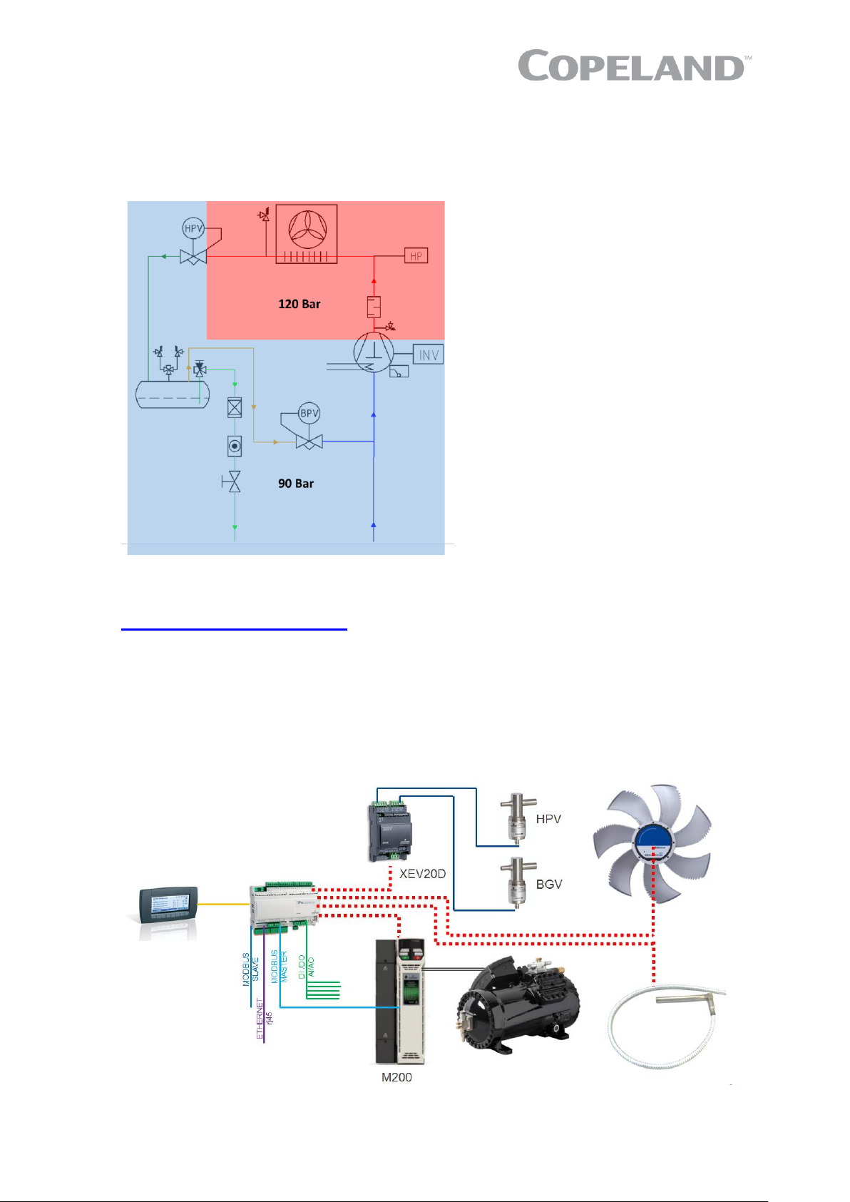
C6.1.11/0718-0619/E 13
glass) to the liquid line outlet of the unit is approved for an absolute pressure of 90 bar at
standstill too.
▪ A ½" fitting is pre-installed in the suction line for an additional pressure relief valve.
▪ The area with discharge pipe, condenser/gas cooler and high-pressure regulation valve is
approved for a maximum allowable absolute pressure of 120 bar.
Figure 14: Design pressures of CO2 unit
NOTE: The design pressure Ps is a safety-related value. The restrictions for reliable operation
of the unit are defined by the application envelope which can be found in Select software at
www.climate.emerson.com/en-gb.
2.8 CO2 Unit control – General
Copeland EazyCool CO2 refrigeration units are equipped with an iPro controller (IPR215D) and a
Visograph display. The iPro controller manages the compressor variable frequency drive through 010V and a digital signal. It also handles the high-pressure regulation which is done by a stepper
motor valve, driven by a standard driver device, controlled by iPro through CAN BUS. The stepper
motor valve driver can operate two valves simultaneously. The controller can handle gas cooler
pressure and liquid receiver pressure in parallel.
Figure 15: CO2 unit controller schematics
IPR215D
Visograph
Page 19
14 C6.1.11/0718-0619/E
2.8.1 iPro IPR215D controller description
The iPro controller is a standard IPR215D Dixell controller. A detailed manual can be found at
www.climate.emerson.com/en-gb.
The controller is factory-set for -10°C evaporating temperature. To achieve the required
temperatures, Emerson recommends to change only the evaporating temperature as the rest of the
parameters are already pre-set.
NOTE: The other factory settings can be found in Technical Information CC7.8.11 "Copeland
EazyCool™ CO2 Refrigeration Units – iPro IPR215D Controller Parameter List".
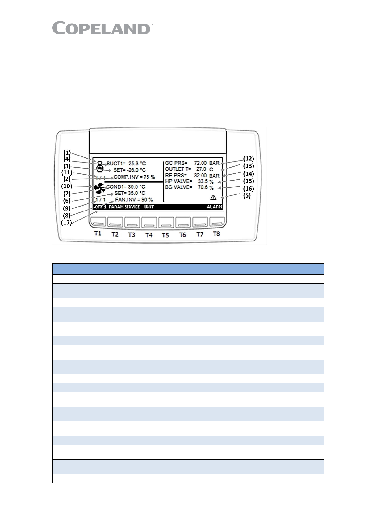
2.8.2 Visograph display description
Figure 16: Visograph display
Position
Description
Comments
1
Compressor symbol
2
Percentage of analog output
for frequency compressor
For frequency compressor. Displays the percentage
of the analog output driving the inverter.
3
Suction pressure setpoint
4
Current value of suction
pressure
5 Alarm
Displayed when an alarm occurs in suction or gas
cooler/condenser section
6
Condensing pressure setpoint
7
Current value of condensing/
gas cooler pressure
8
Percentage of analog output
for EC fan
For fan inverter. Displays the percentage of the
analog output driving the inverter.
9
Number of activated fans
10
Fan symbol
11
Number of activated
compressors and steps
12
Gas cooler pressure
The same value is displayed in "Stage Gas Cooler
Info"
13
Outlet temperature
The same value is displayed in "Stage Gas Cooler
Info"
14
Receiver pressure
15
Gas cooler regulation valve
(HPV) % opening
16
Flash gas regulation valve
(BGV) % opening
17
Operating mode
Table 7: Display description – Legend
Page 20
C6.1.11/0718-0619/E 15
OFF1
To switch the controller off. Press for 10 seconds to switch the controller off
(enabled only if parameter OT5 = yes)
PARAM
To enter the parameter programming menu
SERVICE
To enter the service menu
UNIT
Measurement unit: to switch the probe visualization and setpoint from
pressure to temperature and vice versa
ALARM
To enter the alarm menu
Table 8: Key functions
2.9 How to use the iPro IPR215D controller
2.9.1 How to change parameters
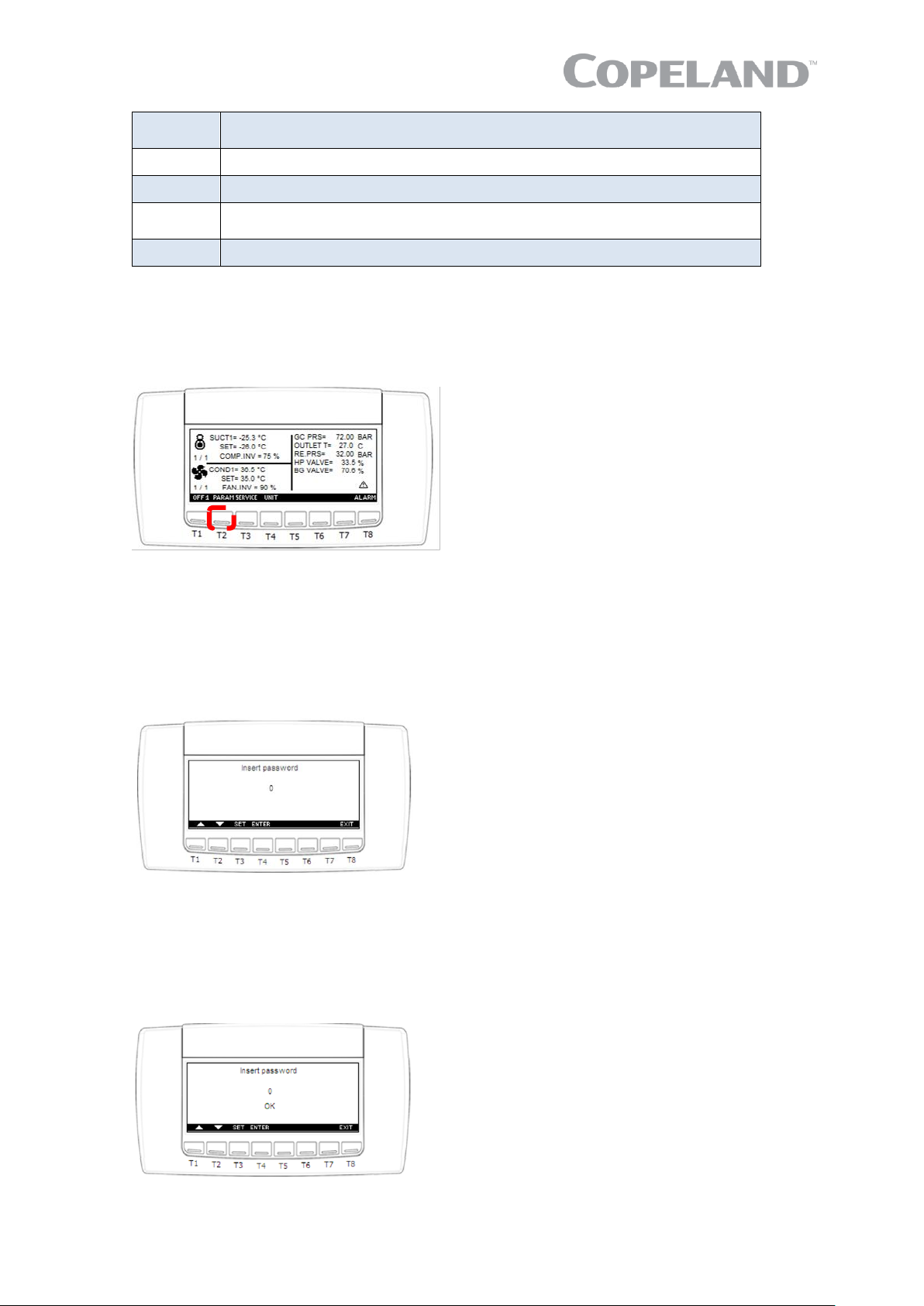
Press the PARAM key to access the programming menu.
Figure 17: iPro Parameter key
The device provides 2 programming levels:
▪ Pr1 with direct access – press Pr1 to enter this menu;
▪ Pr2 protected with a password – password set to 12 by factory.
If the password function is enabled, the following interface will be displayed when pressing the Pr2
key:
Figure 18: Password setting
To enter password:
1) Press the SET key
2) Use the UP and DOWN keys to enter password 12
3) Press the SET key to confirm password. The following interface will be displayed:
Figure 19: Password confirmation
4) Press ENTER to access the Pr2 menu
Page 21
16 C6.1.11/0718-0619/E
2.9.2 Parameter grouping
The parameters are grouped in sub-menus.
No.
Parameter grouping
No.
Parameter grouping
1
Setpoint (SETC1, SETF1)
28
Analog outputs 4 (AO4_1- AO4_26)
2
Compressor rack setup (CF1, CF16)
29
Analog outputs 5 (AO5_1- AO5_26)
3
Regulation (CF18, CF20-CF22, CF24)
30
Analog outputs 6 (AO6_1- AO6_26)
4
Display (CF26-CF27)
31
Auxiliary outputs (AR1-AR18)
5
Analog inputs (AI1-AI31)
33
Superheat alarms (ASH1- ASH16)
6
Safety digital inputs (SDI1-SDI3)
34
Gas leak detector (GLD1-GLD20)
7
Digital inputs (CDI1, CDI3)
35
Other (OT1 – OT6)
8
Compressor function
(RC1-RC4, RC35-RC38, RC45)
36
DI configuration (DIC1- DIC20)
9
Compressor safety (SL1-SL11, SL14-SL15)
37
DO configuration (DOC1- DOC15)
10
Fan function (RC9-RC33, RC43, RC47-RC55)
38
AO configuration (AOC1- AOC6)
11
Fan safety (SL12, SL13, SL16)
41
AI configuration (AIC1- AIC10)
12
Fan setting for max COP (RC56-RC61)
42
CoreSense configuration
(CO1-CO2, CO16-CO17)
13
Fan regulation band optimization with
frequency compressor (RC62-RC69)
43
ECM (ECM01-ECM9)
14
Operating mode scheduling (OMS1-OMS21)
44
XEV02 (XEV1-XEV4)
15
Alarms configuration (AC1-AC2)
45
M200 (VFD1-VFD33)
16
Compressor alarms (AL1-AL21)
46
M200 (INV1-INV33)
17
Fan alarms (AL24-AL43)
47
HTR (HTR1-HTR4)
23
Dynamic setpoint suction (DSP1- DSP4)
48
EPM (EPM1-EPM18)
24
Dynamic setpoint condenser (DSP9-DSP11)
49
Gas cooler heat reclaim (HTRC1-HTRC13)
25
Analog outputs 1 (AO1_1- AO1_26)
50
Gas cooler (GC1-GC64)
26
Analog outputs 2 (AO2_1- AO2_26)
51
Manual pumpdown (SPF1, SPF2)
27
Analog outputs 3 (AO3_1- AO3_26)
52
Unit protection (DLT1-DLT24)
Table 9: Parameter grouping
NOTE: The parameter sub-menu will be visible only if at least one parameter in the group is
visible in Pr1 or Pr2.
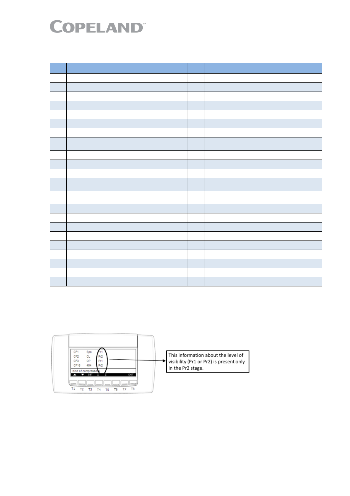
Press the SET key to access a menu. The parameters and their respective values will be displayed
(see Figure 20 below).
Figure 20: Parameter level information
▪ Press the SET key and use the UP and DOWN keys to modify a value
▪ Press the SET key again to store the new value
▪ Use the UP and DOWN keys to move to the next parameter
NOTE: The Pr2 or Pr1 message is present only in the Pr2 menu. It is possible to modify the
level of each parameter by changing Pr2 to Pr1 and vice versa.
NOTE: After pressing the EXIT key, the previous screen will be displayed again.
Page 22
C6.1.11/0718-0619/E 17
2.9.3 "Service" menu
The main functions of the controller are available from the "Service" menu and are listed below:
▪ check the values of analog outputs;
▪ check the status of compressor relays;
▪ operate a maintenance session;
▪ check the status of safety and configurable digital outputs;
▪ check the values of the probes;
▪ set the real-time clock;
▪ start a pumpdown;
▪ set the password and enable it for a defined menu;
▪ set the language;
▪ check the values of superheat probes;
▪ configure IP/Modbus address;
▪ manage / configure files;
▪ check the parameters of XEV20, XEV02, ECM, M200 and energy meter if these devices have
been configured;
▪ manage the log files;
▪ execute evacuation
▪ etc…
The following sub-menus are also available:
Probes
CoreSense setup
File management configuration
Analog outputs
CoreSense information
ip/mdb address configuration
Output (om)
Log file management
Real-time clock
Loads status
Update Visograph
Language
Digital inputs
M200 status
Password
Superheat (inactive)
Energy meter status
Gas cooler information
Pumpdown
XEV02 status
Compressor service circuit 1
Controller online/offline
Table 10: Sub-menu overview
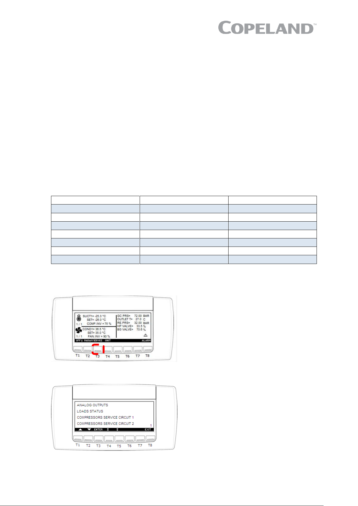
2.9.4 How to enter the "Service" menu
Press the SERVICE key to enter the "Service" menu.
Figure 21: iPro "Service" key
The following interface will be displayed:
Figure 22: iPro "Service" menu
Page 23

18 C6.1.11/0718-0619/E
2.9.5 How to check the values of analog outputs
1) Enter the "Service" menu
2) Use the UP and DOWN keys to select the "Analog outputs" sub-menu
3) Press ENTER
Figure 23: iPro "Analog outputs" screen
Analog
output
Factory setting
Description
Wiring
diagram
Function
AOC1
2 - 0-10V output inverter 1 suction – Circuit 1
VF Drive M200
X1: 25 / 21
OUT1
AOC2
5 - 0-10V output inverter condenser – Circuit 1
Fan speed
X1: 25 / 22
OUT2
AOC3
0 - Not used
Reserved
X1: 25 / 23
OUT3
AOC4
0 - Not used
AOC5
0 - Not used
AOC6
0 - Not used
Table 11: Analog outputs overview
2.9.6 How to check the status of the relays / loads
1) Enter the "Service" menu
2) Use the UP and DOWN keys to select the "Loads status" sub-menu
3) Press ENTER. The "Loads status" sub-menu displays the status of the of the relays in the
following format:
Figure 24: iPro "Loads status" screen
Digital
output
Factory setting
Description
Wiring
diagram
Function
DOC1
C1 - Inverter 1
suction - Circuit 1
Compressor (VF drive) on – Signal "Run"
X1: 71 / 70
RL1
OA1
DOC2
0 - Not used
X1: 71 / 72
RL2
OA2
DOC3
0 - Not used
X1: 71 / 73
RL3
OA3
DOC4
46 - Alarm
ALR1 – Alarm / Level 1
X1: 80 / 76
RL4
OA4
DOC5
0 - Not used
ALR2 – Alarm / Level 2
X1: 80 / 77
RL5
OA5
DOC6
0 - Not used
ALR – General alarm / Active if ALR1 or ALR2
X1: 80 / 78
RL6
OA6
DOC7
0 - Not used
X1: 80 / 79
RL7
OA7
DOC8
0 - Not used
X1: 80 / 81
RL8
OA8
DOC9
C58 - Inverter
free - Circuit 1
For fan DI – Delay adjustable
X1: 86 / 84
RL9
OA9
DOC10
0 - Not used
X1: 86 / 85
RL10
OA10
DOC11
C49 - Auxiliary
output 1
Compressor heater
X1: 90 / 87
RL11
OA11
DOC12
0 - Not used
Reserved (heat recovery, solenoid control)
X1: 90 / 88
RL12
OA12
DOC13
0 - Not used
Reserved (heat recovery, solenoid control)
X1: 90 / 89
RL13
OA13
DOC14
0 - Not used
Reserved (heat recovery, solenoid control)
X1: 90 / 91
RL14
OA14
DOC15
0 - Not used
X1: 90 / 92
RL15
OA15
Table 12: Digital outputs
Page 24

C6.1.11/0718-0619/E 19
2.9.7 How to perform a maintenance using the "Compressors service" sub-menus
The "Compressors service" sub-menus allow to perform a maintenance session consisting of:
▪ disabling an output;
▪ checking and (possibly) erasing the running hour of a load.
NOTE: Disabling an output will exclude it from the regulation.
NOTE: The "Compressors service" sub-menu can be protected by a password.
1) Enter the "Service" menu
2) Use the UP and DOWN keys to select the "Compressors service circuit 1" or "Compressors
service circuit 2" sub-menu
3) Press ENTER
Figure 25: "Compressor 1 service" menu
To disable an output during a maintenance session:
1) Enter the "Compressor service circuit 1" sub-menu
2) Use the UP and DOWN keys to select the "Load status" sub-menu
3) Press the SET key
To enable or disable a load for regulation: Press one of the following keys as per Figure 25:
▪ ENB to enable the load for regulation
▪ DISB to disable the load for regulation
Regulation with some outputs disabled: If some of the outputs are disabled, they will be excluded
from the regulation, and regulation will be performed with the other outputs.
To display the running hours of a load: The controller memorises the running hours of each load.
To see how long a load has been working:
1) Enter the "Compressor service circuit 1" sub-menu
2) Use the UP and DOWN keys to select the "Load status" sub-menu and refer to Figure 25 for
screen layout.
To erase the running hours of a load: After a maintenance session, it is usually useful to erase
the running hours of a load. Follow the steps below:
1) Enter the "Compressor service circuit 1" sub-menu
2) Use the UP and DOWN keys to select the "Load status" sub-menu
3) Press the SET key
4) Press the RST key to erase the running hours
To exit: Press the EXIT key to get back to the "Service" menu.
Page 25

20 C6.1.11/0718-0619/E
2.9.8 How to check the values of digital inputs
1) Enter the "Service" menu
2) Use the UP and DOWN keys to select the "Digital inputs" sub-menu
3) Press ENTER
Figure 26: iPro "Digital inputs" screen
Digital
input
Factory setting
Description
Wiring
diagram
Function
DIC1
o63 - Inverter suction
1 safety
VF drive failure
NO >> Normally open, closed if failure
X1: 40
DI1
DIC2
0 - Not used
HP switch
NC >> Normally closed, open if high
pressure
X1: 41
DI2
DIC3
0 - Not used
Oil alarm
NC >> Normally closed, open if oil alarm
X1: 42
DI3
DIC4
0 - Not used
Motor winding temperature alarm (KRIWAN)
NC >> Normally closed, open if motor
temperature alarm
X1: 43
DI4
DIC5
0 - Not used
VF drive under power
NC >> Normally closed, open if drive is not
powered
X1: 44
DI5
DIC6
0 - Not used
Fan alarm
Closed after power on, open if fan alarm
X1:
DI6
DIC7
0 - Not used
Fan alarm 2nd input
Closed after power on, open if fan alarm
X1: 46
DI7
DIC8
0 - Not used
Operation mode
Potential free contact controlled by user
X1: 47
DI8
DIC9
0 - Not used
X1: 48
DI9
DIC10
0 - Not used
X1: 49
DI10
DIC11
0 - Not used
DI11
DIC12
o60 - Safety inverter
condenser - Circuit 1
DI12
DIC13
0 - Not used
DI13
DIC14
0 - Not used
DI14
DIC15
o57 - Oil frequency
compressor suction Circuit 1
DI15
DIC16
0 - Not used
DI16
DIC17
o58 - Safety
frequency compressor
suction - Circuit 1
DI17
DIC18
o59 - Thermal safety
of frequency
compressor
DI18
DIC19
o74 - External alarm 1
DI19
DIC20
C95 - Operating mode
2
DI20
Table 13: Digital inputs overview
Page 26

C6.1.11/0718-0619/E 21
2.9.9 How to check the values of the probes
1) Enter the "Service" menu
2) Use the UP and DOWN keys to select the "Probes" sub-menu
3) Press ENTER. The "Probes" sub-menu displays the probe values in the following format:
Figure 27: iPro "Probes" menu
NOTE: To change the measurement unit for probes PB1, PB2, PB3 and PB4, press the UNIT
key as per Figure 27.
Analog
input
Name in
wiring
diagram
Description
Signal
Wiring
diagram
Probe type
AIC1
B1
Suction pressure
4-20mA
X1: 16 / 2
PT5-150
AIC2
B2
Gas cooler pressure
4-20mA
X1: 16 / 3
PT5-150
AIC3
B3
Liquid receiver pressure
4-20mA
X1: 16 / 4
PT5-150
AIC4
B4
Unit suction line temperature
NTC
X1: 7 / 5
NT6-55
AIC5
B5
Compressor suction line
temperature
NTC
X1: 7 / 6
NT6-55
AIC6
B6
Discharge line temperature
PTC
X1: 7 / 10
S6H
AIC7
B7
Gas cooler outlet temperature
NTC
X1: 7 / 11
NT6-55
AIC8
B8
Oil temperature
NTC
X1: 7 / 12
NT6-55
AIC9
B9
Ambient temperature
NTC
X1: 7 / 13
NG6
AIC10
B10
Cabinet temperature
NTC
X1: 7 / 14
NG6
Table 14: Probes overview
NOTE: The temperature/resistance tables for NTC & PTC sensors are available in Appendices
2 & 3.
2.9.10 How to set the date and time
1) Enter the "Service" menu
2) Use the UP and DOWN keys to select the "Real-time clock" sub-menu
3) Press ENTER
4) Use the UP and DOWN keys to set the day
5) Press SET to confirm and move to the time setting
6) Follow the same procedure to set the date and time
7) Press SET to confirm
Figure 28: iPro "Real-time clock" display
Page 27

22 C6.1.11/0718-0619/E
2.9.11 How to check the operating values of the frequency inverter M200
1) Enter the "Service" menu
2) Use the UP and DOWN keys to select the "M200 status" sub-menu
3) Press ENTER
2.9.12 Controller setting
IMPORTANT
Never adjust the suction pressure to a value that is outside of the envelope
approved by Emerson.
To change the suction pressure:
1) Press the PARAM key to access the programming menu
2) Use the UP and DOWN keys to select the Pr1 menu
3) Press Pr1 to enter this menu
4) Select setpoint (SETC1)
5) Use the UP and DOWN keys to adjust SETC1 to the desired suction pressure
NOTE: No change to the iPro HPV (gas cooler high-pressure valve) setting is required before
starting the unit.
2.9.13 Manual compressor run
IMPORTANT
Manual compressor runs are intended for maintenance purposes only!
Only qualified personnel and certified companies are allowed to perform a
manual compressor run as it can force the compressor to operate outside of
the approved envelope. In any case special care shall be taken when
performing one. In particular, never run the compressor for more than
2 minutes.
During a manual compressor run, all the safety features remain active: the controller run signal is
bypassed. Besides, during manual operation the HPV and BGV valves are closed, unless this was
manually overwritten.
To manually run the compressor, check first that the SB2 switch is switched to "I" then switch on the
SB1 switch. The compressor will immediately start at minimal speed.
Figure 29: Manual compressor operation
SB2
SB1
Page 28

C6.1.11/0718-0619/E 23
2.9.14 How to reset the controller to factory settings
1) Enter the "Service" menu
2) Use the UP and DOWN keys to select the "Conf file management" sub-menu
3) Press the SET key. The parameter map will be transferred from "Backup.conf" file to
"default_10D.conf" file.
Figure 30: Reset to factory settings
The controller will reboot, and the parameters will be reloaded from the "Param_model.conf" file.
2.9.15 How to save user’s settings
NOTE: Saving the user’s settings will overwrite the factory settings!
To update the back-up file with the current parameter map:
1) Enter the "Service" menu
2) Use the UP and DOWN keys to select the "Conf file management" sub-menu
3) Press the SET key
4) Use the UP and DOWN keys to select the "Send parameters to Backup.conf file" sub-menu
5) Press the SET key
To load the parameters from the "Backup.conf" file to the iPro rack:
1) Enter the "Load parameters from Backup.conf file" sub-menu
2) Press the SET key. The parameters will be loaded from the "Backup.conf" file.
The iPro rack will reboot and the parameters will be reloaded to the "Conf file management" file.
2.9.16 Data logging
The controller will continuously store all the alarms in an endless loop – maximum log file size 1MB.
There are 4 log files, of which only 3 can be exported:
▪ AccessLog
▪ AlarmLog
▪ ParamLog
▪ ParamAlarmLog
The ParamLog and ParamAlarmLog files contain the same variables, but:
▪ the ParamLog file has a fixed sampling rate (5 minutes);
▪ the ParamAlarmLog file stamps the info every time an alarm starts or stops.
Page 29

24 C6.1.11/0718-0619/E
No
Variable
Description
1
Suction pressure [bar]
SuctPrss_BAR
2
Condensing pressure [bar]
Cond/GCPrss_BAR
3
Liquid receiver pressure [bar]
LiqRecPrss_BAR
4
Suction temperature unit [°C]
Aux2Temp_C
5
Suction temperature compressor [°C]
SuctTemp_C
6
Discharge line temperature [°C]
DLT_C
7
Gas cooler outlet temperature [°C]
GCoutletTemp_C
8
Oil temperature [°C]
Aux3Temp_C
9
Ambient temperature [°C]
DynCondTemp_C
10
Cabinet temperature [°C]
ThermTemp_C
11
Inverter output voltage
Comp_PCT
12
Fan output voltage
Fan_PCT
13
HPV valve opening
HPV_PCT
14
BGV valve opening
BGV_PCT
15
Inverter M200 output power
M200power_kW
16
Inverter M200 output frequency
M200freq_Hz
Table 15: Data logging parameters (in addition to the date and hour)
2.9.17 Active alarm(s) log menu
NOTE: This function is not available from the Visograph screen.
The iPro rack can store up to 1 MB of alarm data in a log file, including the start and end dates of
each alarm. This file can be exported through the Dixell website integrated on a memory card or via
the USB port using the "Log file management" sub-menu.
To save the alarm log file into a USB key:
1) Enter the "Service" menu
2) Use the UP and DOWN keys to select the "Log file management" sub-menu
3) Press ENTER
4) The following interface will be displayed: "Send alarm log to usb" (see Figure 31)
Figure 31
5) Use the UP and DOWN keys to select the function
6) Press ENTER. If the USB key is not ready the following message will be displayed:
▪ "Warning! USB not ready".
7) To save the log file, follow the steps as described on the display. At the end of the process,
one of the following messages will be displayed:
▪ "Send completed successfully!" ➔ Saving was successful.
▪ "Send error!" ➔ Saving failed.
Page 30

C6.1.11/0718-0619/E 25
2.10 iPro IPR215D controller – Functionality
The iPro IPR215D controls the complete refrigeration unit. It provides a lot of customization features
like alarms and special operating modes. Thanks to the high degree of flexibility, the user can either
use the factory-set alarms or set up his own alarms according to the application requirements.
The following functionalities are pre-programmed:
▪ suction pressure control
▪ fan speed / gas cooler control
▪ alarms
The refrigeration unit is able to operate in both subcritical and transcritical modes. The setpoint for
switching from subcritical to transcritical operation is adjustable (GC1). The factory setting for this
trigger point is 27°C, measured over gas cooler outlet sensor B7 (AIC7). The (adjustable) hysteresis
(GC2) for the (GC1) setpoint is 1K.
Figure 32: Switching from transcritical to subcritical mode
NOTE: A system control very close to the critical point may result in a loss of capacity and
unstable system behaviour. This can be overcome by setting GC3 to a higher value (76-80 bar)
or by dynamic offset using parameters GC16 and GC17.
2.10.1 Suction pressure control
2.10.1.1 Standard suction pressure control
The setpoint for suction pressure control is parameter SETC1, the factory setting is -10°C.
SETC1 Compressor Circuit 1 setpoint
Range: -15°C to -5°C
Unit: [°C]
Depending on the number of evaporators, ie, on the suction side internal volume, a rapid decrease
of the suction pressure during compressor start might occur. This can result in low-pressure cut-out
before reaching stable regulation conditions. The acceleration of the compressor speed can be
adjusted by decreasing the value of SETC1.
2.10.1.2 Automatic pumpdown
If parameter SPF4 is set to "yes" a pumpdown will be performed before stopping the compressor. If
it is set to "no", only the manual pumpdown and the automatic pumpdown during the bypass
optimization function will be performed.
SPF1 Compressor setpoint during pumpdown
Range: -70°C to -10°C
Unit: [°C]
Page 31

26 C6.1.11/0718-0619/E
Parameter
Description
Level
Min value
Max value
Factory
setting
SPF1
Differential to be subtracted from
the compressor setpoint
Pr1
0K
20K
8K
SPF2
Compressor frequency during
pumpdown
Pr1
0%
(min speed
25 Hz)
100%
(max speed
60 Hz)
0%
SPF3
Pumpdown maximum time
Pr1
0 min
25 min
3 min
SPF4
Automatic pumpdown
Pr1
yes
SPF5
Pumpdown offset
Pr2
0°C
40°C
20°C
Table 16: Pumpdown parameters
2.10.2 Pumpdown mode
The pumpdown function of the CO2 refrigeration unit does not work in the same way as in units using
standard refrigerants. Based on the ambient temperature and the compressor setpoint, the controller
calculates two different pumpdown setpoints:
▪ setpoint based on ambient temperature = T
Amb
– SPF5
▪ setpoint based on compressor setpoint = SETC1 – SPF1
The lowest pumpdown setpoint will always be applied. The following diagram illustrates the controller
logic:
Figure 33: Controller logic for the pumpdown function
NOTE: The pumpdown setpoint will never be lower than what parameter RC02 allows.
2.10.3 Fan speed / gas cooler control
2.10.3.1 Subcritical operation
For gas cooler outlet temperatures typically below 27°C (AIC7 < GC1 - GC2), the system operates
in subcritical mode.
▪ The CO2 refrigerant condenses inside the gas cooler (condenser).
▪ The condenser outlet temperature is read by the probe AIC7, which defines the fan speed.
▪ The gas cooler valve HPV will keep a certain sub-cooling of the refrigerant (about 2-3K) in order
to create pressure differential between the gas cooler and the flash tank.
▪ The fan speed setpoint is +5°C with a proportional band of +5K, ie, down to 7.5°C, the fan will
always run at full speed, unless the ambient temperature goes down below 12°C. In this case
the fan speed will be reduced. At an ambient temperature of -15°C the maximal fan speed is
reduced down to 50%.
SETF1 Condenser Circuit 1 setpoint
Range: +5°C to +25°C
Unit: [°C]
-18°C < 0°C
Controller will perform
pumpdown down to -18°C
Ambient condition:
T
Amb
= 20°C
SPF5 = 20K
Compressor setpoint:
SETC1 = -10°C
SPF1 = 8K
Pumpdown setpoint based
on ambient temperature:
T
Amb
– SPF5 = 0°C
Pumpdown setpoint based on
compressor setpoint:
SETC1 – SPF1 = -18°C
Page 32

C6.1.11/0718-0619/E 27
Figure 34: Sensoring in subcritical mode
2.10.3.2 Transcritical operation
For temperatures typically above 27°C (AIC7 > GC1), the system operates in transcritical mode.
▪ According to the gas cooler outlet temperature detected by the AIC7 probe, the high-pressure
valve modulates to maintain a pressure that maximizes the COP (Coefficient of Performance).
▪ The fan speed setpoint is +5°C with a proportional band of +5K.
2.10.3.3 Transcritical operation with flashgas bypass
In transcritical operation mode in CO2 systems, the liquid receiver becomes a flashtank, in which the
liquid phase is separated from the gas phase. In high ambient conditions, the amount of gas will
increase due to the thermodynamic properties of CO2. Flashgas ratios of 50% or more are not
unusual. Typically, the flashgas is removed to the compressor suction side to keep the pressures in
the flashtank at acceptable levels.
Bypassing flashgas will reduce the mass flow coming from the cold rooms/cabinets. This necessary
process will however reduce the total system efficiency. The flashgas-bypass valve limits the
maximum pressure in the flashtank to 43 bar (adjustable with parameter GC20 according to
application and piping design).
▪ The fan speed setpoint is +5°C with a proportional band of +5K.
2.10.4 Alarms
In the event of an alarm, the alarm symbol will be flashing on the main display.
Figure 35: iPro Alarm flashing symbol
Page 33

28 C6.1.11/0718-0619/E
Press the ALARM key to enter the "Alarm" menu:
Figure 36: iPro "Alarm" key
The header of the corresponding menu will be flashing. Four alarm menus are available from the
display:
▪ Compressor alarms Circuit 1
▪ Fan alarms Circuit 1
▪ Alarms Circuit 1
▪ Generic alarms
An additional alarm menu is available from the iPro internal webpage.
1) Use the UP and DOWN keys to select the desired alarm section
2) Press ENTER to confirm and access the alarm sub-menu
Figure 37: Active alarms screen
The alarm menu will display the active alarm in the following format:
▪ Column 1: Alarm code
▪ Column 2: Alarm description
Several alarms are pre-programmed in the unit. The configuration can easily be adjusted to the user’s
needs. The factory settings only consider a general compressor alarm (Parameter AL09 "Relay for
temperature/pressure compressors alarms"), and a general fan alarm, both connected to "ALR".
Alarm
Factory setting
Description
Wiring
diagram
Function
ALR1
ALR1
X4: 80 / 76
ALR1
R4
ALR2
ALR2
X4: 80 / 77
ALR2
R5
ALR3
ALR
X4: 80 / 78
ALR
R6
ALR4
Reserved
X4: 80 / 79
ALR4
R7
ALR5
Reserved
X4: 80 / 81
ALR5
R8
PFC
Potential free contact (source 24VAC (69))
Operation mode
X4: 69 / 47
PFC
Potential free contact (source 24VAC (69))
Not used
X4: 69 / 48
PFC
Potential free contact (source 24VAC (69))
Not used
X4: 69 / 49
Table 17: Alarm overview
Compressor alarm: The activation of the relay for temperature/pressure compressor alarms can be
set in the "Compressor alarms" menu.
Parameter AL10 allows for an additional alarm for "Running hours for compressor maintenance"
(factory setting >> 0 = not used). To activate the maintenance alarm change AL10 from "nu - not
used" to ALR1 or ALR2.
Page 34

C6.1.11/0718-0619/E 29
Fan alarm: The activation of the relay for temperature/pressure fan alarms can be set in the "Fan
alarms" menu.
NOTE: The OME-4MTL-05X will not trigger any fan alarm because there is no alarm contact in
the fan in this model.
Alarm for faulty probe: Another alarm is connected to "ALR" in case a probe is faulty. Parameter
AL11 "Alarm relay for faulty probe" is set to ALR.
2.11 iPro IPR215D controller – Peripheral devices
The iPro unit controller interacts with several devices inside the electrical cabinet. These guidelines
only provide general information about and short descriptions of the peripheral devices. Dedicated
technical documentation (manuals, operating instructions) for those devices is available at
www.climate.emerson.com/en-gb.
2.11.1 XEV20D Stepper valve actuator
The XEV20D stepper valve actuator communicates with the unit controller via CAN Bus. It is intended
either for bipolar stepper valves or unipolar stepper valves. Both the gas cooler regulation valve and
the flashgas-bypass regulation valve are driven by the XEV20D.
Figure 38: XEV20D stepper valve actuator
2.11.2 Variable frequency drive M200
The Emerson variable frequency drive M200 has been designed for applications that require flexible
integration with systems via industrial Ethernet protocols and fieldbuses, together with advanced
RFC-A open-loop motor control. Connection to RS485 networks using Modbus RTU allows for
communication with the iPro unit controller.
The M200 frequency inverter uses the 0…10V input signal of the iPro controller to adjust the
compressor speed to the requirements. For more details see the M200 Inverter Handbook.
NOTE: The variable frequency drive should not be used to change the system settings. All
required changes and adjustments can be made directly on the system controller via the
Visograph display.
2.11.3 Main contactor and circuit breakers
The components of the electrical main load circuit are located in the left back area of the electrical
cabinet. Before commissioning some electrical components need power supply to enable heating up
the compressor oil sump and to manually open the gas cooler (HPV) and the flashtank valve (BPV)
on demand, eg, tightness test and evacuation procedure.
NOTE: For safety reasons never switch the F1 (compressor) or F3 (fans) circuit breaker on
without a minimum refrigerant charge inside the system.
NOTE: The unit main switch must always be switched on to provide power to the control chain
and dedicated electrical components.
Page 35

30 C6.1.11/0718-0619/E
Figure 39: Main contactor and circuit breakers
2.12 Compressor safety
2.12.1 Compressor motor protection
Copeland EazyCool CO2 units are equipped with a Stream 4MTL compressor including CoreSense
Protection technology.
All relevant electrical protection features are covered by the Emerson M200 variable frequency drive.
For more details see the M200 Inverter Handbook.
The discharge line temperature is monitored and controlled by the iPro controller.
The different areas of the system are limited by different design pressures (Ps) – see chapter 2.7.10
"Design pressures" for details. There are different levels of protection and control to keep the
pressures within the approved envelope at all times.
2.12.2 High-pressure safety (type-approved pressure limiter)
A type-approved pressure limiter (according to EN 12263) with automatic reset is installed on the
compressor. It is an Alco normally-closed switch.
The pressure cut-out is set to 114 bar and the cut-in is set to 107 bar.
Figure 40: High-pressure cut-out device
2.12.3 High-pressure safety control
There are 3 pressure transmitters assembled in the unit. These transmitters are used for system
control purposes as well as for safety. They are located on the suction side (B1 = AIC1), between
the gas cooler and the high-pressure regulation valve (B2 = AIC2), and on the liquid receiver outlet
(B3 = AIC3).
The factory setting of the high pressure is slightly below the activation setpoint of the high-pressure
safety switch.
The transmitter on the liquid receiver is also used to limit the liquid receiver pressure during operation
by means of the flashgas-bypass.
Page 36

C6.1.11/0718-0619/E 31
Figure 41: Pressure transmitters in the CO2 unit
2.12.4 Pressure relief valve – High-pressure side
A 120-bar pressure relief valve is installed in the gas cooler outlet. This valve protects the highpressure side including the gas cooler. In case of blocked HPV the high-pressure cut-out will switch
the compressor off before the pressure relief valve opens.
The pressure relief valve will reach 100% of blow-off capacity when the maximum allowable pressure
Ps of the compressor is exceeded by 10% (opening at 1.0 x Ps, max capacity at 1.1 x Ps).
Figure 42: Pressure relief valve on high-pressure side
2.12.5 Pressure relief valve – Liquid receiver
There are two pressure relief valves (90 bar) on the liquid receiver, connected on a changeover
valve. In case of refrigerant blow-off, this allows for easy replacement of the relief device without
interruption of unit operation by using the second valve.
Typically, after a blow-off event, the relief devices are not 100% tight anymore. Therefore component
exchange after activation is recommended. The thread connections on the changeover valve and
pressure relief valve are M24x1.5.
Page 37

32 C6.1.11/0718-0619/E
Figure 43: Liquid receiver with safety group
Figure 44: Pressure relief valves with changeover valve
2.12.6 Low-pressure safety control
As on discharge and liquid sides, a suction pressure transmitter (B1 = AIC1) provides information
about suction pressure to the system controller. This value is used to evaluate the load requirement
and to protect the unit / system against low pressure on suction side.
Figure 45: Low side pressure transmitter
Page 38

C6.1.11/0718-0619/E 33
2.13 Oil level monitoring device OW5 TraxOil
The compressor in the Copeland EazyCool CO2 refrigeration unit is equipped with an OW5 TraxOil
oil level monitoring system. This device is intended to prevent the compressor from operating with
insufficient oil. The OW5 uses a hall sensor to measure the oil level. Unaffected by foaming oil or
light, a magnetic float changes its position according to the oil level. The hall sensor converts the
magnetic field changes into an equivalent signal, which is used by the integrated electronic controller
to monitor and display the actual oil level with LEDs.
In case of low oil level and after a delay time of 120 seconds the OW5 will generate an alarm which
will make the unit controller stop the compressor immediately.
This alarm can be displayed on the Visograph like any other alarm of the unit.
Figure 46 below depicts the sight glass level control zones. Table 18 describes the LED code legend.
Figure 47 shows the OW5 TraxOil mounted on the compressor.
Figure 46: Sight glass level control zones
LED’s
Status
Function
Alarm
•
Oil level in green zone (60 - 40%)
OK
• •
Oil level in green zone (60 - 40%)
OK
•
Oil level in yellow zone (40 - 25%)
Warning
•
Oil level in red zone (25 - 0%)
Alarm
Yes, delay
20 to 120 sec
Table 18: LED code legend
Figure 47: OW5 TraxOil mounted on the compressor
Page 39

34 C6.1.11/0718-0619/E
3 Installation
WARNING
High pressure! Injury to skin and eyes possible! Be careful when opening
connections on a pressurized item. Never install the unit at such a height that
if the pressure relief valve opens, the gas flow can reach an individual’s head.
IMPORTANT
Always install the unit in such a way that all installation, commissioning and
servicing works can be carried out safely and easily.
Copeland EazyCool CO2 refrigeration units are delivered with a holding charge of neutral gas.
The refrigeration unit should be located in such a place to prevent any dirt, dust, plastic bag, leaves
or papers from covering the condenser / gas cooler and its fins.
A clogged condenser / gas cooler will increase the refrigeration temperature and/or the gas cooler
outlet temperature which could lead to a high-pressure switch tripping. Clean the condenser fins on
a regular basis.
The unit must be installed without restricting the airflow. Harmful environmental conditions like very
low or high temperatures should also be avoided.
The place of installation has to be level and horizontal. The unit must be secured to the ground to
avoid any movement of the base frame. The ground needs to be designed for the weight of the unit.
It might be necessary to install additional vibration absorbers between the unit and the ground to
avoid the transmission of vibration to the rest of the building.
The place of installation should be sufficiently lit and should allow easy access for service and
maintenance work.
In case of installation in a machine room, standard EN 378-3 and all additional national regulations
shall be observed.
A risk assessment of the place of installation has to be conducted before actual system installation.
It should be documented for local authorities and should contain safety-related measures to avoid
risks. The risk assessment of the unit itself has been performed by the manufacturer.
3.1 CO2 Refrigeration unit handling
3.1.1 Transport and storage
WARNING
Risk of collapse! Personal injuries! Move units only with appropriate
mechanical or handling equipment according to weight. Keep in the upright
position. Respect stacking loads according to Figure 48. Do not stack
anything on top of the unit packaging. Keep the packaging dry at all times.
Respect the maximum number of identical packages which may be stacked on one
another, where "n" is the limiting number:
▪ Transport: n = 0
▪ Storage: n = 0
Figure 48: Maximum stacking loads for transport and storage
3.1.2 Weights
Unit
Net weight [kg]
OME-4MTL-05X
440
OME-4MTL-07X
450
OME-4MTL-09X
462
Table 19: Weights
Page 40

C6.1.11/0718-0619/E 35
3.1.3 Lifting
Always lift the unit by points marked with red arrows on pictures below.
Figure 49: Lifting points for CO2 units
When lifting the unit with slings, always use the spreader bar mounted above the unit to avoid
squeezing the unit.
Figure 50: Lifting unit with slings and centre of gravity
Page 41

36 C6.1.11/0718-0619/E
3.2 Refrigeration piping connections
3.2.1 Refrigeration piping installation and connections
WARNING
High pressure! Risk of personal injury! The units are pressurized with dry
air. Be careful when opening connections on a pressurized item.
IMPORTANT
Tubing quality! Installation contamination! All interconnecting piping
should be of refrigeration grade, clean, dehydrated and must remain capped
at both ends until installation. Even during installation, if the system is left for
any reasonable period of time, eg, 2 hours, pipes should be re-capped to
prevent moisture and contaminant from entering the system.
Connection sizes! Unsuitable refrigerant flow rate! Do not assume that the
service connection sizes on the unit (at the service valves) are in fact the
correct size to run the interconnecting refrigeration pipes. The service valve
sizes have been selected for convenience of installation and in some cases
these may be considered too small. However, for the very short pipe run within
the units these service connection sizes are adequate. All interconnecting
piping should be sized to satisfy the duty required.
IMPORTANT
Piping design pressure! Risk of CO2 blow-off! The CO2 unit liquid and
suction line piping is designed for a design pressure (Ps) of 90 bar as
pressures around 85 bar can occur during normal operation. The installer must
always consider the system liquid and suction lines in terms of maximum
operating pressure. If the system piping design pressure is lower than 90 bar,
additional safety devices are required. The CO2 unit can control different
receiver pressures depending on the application.
The pipes should be sized to ensure optimum performance and good oil return. The sizing must also
take into account the full capacity range through which a particular unit will need to operate.
The piping on the unit is made of K65, a high copper alloy tube designed for high operating pressures.
This kind of tube is more rigid than a standard copper tube; this must be considered for the design
and fixation of the piping system.
Figure 51: Piping connections
Unit
Suction line (ODS)
Liquid line (IDS)
OME-4MTL-05X
3/4" (19.05 mm)
5/8" (15.875 mm)
OME-4MTL-07X
3/4" (19.05 mm)
5/8" (15.875 mm)
OME-4MTL-09X
7/8" (22.23 mm)
5/8" (15.875 mm)
Table 20: Piping connections sizes
Page 42

C6.1.11/0718-0619/E 37
3.2.2 Brazing recommendations
IMPORTANT
Blockage! Compressor breakdown! Maintain a flow of oxygen-free nitrogen
through the system at very low pressure during brazing. Nitrogen displaces
the air and prevents the formation of copper oxides in the system. If allowed
to form, the copper oxide material can later be swept through the system and
block screens such as those protecting capillary tubes, thermal expansion
valves, and accumulator oil return holes.
Contamination or moisture! Bearing failure! Do not remove the plugs until
the compressor is set into the unit. This minimises any entry of contaminants
and moisture.
1) Remove the liquid connection cap.
2) Remove the suction connection cap.
Figure 52
3) Open the liquid line valve mid-way. Care should be taken to avoid the holding charge releasing
too quickly.
4) Be sure tube fitting inner surface and tube outer surface are clean prior to assembly.
5) Both tubes are extended from the condensing unit housing, therefore Emerson recommends
isolating the housing by using a wet cloth on the copper tubing.
6) Use a double-tipped torch.
Recommended brazing materials: see Table 21 below and recommendations specific to K65 at:
http://www.wielandthermalsolutions.com/commonmedia/content/media/en/prospekte_2/gbrohre/prospekte/untersuchu
ngsergebnisse_wieland_k65_11.pdf
Brazing alloy
DIN EN
ISO 17672
DVGW* number
Working
temperature
[°C]
Composition [% by weight]
Ag
Cu
Zn
Sn
P
BrazeTec
4576
Ag145
DV-0150CM0043
670
45
27
25.5
2.5
-
BrazeTec
3476
Ag134
DV-0150CM0045
710
34
36
27.5
2.5
-
BrazeTec
4404
Ag244
DV-0150CM0044
730
44
30
26 - -
BrazeTec S
15
CuP284
-
700
15
80 - -
5
BrazeTec S 5
CuP281
-
710
5
89 - - 6 BrazeTec S 2
CuP279
DV-0105CL0475
740
2
91.7 - -
6.3
Flux
DIN EN
1045
DVGW* number
Active
temperature
[°C]
Comments
BrazeTec h
FH10
DV-0101AU2227
550-970
Flux residues are corrosive and must be
removed
* DVGW = German Technical and Scientific Association for Gas and Water
Table 21: Extract of the recommendations for acceptable brazing alloys and flux
Suction line
Liquid line
Page 43

38 C6.1.11/0718-0619/E
Figure 53: Brazing – Sectional view
3.3 Electrical connection
WARNING
Earth leakage current! Danger of electric shock! This product includes a
three-phase frequency drive. Additional protection devices could be necessary.
This must be decided by the electrical network supplier or by the electrician
company which provides the electrical connection.
Copeland EazyCool CO2 refrigeration units can cause earth leakage currents, both AC and DC, due
to the presence of an inverter and an EMC filter in the system. In case a three-phase inverter drive
is used, an AC/DC-sensitive Residual Current Device (RCD) should be used on the power supply
side. The RCD can be either type B with the frequency band up to 20 KHz (Siemens/SIQUENCE-
0.3-B or Schneider/Acti9 RCCB-ID for instance), or type B+.
A delay of at least 50 ms should be incorporated to prevent spurious trips. The leakage current is
likely to exceed the trip level if not all the phases are energized simultaneously.
3.3.1 Power supply connections
WARNING
Electrical cabinet cover open! Danger of electric shock! Always make sure
the electrical cabinet cover is properly closed before starting the unit.
The electrical connection of the refrigeration unit to the power supply must be made by qualified
technicians in compliance with the valid electrical standards, eg, DIN EN 60204-1.
Additionally, the voltage drop and temperatures must be considered for cable selection. The nominal
power and current are shown in Table 22 hereunder:
Unit
Nominal power
[kW]
Maximum current
[A]
Power supply
OME-4MTL-05X
11
19
3/N/PE~50 Hz
400/230V TN-S
OME-4MTL-07X
14
22
OME-4MTL-09X
16
27
Table 22: CO2 unit nominal power and current
Copeland EazyCool CO2 units are designed to be connected to one of the following power supplies:
▪ TN-S system with 380-420V / 3Ph / 50 Hz + N + PE or
▪ TN-C system with 380-420V / 3Ph / 50 Hz + PEN
A voltage tolerance of ± 10% is acceptable.
The circuit breaker and the main switch on the backside of the unit must be switched off before
opening the hinged front cover and connecting the power supply cable.
The power cable should enter the electrical box through a rubber grommet.
Page 44

C6.1.11/0718-0619/E 39
NOTE: When a TN-C system is applied a jumper (part of the delivery) must be added between
N & PE (X5.N & X5.PE) as per Figure 54.
Figure 54: Power supply terminals with jumper
3.3.2 Electrical wiring
Ensure that the neutral wire "N" and the ground protection wire "PE" are connected to the main switch
before commissioning.
3.3.3 Electrical protection standard (protection class)
▪ Units: IP class IPX4.
▪ Stream 4MTL compressor terminal box: IP54 according to IEC 34.
▪ Fan: IP54 according to IEC 34.
3.4 Location & fixings
IMPORTANT
Dust and dirt contamination! Unit life reduction! The unit should always be
installed in a location where clean air flow is ensured. External fouling of the
condenser fins leads to high condensing temperatures or pressures and will
reduce the lifetime of the unit.
It is mandatory to keep a clearance space around the unit as shown in Figure 55, dimensions in red
colour. Both service access and airflow have been considered in making these recommendations.
Where multiple units are to be installed in the same location, the contractor needs to consider each
individual case carefully. There can be many variations of unit quantities and available space and it
is not the intention of this manual to go over these. However, in general terms, air bypass around
each condenser and between the units should always be avoided.
Ideally, the unit should be mounted level on a solid concrete slab with anti-vibration pads between
unit feet and concrete. However, the refrigeration unit has also been designed for wall mounting on
suitable brackets. In this case, it is equally important that the dimensional guidelines given in
Figure 55 are followed and that additional consideration is given for possible air recycling if units are
installed one above the other. Wall mounting brackets are not included in the standard delivery.
Access area
1579
954
Page 45

40 C6.1.11/0718-0619/E
Figure 55: Dimensions and distances required for unit installation (in mm)
Another factor to consider in finding a good installation site is the direction of the prevailing wind. For
example, if the air leaving the condenser faces the prevailing wind, the air flow through the condenser
can be impeded, causing high refrigeration temperatures and ultimately resulting in reducing the
lifetime of the unit. A baffle is a remedy for this situation.
1600
Page 46

C6.1.11/0718-0619/E 41
4 Start-up & operation
WARNING
High pressure! Risk of personal injury! Always keep sufficient distance
from the pressure relief valve to avoid serious injury in the event of a sudden
pressure release.
WARNING
Hot surfaces! Burning! Do not touch the compressor’s heads or discharge
line as their surfaces can reach high temperatures both during operation and
at standstill.
WARNING
High noise level! Risk of hearing damage! In case of pressure release of
the pressure relief valve, a sudden, intense sound is produced which can
damage the inner ear and cause hearing loss. Wear earplugs or other
protective devices when involved in any work on or near the unit.
Before commissioning, ensure that all valves on the refrigeration unit are fully opened. Only qualified
personal and certified companies are allowed to perform installation, commissioning, service and
maintenance work.
4.1 Evacuation
IMPORTANT
The evacuation procedure is based upon achieving an actual system vacuum
standard and is NOT TIME DEPENDENT! The installation has to be
evacuated with a vacuum pump before commissioning. Proper evacuation
reduces residual moisture to 50 ppm. The installation of adequately sized
access valves at the furthest point from the compressor in the suction and
liquid lines is advisable. The system must be evacuated down to less than
3 mbar. If required break the vacuum with dry nitrogen. Pressure must be
measured using a vacuum pressure gauge on the access valves and not on
the vacuum pump. This serves to avoid incorrect measurements resulting from
the pressure gradient along the connecting lines to the pump.
IMPORTANT
Care must be taken that all components (solenoids, expansion devices,
regulators, shut off valves, etc…) in the refrigeration cycle, which separate a
part of the installation when de-energized, are manually opened to guarantee
successful evacuation in the whole piping system.
NOTE: The controller must be turned on before starting the evacuation.
NOTE: For proper evacuation, both the HPV and BPV regulating valves must be opened using
the evacuation mode in the unit controller.
To activate the evacuation mode:
1) Press the SERVICE key to enter the "Service" menu
Figure 56: Service key
2) Use the UP and DOWN keys to select the "Evacuation mode" sub-menu
3) Press ENB to enable the evacuation mode (see Figure 57):
Page 47

42 C6.1.11/0718-0619/E
Figure 57
Starting the evacuation function:
The evacuation mode will start when pressing the ENB key only if all 3 of the following conditions
are met:
▪ suction pressure probe P1 value < SPF6
▪ gas cooler (condenser) pressure probe P2 value < SPF6
▪ flash tank pressure probe P3 value < SPF6
NOTE: SPF6 = Pressure setpoint to stop evacuation mode (factory-set to 10 bar).
The ENB key will remain visible all the time. If the evacuation function is enabled but one of the
above conditions is not met, the following message will be displayed:
▪ "Enabling condition for Evacuation Mode not met, waiting for it"
Subsequently:
1) The HP and BP valves open directly 100% (the evacuation mode has priority over the valves
override function).
2) The compressor is switched off (safety timers are ignored).
3) The fan is switched off, while auxiliary outputs are not influenced (safety timers are ignored).
4) The alarms are disabled except for the communication alarms.
Stopping the evacuation function:
The evacuation mode will be deactivated when
1) one of the 3 pressures probes P1, P2 or P3 > SPF6 or
2) the DISB key is pressed.
When the evacuation function is stopped, the controller returns to its previous status, ie, Off or
regulation.
NOTE: As long as the evacuation function is active, the evacuation label will flash on the main
display – see Figure 58 below. After pressing the EXIT key, the previous screen will be
displayed again.
Figure 58: Evacuation mode
NOTE: If one of the 3 probes (suction pressure, gas cooler pressure or flash tank pressure)
is not configured or in error, the evacuation mode cannot be executed.
Page 48

C6.1.11/0718-0619/E 43
4.2 Charging procedure
4.2.1 Refrigerant charging procedure
IMPORTANT
CO2 refrigerant! Risk of dry ice! It is important to charge gaseous CO2 to a
pressure level well above the triple point of the refrigerant, ie, 5.185 bar(a) to
avoid dry ice. A gaseous pre-charge of 10 bar in the whole system is common
practice.
Inadequate charge! Overheating! The compressor design requires system
charging as quickly as possible with liquid refrigerant into the liquid line. This
will avoid running the compressor under conditions whereby insufficient
suction gas is available not only to cool the motor but also to limit the discharge
line.
Pre-charging must be done with gaseous refrigerant both on suction and discharge/liquid sides,
through the service valve on the liquid receiver and the suction shut-off valve on the compressor. It
is important to charge gaseous CO2 to an absolute pressure level above the triple point of the
refrigerant, ie, 5.185 bar to avoid dry ice. A gaseous pre-charge of 10 bar in the whole system is
common practice.
After pre-charging gaseous CO
2,
the main quantity of refrigerant can be charged liquid to the service
connection port on the liquid receiver. It is advisable to pre-fill the suction side with a partial charge
to avoid vacuum operation during initial start-up. Further charging can be carried out by carefully
filling refrigerant through the suction line while simultaneously checking the sight glasses (on liquid
receiver and after filter drier in liquid line) when the system is in operation.
The refrigerant charge might vary depending on system size. The proper amount of refrigerant shall
be charged by a qualified technician during unit commissioning based on actual application needs.
In order to prevent system overcharge for high ambient temperatures Emerson recommends
charging the liquid receiver only up to 60% considering a typical piping length of 30 meters.
▪ In high ambient conditions (above 30°C), charge until liquid refrigerant is visible in the upper
sight glass of the liquid receiver.
▪ In low ambient conditions (below 10°C), charge until liquid refrigerant is visible in the lower sight
glass of the liquid receiver.
▪ For any temperature between these values, charge until the liquid refrigerant level is between
the two sight glasses.
NOTE: Never charge the system to a liquid level higher than the upper sight glass of the liquid
receiver.
NOTE: In order to meet the requirements of the Ecodesign Directive 2009/125/EC with regard
to efficient system operation, ensure the refrigerant charge is sufficient.
4.2.2 Oil charging procedure
Copeland EazyCool CO2 refrigeration units are supplied with a compressor oil charge only. After
commissioning, the oil level should be checked and topped up if necessary.
NOTE: The oil level should be approximately halfway up the sight glass.
As mentioned in chapter 2.6.1 "Qualified refrigerant and oil", Emerson recommends charging with
polyolester Emkarate RL 68 HB.
Additional oil charging is done through the Schräder valve located on the suction shut-off valve.
The compressor is equipped with an OW5 TraxOil to prevent it from running with an insufficient oil
level – see chapter 2.13 "Oil level monitoring device OW5 TraxOil". In case of low oil level, the
controller will immediately shut the compressor down. The compressor will automatically start again
when an appropriate amount of oil is applied.
4.3 Maximum compressor cycle
The factory settings of the system controller take into account the maximum number of permitted
starts and stops of the compressor, as well as the running time and minimal downtime. Emerson
recommends to change these settings only in exceptional cases, eg, when the liquid line pressure
cannot be kept by the factory settings.
Page 49

44 C6.1.11/0718-0619/E
4.4 Checks before starting & during operation
IMPORTANT
Liquid valves not fully opened! Liquid trap! Both valves on the liquid line
should be fully opened in order to prevent liquid trapping.
Before a system runs for the first time:
▪ Check that the valves on the liquid line are fully opened except for HPV and BPV valves.
▪ Set the essential parameters of the electronic controller in the programming level 1 (compressor
cut-out/cut-in settings, condensing fan setpoint….) according to the required application.
▪ Carry out visual inspection.
▪ Perform control tests to ensure all controls operate correctly, including any manual backup
system.
▪ Check also the following:
✓ Documentation for the system and its marking, especially pressure equipment
✓ Installation of safety devices
✓ Set pressure of all safety devices and other pressure cut-outs
✓ Compressor and oil reservoir oil levels
✓ Cores fitted in filter dryers
✓ Pressure test records
✓ All valves open/closed as required for operation
After start-up and when operation conditions have stabilised:
▪ It is recommended to check the oil level in the compressor and to add oil if necessary to ensure
a sufficient oil level (halfway up the sight glass).
▪ The following should also be checked:
✓ Refrigerant level
✓ Oil level in oil reservoir
✓ Expansion valve superheat
✓ Regulating valves in both subcritical and transcritical modes
✓ Operating pressure of receiver pressure regulating valve
✓ Operation of any auxiliary cooling unit
Page 50

C6.1.11/0718-0619/E 45
5 Maintenance & repair
5.1 Opening the unit housing
WARNING
Isolating switch "On"! Danger of electric shock! Turn off the main power
supply to de-energise the unit before undertaking any task on electrical
equipment.
High voltage! Danger of electric shock! There is a risk of electric shock if
mains-supplied equipment is disconnected and the wire ends are open. The
open ends may carry a potentially lethal voltage until the internal capacitors
have discharged. This can take up to 10 minutes.
Electrical covers open! Danger of electric shock! Always make sure that
the compressor e-box cover and the electrical cabinet cover are properly
closed before restarting the unit. In all cases, if metal covers with grounding
connections have been removed, eg, for maintenance, all grounding
connections have to be reconnected before unit operation when the covers are
put back in place.
WARNING
Hot surfaces! Burning! Do not touch the compressor’s heads or discharge
line as their surfaces can reach high temperatures both during operation and
at standstill.
CAUTION
Unauthorized parts! Unit damage! Only parts authorized by Emerson can
be used for maintenance and replacement.
As part of standard servicing and maintenance it may be necessary to open the unit housing and
covers.
5.1.1 To open the electrical cabinet
WARNING
High voltage! Danger of electric shock! Turn off the main power supply to
de-energise the unit before opening the cabinet or undertaking any task on
the electrical equipment. Never open the electrical cabinet in rainy weather if
the isolating switch is on.
▪ Release the locks located on both sides of the electrical cabinet and lift the cover.
Figure 59: Position of the locks
Page 51

46 C6.1.11/0718-0619/E
5.1.2 To open the compressor chamber
▪ Unscrew the two screws located on the top of the compressor chamber cover, unplug the
green/yellow grounding cable by pulling, then lift the cover.
Figure 60: Opening the compressor chamber
5.1.3 To remove the fan safety grid
WARNING
Uncovered rotating parts! Personal injuries! Always de-energize the unit
before removing the condenser fan grid. Never start the unit or run the fan with
no safety grid on the fan.
▪ The grid can be removed only when the unit is turned off.
▪ To remove the grid, unscrew the six screws securing the grid and lift it off.
Figure 61: Opening the fan safety grid
5.1.4 To access the inner parts of the condenser / gas cooler
▪ The side panel can be removed only when the unit is turned off.
▪ To remove the side panel, unscrew the three screws located below the condenser first, then
unscrew all the remaining screws and remove the cover by lifting it off.
Figure 62: Accessing the inner parts of the unit
Page 52

C6.1.11/0718-0619/E 47
5.2 Replacing a compressor
WARNING
Isolating switch "On"! Danger of electric shock! Turn off the main power
supply to de-energise the unit before undertaking any task on electrical
equipment.
High voltage! Danger of electric shock! There is a risk of electric shock if
mains-supplied equipment is disconnected and the wire ends are open. In this
case the open ends may carry a potentially lethal voltage until the internal
capacitors have discharged. This can take up to 10 minutes.
Compressor e-box cover open! Danger of electric shock! Always make
sure that the compressor e-box cover is properly closed before restarting the
unit.
WARNING
Toxic fumes! Danger of suffocation! In case of fire toxic fumes can be
released by burning non-metallic parts. Avoid inhaling the fumes.
CAUTION
Inadequate lubrication! Bearing destruction! Exchange the accumulator (if
present in the system) after replacing a compressor with a burned-out motor.
The accumulator oil return orifice or screen may be plugged with debris or may
become plugged. This will result in starvation of oil to the new compressor and
a second failure.
In the case of a motor burnout, most contaminated oil will be removed with the compressor. The rest
of the oil is cleaned by means of a liquid line filter drier. A 100% activated alumina suction line filter
drier is recommended but must be removed after 72 hours. It is highly recommended to replace
the suction accumulator, if the system contains one. This is because the accumulator oil return
orifice or screen may be plugged with debris or may become plugged shortly after a compressor
failure. This will result in starvation of oil to the replacement compressor and a second failure. When
a compressor is exchanged in the field, it is possible that a major portion of the oil may still be in the
system. While this may not affect the reliability of the replacement compressor, the extra oil will add
to rotor drag and increase power usage.
▪ Before any intervention, de-energize the refrigeration unit and allow for the capacitors in the drive
to discharge; this can take up to 10 minutes.
▪ Close valves to isolate the unit from the system.
▪ Recover the refrigerant from the unit and make sure that the compressor is not under pressure.
▪ Release the compressor mounting parts then lift it to replace with a new compressor.
NOTE: For more detailed instructions, please refer to the compressor application guidelines.
5.3 Condenser fins
CAUTION
Sharp condenser fins! Personal injuries! Be careful when cleaning the
condenser fins. Always use protective gloves and an appropriate brush.
CAUTION
Acid cleaning! Corrosion of condenser fins! Do not use acidic solutions to
clean the coil. After cleaning, the fins should be brushed lightly with a proper
fin comb.
Condenser fins become dirty over time as ambient air is induced to the condenser. Dirty coil surfaces
result in high condensing temperatures and poor unit performance. Regular cleaning is
recommended, the frequency of doing so being dependent on the installation and the surrounding
environment. As a general guide, it is advisable to do this at least once every two months.
As a general rule and for a clean environment Emerson recommends that the fins be cleaned with
liquid detergent diluted with clean water. The refrigeration unit has a well-designed chassis with
falling levels towards a large drainage hole, and provided the unit is installed level, any cleaning
solution should be able to drain away. A light brush downward (in the direction of the fins) should be
done before washing to remove heavy deposits.
Page 53

48 C6.1.11/0718-0619/E
NOTE: In order to meet the requirements of the Ecodesign Directive 2009/125/EC with regard
to efficient system operation, ensure the heat exchangers remain clean at all times.
5.4 Electrical connections
WARNING
Isolating switch "On"! Danger of electric shock! Turn off the main power
supply to de-energise the unit before undertaking any task on electrical
equipment.
All condensing units will generate some degree of vibration. Copeland EazyCool CO2 refrigeration
units are no exception. Over time, due to these slight vibrations and to temperature fluctuations within
the unit housing, electrical terminations might become loose. The components most likely to be
affected are the main terminal strip and the compressor contactor. It is recommended to check the
main electrical terminations for tightness and to carry out a visual inspection of the low voltage
crimped terminals at least once every 6 months.
5.5 Routine leak testing
All joints inside the system should be leak-tested as part of a regular maintenance schedule.
NOTE: In order to meet the requirements of the Ecodesign Directive 2009/125/EC with regard
to efficient system operation, ensure the refrigerant and oil charges are sufficient.
5.6 Condenser fan & motor
A yearly inspection of these items is recommended. Fastenings can become loose; bearings may
wear out and fans may require cleaning of solid deposits that can cause rotational imbalance.
Motors come with lifelong lubrication bearings that do not require lubricating on a routine basis, but
just need to be checked for wear.
6 Certification & approval
▪ Copeland EazyCool CO2 refrigeration units comply with the Low Voltage Directive
LVD 2014/35/EU. The applied harmonised standard is EN 60335 (Household and similar
electrical appliances – Safety, Part 1: General Requirements and Part 2-89: Particular
requirements for commercial refrigerating appliances with an incorporated or remote refrigerant
condensing unit or compressor).
▪ The refrigeration units and their piping comply with the Pressure Equipment Directive
PED 2014/68/EU (Art.3 §3 - Sound Engineering Practice). The unit itself belongs to PED
Category III.
▪ The refrigeration units and their components as far as required are CE marked and thereby
establish conformity with the relevant directives.
▪ Conformity Declarations for components are available as far as required.
▪ The Manufacturer's Declaration of Incorporation has to be respected when incorporating these
products into a machine.
7 Dismantling & disposal
Removing oil and refrigerant:
▪ Do not disperse in the environment.
▪ Use the correct equipment and method of removal.
▪ Dispose of oil and refrigerant in compliance with national legislation
and regulations.
Dispose of compressor and/or unit in compliance with national legislation
and regulations.
Page 54

C6.1.11/0718-0619/E 49
DISCLAIMER
1. The contents of this publication are presented for informational purposes only and are not to be
construed as warranties or guarantees, express or implied, regarding the products or services
described herein or their use or applicability.
2. Emerson Climate Technologies GmbH and/or its affiliates (collectively "Emerson"), as
applicable, reserve the right to modify the design or specifications of such products at any time
without notice.
3. Emerson does not assume responsibility for the selection, use or maintenance of any product.
Responsibility for proper selection, use and maintenance of any Emerson product remains solely
with the purchaser or end user.
4. Emerson does not assume responsibility for possible typographic errors contained in this
publication.
Page 55

50 C6.1.11/0718-0619/E
Appendix 1: Alarm menu iPro IPR215D controller
Alarms Circuit 1
Code
Name on
Visograph
Description
Cause
Action
Reset
LP1
EOL1
Low-pressureswitch alarm in
Circuit 1
Low-pressure switch Input 1
(the input is configured as
DIC = 51 Low-pressure Circuit 1)
▪ All compressors in Circuit
1 are turned off
▪ Fans follow SL16
Automatically if the number of
activations is less than AL12 in the AL13
time when the input is disabled.
- Compressors restart working
according to the working algorithm.
Manually if AL12 activations happened
in the AL13 time.
When the input is disabled:
- Turn the device off and on again or
reset the alarm manually from the
Visograph.
- Compressors restart working
according to the working algorithm.
HP1
EOH1
High-pressure
switch alarm in
Circuit 1
High-pressure switch Input 1
(the input is configured as
DIC = 50 High-pressure Circuit 1)
▪ All compressors in Circuit
1 are turned off
▪ All fans in Circuit 1 are
turned on. Inverter fan /
linear inverter for fan at
maximum speed
Automatically if the number of
activations is less than AL29 in the AL30
time when the input is disabled.
- Compressors and fans restart
working according to the working
algorithm.
Manually if AL29 activations happened
in the AL30 time.
When the input is disabled:
- Turn the device off and on again or
reset the alarm manually from the
Visograph.
- Compressors and fans restart
working according to the working
algorithm.
Page 56

C6.1.11/0718-0619/E 51
Alarms Circuit 1
Code
Name on
Visograph
Description
Cause
Action
Reset
LAC1
LAC1
Minimum pressure
(temperature)
alarm for
compressors in
Circuit 1
▪ If AC1 = REL:
Suction pressure or
temperature ≤ SETC1 - AL3
▪ If AC1 = ABS:
Suction pressure or
temperature ≤ AL3
Only signalling
Automatically as soon as the pressure
or temperature reaches:
▪ If AC1 = REL:
SETC1 - AL3 + differential value
(differential = 0.3 bar or 1°C)
▪ If AC1 = ABS:
AL3 + differential value
(differential = 0.3 bar or 1°C)
LAF1
LAF1
Minimum pressure
(temperature)
alarm for fans
section in Circuit 1
▪ If AC2 = REL:
Condenser pressure or
temperature ≤ SETF1 - AL24
for time AL26
▪ If AC2 = ABS: Condenser
pressure or temperature ≤
AL24 for time AL26
Only signalling
Automatically as soon as the pressure
or temperature reaches:
▪ If AC2 = REL:
SETF1 - AL24 + differential value
(differential = 0.3 bar or 1°C)
▪ If AC2 = ABS:
AL24 + differential value
(differential = 0.3 bar or 1°C)
HAC1
HAC1
Maximum
pressure
(temperature)
alarm for
compressors in
Circuit 1
▪ If AC1 = REL:
Suction pressure or
temperature ≥ SETC1 + AL4
▪ If AC1 = ABS:
Suction pressure or
temperature ≥ AL4
Only signalling
Automatically when the pressure or
temperature ≤
▪ If AC1 = REL:
SETC1 + AL4 - differential value
(differential = 0.3 bar or 1°C)
▪ If AC1 = ABS:
AL4 - differential value
(differential = 0.3 bar or 1°C)
HAF1
HAF1
Maximum
pressure
(temperature)
alarm for fans
section in Circuit 1
▪ If AC2 = REL:
Condenser pressure or
temperature ≥ SETF1 + AL25
for AL26 delay
▪ If AC2 = ABS:
Suction pressure or
temperature ≥ AL25 for AL26
delay
If AL27 = yes
▪ Compressors in Circuit 1
switch off with a delay from
2 different steps AL28
▪ All fans in Circuit 1 are
turned on. Inverter fan /
linear inverter for fan at
maximum speed
Automatically when the pressure or
temperature ≤
▪ If AC2 = REL:
SETF1 + AL25 – differential value
(differential = 0.3 bar or 1°C)
▪ If AC2 = ABS:
AL25 - differential value
(differential = 0.3 bar or 1°C)
Page 57

52 C6.1.11/0718-0619/E
Alarms Circuit 1
Code
Name on
Visograph
Description
Cause
Action
Reset
LL1
LL1
Liquid level alarm
in Circuit 1
Proper digital input enabled
(the input is configured as
DI1 = 109 liquid level Circuit 1)
After delay CDI1
Only signalling
Automatically as soon as the input is
disabled
PrSH1
PRSH1
Pre-alarm for
superheat in
Circuit 1
Superheat 1 is ≤ ASH1 + ASH2
and ≥ ASH2
Only signalling
Automatically when superheat exceeds
ASH1 + ASH2 + hysteresis
ALSH1
ALSH1
Alarm for
superheat in
Circuit 1
Superheat 1 is ≤ ASH2
Depends on ASH4
Automatically when superheat exceeds
ASH5 + ASH2
LPC1
LPC1
Electronic
pressure switch
for low
temperature /
pressure in
Circuit 1
Pressure/temperature < AL21
▪ Disables the compressors
▪ Fans follow SL16
Automatically when the
pressure/temperature exceeds
AL21 + differential
PR1
PREG1
Suction probe
failure alarm in
Circuit 1
Suction probe failure or out of
range, eg, the probe is
configured as AIC = 1 NTC probe
regulation suction Circuit 1
▪ The compressors are
activated according to the
AL14/AL15 parameters
▪ Fans follow SL16
Automatically as soon as the probe
restarts working
PR3
PREG3
Condensing probe
failure alarm in
Circuit 1
Condensing probe failure or out
of range, eg, the probe is
configured as AIC = 2 NTC probe
regulation condensing Circuit 1
▪ Fans are activated
according to the AL31
parameters
▪ Compressors are off
▪ HPV is GC34/GC35
depending on the mode
Automatically as soon as the probe
restarts working
Floodback 1
FBSH1
Floodback alarm
in Circuit 1
ASH2 > superheat (suction
pressure & suction temperature)
for 90 minutes
Only signalling
Automatically when superheat exceeds
ASH2
Page 58

C6.1.11/0718-0619/E 53
Compressor alarms
Code
Name on
Visograph
Description
Cause
Action
Reset
EAO
(for each
compressor)
EAO
(for each
compressor)
Compressor
safety alarm for oil
switch load
Oil switch load input activation
(the input is configured as
DIC = 1 Oil pressostat
compressor Circuit 1)
NOTE: With step compressors
the input for each compressor
has to be used.
▪ The corresponding
compressor is turned off
(with step compressors all
relays referred to the input
are disabled)
▪ Fans follow SL16
Automatically as soon as the input is
disabled
ETO
(for each
compressor)
ETO
(for each
compressor)
Compressor
safety alarm for
thermal switch
load
Thermal switch load input
activation (the input is configured
as DIC = 3 Thermal safety
compressor Circuit 1)
NOTE: With step compressors
the input for each compressor
has to be used.
▪ The corresponding
compressor is turned off
(with step compressors all
relays referred to the input
are disabled)
▪ Fans follow SL16
Automatically as soon as the input is
disabled
EPO
(for each
compressor)
EPO
(for each
compressor)
Compressor
safety alarm for
pressure switch
load
Pressure switch load input
activation (the input is configured
as DIC = 2 Safety pressostat
compressor Circuit 1)
NOTE: With step compressors
the input for each compressor
has to be used.
▪ The corresponding
compressor is turned off
(with step compressors all
relays referred to the input
are disabled)
▪ Fans follow SL16
Automatically as soon as the input is
disabled
MANT
MANT
Compressor
maintenance
alarm
A compressor has worked for the
time set in the AL10 parameter
Only signalling
Manually: reset the running hours of the
compressor (see chapter 2.9.7 "How to
perform a maintenance using the
"Compressors service" sub-menus")
Page 59

54 C6.1.11/0718-0619/E
Generic alarms
Code
Name on
Visograph
Description
Cause
Action
Reset
P1
P1
Probe failure
alarm
Probe 1 failure
Only signalling
Automatically as soon as the probe
restarts working
P2
P2
Probe failure
alarm
Probe 2 failure
Only signalling
Automatically as soon as the probe
restarts working
P3
P3
Probe failure
alarm
Probe 3 failure
Only signalling
Automatically as soon as the probe
restarts working
P4
P4
Probe failure
alarm
Probe 4 failure
Only signalling
Automatically as soon as the probe
restarts working
P5
P5
Probe failure
alarm
Probe 5 failure
Only signalling
Automatically as soon as the probe
restarts working
P6
P6
Probe failure
alarm
Probe 6 failure
Only signalling
Automatically as soon as the probe
restarts working
P7
P7
Probe failure
alarm
Probe 7 failure
Only signalling
Automatically as soon as the probe
restarts working
P8
P8
Probe failure
alarm
Probe 8 failure
Only signalling
Automatically as soon as the probe
restarts working
P9
P9
Probe failure
alarm
Probe 9 failure
Only signalling
Automatically as soon as the probe
restarts working
P10
P10
Probe failure
alarm
Probe 10 failure
Only signalling
Automatically as soon as the probe
restarts working
BURST
ALBST
Burst disc alarm
DIC(i) = 72 activation
Only signalling
DIC(i) = 72 deactivation
PHASE
ALPHS
Phase failure
alarm
DIC(i) = 73 activation
Only signalling
DIC(i) = 73 deactivation
EXT[i]
EXT[i]
External alarm [i]
DIC(i) = 74 (or 75 - 76 - 77)
activations
Only signalling
DIC(i) = 74 (or 75 - 76 - 77) deactivation
LIQ LVL
LIQ LVL
Receiver level
alarm
80% < Liquid level input < 15%
for 45 min
Only signalling
Automatically when
15% < Liquid level < 89%
REC FLOAT
REC
FLOAT
Receiver high
pressure alarm
Contact closure from receiver
rupture disc
Only signalling
Must be cleared manually on site
OIL DIFF HI
OIL DIFF
HI
Alarm to change
oil separator
switching element
Contact closure from change oil
separator input > 1 minute
Only signalling
Automatically when DI is false
Page 60

C6.1.11/0718-0619/E 55
Generic alarms
Code
Name on
Visograph
Description
Cause
Action
Reset
GLeak1
[2-3-4]-
PreAlr
PRGLK1
[2-3-4]
Gas leak prealarm 1 [2-3-4]
If value of gas leak detector 1 [23-4] probe > GLD1 [GLD6GLD11-GLD16] and gas leak
detector 1 [2-3-4] probe < GLD2
[GLD7-GLD12-GLD17]
Relay set in GLD4 [GLD9GLD14-GLD19] is on
When value of gas leak detector 1 [2-34] probe ≤ GLD1 – GLD3
[GLD6 – GLD8; GLD11 – GLD13;
GLD16 – GLD18]
GLeak1
[2-3-4]-
Alarm
GLK1
[2-3-4]
Gas leak alarm 1
[2-3-4]
If value of gas leak detector 1 [23-4] probe > GLD2 [GLD7GLD12-GLD17]
Relay set in GLD5 [GLD10GLD15-GLD20] is on
When value of gas leak detector 1 [2-34] probe ≤ GLD2 - GLD3
[GLD7 - GLD8; GLD12 - GLD13;
GLD17 - GLD18]
E-box_T
E-box_T
E-box
temperature
probes not correct
If DLT9 = AIC1 and AIC1 is
configured as a pressure probe
Only signalling
When the temperature in the e-box is
correctly detected again by the probe
OR
the e-box temperature protection
function is disabled
LoPrRt
LoPrRt
Compressor
operates out of
envelope
The pressure ratio is below the
DLT6 parameter for the DLT7
time
Only signalling
Automatically as soon as the pressure
ratio is higher than DLT6 + DLT8
DLT temp
DLT temp
High temperature
in discharge line
DLT21 > DLT1 – DLT2 for the
delay DLT3
Only signalling
Automatically as soon as the DLT21 <
DLT1 – DLT2 – 1°C
Fan alarms
Code
Name on
Visograph
Description
Cause
Action
Reset
AL_AO
(for each
fan)
LOAX_Y
(X=1 ÷ 12,
Y=3 ÷ 4)
Fan safety alarm
Safety switch load input
activation (the input is configured
as DIC = 37 Fan 1 safety
Circuit 1)
▪ The corresponding fan is
turned off.
▪ The compressor / inverter
compressor is turned off.
Automatically as soon as the input is
disabled.
Page 61

56 C6.1.11/0718-0619/E
Compressor with inverter alarms
Code
Name on
Visograph
Description
Cause
Action
Reset
INVO
(for suction
inverter)
INVO
(for
suction
inverter)
Inverter safety
alarm for oil
switch load
Oil switch load input activation
(the input is configured as
DIC = 57 Compressor oil inverter
suction Circuit 1)
▪ The corresponding
inverter is turned off.
▪ Fans follow SL16.
Automatically as soon as the input is
disabled
INVT
(for suction
inverter)
INVT
(for
suction
inverter)
Inverter safety
alarm for thermal
switch load
Thermal switch load input
activation (the input is configured
as DIC = 59 Thermal safety
inverter suction Circuit 1)
▪ The corresponding
inverter is turned off.
▪ Fans follow SL16.
Automatically as soon as the input is
disabled
INVP
(for suction
inverter)
INVP
(for
suction
inverter)
Inverter safety
alarm for pressure
switch load
Pressure switch load input
activation (the input is configured
as DIC = 58 Safety inverter
suction Circuit 1)
▪ The corresponding
inverter is turned off.
▪ Fans follow SL16.
Automatically as soon as the input is
disabled
MANTINV
(for suction
inverter)
MANTINV
(for
suction
inverter)
Inverter
maintenance
alarm
An inverter has worked for the
time set in the AL10 parameter
Only signalling
Manually: reset the running hours of the
inverter (see chapter 2.9.7 "How to
perform a maintenance using the
"Compressors service" sub-menus")
INVERTER1
(for suction
inverter)
INVERTER
1 (for
suction
inverter)
Suction 1 [2]
inverter alarm
DIC(i) = 63 activations
▪ DOC(i) = 1 is turned off.
▪ AOC (I) = 2 to 0V or 4mA.
▪ Fans follow SL16.
Automatically as soon as the input is
disabled
Page 62

C6.1.11/0718-0619/E 57
Gas cooler alarms
Code
Name on
Visograph
Description
Cause
Action
Reset
PreHP Rec
PreHP Rec
High pressure on
CO2 receiver prealarm
GC28 > AIC98 (AIC99) > GC29
(Priority on probe failure
alarms)
The % of the valve updates
every second in order to reach
the correct percentage.
If the receiver pressure value
is between the values GC29
and GC28 – 1 (bar), the % of
valve opening is as follows:
Automatically as soon as the HP REC
is active or as soon as AIC98 (AIC99) <
GC29 – GC30
HP REC
HP REC
High pressure on
CO2 receiver
alarm
AIC98 (AIC99) > GC28
(Priority on probe failure
alarms)
The HPV will close (0%).
The BGV will open to a userdefined % set by parameter
GC37.
Automatically as soon as AIC98
(AIC99) < GC28 – GC30
LP REC
LP REC
Low pressure on
CO2 receiver
alarm
AIC98 (AIC99) < GC31
The HPV will have a minimum
opening to a user-defined %
set by GC36.
If the PID % is greater than
GC36, then the PID % will be
the valve % output.
The BGV will close.
Automatically as soon as AIC98
(AIC99) > GC31 + GC32
OA-XEV20D
OA-
XEV20D
XEV20D off-line
alarm
The XEV20D is used and loses
communication.
Only signalling
The communication is recovered
automatically
Table 23: Alarm code overview
Page 63

58 C6.1.11/0718-0619/E
Appendix 2: Temperature / resistance curve for NTC
Temp
[°C]
Resistance
[Ω]
Temp
[°C]
Resistance
[Ω]
Temp
[°C]
Resistance
[Ω]
Temp
[°C]
Resistance
[Ω]
Temp
[°C]
Resistance
[Ω]
Temp
[°C]
Resistance
[Ω]
-50
329500
-20
67770
10
17960
40
5827
70
2228
100
973.1
-49.5
320200
-19.5
66170
10.5
17600
40.5
5728
70.5
2195.5
100.5
960.75
-49
310900
-19
64570
11
17240
41
5629
71
2163
101
948.4
-48.5
302200
-18.5
63055
11.5
16900
41.5
5533.5
71.5
2131.5
101.5
936.5
-48
293500
-18
61540
12
16560
42
5438
72
2100
102
924.6
-47.5
285350
-17.5
60110
12.5
16230
42.5
5346.5
72.5
2069.5
102.5
913
-47
277200
-17
58680
13
15900
43
5255
73
2039
103
901.4
-46.5
269600
-16.5
57325
13.5
15590
43.5
5167.5
73.5
2009.5
103.5
890.15
-46
262000
-16
55970
14
15280
44
5080
74
1980
104
878.9
-45.5
254850
-15.5
54690
14.5
14985
44.5
4995.5
74.5
1952
104.5
868.05
-45
247700
-15
53410
15
14690
45
4911
75
1924
105
857.2
-44.5
241000
-14.5
52195
15.5
14405
45.5
4830
75.5
1896.5
105.5
846.6
-44
234300
-14
50980
16
14120
46
4749
76
1869
106
836
-43.5
228000
-13.5
49830
16.5
13850
46.5
4671
76.5
1842.5
106.5
825.75
-43
221700
-13
48680
17
13580
47
4593
77
1816
107
815.5
-42.5
215800
-12.5
47590
17.5
13320
47.5
4518
77.5
1790.5
107.5
805.55
-42
209900
-12
46500
18
13060
48
4443
78
1765
108
795.6
-41.5
204400
-11.5
45465
18.5
12810
48.5
4371
78.5
1740.5
108.5
785.95
-41
198900
-11
44430
19
12560
49
4299
79
1716
109
776.3
-40.5
193700
-10.5
43450
19.5
12325
49.5
4229.5
79.5
1692
109.5
766.95
-40
188500
-10
42470
20
12090
50
4160
80
1668
110
757.6
-39.5
183500
-9.5
41520
20.5
11860
50.5
4093
80.5
1644.5
-39
178500
-9
40570
21
11630
51
4026
81
1621
-38.5
173750
-8.5
39670
21.5
11415
51.5
3961
81.5
1599
-38
169000
-8
38770
22
11200
52
3896
82
1577
-37.5
164600
-7.5
37915
22.5
10990
52.5
3833.5
82.5
1555
-37
160200
-7
37060
23
10780
53
3771
83
1533
-36.5
156050
-6.5
36250
23.5
10580
53.5
3711
83.5
1512
-36
151900
-6
35440
24
10380
54
3651
84
1491
-35.5
148000
-5.5
34670
24.5
10190
54.5
3593.5
84.5
1471
-35
144100
-5
33900
25
10000
55
3536
85
1451
-34.5
140400
-4.5
33170
25.5
9816
55.5
3480.5
85.5
1431
-34
136700
-4
32440
26
9632
56
3425
86
1411
-33.5
133250
-3.5
31745
26.5
9456.5
56.5
3371.5
86.5
1392
-33
129800
-3
31050
27
9281
57
3318
87
1373
Page 64

C6.1.11/0718-0619/E 59
Temp
[°C]
Resistance
[Ω]
Temp
[°C]
Resistance
[Ω]
Temp
[°C]
Resistance
[Ω]
Temp
[°C]
Resistance
[Ω]
Temp
[°C]
Resistance
[Ω]
Temp
[°C]
Resistance
[Ω]
-32.5
126550
-2.5
30390
27.5
9112.5
57.5
3266.5
87.5
1354.5
-32
123300
-2
29730
28
8944
58
3215
88
1336
-31.5
120200
-1.5
29105
28.5
8783
58.5
3165.5
88.5
1318
-31
117100
-1
28480
29
8622
59
3116
89
1300
-30.5
114200
-0.5
27880
29.5
8467.5
59.5
3068
89.5
1283
-30
111300
0
27280
30
8313
60
3020
90
1266
-29.5
108500
0.5
26705
30.5
8163.5
60.5
2973.5
90.5
1249
-29
105700
1
26130
31
8014
61
2927
91
1232
-28.5
103100
1.5
25580
31.5
7871
61.5
2882.5
91.5
1216
-28
100500
2
25030
32
7728
62
2838
92
1200
-27.5
98010
2.5
24510
32.5
7591
62.5
2794.5
92.5
1184
-27
95520
3
23990
33
7454
63
2751
93
1168
-26.5
93180
3.5
23495
33.5
7323
63.5
2709.5
93.5
1152.5
-26
90840
4
23000
34
7192
64
2668
94
1137
-25.5
88635
4.5
22525
34.5
7066
64.5
2628
94.5
1122.5
-25
86430
5
22050
35
6940
65
2588
95
1108
-24.5
84345
5.5
21600
35.5
6819.5
65.5
2549.5
95.5
1093.5
-24
82260
6
21150
36
6699
66
2511
96
1079
-23.5
80295
6.5
20725
36.5
6583
66.5
2473.5
96.5
1065
-23
78330
7
20300
37
6467
67
2436
97
1051
-22.5
76470
7.5
19890
37.5
6356
67.5
2400
97.5
1037.5
-22
74610
8
19480
38
6245
68
2364
98
1024
-21.5
72855
8.5
19090
38.5
6138.5
68.5
2329.5
98.5
1011.2
-21
71100
9
18700
39
6032
69
2295
99
998.4
-20.5
69435
9.5
18330
39.5
5929.5
69.5
2261.5
99.5
985.75
Table 24: Temperature / resistance curve for NTC
Page 65

60 C6.1.11/0718-0619/E
Appendix 3: Temperature / resistance curve for PTC
Temp
[°C]
Resistance
[Ω]
Temp
[°C]
Resistance
[Ω]
Temp
[°C]
Resistance
[Ω]
Temp
[°C]
Resistance
[Ω]
Temp
[°C]
Resistance
[Ω]
Temp
[°C]
Resistance
[Ω]
Temp
[°C]
Resistance
[Ω]
-65
420.6
-35
589
-5
772.8
25
990
55
1240.5
85
1524.5
115
1841
-64.5
423.57
-34.5
591.8
-4.5
776.15
25.5
993.9
55.5
1244.95
85.5
1529.5
115.5
1846.5
-64
426.54
-34
594.6
-4
779.5
26
997.8
56
1249.4
86
1534.5
116
1852
-63.5
429.51
-33.5
597.4
-3.5
782.85
26.5
1001.7
56.5
1253.9
86.5
1539.55
116.5
1857.5
-63
432.48
-33
600.2
-3
786.2
27
1005.6
57
1258.4
87
1544.6
117
1863
-62.5
435.45
-32.5
603.05
-2.5
789.6
27.5
1009.55
57.5
1262.9
87.5
1549.65
117.5
1868.5
-62
438.42
-32
605.9
-2
793
28
1013.5
58
1267.4
88
1554.7
118
1874
-61.5
441.39
-31.5
608.75
-1.5
796.4
28.5
1017.45
58.5
1271.9
88.5
1559.75
118.5
1879.5
-61
444.36
-31
611.6
-1
799.8
29
1021.4
59
1276.4
89
1564.8
119
1885
-60.5
447.33
-30.5
614.45
-0.5
803.25
29.5
1025.4
59.5
1280.95
89.5
1569.9
119.5
1890.5
-60
450.3
-30
617.3
0
806.7
30
1029.4
60
1285.5
90
1575
120
1896
-59.5
453.27
-29.5
620.2
0.5
810.15
30.5
1033.4
60.5
1290.05
90.5
1580.15
120.5
1901.4
-59
456.24
-29
623.1
1
813.6
31
1037.4
61
1294.6
91
1585.3
121
1906.8
-58.5
459.21
-28.5
626
1.5
817.05
31.5
1041.4
61.5
1299.2
91.5
1590.4
121.5
1912.2
-58
462.18
-28
628.9
2
820.5
32
1045.4
62
1303.8
92
1595.5
122
1917.6
-57.5
465.15
-27.5
631.85
2.5
823.95
32.5
1049.45
62.5
1308.4
92.5
1600.65
122.5
1923
-57
468.12
-27
634.8
3
827.4
33
1053.5
63
1313
93
1605.8
123
1928.4
-56.5
471.09
-26.5
637.7
3.5
830.9
33.5
1057.55
63.5
1317.6
93.5
1611
123.5
1933.8
-56
474.06
-26
640.6
4
834.4
34
1061.6
64
1322.2
94
1616.2
124
1939.2
-55.5
477.03
-25.5
643.6
4.5
837.95
34.5
1065.7
64.5
1326.8
94.5
1621.35
124.5
1944.6
-55
480
-25
646.6
5
841.5
35
1069.8
65
1331.4
95
1626.5
125
1950
-54.5
482.97
-24.5
649.55
5.5
845
35.5
1073.85
65.5
1336.05
95.5
1631.7
125.5
1955.3
-54
485.94
-24
652.5
6
848.5
36
1077.9
66
1340.7
96
1636.9
126
1960.6
-53.5
488.91
-23.5
655.5
6.5
852.05
36.5
1082.05
66.5
1345.4
96.5
1642.15
126.5
1965.9
-53
491.88
-23
658.5
7
855.6
37
1086.2
67
1350.1
97
1647.4
127
1971.2
-52.5
494.85
-22.5
661.55
7.5
859.2
37.5
1090.3
67.5
1354.75
97.5
1652.65
127.5
1976.5
-52
497.82
-22
664.6
8
862.8
38
1094.4
68
1359.4
98
1657.9
128
1981.8
-51.5
500.79
-21.5
667.6
8.5
866.4
38.5
1098.55
68.5
1364.15
98.5
1663.15
128.5
1987.1
-51
503.76
-21
670.6
9
870
39
1102.7
69
1368.9
99
1668.4
129
1992.4
-50.5
506.73
-20.5
673.65
9.5
873.6
39.5
1106.9
69.5
1373.6
99.5
1673.7
129.5
1997.7
-50
509.7
-20
676.7
10
877.2
40
1111.1
70
1378.3
100
1679
130
2003
-49.5
512.2
-19.5
679.8
10.5
880.85
40.5
1115.25
70.5
1383.05
100.5
1684.35
130.5
2008
-49
514.7
-19
682.9
11
884.5
41
1119.4
71
1387.8
101
1689.7
131
2013
-48.5
517.25
-18.5
686
11.5
888.1
41.5
1123.6
71.5
1392.55
101.5
1695.05
131.5
2018
-48
519.8
-18
689.1
12
891.7
42
1127.8
72
1397.3
102
1700.4
132
2023
Page 66

C6.1.11/0718-0619/E 61
Temp
[°C]
Resistance
[Ω]
Temp
[°C]
Resistance
[Ω]
Temp
[°C]
Resistance
[Ω]
Temp
[°C]
Resistance
[Ω]
Temp
[°C]
Resistance
[Ω]
Temp
[°C]
Resistance
[Ω]
Temp
[°C]
Resistance
[Ω]
-47.5
522.35
-17.5
692.2
12.5
895.4
42.5
1132.05
72.5
1402.1
102.5
1705.75
132.5
2028
-47
524.9
-17
695.3
13
899.1
43
1136.3
73
1406.9
103
1711.1
133
2033
-46.5
527.45
-16.5
698.4
13.5
902.75
43.5
1140.55
73.5
1411.7
103.5
1716.45
133.5
2038
-46
530
-16
701.5
14
906.4
44
1144.8
74
1416.5
104
1721.8
134
2043
-45.5
532.6
-15.5
704.65
14.5
910.15
44.5
1149.05
74.5
1421.3
104.5
1727.15
134.5
2048
-45
535.2
-15
707.8
15
913.9
45
1153.3
75
1426.1
105
1732.5
135
2053
-44.5
537.8
-14.5
711
15.5
917.6
45.5
1157.55
75.5
1430.95
105.5
1737.85
135.5
2058
-44
540.4
-14
714.2
16
921.3
46
1161.8
76
1435.8
106
1743.2
136
2063
-43.5
543.05
-13.5
717.35
16.5
925.05
46.5
1166.05
76.5
1440.65
106.5
1748.55
136.5
2068
-43
545.7
-13
720.5
17
928.8
47
1170.3
77
1445.5
107
1753.9
137
2073
-42.5
548.35
-12.5
723.7
17.5
932.55
47.5
1174.7
77.5
1450.35
107.5
1759.25
137.5
2078
-42
551
-12
726.9
18
936.3
48
1179.1
78
1455.2
108
1764.6
138
2083
-41.5
553.65
-11.5
730.15
18.5
940.05
48.5
1183.4
78.5
1460.1
108.5
1769.95
138.5
2088
-41
556.3
-11
733.4
19
943.8
49
1187.7
79
1465
109
1775.3
139
2093
-40.5
558.95
-10.5
736.6
19.5
947.6
49.5
1192.05
79.5
1469.9
109.5
1780.65
139.5
2098
-40
561.6
-10
739.8
20
951.4
50
1196.4
80
1474.8
110
1786
140
2103
-39.5
564.3
-9.5
743.1
20.5
955.25
50.5
1200.8
80.5
1479.75
110.5
1791.5
140.5
2107
-39
567
-9
746.4
21
959.1
51
1205.2
81
1484.7
111
1797
141
2111.6
-38.5
569.75
-8.5
749.65
21.5
962.9
51.5
1209.55
81.5
1489.65
111.5
1802.5
141.5
2116
-38
572.5
-8
752.9
22
966.7
52
1213.9
82
1494.6
112
1808
142
2120.2
-37.5
575.25
-7.5
756.2
22.5
970.55
52.5
1218.35
82.5
1499.55
112.5
1813.5
142.5
2124.5
-37
578
-7
759.5
23
974.4
53
1222.8
83
1504.5
113
1819
143
2128.8
-36.5
580.75
-6.5
762.8
23.5
978.3
53.5
1227.2
83.5
1509.5
113.5
1824.5
143.5
2134.1
-36
583.5
-6
766.1
24
982.2
54
1231.6
84
1514.5
114
1830
144
2137.4
-35.5
586.25
-5.5
769.45
24.5
986.1
54.5
1236.05
84.5
1519.5
114.5
1835.5
144.5
2141.7
Table 25: Temperature / resistance curve for PTC
Page 67

62 C6.1.11/0718-0619/E
Appendix 4: Ecodesign overview tables according to Regulation 2015/1095/EU
Page 68

C6.1.11/0718-0619/E 63
Page 69

64 C6.1.11/0718-0619/E
Appendix 5: List of tables and figures
Tables
Table 1: CO2 unit technical data ................................................................................................................... 4
Table 2: CO2 unit features ............................................................................................................................ 4
Table 3: Qualified refrigerant and oil ............................................................................................................ 6
Table 4: Fan specifications ........................................................................................................................... 9
Table 5: Fan technical data .......................................................................................................................... 9
Table 6: Legend of the P&I diagram for CO2 units ..................................................................................... 12
Table 7: Display description – Legend ....................................................................................................... 14
Table 8: Key functions ................................................................................................................................ 15
Table 9: Parameter grouping ...................................................................................................................... 16
Table 10: Sub-menu overview .................................................................................................................... 17
Table 11: Analog outputs overview ............................................................................................................ 18
Table 12: Digital outputs ............................................................................................................................. 18
Table 13: Digital inputs overview ................................................................................................................ 20
Table 14: Probes overview ......................................................................................................................... 21
Table 15: Data logging parameters (in addition to the date and hour) ....................................................... 24
Table 16: Pumpdown parameters .............................................................................................................. 26
Table 17: Alarm overview ........................................................................................................................... 28
Table 18: LED code legend ........................................................................................................................ 33
Table 19: Weights ....................................................................................................................................... 34
Table 20: Piping connections sizes ............................................................................................................ 36
Table 21: Extract of the recommendations for acceptable brazing alloys and flux .................................... 37
Table 22: CO2 unit nominal power and current .......................................................................................... 38
Table 23: Alarm code overview .................................................................................................................. 57
Table 24: Temperature / resistance curve for NTC .................................................................................... 59
Table 25: Temperature / resistance curve for PTC .................................................................................... 61
Figures
Figure 1: Front view CO2 unit ........................................................................................................................ 3
Figure 2: Dimensions of models OME-4MTL-05X, OME-4MTL-07X & OME-4MTL-09X ............................ 4
Figure 3: Nameplate of CO2 units ................................................................................................................. 5
Figure 4: Nomenclature of CO2 units ............................................................................................................ 5
Figure 5: Pressure levels of CO2 .................................................................................................................. 7
Figure 6: Pressure/enthalpy diagram CO2 ................................................................................................... 7
Figure 7: Main components of CO2 unit ....................................................................................................... 8
Figure 8: Electrical cabinet ........................................................................................................................... 8
Figure 9: Fan design ..................................................................................................................................... 9
Figure 10: Overview of the unit housing ..................................................................................................... 10
Figure 11: Position of the connections ....................................................................................................... 10
Figure 12: Exploded view of the unit .......................................................................................................... 11
Figure 13: P&I diagram for CO2 units ......................................................................................................... 12
Figure 14: Design pressures of CO2 unit .................................................................................................... 13
Figure 15: CO2 unit controller schematics .................................................................................................. 13
Figure 16: Visograph display ...................................................................................................................... 14
Figure 17: iPro Parameter key ................................................................................................................... 15
Figure 18: Password setting ....................................................................................................................... 15
Figure 19: Password confirmation .............................................................................................................. 15
Figure 20: Parameter level information ...................................................................................................... 16
Figure 21: iPro "Service" key ...................................................................................................................... 17
Figure 22: iPro "Service" menu .................................................................................................................. 17
Figure 23: iPro "Analog outputs" screen .................................................................................................... 18
Figure 24: iPro "Loads status" screen ........................................................................................................ 18
Figure 25: "Compressor 1 service" menu ................................................................................................... 19
Figure 26: iPro "Digital inputs" screen ........................................................................................................ 20
Figure 27: iPro "Probes" menu ................................................................................................................... 21
Figure 28: iPro "Real-time clock" display ................................................................................................... 21
Figure 29: Manual compressor operation ................................................................................................... 22
Figure 30: Reset to factory settings ............................................................................................................ 23
Figure 31..................................................................................................................................................... 24
Page 70

C6.1.11/0718-0619/E 65
Figure 32: Switching from transcritical to subcritical mode ........................................................................ 25
Figure 33: Controller logic for the pumpdown function ............................................................................... 26
Figure 34: Sensoring in subcritical mode ................................................................................................... 27
Figure 35: iPro Alarm flashing symbol ........................................................................................................ 27
Figure 36: iPro "Alarm" key ........................................................................................................................ 28
Figure 37: Active alarms screen ................................................................................................................. 28
Figure 38: XEV20D stepper valve actuator ................................................................................................ 29
Figure 39: Main contactor and circuit breakers .......................................................................................... 30
Figure 40: High-pressure cut-out device .................................................................................................... 30
Figure 41: Pressure transmitters in the CO2 unit ........................................................................................ 31
Figure 42: Pressure relief valve on high-pressure side .............................................................................. 31
Figure 43: Liquid receiver with safety group............................................................................................... 32
Figure 44: Pressure relief valves with changeover valve ........................................................................... 32
Figure 45: Low side pressure transmitter ................................................................................................... 32
Figure 46: Sight glass level control zones .................................................................................................. 33
Figure 47: OW5 TraxOil mounted on the compressor ............................................................................... 33
Figure 48: Maximum stacking loads for transport and storage .................................................................. 34
Figure 49: Lifting points for CO2 units......................................................................................................... 35
Figure 50: Lifting unit with slings and centre of gravity .............................................................................. 35
Figure 51: Piping connections .................................................................................................................... 36
Figure 52..................................................................................................................................................... 37
Figure 53: Brazing – Sectional view ........................................................................................................... 38
Figure 54: Power supply terminals with jumper.......................................................................................... 39
Figure 55: Dimensions and distances required for unit installation (in mm) .............................................. 40
Figure 56: Service key ................................................................................................................................ 41
Figure 57..................................................................................................................................................... 42
Figure 58: Evacuation mode....................................................................................................................... 42
Figure 59: Position of the locks .................................................................................................................. 45
Figure 60: Opening the compressor chamber ............................................................................................ 46
Figure 61: Opening the fan safety grid ....................................................................................................... 46
Figure 62: Accessing the inner parts of the unit ......................................................................................... 46
Page 71

BENELUX
Josephinastraat 19
NL-6462 EL Kerkrade
Tel: +31 45 535 06 73
Fax: +31 45 535 06 71
benelux.sales@emerson.com
UK & IRELAND
Unit 17, Theale Lakes Business Park
Reading, Berkshire RG7 4GB
Tel: +44 1189 83 80 00
Fax: +44 1189 83 80 01
uk.sales@emerson.com
GERMANY, AUSTRIA & SWITZERLAND
Theo-Mack Str. 3
DE-63477 Maintal
Tel: +49 6109 605 90
Fax: +49 6109 60 59 40
ECTGermany.sales@emerson.com
FRANCE, GREECE & MAGHREB
8, Allée du Moulin Berger
FR-69134 Ecully Cédex, Technoparc - CS 90220
Tel: +33 4 78 66 85 70
Fax: +33 4 78 66 85 71
mediterranean.sales@emerson.com
ITALY
Via Ramazzotti, 26
IT-21047 Saronno (VA)
Tel: +39 02 96 17 81
Fax: +39 02 96 17 88 88
italy.sales@emerson.com
SPAIN & PORTUGAL
C/ Pujades, 51-55 Box 53
ES-08005 Barcelona
Tel: +34 93 412 37 52
iberica.sales@emerson.com
CZECH REPUBLIC
Hajkova 22
CZ - 133 00 Prague
Tel: +420 733 161 651
Fax: +420 271 035 655
Pavel.Sudek@emerson.com
SWEDEN, DENMARK, NORWAY & FINLAND
Pascalstr. 65
DE-52076 Aachen
Tel: +49 2408 929 0
Fax: +49 2408 929 525
nordic.sales@emerson.com
EASTERN EUROPE & TURKEY
Pascalstr. 65
DE-52076 Aachen
Tel: +49 2408 929 0
Fax: +49 2408 929 525
easterneurope.sales@emerson.com
POLAND
Szturmowa 2
PL-02678 Warsaw
Tel. +48 22 458 92 05
Fax +48 22 458 92 55
poland.sales@emerson.com
RUSSIA & CIS
Dubininskaya 53, bld. 5
RU-115054, Moscow
Tel: +7 - 495 - 995 95 59
Fax: +7 - 495 - 424 88 50
ECT.Holod@emerson.com
BALKAN
Selska cesta 93
HR-10 000 Zagreb
Tel: +385 1 560 38 75
Fax: +385 1 560 38 79
ROMANIA & BULGARIA
Parcul Industrial Tetarom 2
Emerson Nr. 4 400641 Cluj-Napoca
Tel: +40 374 13 23 50
Fax: +40 374 13 28 11
ro-bg.sales@emerson.com
MIDDLE EAST & AFRICA
PO Box 26382
Jebel Ali Free Zone - South, Dubai - UAE
Tel: +971 4 811 81 00
Fax: +971 4 886 54 65
mea.sales@emerson.com
ASIA PACIFIC
Suite 2503-8, 25/F., Exchange Tower
33 Wang Chiu Road, Kowloon Bay
Kowloon , Hong Kong
Tel: +852 2866 3108
Fax: +852 2520 6227
For more details, see www.climate.emerson.com/en-gb
Connect with us: facebook.com/EmersonCommercialResidentialSolutions
C6.1.11/0718-0619/E
Emerson Commercial & Residential Solutions
Emerson Climate Technologies GmbH - Pascalstrasse 65 - 52076 Aachen, Germany
Tel. +49 (0) 2408 929 0 - Fax: +49 (0) 2408 929 570 - Internet: www.climate.emerson.com/en-gb
The Emerson logo is a trademark and service mark of Emerson Electric Co. Emerson Climate Technologies Inc. is a subsidiary of Emerson Electric Co.
Copeland is a registered trademark and Copeland Scroll is a trademark of Emerson Climate Technologies Inc.. All other trademarks are property of their respective owners.
Emerson Climate Technologies GmbH shall not be liable for errors in the stated capacities, dimensions, etc., as well as typographic errors. Products, specications, designs and
technical data contained in this document are subject to modication by us without prior notice. Illustrations are not binding.
© 2019 Emerson Climate Technologies, Inc.
 Loading...