

Page 1
CC7.8.9/0519/E 1/7
Date of last update: May-19
Ref: CC7.8.9/0519/E
Application Engineering Europe
COPELAND EAZYCOOL™ CO
2
REFRIGERATION UNIT
QUICK INSTALLATION GUIDE
1 Introduction
This quick installation guide provides information on Copeland™ EazyCool CO2 refrigeration units and
describes the first steps for successful commissioning. It is not intended to replace the application guidelines,
to explain the functionality of the refrigeration unit or to help optimize the system parameters.
2 First steps
WARNING
Hot surfaces! Burning! If the temperature on the bottom of the compressor (crankcase)
is below 20°C, the crankcase heater is automatically activated. Do not touch the
crankcase heater.
When the low-pressure side piping has been finalized and the electrical supply has been connected by
qualified personnel, please follow the steps below in preparation for commissioning:
Safety:
✓ Verification of necessary safety devices in the system
✓ Visual inspection of the refrigerant pipes and especially of all connections
✓ Visual inspection of the electrical wiring of the supply line
✓ Checking the refrigeration unit and connected cooling stations for damage of any kind
✓ Ensuring that no section of the system is under safety charge with dry air
Functionality:
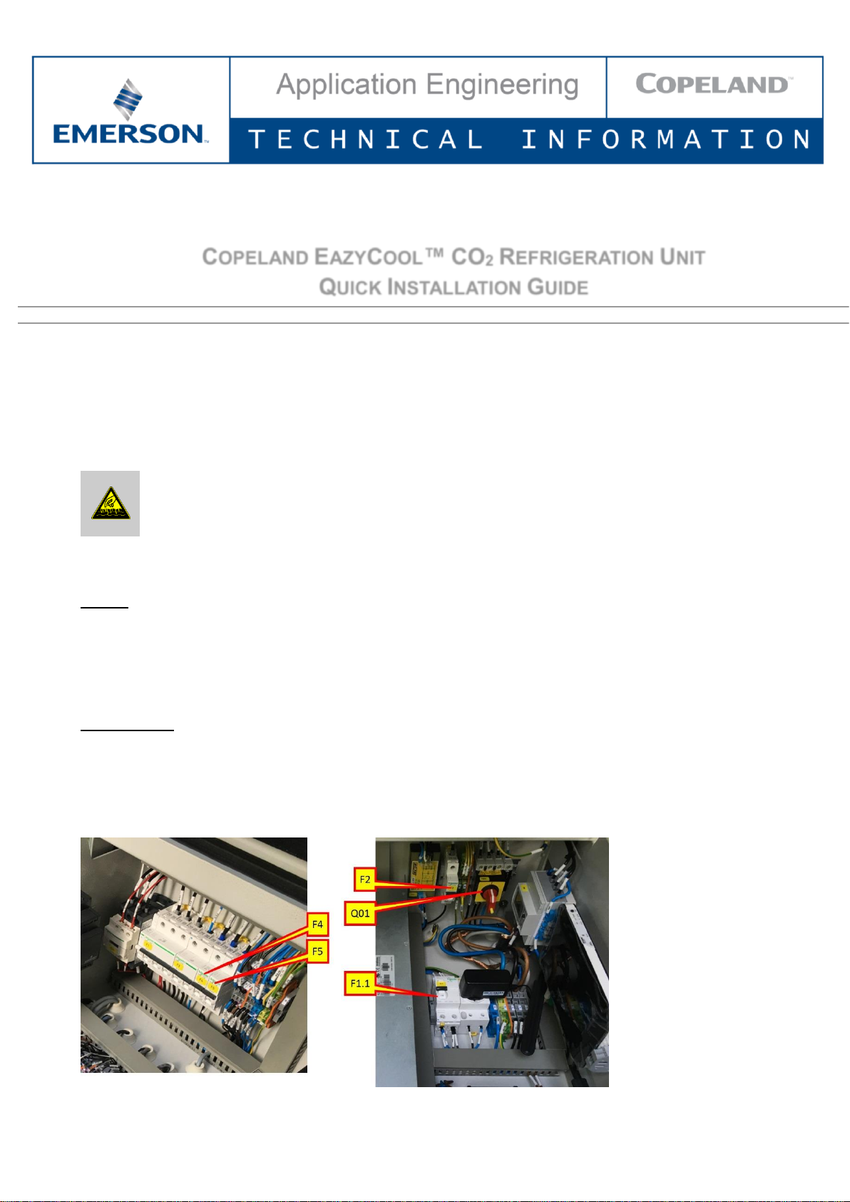
✓ Switch on the device main switch (Q01)
✓ Switch on the disconnector for the single-phase power supply (F2)
✓ Switch on the safety chain transformer isolator switch (F5)
✓ Switch on the disconnector for the crankcase heater (F4)
✓ Switch on the RCCB for online monitoring (F1.1 = power supply to the router), if available
Figure 1: Switch on control system & small electrical components
Page 2
CC7.8.9/0519/E 2/7
3 Pressure resistance test and leak test
CAUTION
The system must be properly evacuated before filling the cooling circuit with refrigerant.
This should result in a reduction of the residual moisture content to approx. 50 ppm.
Evacuation should be carried out to less than 3 mbar and, if necessary, the vacuum
should be broken with dried nitrogen.
Depending on the installation, pressure strength tests and leak tests must be carried out on different pressure
layers. The shut-off of system sections may be necessary.
Several shut-off devices are installed in the CO2 refrigeration unit. These are suction and pressure shut-off
valves of the compressor, high-pressure control valves at the gas cooler outlet, flash-gas bypass valves
between the liquid receiver and suction line, shut-off valves at the liquid receiver and shut-off valves in the
liquid line at the outlet from the refrigeration unit.
It is the responsibility of the user to decide which barriers are to be opened/closed in order to carry out the
pressure tests. For the evacuation process, it is recommended that all shut-off devices be opened and
evacuated from both sides via the connections on the suction side and the connection on the liquid receiver.
The shut-off valves at the discharge port, on the suction side of the compressor, at the outlet of the liquid
receiver and the shut-off valve in the liquid line can traditionally be operated manually.
To open the high-pressure control valve and the flash-gas control valve, please follow the instructions in
section 4 next page.
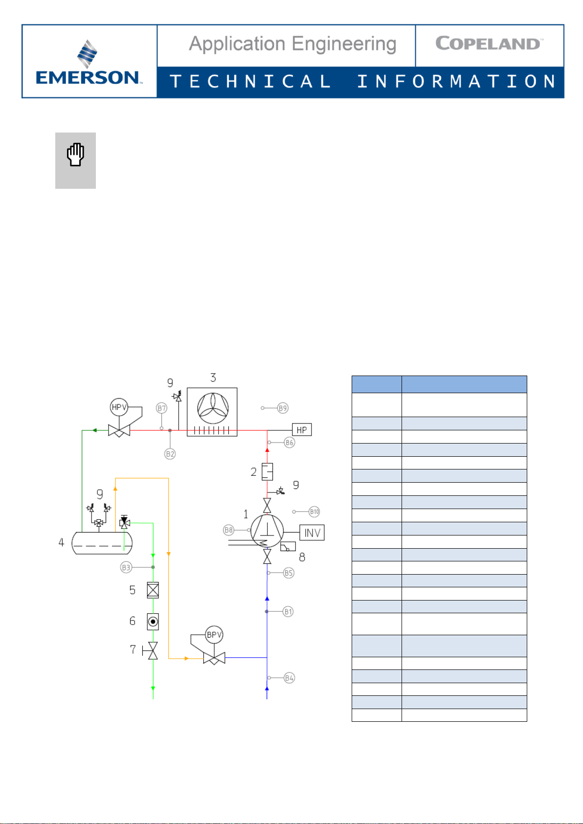
Figure 2: Shut-off valves in the CO2 refrigeration unit
Position
Description
1
Copeland Stream
compressor
2
Discharge mufler
3
Gas cooler/condenser
4
Flash tank
5
Filter-dryer
6
Sight glass
7
Ball valve
8
OW5 oil watch
9
Pressure relief valve
HPV
High pressure valve
BPV
Bypass valve
HP
High-pressure limiter
INV
Compressor inverter
B1
Suction pressure
B2
Discharge pressure
B3
Liquid receiver pressure
B4
Suction gas temperature
unit
B5
Suction gas temperature
compressor
B6
Discharge line temperature
B7
Gas cooler temperature
B8
Oil temperature
B9
Ambient temperature
B10
Cabinet temperature
Page 3
CC7.8.9/0519/E 3/7
4 Evacuation
IMPORTANT
The evacuation procedure is based upon achieving an actual system vacuum standard
and is NOT TIME DEPENDENT! The installation has to be evacuated with a vacuum
pump before commissioning. Proper evacuation reduces residual moisture to 50 ppm.
The installation of adequately sized access valves at the furthest point from the
compressor in the suction and liquid lines is advisable. The system must be evacuated
down to less than 3 mbar. If required break the vacuum with dry nitrogen. Pressure must
be measured using a vacuum pressure gauge on the access valves and not on the
vacuum pump. This serves to avoid incorrect measurements resulting from the pressure
gradient along the connecting lines to the pump.
IMPORTANT
Care must be taken that all components (solenoids, expansion devices, regulators, shut
off valves, etc…) in the refrigeration cycle, which separate a part of the installation when
de-energized, are manually opened to guarantee successful evacuation in the whole
piping system.
NOTE: The controller must be turned on before starting the evacuation.
NOTE: For proper evacuation, both the HPV and BPV regulating valves must be opened using the
evacuation mode in the unit controller.
To activate the evacuation mode:
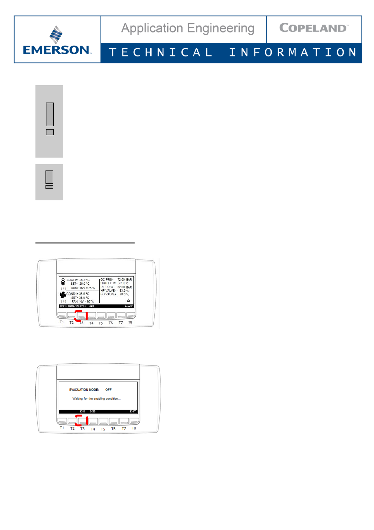
1) Press the SERVICE key to enter the "Service" menu
Figure 3: Service key
2) Use the UP and DOWN keys to select the "Evacuation mode" sub-menu
3) Press ENB to enable the evacuation mode (see Figure 4):
Figure 4
Page 4

CC7.8.9/0519/E 4/7
Starting the evacuation function:
The evacuation mode will start when pressing the ENB key only if all 3 of the following conditions are met:
▪ Suction pressure probe P1 value < SPF6
▪ Gas cooler (condenser) pressure probe P2 value < SPF6
▪ Flash tank pressure probe P3 value < SPF6
NOTE: SPF6 = Pressure setpoint to stop evacuation mode (factory-set to 10 bar).
The ENB key will remain visible all the time. If the evacuation function is enabled but one of the above
conditions is not met, the following message will be displayed:
▪ "Enabling condition for Evacuation Mode not met, waiting for it"
Subsequently:
1) The HP and BP valves open directly 100% (the evacuation mode has priority over the valves override
function).
2) The compressor is switched off (safety timers are ignored).
3) The fan is switched off, while auxiliary outputs are not influenced (safety timers are ignored).
4) The alarms are disabled except for the communication alarms.
Stopping the evacuation function:
The evacuation mode will be deactivated when
1) One of the 3 pressures probes P1, P2 & P3 > SPF6 or
2) the DISB key is pressed.
When the evacuation function is stopped, the controller returns to its previous status, ie, Off or regulation.
NOTE: As long as the evacuation function is active, the evacuation label will flash on the main display
– see Figure 5 below. After pressing the EXIT key, the previous screen will be displayed again.
Figure 5
NOTE: If one of the 3 probes (suction pressure, gas cooler pressure or flash tank pressure) is not
configured or in error, the evacuation mode cannot be executed.
Page 5

CC7.8.9/0519/E 5/7
5 Charging the CO2 refrigeration unit
CAUTION
High pressures! Risk of system damage! Only use pressure gauges that are suitable
for the required pressure positions. Check the connection hoses for suitability for CO2
pressure levels.
After leakage tests and evacuation have been performed, the system can be filled with R744 refrigerant. In
order to avoid the formation of dry ice, the system must be filled with gas on both sides first. Gaseous filling to
10 bar is common practice.
NOTE: Only pressure gauges and connection hoses suitable for high-pressure refrigerants can be
used.
Figure 6: Pressure gauges and connection hoses
After filling to approximately 10 bar on both sides, liquid CO2 can be filled into the liquid receiver. After
pressures in the refrigeration system and the CO2 tank have equalised, the missing refrigerant must be refilled
in gaseous form via the suction side.
For this purpose, the isolating switches for compressors (F1) and fans (F3) must be switched on and the
release for the frequency inverter (SB1) must be activated.
Figure 7: Enabling compressors, fans & frequency inverter
The refrigeration unit starts automatically. First the gas cooler fans start up, then the compressor switches on
and starts controlling according to suction pressure. The filling process via the suction side can be completed.
The system should be charged according to the liquid level in the bottom sight glass on the liquid receiver. As
soon as the bottom sight glass is completely charged with liquid CO2, a sufficient refrigerant charge is available.
The influence of the ambient temperature is negligible, as the pressure in the liquid receiver is regulated and
therefore the temperature in the receiver is constant. At low pressure in the refrigerant bottle, the evaporation
pressure "SETC1" can be set low to enable filling from the suction side.
During normal operation, the upper sight glass should not contain liquid refrigerant. Refrigerant in the upper
sight glass would be an indication of system overfilling. During pumpdown however, refrigerant may be present
in the upper sight glass.
Page 6

CC7.8.9/0519/E 6/7
6 Setting up the evaporating temperature
The CO2 refrigeration unit is controlled according to the suction pressure. The required evaporating
temperature can be set under parameter SETC1.
1) Press the PARAM key to access the programming menu
2) Use the UP and DOWN keys to select the Pr1 menu and press Pr1 to confirm
3) Select SETPOINT
4) Select setpoint "SETC1" using the SET key
5) Use the UP and DOWN keys to adjust SETC1 to the desired value
6) Press SET to apply the setting
7) Press EXIT to leave the menu
NOTE: The setpoint for the gas cooler fan is factory-set and should not be changed.
7 Setting up the liquid receiver pressure
1) Press the PARAM key to access the programming menu
2) Use the UP and DOWN keys to select the Pr1 menu and press Pr1 to confirm
3) Select GAS COOLER
4) Select parameter GC20 "Medium pressure vessel setpoint" using the SET key
5) Use the UP and DOWN keys to adjust GC20 to the desired value
6) Press SET to apply the setting
7) Press SET to select parameter GC78 "Bypass/medium pressure vessel pressure with compressor OFF"
8) Use the UP and DOWN keys to adjust GC78 to the desired value
9) Press SET to apply the setting
10) Press EXIT to leave the menu
GC20 "Medium pressure flashtank setpoint": Setpoint for the pressure in the liquid receiver in normal
control mode.
GC78 "Bypass/medium pressure vessel Pressure with compressor OFF": Maximum pressure in the liquid
receiver during standstill of the refrigeration unit. When this pressure is reached, the refrigeration unit starts to
maintain the medium pressure within an acceptable range, even if there is no cold demand from the cooling
stations.
8 Setting up pumpdown
If parameter SPF4 is set to "yes" a pumpdown will be performed before stopping the compressor. If it is set to
"no", only the manual pumpdown and the automatic pumpdown during the bypass optimization function will
be performed.
SPF1 Compressor setpoint during pumpdown
Range: -70°C to -10°C
Unit: [°C]
Parameter
Description
Level
Min value
Max value
Factory
setting
SPF1
Differential to be subtracted from
the compressor setpoint
Pr1
0K
20K
8K
SPF2
Compressor frequency during
pumpdown
Pr1
0%
(min speed
25 Hz)
100%
(max speed
60 Hz)
0%
SPF3
Pumpdown maximum time
Pr1
0 min
25 min
3 min
SPF4
Automatic pumpdown
Pr1
yes
SPF5
Pumpdown offset
Pr2
0°C
40°C
20°C
Table 1: Pumpdown parameters
Page 7

CC7.8.9/0519/E 7/7
The pumpdown function of the CO2 refrigeration unit does not work in the same way as in units using standard
refrigerants. Based on the ambient temperature and the compressor setpoint, the controller calculates two
different pumpdown setpoints:
▪ Setpoint based on ambient temperature = T
Amb
– SPF5
▪ Setpoint based on compressor setpoint = SETC1 – SPF1
The lowest pumpdown setpoint will always be applied. The following diagram illustrates the controller logic:
Figure 8: Controller logic for the pumpdown function
NOTE: The pumpdown setpoint will never be lower than what parameter RC02 allows.
-18°C < 0°C
Controller will perform
pumpdown down to -18°C
Ambient condition:
T
Amb
= 20°C
SPF5 = 20K
Compressor setpoint:
SETC1 = -10°C
SPF1 = 8K
Pumpdown setpoint based
on ambient temperature:
T
Amb
– SPF5 = 0°C
Pumpdown setpoint based on
compressor setpoint:
SETC1 – SPF1 = -18°C
 Loading...