

Emerson Copeland 71, Copeland 611, Copeland 121, Copeland 271, Copeland 65 Technical Information
...Page 1
Technical Information
Date of last update: Jul-05
Ref: CC7.5.1/0705/E
Application Engineering Europe
F
F
AANNSS FFOORR
C
C
OONNDDEENNSSIINNGG
U
U
NNIITTS
S
1 Introduction
Condensing units manufactured by Copeland are equipped with fan(s).
Various fan models are and were used.
That is to say that today, it is possible to meet various fan(s) on the after-sales market.
2 General information
Condensing units can be equipped with 1, 2 or 4 fans.
The complete fan consists of an external rotor motor with the fan blades permanently fixed to the rotor and the fan
guard. The grid has 4 feet to mount it on the condenser.
Fan motors are protected by a thermostatic switch. A single-pole bimetallic-element switch protects the motor
against damage from:
Motor overload
Over-voltage and under-voltage
Electrical and mechanical blockages
Inadequate cooling.
The fans protection is IP 54 and its insulation class is "F".
Most fans can be equipped with a speed controller connected to the condensing pressure.
3 Fans for Copeland Scroll and DWM Copeland semi-hermetic condensing units
The fan is positioned in order to blow the air from the condenser to the compressor, so the compressor additional
fan is not necessary any more.
NOTE: After connecting the condensing unit electrically, check the rotational direction. The fan must blow from
the condenser to the compressor.
NOTE: All fans presently used on condensing units are single-phase fans.
3.1 Single-phase fans
Single-phase fans are used since January 2003.
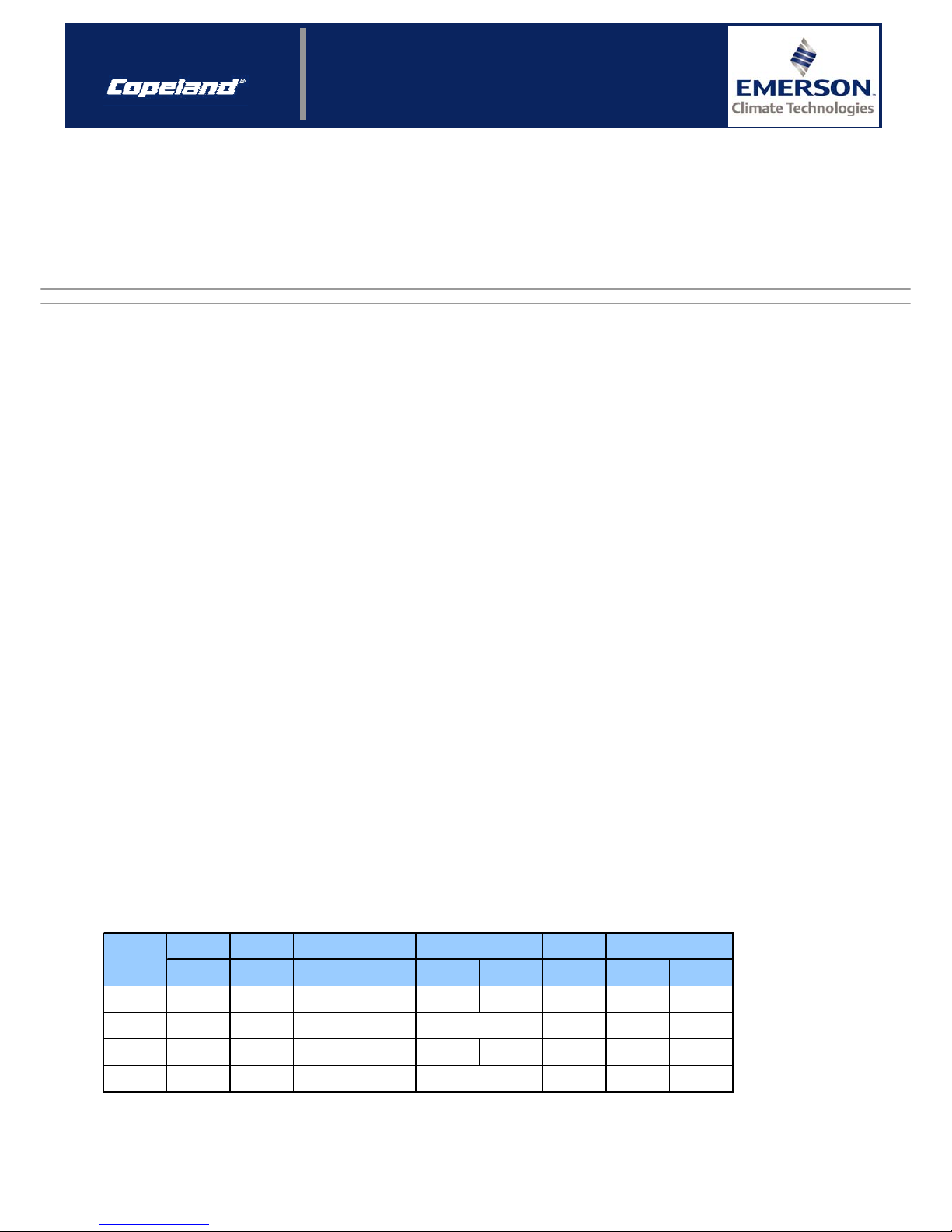
3.1.1 Technical data
As described in table 1, various fan models are used.
Blade
diamete
r
Power input Voltage
Motor
current
mm W V (±10%) / Ph / Hz EBM Rotomatika A Main Auxilary
71 300 95 220 - 240 / 1 / 50 3 / 400 2.5 / 400 0.44 115 129
121 350 117 220 - 240 / 1 / 50 0.54 72 108
271 420 300 220 - 240 / 1 / 50 5 / 400 6.3 / 400 1.35 25 88
611 500 570 220 - 240 / 1 / 50 2.4 8.5 20.5
10 / 400
Winding resistance
Ω
(±10%), 25°C
Run capacitor
µF / V
4 / 400
Fan model
Table 1: Technical data – single-phase fans
1/4
Page 2
CC7.5.1/0705/E
Technical Information
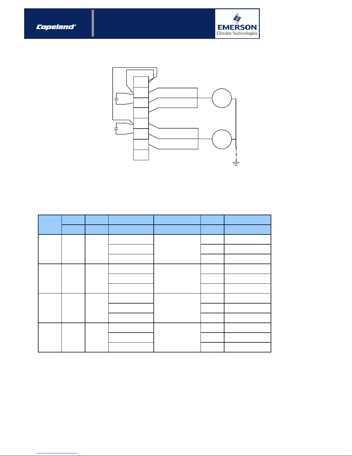
3.1.2 Single-phase fan wiring diagram
Z1 Black
U2 Blue
U1 Brown
M
1 ~
Z1 Black
U2 Blue
U1 Brown
M
1 ~
14
N
16
X1
15
13
L
9
10
11
L
C1
C1
12
Figure 1: Single-phase wiring diagram (230V ±15% / 1 ~ / 50-60 Hz)
3.2 Three-phase fans
Before January 2003, three-phase fans were used.
3.2.1 Technical data
Blade
diamete
r
Power input Voltage
Motor
current
mm W V (±10%) / Ph / Hz A
220 - 240 / 1 / 50 0.36
220-240 ∆ / 380-420 Y /
3 / 50
0.33 / 0.19
500 - 550 / 3 / 50 0.15
220 - 240 / 1 / 50 0.63
220-240 ∆ / 380-420 Y /
3 / 50
0.55 / 0.32
500 - 550 / 3 / 50 0.25
220 - 240 / 1 / 50 1.3
220-240 ∆ / 380-420 Y /
3 / 50
1.10 / 0.65
500 - 550 / 3 / 50 0.52
220 - 240 / 1 / 50 3.6
220-240 ∆ / 380-420 Y /
3 / 50
2.95 / 1.70
500 - 550 / 3 / 50 1.1
9.3
Winding resistance
5 / 400
8 / 400
16 / 400
25 / 400
20 / 60
51
6.2
6.2 / 18.6
54.7
57 ± 3 / 172 ± 10
325 ± 24
20
Ω (±10%), 25°C
102
104 ± 3 / 218 ± 6
574 ± 37
270 420 280
610 500 630
Fan model
75 300 80
Run capacitor
µF / V
120 350 135
Table 2: Technical data – three-phase fans
“Old” units were delivered with three-phase fans as a standard, but it is possible to convert these fans into singlephase motor by the mean of a capacitor. The characteristics of this run capacitor are given in table 2.
“New” single-phase kits can be used for retrofitting on units equipped with three-phase fans.
fan 75 is replaced by 71
fan 120 is replaced by 121
fan 210 is replaced by 211
fan 610 is replaced by 611
2/4
Page 3

CC7.5.1/0705/E
Technical Information
3.2.2 Three-phase fan wiring diagrams
14
15
16
13
11
12
10
U1 Brown
W1 Black
V2 Grey
U2 Red
W2 Orange
V1 Blue
U1 Brown
U2 Red
W1 Black
W2 Orange
V2 Grey
V1 Blue
X1
9
8
14
15
16
13
11
12
10
9
V2 Grey
V2 Grey
W1 Black
W1 Black
U2 Red
U2 Red
V1 Blue
V1 Blue
W2 Orange
W2 Orange
U1 Brown
U1 Brown
X1
8
A
=M21
L3
L2
L1
L3
L2
L1
A
=M21
L3
L2
L1
L3
L2
L1
A
=M22
A
=M22
Figure 2: ∆ 230V ±15% / 3 ~ / 50-60 Hz Figure 3: Y 400V±15% / 3 ~ / 50-60 Hz - Y 500V±15% / 3 ~ / 50-60 Hz
Three-phase fans can also be connected in single-phase thanks to a run capacitor.
V2 Grey
V2 Grey
W1 Black
W1 Black
U2 Red
U2 Red
V1 Blue
V1 Blue
W2 Orange
W2 Orange
U1 Brown
U1 Brown
White
White
White
White
C1
C1
M21
F10
M
Fan
M
Fan
M21
F10
15
16
X1
N
14
13
L
12
11
10
9
L
8
Figure 4: Three-phase fan converted to single-phase: ∆ 230V ±15% / 1 ~ / 50 Hz
F10
M21 … M22
M
Fan
A
White
White
n nn
6
M22
F10
X
1
7 8
M21
F10
X1 X
1
Figure 5: Fan motor protection = F10
3/4
Page 4

CC7.5.1/0705/E
Technical Information
3.3 Fans used on units manufactured before 1994
If you have an "old" unit manufactured before 1994, some fans are not supplied anymore, but you can replace them
with the present fans.
You can find the equivalent in the following cross reference (table 3).
Fan characteristics
Blade φ mm
Motor
Q2 Q3 350 25W 1 Ph still supplied
Q3 Q4 T42 T43 T81 350 60W 3 Ph model 120 / 121
Q5 Q6 Q7 T5 T71 T82 356 60W 3 Ph model 120 / 121
Q8 Q10 Q12 T93 T94 T101 T121 T151 420 200W 3 Ph model 270 / 271
T17 U61 U121 500 700W 3 Ph still supplied
Old condensor Replacement fan
Table 3: Cross-reference: replacement fans
4 Fans for Copeland EazyCool outdoor condensing units
The OM and OL units are fitted with a single-phase fan since the beginning of 2003, earlier manufactured units are
provided with a three-phase fan, models 120 and 270 depending on the condensing unit model.
Current used fans (model 121 or 271) are interchangeable with the previous models, but the wiring has to be
changed to single-phase wiring.
The OMQ and OLQ have a low speed (910 rpm) 6 pole single-phase motor.
Today, the condensers of the OM, OMQ, OL and OLQ units are equipped with single-phase fan(s).
The fan model is given in our Product Selection Catalogues and in Copeland Selection Software, both available on
www.eCopeland.com.
4.1 Technical data
Blade
diamete
r
Power input Voltage
Motor
current
mm W V (±10%) / Ph / Hz EBM Rotomatika A Main Auxilary
121 350 117 220 - 240 / 1 / 50 0.54 72 108
271 420 300 220 - 240 / 1 / 50 5 / 400 6.3 / 400 1.35 25 88
65 350 78 220 - 240 / 1 / 50 2 / 400 3.15 / 400 0.31 143 159
145 420 155 220 - 240 / 1 / 50 4 / 400 6.3 / 400 0.67 45.9 51.6
301 500 290 220 - 240 / 1 / 50 1.7 24.7 33.3
8 / 400
Run capacitor
µF / V
Winding resistance
Ω
(±10%), 25°C
Fan model
4 / 400
Table 4: Technical data – fans for Copeland EazyCool condensing units
4.2 Wiring diagram
See figure 1.
Information in this document are subject to change without notification.
4/4
 Loading...