

Page 1
Technical Specifications
December 2010
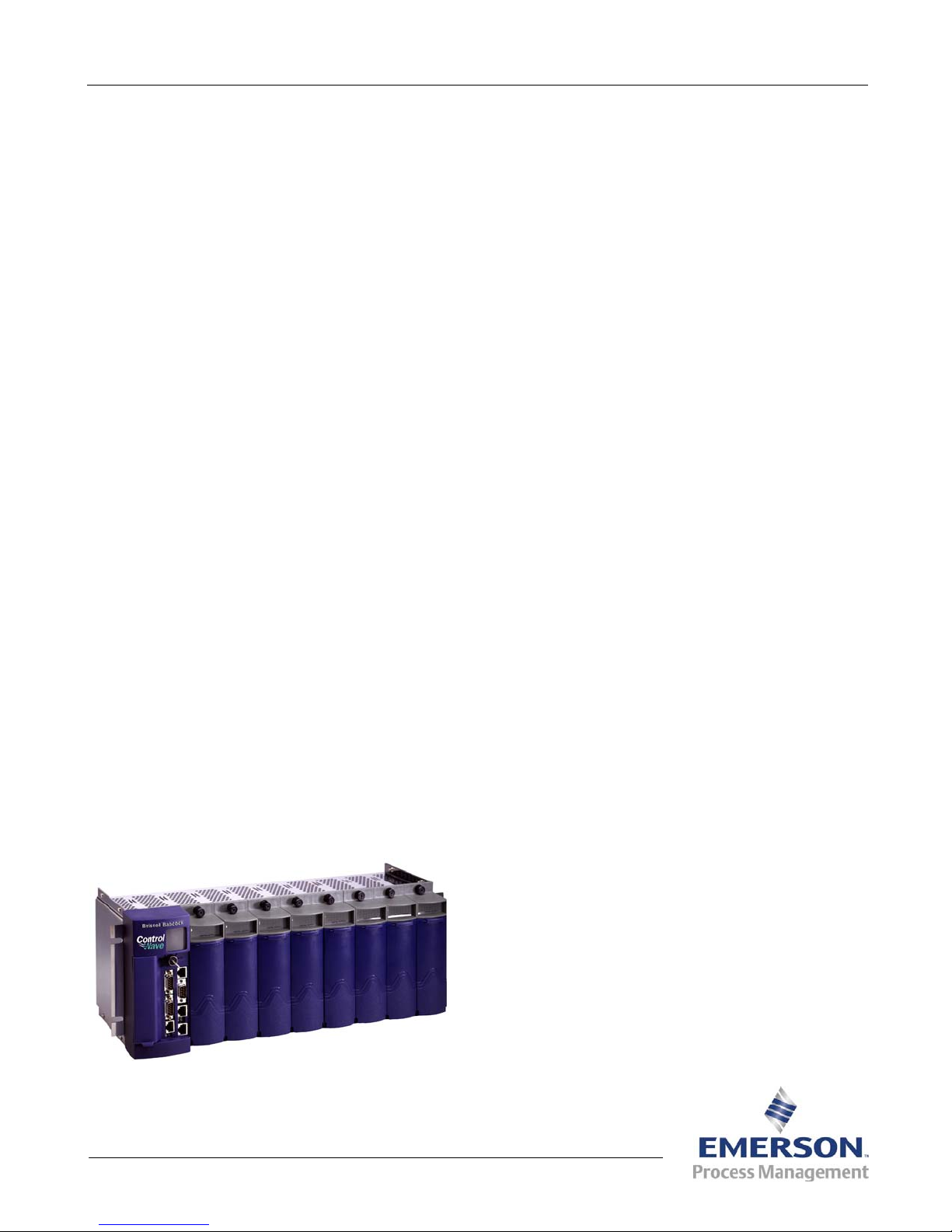
ControlWave® PAC
Process Automation Controller
CWPAC
The ControlWave® PAC is a highly adaptable
Process Automation Controller with exceptional
networking capability. Designed with an emphasis
on scalability and modularity, the ControlWave PAC
can be configured to maximize the performance of a
wide range of control systems. Emerson has
developed this innovative controller to provide costeffective solutions by minimizing the time required
for installation and configuration.
The ControlWave PAC combines the elements of a
PLC and an RTU without compromising the unique
features and capabilities of each device. The
ControlWave PAC provides a modular architecture,
expandable I/O capacity, and Ethernet networking
capability that introduces the possibilities of open
architecture for emerging communication standards
and provides a simple solution for existing networks.
Features
Powerful, high-performance processor
Up to three 10/100 MB Ethernet ports
Up to four serial communication ports
4- and 8-slot I/O base unit
Hot-swappable I/O
Security key-lock
Analog outputs maintain last/preset value on
CPU watchdog
Discrete outputs maintain last or zero value on
CPU watchdog
Wide temperature range (-40 to +70ºC)
Class I, Div. 2 hazardous location and CE
approval
Open industry standards for programming,
configuration, and communication
Base Unit
The ControlWave PAC base unit is constructed of a
stainless steel housing that contains the CPU,
power supply, and is available with a 4 or 8 I/O
slots. These slots are used to add optional I/O
modules.
CPU Options
The ControlWave PAC has a 100 MHz CPU module
that contains 2 MB of SRAM, 64 MB of SDRAM,
and 32 MB of flash memory. The CPU module is
available with the following on-board communication
port configurations:
One Ethernet port and two RS-232 ports
One Ethernet port, three RS-232 ports, and one
RS-485 port
Three Ethernet ports, three RS-232 ports, and
one RS-485 port
Three Ethernet ports, two RS-232 ports, and
two RS-485 ports
Power Modules
The power module is installed in the first slot of the
ControlWave PAC base unit and provides power to
the rest of the device. Two power modules are
available including:
24 volt input power supply sequencer module
24 volt redundant power supply sequencer
module
Open Network Connectivity
By embracing the open systems network
technologies available through TCP/IP, Ethernet,
OPC, and Microsoft DNA (as well as pseudo
standards such as Modbus and Open Modbus) the
ControlWave PAC provides a total process
automation management solution for in-plant
LAN-based and wide area network SCADA
systems. Access to real-time data and operating
conditions, historical data, maintenance, and
performance data stored in the ControlWave PAC is
available to the global network.
ControlWave PAC
Remote Automation Solutions
Website: www.EmersonProcess.com/Remote
D301303X012
Page 2

Technical Specifications
CWPAC
Page 2
Communications
The ControlWave PAC supports up to seven
communication ports. The base CPU module has
two RS-232 serial ports and one Ethernet port. Two
additional RS-232 or RS-485 serial ports and two
additional Ethernet ports are optional.
Communication Protocols
ControlWave PAC supports BSAP (Bristol Standard
Asynchronous Protocol), Modbus, DF1, CIP, DNP3,
and serial ASCII communication protocols as
standard features. ControlWave PAC also supports
the following Modbus protocols:
Modbus serial and TCP/IP Open Modbus
(Ethernet)
Master and Slave
Modbus RTU and ASCII
Function Codes 1–7, 8, 15, and 16
Integer and IEEE 4-byte floating point
Coils
Inputs and Outputs
Input and output (I/O) modules are designed to
maximize usability while minimizing installation,
maintenance, and system down-time costs. A pulldown door provides front panel wiring terminal
access for technicians. The bezel and the
terminations can be easily removed from the I/O
module to make wiring even easier. In addition, a
wide range of applications is supported by the
availability of both local terminations and remote
DIN-rail terminations.
To minimize field wiring and eliminate the need for
marshalling strips, the analog input (AI) and discrete
input (DI) modules are capable of supplying loop
power to two-wire transmitters and dry contacts.
Status indicators offer instant visual notification of
I/O conditions. Each I/O module has a two-color
Pass/Fail LED that displays the online diagnostic
status. Discrete I/O modules provide status LEDs
for each point on the module. AI modules provide
two LEDs on each input point to indicate input
under/over range conditions.
The ControlWave PAC supports a wide variety of
I/O modules. Available I/O modules include:
Analog Input (AI) module with 8 or 16 points
Analog Output (AO) module with 8 points
Discrete Input (DI) module with 16 or 32 points
Discrete Output (DO) module with 16 or 32
points
Resistance Temperature Detector (RTD)
module with 4 points
Thermocouple (TC) module with 6 points
UDI Counter module with 6 points
Note: Modules are hot-swappable. All I/O is frozen
for 300 milliseconds when any module is
replaced.
Remote Termination Modules
The remote termination option for the ControlWave
PAC modules provides a convenient alternative to
the standard direct connect termination. All remote
termination modules are standard DIN-rail
mountable, and connect to the I/O module with prewired connector cables. To simplify installation, all
I/O modules use the same cable.
I/O Expansion Rack
The I/O Expansion Rack allows for the addition of
I/O modules to multiple local and remote mounted
racks. The I/O Expansion Rack consists of a 4- or 8slot ControlWave chassis. This chassis contains an
Ethernet communication engine dedicated to
communications between the main processor and
the I/O Expansion Rack. The communication engine
also supports battery backed RAM to retain output
values during short power outages.
The I/O Expansion Rack is connected to the main
ControlWave via an Ethernet physical link using
TCP/IP. The process control application program
resides in the main ControlWave. The main
ControlWave controls both local I/O as well as the
I/O located in the I/O Expansion Rack.
ControlWave Redundant Systems
Redundant systems are ideal for use in critical
processes and harsh applications that require
maximum operational readiness and system
availability. The ControlWave PAC redundant
systems are designed to prevent a single point of
failure from shutting down the entire system. Two
types of redundant systems are available for the
ControlWave PAC: the redundant process control
and communications system, and the redundant
input/output (I/O) system. For more information on
the ControlWave PAC redundant systems, refer to
Technical Specifications CWPAC:RDN.
Key Switch
The ControlWave PAC is available with a threeposition front panel key switch. The front panel key
switch provides a high level of manual security by
controlling three modes of operation.
In Run Mode, the ControlWave PAC rejects any
attempt to download or modify the running program,
either locally or over the network.
Page 3

Technical Specifications
CWPAC
Page 3
In Remote Mode, the ControlWave PAC allows
downloading and online program modification
through the network provided the security access
requirements have been met. Local download and
online modification of the running program is
prohibited.
In Local Mode, the ControlWave PAC allows
download and online modification through either the
network connection or through a local serial
communication port provided the security access
requirements have been met.
Multi-User Security Access
The ControlWave PAC employs a user
name/password access system protected by a
56-bit encryption technique through the TCP
connection. There can be up to 240 users who sign
in with their user name and password. Both the user
name and the password can be up to sixteen
characters in length.
You can customize the security level for each user
based on 64 access rights including the ability to
read and write data values and files via FTP, access
and configure historical and audit data information,
edit configuration, run internal diagnostics, and read
and reset system status.
Data Reliability
The ControlWave PAC is designed to provide the
optimum level of data reliability using a distributed
database architecture. All data, including time
stamped alarms, alarm limits, and historical data is
stored locally in non-volatile flash memory in each
ControlWave PAC.
When historical data is collected from the
ControlWave PAC, it is converted and appended to
a .CSV and ODBC compliant database. The original
historical data is not changed and is stored in the
device flash memory.
Historical Data Collection
The ControlWave Historical Data Collection system
provides time-stamped historical data storage in
ControlWave flash memory. The historical data is
collected through OpenBSI software on a scheduled
or on-demand basis. After the data is collected, it is
converted to CSV and ODBC compliant file formats
for use in spreadsheets and reports. If any data is
missed due to a communication failure, it is
collected and the PC historical database is
backfilled when the communication is reestablished.
This distributed historical database architecture
provides data reliability and integrity during
communication or PC failure.
Another important historical feature is the audit
system. The audit logs are files stored in
ControlWave flash memory that contain significant
events and time-stamped alarms. In addition to the
real-time alarm reporting system, the alarms stored
in the audit alarm log provide a reportable historical
alarm archive.
Theses files are collected through OpenBSI
software and presented as text files in the PC. This
functionality is extremely useful in providing an
event trail during communication interruption, PC
downtime, or other system problem.
OpenBSI
Emerson’s OpenBSI (Open Bristol System
Interface) is an optional set of network setup,
communication, diagnostic, and data viewing
software utilities for use with ControlWave RTUs,
flow computers, and controllers. At the core of
OpenBSI is the communication interface. The
interface is written as a Windows communication
server API through which other client applications
communicate. OpenBSI supports both serial BSAP
protocol and Ethernet IP communication to
ControlWave devices.
ControlWave Designer
ControlWave Designer is an optional, fully IEC
61131-3 compliant programming environment for
the ControlWave PAC. ControlWave Designer
includes all five IEC 61131-3 process languages for
batch, continuous, and discrete control. These
languages are: Function Block Diagram, Structured
Text, Sequential Function Chart, Ladder Logic
Diagram, and Instruction List.
ControlWave Designer includes an extensive library
of more than 200 basic IEC 61131-3 functions and
function blocks common to many IEC 61131-3
based products. These include:
Flip-flops, counters, and timers
Ladder diagram functions – coils and contacts,
etc.
Numerical, arithmetic, and Boolean functions –
Sine, Cosine, Add, Sub, Square Root, And, Or,
etc.
Selection and comparison – Min, Max, Greater
Than, Equal, Less Than, etc.
Type conversions – Integer to Real, Boolean to
Word, etc.
Page 4

CWPAC
Technical Specifications Page 4
ACCOL III
In addition to the basic functions and function
blocks, ControlWave Designer brings the benefit of
over twenty years of SCADA and plant control
experience in Emerson’s ACCOL III function block
library. ACCOL III includes over sixty function blocks
valuable for use in oil and gas, water and waste,
and process measurement and control applications.
ACCOL III is designed to take full advantage of the
significant features offered by ControlWave.
The library consists of many function blocks
including:
ObjectServer
ObjectServer is an optional OPC-compliant server
that provides direct communication to the
ControlWave family of controllers, RTUs, PLCs, and
flow computers through the OpenBSI
Communications Interface. ObjectServer supports
serial multi-drop, remote telemetry, and Ethernet
communication networks. Unlike traditional OPC
servers, ObjectServer provides reliable access to
RTUs that are connected via low-bandwidth, highlatency, and poor-quality networks such as radio,
satellite, and cellular modems.
Average, Compare, Totalize
Scheduling and Sequencing
PID and Lead/Lag
AGA Gas Flow and Liquids Calculations
File Handling
NIST-23
ControlWave PAC
CPU Module
Processor Type 586 CPU, 100 MHz
Memory Boot 512 kB
Flash 32 MB on-board
SRAM 2 MB, battery backed
SDRAM 64 MB (66MHz SDRAM coupled to a 32-bit bus)
Clock Accuracy 2 second/day at 25˚C
Communications
COM1 Type RS-232
Connector PC/AT 9-pin male D-sub
Baud Up to 115.2 KB
COM2 Type RS-232
Connector PC/AT 9-pin male D-sub
Baud Up to 115.2 KB
COM3 (optional) Type RS 232 or RS 485
Connector RJ45
Baud Up to 115.2 KB
Isolation 500 Vdc (RS-485 only)
COM4 (optional) Type RS-485
Connector PC/AT 9-pin male D-sub
Isolation 500 Vdc
Ethernet Port 1 Type 10/100 Base-T Ethernet port
Connector RJ45
Isolation 500 Vdc
Page 5

CWPAC
Technical Specifications
Page 5
Ethernet Port 2 (optional) Type 10/100 Base-T Ethernet port
Connector RJ45
Isolation 500 Vdc
Ethernet Port 3 (optional) Type 10/100 Base-T Ethernet port
Connector RJ45
Isolation 500 Vdc
Inputs/Outputs
Surge Protection Surge protection meets IEEE C37.90-1978 and IEC 801-5.
Note: Surge protection applies to all I/O modules.
Analog Input Module Quantity 8 or 16
Type Internally or externally sourced, single-ended, 4–20 mA inputs
Connector Terminal block or remote termination
Resolution 14-bit
Isolated Voltage
Input
Externally
Voltage Input Isolated differential inputs 1–5 Vdc
Current Input Externally sourced current loop with 1–5 V input module and 250 ohm
Input Impedance > 1 megOhm for 1–5 Vdc, 250 Ohm for 4–20 mA
Common Mode
Rejection
Normal Mode
Rejection
Input Filtering 300 milliseconds to 99.9% of input signal
Channel Settling
Time
Conversion Time 25 microseconds
Accuracy 0.1% of span 25˚C
Isolated Voltage
Common Mode
Range
Status Indicator Normal, Over-range/Under-range, FAIL and OK module status LEDs
Surge
Supression
Internally
Sourced
Sourced
resistor across the input terminals or 4–20 mA input module. On-board
isolated loop power supply for internally powered AI.
70 db
26 db
680 microseconds
0.2% of span –20˚C to 70˚C
0.3% of span –40˚C to 70˚C
31 Vdc to isolated common
500 Vdc MOV isolated common to chassis.
31 Vdc transorb across input signals and negative input to chassis
500 Vdc per module to chassis
31 Vdc per channel
Page 6

Technical Specifications
CWPAC
Page 6
Analog Output Module
with Read-Back
(for redundant I/O
systems only)
Resolution 12-bit
Output Accuracy 0.2% of span at 25˚C for current output
Settling Time 1 millisecond
Status Indicator FAIL and OK module status LEDs
Surge
Analog Output Module Quantity 4 or 8
Output
Connector Terminal block or remote termination
Resolution 12-bit
Accuracy 0.1% of span @ 25˚C for current output
Settling Time 1 millisecond
Status Indicator
Surge
Fail Safe Configurable Output Fail State (hold last value, zero (–5%), to specified
Digital Input Module Quantity 16 or 32 non-interrupting inputs
Type Selectable internally or externally powered dry contact
Connector Terminal block or remote termination
Voltage Range 24 Vdc nominal
Input Current 5 mA nominal
Optical Isolation 1500 Vdc field input to logic
Surge
Input Filtering 30 milliseconds time constant (contact bounce)
Status Indication LED per point status and module OK/FAIL LED
Quantity 8
Output
Configurations
Connector Terminal block or remote termination
Suppression
Configurations
Suppression
Suppression
4–20 mA (650 max. drive)
0.35% of span at –20 to 70˚C for current output
0.5% of span at –40 to 70˚C for current output
500 Vdc MOV isolated common to chassis
31 Vdc transorb across output signals and negative output to common
4–20 mA (650 max. drive)
0.2% of span @ –20 to 70˚C for current output
0.3% of span @ –40 to 70˚C for current output
FAIL and OK module status LED
500 Vdc MOV isolated common to chassis
31 Vdc transorb across output signals and negative output to common
value)
21 Vdc internal loop supply
500 Vdc MOV to chassis
31 Vdc transorb between signal and isolated ground
Page 7

Technical Specifications
CWPAC
Page 7
Digital Output Module with
Read-Back
(for redundant I/O
systems only)
Voltage Range 10–31 Vdc
Maximum
Current Sink
Electrical
Surge
Status Indicator LED per point status and module OK/FAIL LED
Fail Safe Configurable as Fail State OFF or Hold Last Value
Digital Output Module Quantity 16 or 32
Type Solid-state open source MOSFET
Connector Terminal block or remote termination
Voltage Range 10–31 Vdc
Maximum
Current Sink
Electrical
Surge
Status Indicator LED per point status and module OK/FAIL LED
Fail Safe Configurable as Fail State OFF or Hold Last Value
RTD Input Module Quantity 4
Type 2, 3, or 4 wire RTD
Connector Terminal block or remote termination
Resolution 16-bit
Voltage Input
Channel Data
Conversion Time 3-wire: 266 milliseconds
Input Accuracy +/– 0.5°C at 25°C
Common Mode
Quantity 16
Type Solid-state open source MOSFET
Connector Terminal block or remote termination
20 Hz
Operating
Frequency
500 mA at 31 Vdc
Load Capability
1500 Vdc
Isolation
500 MOV to chassis.
Suppression
Operating
Frequency
Load Capability
Isolation
Suppression
Impedance
Acquisition
Rejection
31 Vdc transorb between signal and isolated ground
20 Hz
500 mA at 31 Vdc
1500 Vdc
500 MOV to chassis
31 Vdc transorb between signal and isolated ground
9.6 kOhm
50 microseconds
4-wire: 200 milliseconds for all 4 inputs
+/– 1.0°C at –40°C to 70°C
120 db
Page 8

Technical Specifications
CWPAC
Page 8
RTD Input Module
(continued)
Electrical
Surge
Status Indicator Normal, Over/Under Range, and module OK/FAIL LEDs
Thermocouple Input
Module
Type B, R, S, J, E, K, T, C, N, +/– 10 mV
Connector Terminal block or remote termination
Resolution 16-bit
Input
Voltage Input
Channel Data
Conversion Time 66 milliseconds for all six inputs
Input Accuracy Varies by thermocouple type:
Common Mode
Normal Mode
Electrical
Surge
Status Indicator Normal, Over/Under Range, and module OK/FAIL LEDs
Cold Junction
Module and Counter (UDI)
Connector Terminal block or remote termination
Bus Access 16-bits wide
Frequency
Input Voltage
Debounce User-selectable debounce circuitry
Input Current 5 mA +/– 10%
Normal Mode
Rejection
Isolation
Suppression
Quantity 6
Configuration
Impedance
Acquisition
Rejection
Rejection
Isolation
Suppression
Compensation
Quantity 6 or 12 Universal Digital Input
Type Polled DI and High-Speed Counter or Low-Speed Counter
Range
Range
80 db
500 Vdc channel to channel and channel to bus
12 Vdc transorb between signal and ground
Differential thermocouple
10 megOhm
50 microseconds
0.025% of span at 25°C for 10 mV input
0.05% of span –25°C to 70°C for 10 mV input
120 db
80 db
500 Vdc channel to channel and channel to bus
180 Vdc transorb between signal and ground
RTD sensor on terminal block
Internally or externally sourced 24 Vdc
0–10 KHz
24 Vdc
Page 9

CWPAC
Technical Specifications Page 9
Universal Digital Input
Module and Counter
(continued)
Electrical
Surge
Status Indicator LED per point status and module OK/FAIL LED
Status Indication Status LED per input, module PASS/FAIL LED
Input Filtering Software configurable
20 microseconds for high speed counter
1 millisecond for low speed counter
30 milliseconds for contact closure interruptible DI
1500 Vdc to system logic and 500 Vdc to chassis
Isolation
31 Vdc transorb across input and to field common
Suppression
Power
Input Voltage Range 22.1–30.0 Vdc
Isolation 500 Vdc
Status Indication Active , Fail, and Power OK
Physical
Dimensions 4 I/O Slot
Chassis
8 I/O Slot
Chassis
Weight 4 I/O Slot
Chassis
8 I/O Slot
Chassis
Wiring Up to 14 American Wire Gauge (AWG)
Panel Mount 300.73 mm W by 177.03 mm H by 125.98 mm D
(11.84 in. W by 6.97 in. H by 4.96 in. D)
Panel Mount or
19 Inch Rack
Mount
3.18 kg (7 lbs.)
5.9 kg (13 lbs.)
481.58 mm W by 177.03 mm H by 125.98 mm D
(18.96 in. W by 6.97 in. H by 4.96 in. D)
Environmental
Operating Temperature –40 to 70ºC (–40 to 158ºF)
Storage Temperature –40 to 85ºC (–40 to 185ºF)
Operating Humidity 15 to 95% (non-condensing)
Vibration 1.0 g acceleration over 10–150 Hz; 0.5 g acceleration over 150–2000 Hz
Immunity 3 V/m – 80 MHz to 1000Mhz (EN50082-2)
Electro-Static Discharge IEC-1000-4-2-EVT
Radiated Emissions EN-55011-EVT
Surge Suppression IEEE 472 - 1974
Page 10

Technical Specifications
Page 10
Approvals
UL CUL
Hazardous Locations
CE
Certification Standard UL Standards UL 1604-1994
EMC Standards EN 55011 (Emissions)
Class I, Division 2, Groups A, B, C, and D T4A Product Markings for
0081
UL 508-2008
CSA C22.2 No. 213-M1987
CSA C22.2 No. 142-M1987
EN 61000-4-2 (Electrostatic Discharge Immunity)
EN 61000-4-3 (Electromagnetic Field Immunity)
EN 61000-4-4 (Electrical Fast Transients Immunity)
EN 61000-4-5 (Surge Immunity)
EN 61000-4-6 (Conducted Immunity)
CWPAC
Bristol, Inc., Bristol Canada, BBI SA de CV and Emerson Process Management Ltd, Remote Automation Solutions division (UK), are wholly
owned subsidiaries of Emerson Electric Co. doing business as Remote Automation Solutions (“RAS”), a division of Emerson Process
Management. FloBoss, ROCLINK, Bristol, Bristol Babcock, ControlWave, TeleFlow and Helicoid are trademarks of RAS. AMS, PlantWeb and
the PlantWeb logo are marks of Emerson Electric Co. The Emerson logo is a trademark and service mark of the Emerson Electric Co. All
other marks are property of their respective owners.
The contents of this publication are presented for informational purposes only. While every effort has been made to ensure informational
accuracy, they are not to be construed as warranties or guarantees, express or implied, regarding the products or services described herein
or their use or applicability. RAS reserves the right to modify or improve the designs or specifications of such products at any time without
notice. All sales are governed by RAS’ terms and conditions which are available upon request. RAS does not assume responsibility for the
selection, use or maintenance of any product. Responsibility for proper selection, use and maintenance of any RAS product remains solely
with the purchaser and end-user.
Emerson Process Management
Remote Automation Solutions
Watertown, CT 06795 U.S.A.
Mississauga, ON 06795 Canada
Worcester WR3 8YB UK
© 2007–2010 Remote Automation Solutions, division of Emerson Process Management. All rights reserved.
 Loading...