

Page 1
Instruction Manual
s
Document: CI-ControlWave
Part: D301381X012
November 2010
ControlWave Process Automation
Controller
ControlWave
Remote Automation Solution
www.EmersonProcess.com/Remote
Page 2

Be sure that these instructions are carefully read and understood before any operation is
attempted. Improper use of this device in some applications may result in damage or injury. The
user is urged to keep this book filed in a convenient location for future reference.
These instructions may not cover all details or variations in equipment or cover every possible
situation to be met in connection with installation, operation or maintenance. Should problems arise
that are not covered sufficiently in the text, the purchaser is advised to contact Emerson Process
Management, Remote Automation Solutions division (RAS) for further information.
IMPORTANT! READ INSTRUCTIONS BEFORE STARTING!
EQUIPMENT APPLICATION WARNING
The customer should note that a failure of this instrument or system, for whatever reason, may
leave an operating process without protection. Depending upon the application, this could result in
possible damage to property or injury to persons. It is suggested that the purchaser review the
need for additional backup equipment or provide alternate means of protection such as alarm
devices, output limiting, fail-safe valves, relief valves, emergency shutoffs, emergency switches,
etc. If additional information is required, the purchaser is advised to contact RAS.
RETURNED EQUIPMENT WARNING
When returning any equipment to RAS for repairs or evaluation, please note the following: The
party sending such materials is responsible to ensure that the materials returned to RAS are clean
to safe levels, as such levels are defined and/or determined by applicable federal, state and/or
local law regulations or codes. Such party agrees to indemnify RAS and save RAS harmless from
any liability or damage which RAS may incur or suffer due to such party's failure to so act.
ELECTRICAL GROUNDING
Metal enclosures and exposed metal parts of electrical instruments must be gr ounded in
accordance with OSHA rules and regulations pertaining to "Design Safety Standards for Electrical
Systems," 29 CFR, Part 1910, Subpart S, dated: April 16, 1981 (OSHA rulings are in agreement
with the National Electrical Code).
The grounding requirement is also applicable to mechanical or pneumatic instruments that
include electrically operated devices such as lights, switches, relays, alarms, or chart drives.
EQUIPMENT DAMAGE FROM ELECTROSTATIC DISCHARGE VOLTAGE
This product contains sensitive electronic components that can be damaged by exposure to an
electrostatic discharge (ESD) voltage. Depending on the magnitude and duration of the ESD, this
can result in erratic operation or complete failure of the equipment. Read supplemental document
S14006 for proper care and handling of ESD-sensitive components.
Remote Automation Solutions
A Division of Emerson Process Management
1100 Buckingham Street, Watertown, CT 06795
Telephone (860) 945-2200
Page 3
Emerson Process Management
Training
GET THE MOST FROM YOUR EMERSON
INSTRUMENT OR SYSTEM
Avoid Delays and problems in getting your system on-line
Minimize installation, start-up and maintenance costs.
Make the most effective use of our hardware and software.
Know your system.
As you know, a well-trained staff is essential to your operation. Emerson offers a full
schedule of classes conducted by full-time, professional instructors. Classes are offered
throughout the year at various locations. By participating in our training, your personnel
can learn how to install, calibrate, configure, program and maintain your Emerson products
and realize the full potential of your system.
For information or to enroll in any class, go to http://www.EmersonProcess.com/Remote
click on “Educational Services” or contact our training department in Watertown at (860)
945-2200.
and
Page 4

This page is intentionally left blank
Page 5

ControlWave Instruction Manual (CI-ControlWave)
Contents
Chapter 1 – Introduction 1-1
1.1 Scope of the Manual.................................................................................................................1-2
1.2 Physical Description..................................................................................................................1-2
1.3 Housings ...................................................................................................................................1-3
1.4 CPU Module..............................................................................................................................1-5
1.5 Power Supply/Sequencer Module (PSSM)...............................................................................1-7
1.6 I/O Modules...............................................................................................................................1-7
1.7 Software Tools ..........................................................................................................................1-8
Chapter 2 – Installation 2-1
2.1 Site Considerations...................................................................................................................2-1
2.1.1 Class I, Div 2 Installation Considerations......................................................................2-2
2.2 Installation Overview.................................................................................................................2-2
2.2.1 Unpacking Components................................................................................................2-3
2.2.2 Color Coding of Slot Connectors ..................................................................................2-4
2.2.3 Mounting the Housing...................................................................................................2-4
2.2.4 Grounding the Housing.................................................................................................2-6
2.3 Power Supply/Sequencer Module (PSSM)...............................................................................2-7
2.3.1 General Information about the PSSM...........................................................................2-9
2.3.2 PSSM Installation Overview..........................................................................................2-9
2.3.3 General Wiring Guidelines..........................................................................................2-10
2.3.4 Wiring a Bulk DC Power Supply to the PSSM............................................................2-10
2.3.5 Wiring an External Alarm or Annunciator to the Watchdog Connector and Wiring the
Redundancy Control Input (OPTIONAL)................................................................................2-15
2.4 CPU Module............................................................................................................................2-18
2.4.1 Setting DIP Switches on the CPU Module..................................................................2-19
2.4.2 Connections to RS-232 Serial Port(s).........................................................................2-22
2.4.3 Connections to RS-485 Serial Port(s) on Secondary Communication Board (SCB)..2-27
2.4.4 Connections to Ethernet Port(s) on the CPU Module.................................................2-29
2.5 Bezels......................................................................................................................................2-30
Chapter 3 – I/O Modules 3-1
3.1 Module Placement ....................................................................................................................3-3
3.2 Status LEDs ..............................................................................................................................3-4
3.3 Wiring........................................................................................................................................3-4
3.2.1 Local Termination..........................................................................................................3-5
3.2.2 Remote Termination......................................................................................................3-6
3.2.3 Shielding and Grounding...............................................................................................3-6
3.4 Digital Input (DI) Modules..........................................................................................................3-8
3.5 Digital Output (DO) Modules...................................................................................................3-13
3.6 Analog Input (AI) Modules.......................................................................................................3-19
3.7 Analog Output (AO) Modules..................................................................................................3-24
3.8 Universal Digital Input (UDI) Modules.....................................................................................3-29
3.9 Isolated Resistance Temperature Device (RTD) Input Module..............................................3-35
3.10 Isolated Low Level Analog Input (LLAI) Module .....................................................................3-39
Chapter 4 – Operation 4-1
4.1 Powering Up/Powering Down the ControlWave .......................................................................4-1
Issued Nov-2010 Contents v
Page 6

ControlWave Instruction Manual (CI-ControlWave)
4.2 Setting the Operating Mode (Run/Remote/Local Switch).........................................................4-1
4.3 Communicating with the ControlWave......................................................................................4-2
4.3.1 Default Comm Port Settings .........................................................................................4-2
4.3.2 Collecting Data from the ControlWave..........................................................................4-3
4.4 Creating and Downloading an Application (ControlWave Project)...........................................4-3
4.5 Creating and Maintaining Backups...........................................................................................4-4
4.5.1 Creating a Zipped Project File (*.ZWT) For Backup.....................................................4-5
4.5.2 Saving Flash Configuration Parameters (*.FCP)..........................................................4-6
4.5.3 Backing up Data............................................................................................................4-8
Chapter 5 – Service and Troubleshooting 5-1
5.1 Upgrading Firmware..................................................................................................................5-2
5.2 Removing or Replacing Components.......................................................................................5-5
5.2.1 Accessing Modules for Testing.....................................................................................5-5
5.2.2 Removing/Replacing the Bezel.....................................................................................5-5
5.2.3 Removing/Replacing the CPU Module.........................................................................5-6
5.2.4 Removing/Replacing the PSSM....................................................................................5-6
5.2.5 Removing/Replacing an I/O Module (Hot Swapping)...................................................5-7
5.2.6 Removing/Replacing the Backup Battery...................................................................5-12
5.3 General Troubleshooting Procedures.....................................................................................5-12
5.3.1 Checking LEDs ...........................................................................................................5-13
5.3.2 Checking Wiring/Signals.............................................................................................5-21
5.3.3 Port 80 Display Codes ................................................................................................5-22
5.3.4 Reset Switch...............................................................................................................5-25
5.4 WINDIAG Diagnostic Utility.....................................................................................................5-25
5.4.1 Available Diagnostics..................................................................................................5-28
5.5 Core Updump..........................................................................................................................5-32
Appendix A – Special Instructions for Class I, Division 2 Hazardous Locations A-1
Appendix P - Redundant Power Supply Sequencer Module (RPSSM) P-1
Appendix Z – Sources for Obtaining Material Safety Data Sheets (MSDS) Z-1
Index IND-1
vi Contents Issued Nov-2010
Page 7

Chapter 1 – Introduction
This manual focuses on the hardware aspects of the ControlWave
Process Automation Controller (called the “ControlWave” throughout
the rest of this manual). For information about the software used with
the ControlWave, refer to the ControlWave Quick Setup Guide (D5084),
the ControlWave Designer Programmer’s Handbook (D5125), and the
online help in ControlWave Designer.
This chapter details the structure of this manual and provides an
overview of the ControlWave and its components.
In This Chapter
1.1 ........................................................................1-2 Scope of the Manual
........................................................................1-2 Physical Description
1.2
..........................................................................................1-3 Housings
1.3
....................................................................................1-5 CPU Module
1.4
.....................................1-7 Power Supply/Sequencer Module (PSSM)
1.5
......................................................................................1-7 I/O Modules
1.6
.................................................................................1-8 Software Tools
1.7
ControlWave Instruction Manual (CI-ControlWave)
Features
ControlWave products have been designed and integrated as a highly
adaptable, high performance distributed open controller family with
exceptional networking capability that provides a complete process
automation management solution for the natural gas, water, and
wastewater industries. The ControlWave was designed with an
emphasis on providing high performance with low power consumption,
scalability, and modularity.
ControlWave process automation controllers have the following key
features:
Low power consumption
Wide operating temperature range: (–40 to +70C) (–40 to 158F)
Small size (enabling panel mount or 19 inch rack-mount
installations)
Two RS-232 ports
One 10/100 MB Ethernet port
Optional secondary communication board (SCB) provides additional
options for RS-232, RS-485, and Ethernet communications
Housings to support four or eight I/O modules
Variety of I/O modules and support for hot swapping of I/O modules
Support for redundant operation with another ControlWave process
automation controller
LED status indicators on the CPU, PSSM, and certain I/O modules
Port 80 display to present status codes
Revised Nov-2010 Introduction 1-1
Page 8
ControlWave Instruction Manual (CI-ControlWave)
Battery backup for the real-time clock and the system’s static RAM
(SRAM)
Class I, Division 2 Hazardous Location approvals
1.1 Scope of the Manual
This manual contains the following chapters:
Chapter 1
Introduction
Chapter 2
Installation
Chapter 3
I/O Modules
Chapter 4
Operation
Chapter 5 Service and
Troubleshooting
1.2 Physical Description
Each ControlWave has a printed circuit board (PCB) backplane
mounted in a stainless steel housing, a Power Supply/Sequencer Module
(PSSM), a CPU module which may include an optional Secondary
Communication Board (SCB) and—depending on the backplane and
housing size—up to eight I/O modules.
Provides an overview of the hardware and
general specifications for the ControlWave.
Provides information on the housings, the
Power Supply/Sequencer module (PSSM), and
the CPU module.
Provides general information and wiring
diagrams for the I/O modules.
Provides information on day-to-day operation of
the ControlWave.
Provides information on service and
troubleshooting procedures.
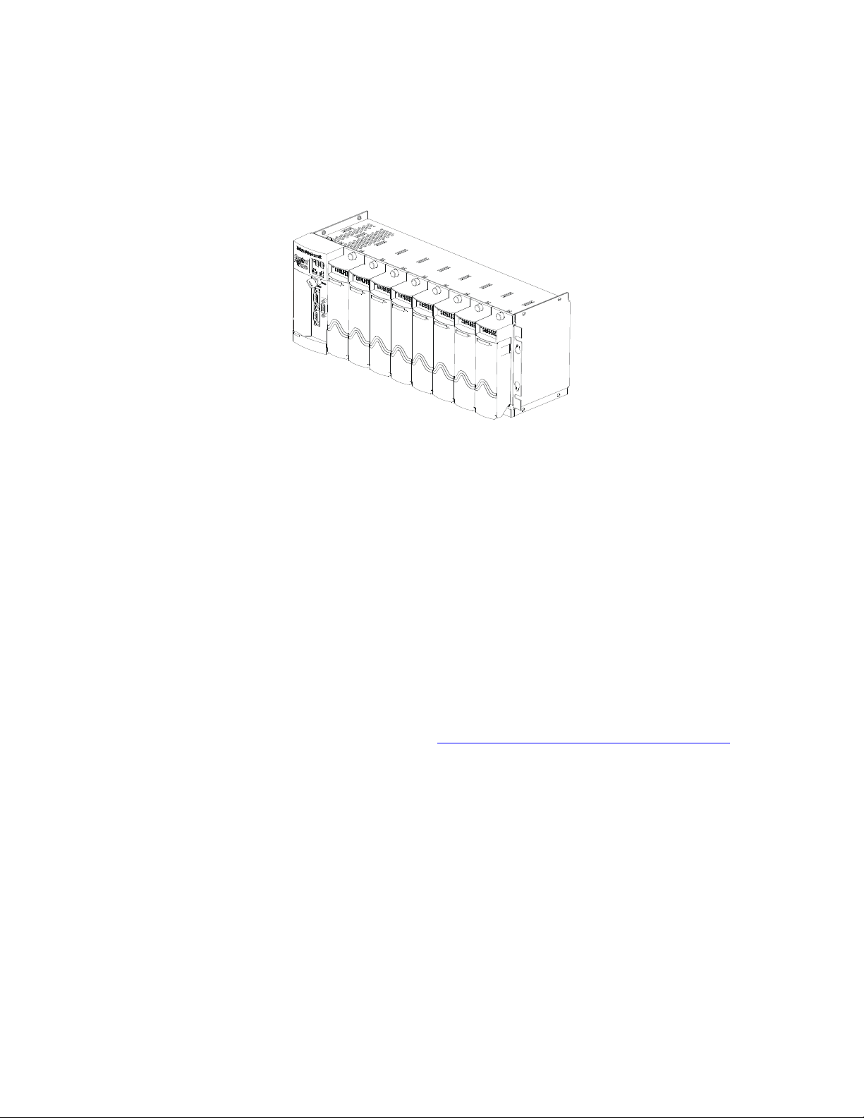
Figure 1-1. ControlWave with 8 I/O Modules
1-2 Introduction Revised Nov-2010
Page 9

1.3 Housings
ControlWave Instruction Manual (CI-ControlWave)
Refer to the following sections in this chapter or to other chapters in this
manual for further information:
Housings (chassis) with backplanes (see Section 1.3 and Chapter 2)
Power Supply/Sequencer module (PSSM) (see Section 1.5 and
Chapter 2)
CPU module (see Section 1.4 and Chapter 2)
One or more I/O modules (see Section 1.6 and Chapter 3)
ControlWave housings are stainless steel designed for panel-mounting
or for some versions, for mounting in a 19-inch equipment rack. They
contain the printed circuit board (PCB) backplane into which you
connect the PSSM, the CPU module, and any I/O modules.
The following housings are available:
6-slot backplane supports one PSSM, one CPU, and up to four I/O
modules.
10-slot housing supports one PSSM, one CPU, and up to eight I/O
modules. The 10-slot housing is suitable for mounting in a 19-inch
equipment rack.
Revised Nov-2010 Introduction 1-3
Page 10
ControlWave Instruction Manual (CI-ControlWave)
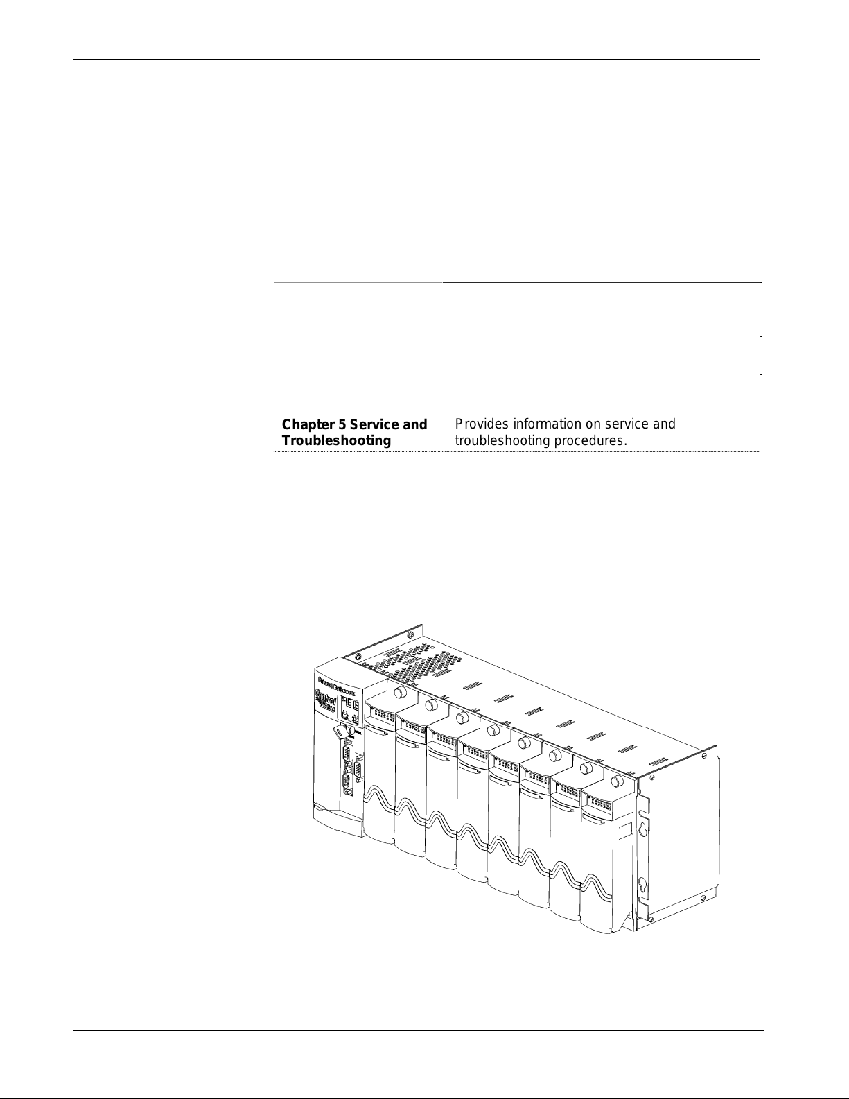
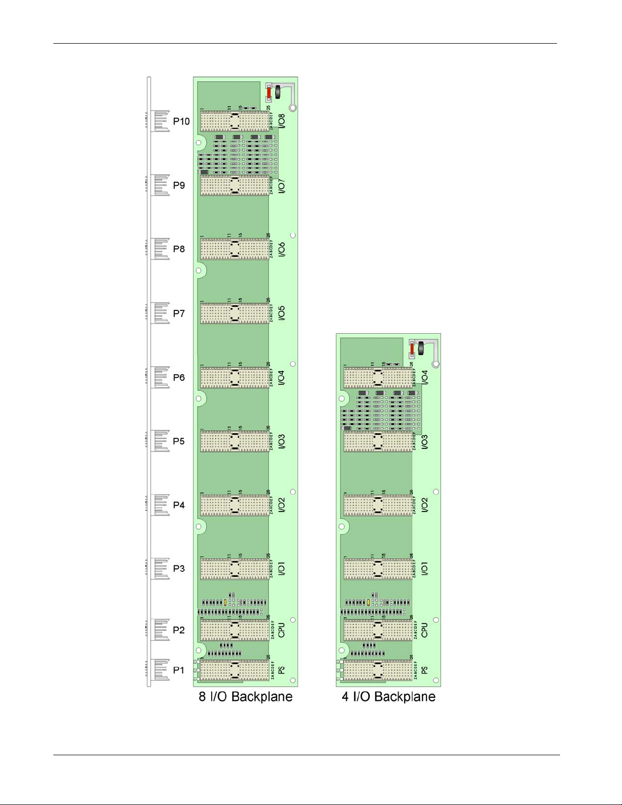
Figure 1-2. ControlWave Housing Options
1-4 Introduction Revised Nov-2010
Page 11

1.4 CPU Module
ControlWave Instruction Manual (CI-ControlWave)
Note: For detailed technical specifications, please see document
CWPAC available on our website
http://www.emersonprocess.com/remote.
The CPU (central processing unit) module houses the multi-layer PCB,
which contains the ControlWave CPU, I/O monitor/control, memory,
and communication functions. It also may include the optional
Secondary Communications Board (SCB).
The CPU module includes:
AMD Elan SC520 microprocessor running at 100 MHz
two RS-232 communication ports
one 10/100baseT Ethernet port
2 MB of battery backed Static RAM (SRAM)
64 MB of Synchronous Dynamic RAM (SDRAM)
512 KB boot/downloader FLASH
32 MB simultaneous read/write FLASH memory
CPU Module
Configurations
Number of
RS-232
Ports
2 0 1 No SCB.
3 1 2 For this port count, 1 RS-232, 1 RS-485,
3 1 1 For this port count, 1 RS-232 and 1 RS-
2 2 1 For this port count, both RS-485 ports
transmit (TX) and receive (RX) LEDs for each communication port
Keyed run/remote/local operation switch
configuration DIP switches (described in Chapter 2)
Port 80 display to show status codes
You can order the CPU module with the optional secondary
communication board (SCB) for additional communication ports. See
CPU Module Configurations.
The CPU module has several basic configurations, all of which have an
on-board backup battery and different combinations of
communications ports.
Table 1-1. CPU Module Configurations
Number of
RS-485
Ports
Number of
Ethernet Ports
Notes
and 1 Ethernet port reside on the SCB.
485 port reside on the SCB.
reside on the SCB.
Revised Nov-2010 Introduction 1-5
Page 12

ControlWave Instruction Manual (CI-ControlWave)
CPU Backup Battery
CPU Memory
The CPU module includes a 3.6V, 950 mA-hr lithium ½ AA battery.
This battery provides backup power for the real-time clock, CMOS
RAM (within the microprocessor) and the system’s Static RAM
(SRAM).
There are several different types of memory used on the CPU module:
Boot/Downloader FLASH
Boot/download code is contained in a single 512 Kbyte FLASH chip.
Boot FLASH also holds the value of soft switches, audit/archive file
configurations, and user account and port information.
FLASH Memory
The CPU module contains 32 MB of FLASH memory. The FLASH
memory holds the system firmware and the boot project. Optionally
FLASH memory also stores the zipped ControlWave project (*.zwt),
user files, and historical data (audit/archive files).The FLASH does not
support hardware write protection.
System Memory (SRAM)
The CPU module has 2 MB of static random access memory (SRAM).
During power loss periods, SRAM enters data retention mode (powered
by the CPU backup battery). Critical system information that must be
retained during power outages or when the system has been disabled for
maintenance is stored here. This includes the last states of all I/O points,
audit/archive historical data (if not stored in FLASH), the values of any
variables marked RETAIN, the values of any variables assigned to the
static memory area, and any pending alarm messages not yet reported.
SDRAM
The CPU module contains 64MB of synchronous dynamic random
access memory (SDRAM). SDRAM holds the running application
(ControlWave project) as well as a copy of system firmware and the
current values of any variables not marked RETAIN or stored in the
static memory area. This allows the system to run faster than it will
from the SRAM memory. SDRAM is not battery-backed.
CMOS RAM
The Elan microprocessor includes 124 bytes of complementary metal
oxide semiconductor (CMOS) RAM to hold various internal
parameters.
1-6 Introduction Revised Nov-2010
Page 13

ControlWave Instruction Manual (CI-ControlWave)
1.5 Power Supply/Sequencer Module (PSSM)
Note: If you need redundant power supply capabilities, you can install
a Redundant Power Supply/Sequencer Module (RPSSM) instead
of the PSSM. For details on the RPSSM, see Appendix P.
The Power Supply/Sequencer module (PSSM) takes power from an
external bulk DC power supply and then provides power through the
ControlWave housing/backplane to all installed modules.
The PSSM operates from +22.2 to +30V (dc) and ships from the factory
with a nominal input supply configuration of 24V.
The PSSM includes:
ON/OFF system power switch
Pluggable terminal block to connect the external power supply
Watchdog output connector to signal a watchdog failure to an
external device
Status LEDs
Chapter 2 includes instructions for installing and configuring the PSSM.
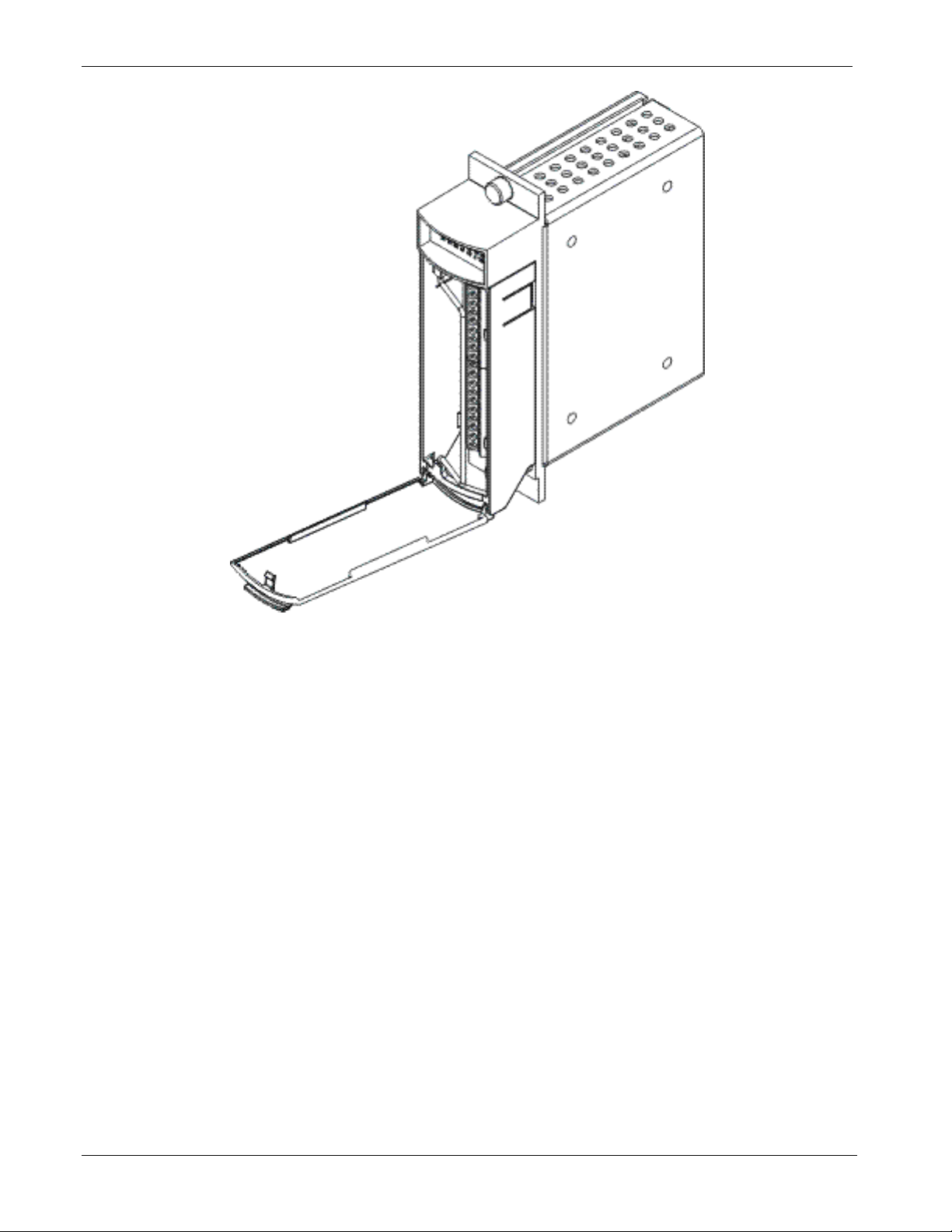
1.6 I/O Modules
The ControlWave supports analog input, analog output, digital input,
digital output, universal digital input, isolated RTD, and isolated low
level analog input modules for either local or remote field device wiring
termination.
Refer to Chapter 3 for information on specific I/O modules. Figure 1-3
shows a typical I/O module housing.
Terminations are pluggable and accept a maximum wire size of #14
AWG. All I/O modules have surge protection that meets either C37.901978 or 472-1978 IEEE specifications.
Each I/O module connects to the backplane using a 110-pin male
connector and to its associated terminal block assembly using a 44 pin
header.
Revised Nov-2010 Introduction 1-7
Page 14
ControlWave Instruction Manual (CI-ControlWave)
1.7 Software Tools
Figure 1-3. I/O Module (with door open)
The ControlWave programming environment consists of a set of
integrated software tools which allow you to create, test, implement,
and download complex control strategies for use with the ControlWave.
Figure 1-4 graphically presents the programming environment.
1-8 Introduction Revised Nov-2010
Page 15
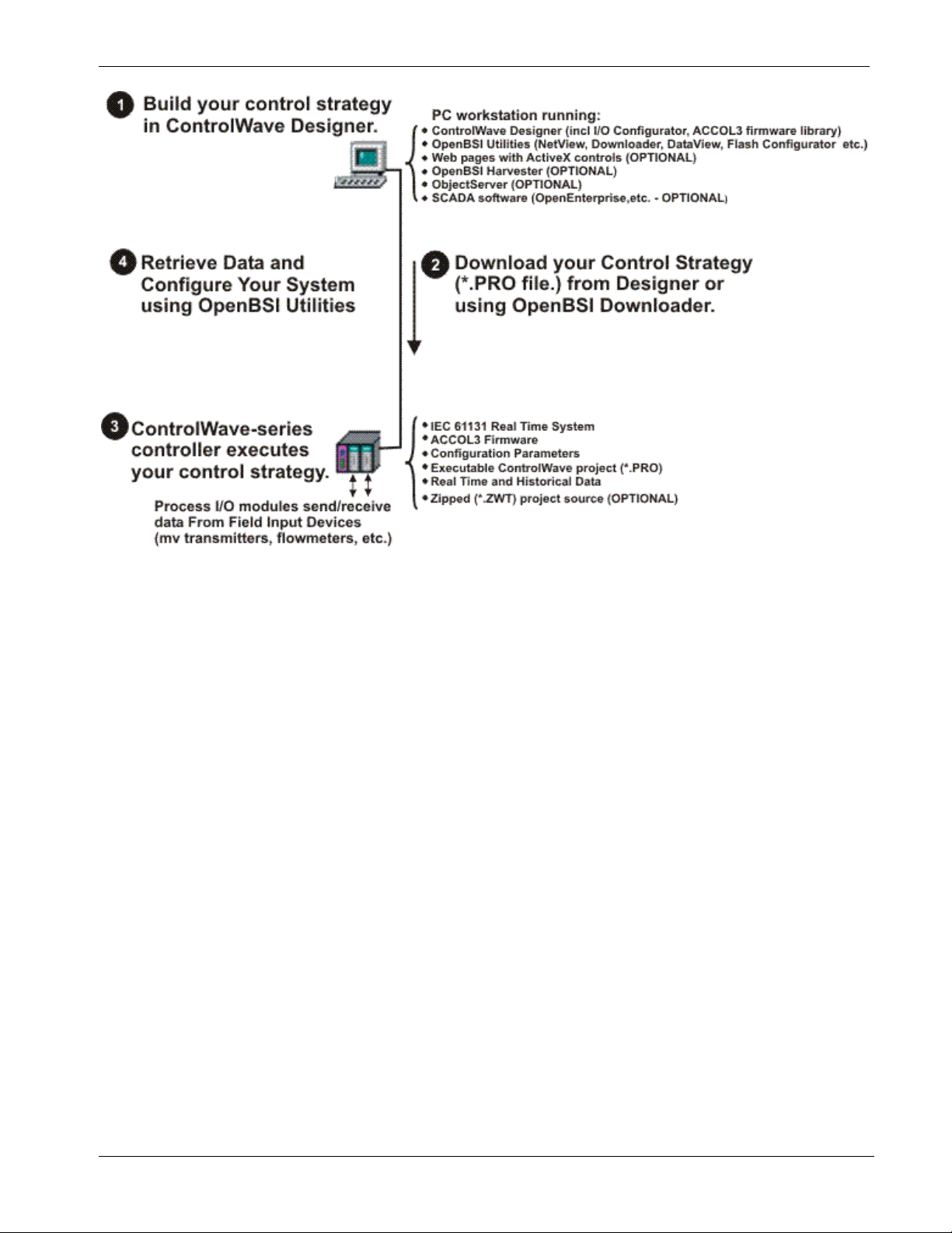
ControlWave Instruction Manual (CI-ControlWave)
Figure 1-4. ControlWave Programming Environment
The tools which make up the programming environment include:
ControlWave Designer is your load-building package. It offers
several different methods for you to create control strategy programs
that run in your ControlWave. You can use pre-made function
blocks, ladder logic, or structured languages. The resulting process
control strategy programs (called projects) are fully compatible
with IEC 61131 standards. For information on ControlWave
Designer, see the Getting Started with ControlWave Designer
manual (document D5085), the ControlWave Quick Setup Guide
(document D5084), and the ControlWave Designer Programmer’s
Handbook (document D5125).
The I/O Configurator, accessible via a menu item in ControlWave
Designer, allows you to define process I/O modules in the
ControlWave and configure the individual mapping of I/O points for
digital and analog inputs and outputs. For information on the I/O
Configurator see
the ControlWave Designer Programmer’s
Handbook (document D5125).
Revised Nov-2010 Introduction 1-9
Page 16

ControlWave Instruction Manual (CI-ControlWave)
The ACCOL3 Firmware Library, available within ControlWave
Designer, includes a series of ControlWave-specific function blocks.
These pre-programmed function blocks let you accomplish various
tasks common to most user applications including alarming,
historical data storage, as well as process control algorithms such as
PID control.
For information on individual function blocks, see the
online help within ControlWave Designer.
OpenBSI Utilities provides a set of programs that allow you to
configure a communication network of ControlWave controllers,
download files to the controllers, and collect data from the network.
OpenBSI also exports data from the network to a SCADA/host
package, such as OpenEnterprise. For information on configuring
OpenBSI communications, see the OpenBSI Utilities Manual
(document D5081).
OpenBSI Harvester is a special add-on package that allows
scheduled data collections from large networks. For information on
the Harvester, see the OpenBSI Harvester Manual (document
D5120).
Communication
Protocols
A series of web page controls are available for retrieval of real-time
data values and communication statistics. These controls utilize
ActiveX technology and are called through a set of fixed web pages,
compatible with Microsoft® Internet Explorer. Alternatively,
developers can place the controls in third-party ActiveX compatible
containers such as Visual BASIC or Microsoft® Excel. For
information on the ActiveX controls, see the Web_BSI Manual
(document D5087).
User-defined web pages - If desired, you can use the ActiveX web
controls in your own user-defined web pages you can store at the PC
to provide a customized human-machine interface (HMI).
Flash Configuration Utility – Parameters such as the BSAP local
address, IP address, etc. are set using the Flash Configuration
Utility, accessible via OpenBSI LocalView, NetView, or TechView.
For information on the Flash Configuration Utility, see Chapter 5 of
the OpenBSI Utilities Manual (document D5081).
In addition to the Bristol Synchronous/Asynchronous Protocol
(BSAP), ControlWave supports communications using:
Internet Protocol (IP) - You can use an Ethernet port or use a serial
port using serial IP using Point-to-Point Protocol (PPP).
Other supported protocols include: Modbus, Allen-Bradley DF1, CIP,
DNP3, and Hex Repeater. See the ControlWave Designer online help
for details and restrictions.
1-10 Introduction Revised Nov-2010
Page 17
Chapter 2 – Installation
This chapter discusses the physical configuration of the ControlWave,
considerations for installation, wiring instructions for the PSSM
module, and instructions for setting switches and jumpers on the CPU
module. For instructions on I/O installation, see Chapter 3.
In This Chapter
2.1 ..........................................................................2-1 Site Considerations
.............................2-2 Class I, Div 2 Installation Considerations
2.1.1
........................................................................2-2 Installation Overview
2.2
.......................................................2-3 Unpacking Components
2.2.1
..........................................2-4 Color Coding of Slot Connectors
2.2.2
..........................................................2-4 Mounting the Housing
2.2.3
........................................................2-6 Grounding the Housing
2.2.4
.....................................2-7 Power Supply/Sequencer Module (PSSM)
2.3
..................................2-9 General Information about the PSSM
2.3.1
.................................................2-9 PSSM Installation Overview
2.3.2
.................................................2-10 General Wiring Guidelines
2.3.3
...................2-10 Wiring a Bulk DC Power Supply to the PSSM
2.3.4
2.3.5
..................................................................................2-18 CPU Module
2.4
.........................2-19 Setting DIP Switches on the CPU Module
2.4.1
................................2-22 Connections to RS-232 Serial Port(s)
2.4.2
2.4.3
........2-29 Connections to Ethernet Port(s) on the CPU Module
2.4.4
............................................................................................2-30 Bezels
2.5
ControlWave Instruction Manual (CI-ControlWave)
Wiring an External Alarm or Annunciator to the Watchdog
Connector and Wiring the Redundancy Control Input
(OPTIONAL)
Connections to RS-485 Serial Port(s) on the Secondary
Communication Board (SCB)
.....................................................................2-15
...........................................2-27
2.1 Site Considerations
When choosing an installation site, check all clearances. Ensure that the
ControlWave is accessible for wiring and service.
To ensure safe use of this product, please review and follow the
Caution
Revised Nov-2010 Installation 2-1
instructions in the following supplemental documentation:
Supplement Guide - ControlWave Site Considerations for
Equipment Installation, Grounding, and Wiring (S1400CW)
ESDS Manual – Care and Handling of PC Boards and ESD
Sensitive Components (S14006)
Page 18
ControlWave Instruction Manual (CI-ControlWave)
Specifications
for Temperature,
Humidity and
Vibration
Caution
2.1.1 Class I, Div 2 Installation Considerations
See document CWPAC available on our website for detailed
technical specifications for temperature, humidity, and vibration for
the ControlWave. This document is available on our website at:
http://www.emersonprocess.com/remote.
Ensure that the ambient temperature and humidity at the installation
site remains within these specifications. Operation beyond the
specified ranges could cause output errors and erratic performance.
Prolonged operation under extreme conditions could also result in
failure of the unit.
Check the mounted enclosure, panel, or equipment rack for
mechanical vibrations. Make sure that the ControlWave is not
exposed to a level of vibration that exceeds that provided in the
technical specifications..
Placement of the ControlWave in Class 1, Division 2 (Group A, B, C, and
D) hazardous locations requires that you select an appropriate
enclosure that meets NEMA Type 3X or 4X specifications.
Underwriters Laboratories (UL) lists the ControlWave as non-incendive
and suitable only for use in Class I, Division 2, Group A, B, C, and D
hazardous locations and non-hazardous locations. Read this chapter and
Appendix A carefully before you install a ControlWave in a hazardous
location.
Perform all power and I/O wiring in accordance with Class I, Division 2
wiring methods as defined in Article 501-4 (b) of the National Electrical
Code, NFPA 70 (for installations within the United States) or as
specified in Section 18-152 of the Canadian Electrical Code (for
installation in Canada).
WARNING
EXPLOSION HAZARD
Substitution of components may impair suitability for use in Class I,
Division 2 environments.
When the ControlWave is situated in a hazardous location, turn off
power before servicing or replacing the unit and before installing or
removing I/O wiring.
Do not connect or disconnect equipment unless the power is switched
off or the area is known to be non-hazardous.
2.2 Installation Overview
Installing a ControlWave involves several general steps:
1. Unpacking, assembling, and configuring the hardware
2. Installing PC-based software (ControlWave Designer)
2-2 Installation Revised Nov-2010
Page 19
ControlWave Instruction Manual (CI-ControlWave)
3. Establishing communications
4. Creating an application-specific control strategy (ControlWave
project).
5. Creating application-specific web pages (optional)
6. Adding the ControlWave to an OpenBSI network
7. Downloading the application-specific ControlWave project into the
ControlWave
Note: Steps 2 through 7 require that you install and use ControlWave
Designer software on your PC. This manual focuses on hardware
installation and preparation. Software installation and
configuration is beyond the scope of this manual. Refer to the
ControlWave Quick Setup Guide (D5084) for material related to
software installation and use.
2.2.1 Unpacking Components
Packaging
Depending upon how you order it, the ControlWave Micro may arrive
pre-assembled, with all modules installed in the housing, or as
individual components in a number of separate boxes. In the latter case,
you must identify, unpack, and assemble the components. Unless
otherwise noted, you can place modules in any slot in a base or
expansion housing.
Note: Do not install modules in the housing until you have mounted
and grounded the housing at the designated installation site.
Delivered boxes may include:
Housing assemblies
Power Supply/Sequencer module (PSSM)
Note: The PSSM must reside in slot #1 in the base housing.
CPU module
Note: The CPU module must reside in slot #2 in the base housing.
I/O Modules
Notes:
There are many different types of I/O modules available. Chapter
3 contains detailed instructions on each I/O module.
Universal Digital Input (UDI) modules can only reside in the first
four I/O slots.
One or more bezel assemblies; each bezel covers two I/O
modules.
Revised Nov-2010 Installation 2-3
Page 20

ControlWave Instruction Manual (CI-ControlWave)
2.2.2 Color Coding of Slot Connectors
A color tab on each backplane connector matches the color on the
module which you can place in that slot.
PSSM goes in the first slot (Yellow tab)
CPU goes in the second slot (Blue tab)
I/O modules go in any other slot (Green tab)
2.2.3 Mounting the Housing
You can install a ControlWave equipped with a 4-I/O module housing
on a wall or panel. See Figure 2-2 for mounting hole patterns for a 4-
I/O unit.
You can install a ControlW
ave equipped with an 8-I/O module housing
in a 19-inch equipment rack, a panel or a wall. These units ship from the
factory with the end plates configured for 19-inch rack mounting.
Remove the end plates, rotate them 180° and then reinstall them to
accommodate panel or wall mounting. See Figure 2-1 for hole patterns
and dimensions.
When you install any of these units on a panel or wall, position it
according to the following restrictions:
Position the unit so that you can see the front of the assembly and so
it is accessible for service such as installing a module or replacing a
battery.
Do not install ControlWave modules until you mount the housing
and ground it properly.
2-4 Installation Revised Nov-2010
Page 21
ControlWave Instruction Manual (CI-ControlWave)
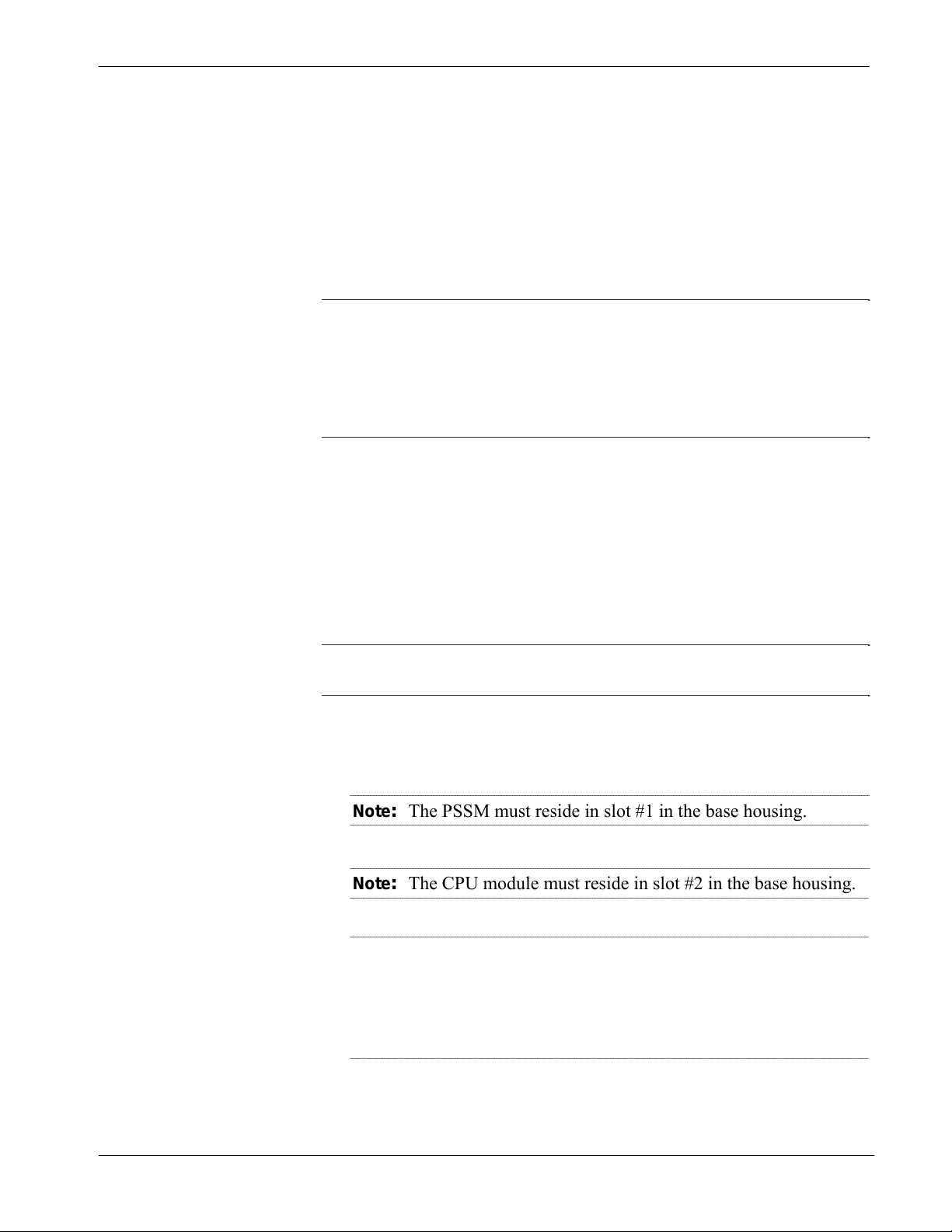
Figure 2-1. 8-I/O Module ControlWave - Mounting Diagram
Revised Nov-2010 Installation 2-5
Page 22
ControlWave Instruction Manual (CI-ControlWave)
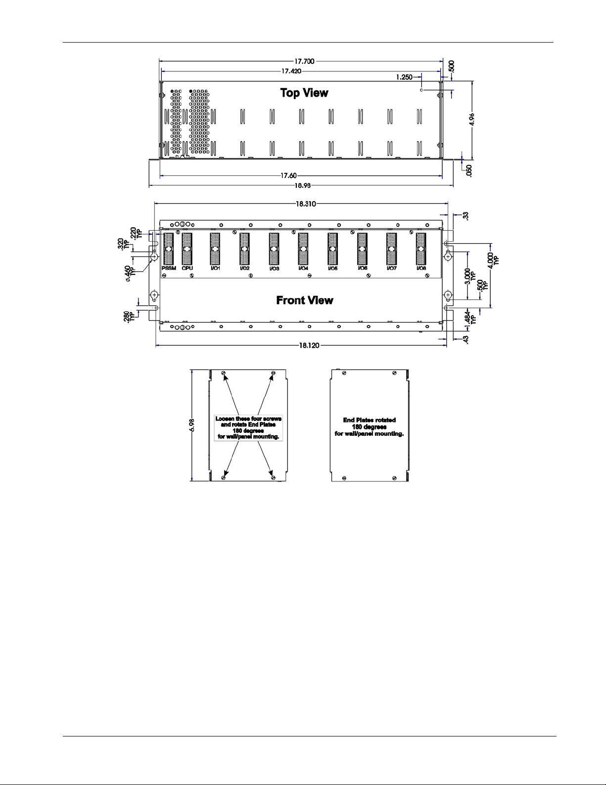
Figure 2-2. 4-I/O Module ControlWave - Mounting Diagram
2.2.4 Grounding the Housing
Caution
2-6 Installation Revised Nov-2010
Do not install any modules in the housing until you mount and ground
the housing at the designated installation site.
Housings have a ground lug that accommodates up to a #4 AWG wire
Once you install the housing, you must run a ground wire between
size.
the housing ground lug and a known good earth ground.
When you install the various ControlWave modules into the housing
and secure them using the captured panel fasteners, this automatically
connects them to chassis ground.
Page 23

ControlWave Instruction Manual (CI-ControlWave)
Note: After you install the PSSM in the housing, as an added
precaution we recommend that you run a #14 AWG wire from
the TB2-5 power connection (chassis ground) to the same known
good earth ground.
Additional grounding guidelines include:
Use stranded copper wire (#4 AWG) for the housing to earth
ground, and keep the length as short as possible.
Clamp or braze the ground wire to the ground bed conductor
(typically a stranded copper AWG 0000 cable installed vertically or
horizontally).
Tin the wire ends with solder (using a high-wattage soldering iron)
prior to inserting the wire into the housing ground lug.
Run the ground wire so that any routing bend in the cable has a
minimum radius of 12-inches below ground and 8-inches above
ground.
2.3 Power Supply/Sequencer Module (PSSM)
Before we actually install the PSSM it in the housing, we’re going to
discuss some general information about how it works.
Revised Nov-2010 Installation 2-7
Page 24
ControlWave Instruction Manual (CI-ControlWave)
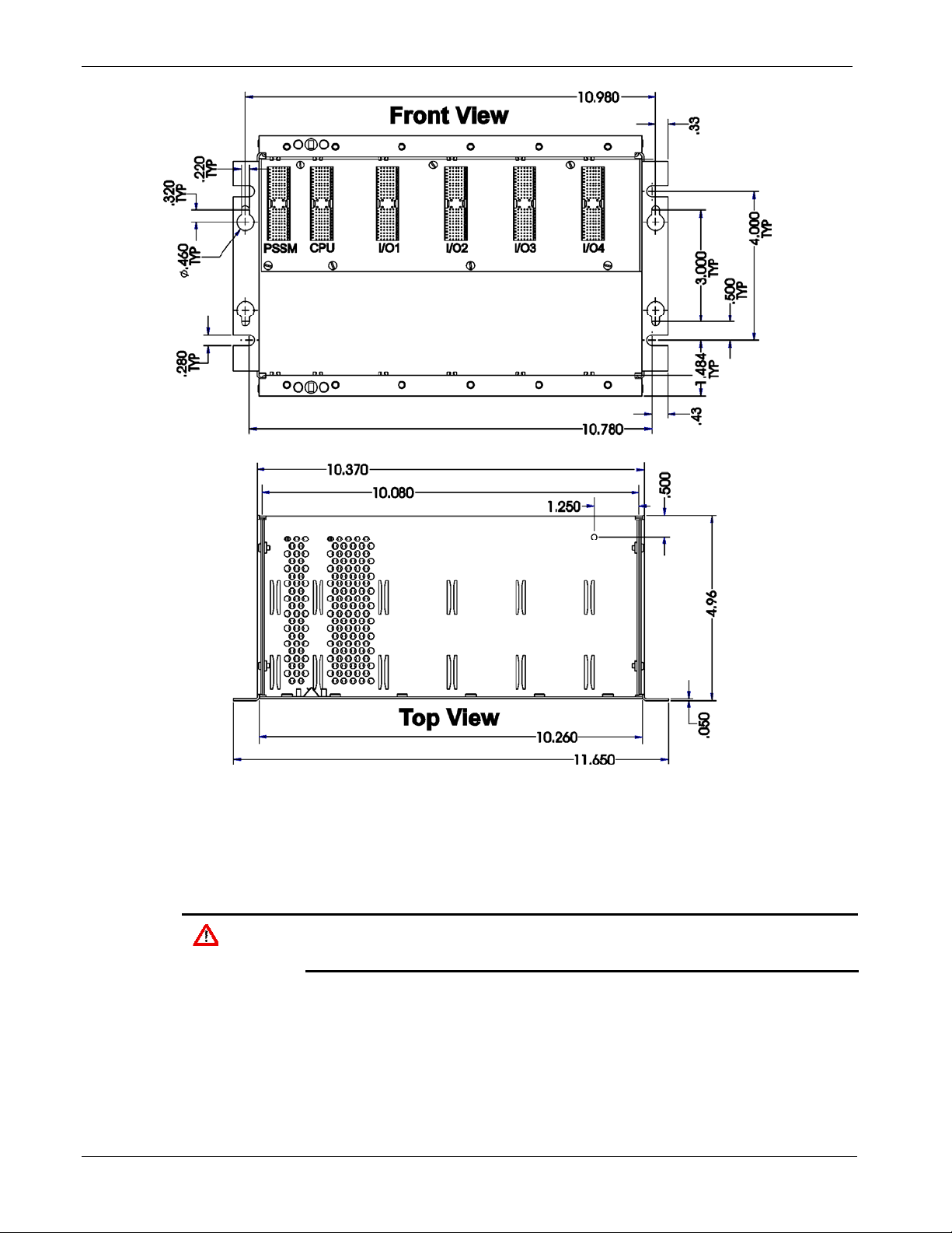
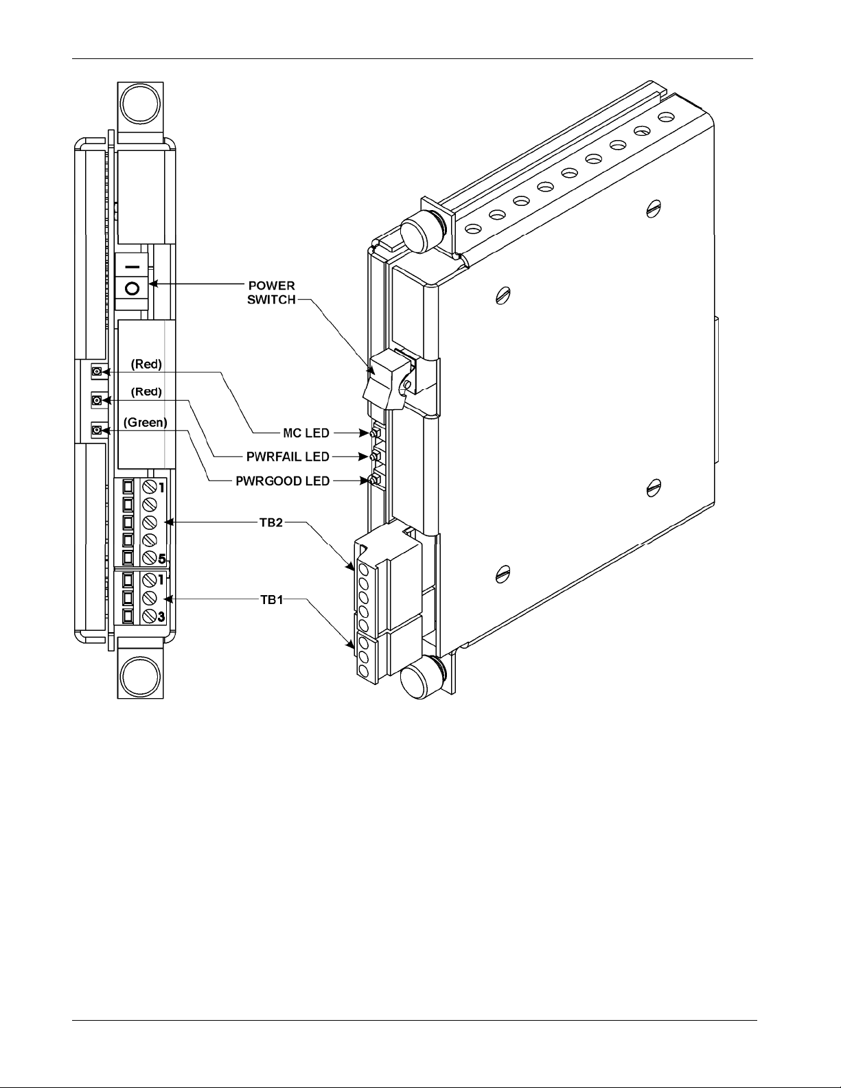
Figure 2-3. Power Supply/Sequencer Module (PSSM)
2-8 Installation Revised Nov-2010
Page 25
ControlWave Instruction Manual (CI-ControlWave)
2.3.1 General Information about the PSSM
The Power Supply/Sequencer module (PSSM) takes power from an
external bulk DC power supply and then provides power through the
ControlWave housing/backplane to all installed modules.
The Power Supply/Sequencer module (PSSM) plugs into slot #1 (first
slot from the left) on the ControlWave’s backplane using connector J1.
Power
Supply
Hot Swap of I/O
Modules
WARNING
Watchdog
Switch
Redundancy
Control Input
The PSSM ships from the factory configured for a nominal input supply
of 24Vdc.
The PSSM supports “hot swapping” of I/O modules. This means you
can insert or remove an I/O module from the chassis while power is
live. There is no support for “hot swapping” of the PSSM itself, or the
CPU module.
Do not perform “hot swapping” in a Class I, Division 2 hazardous
location.
PSSMs include a watchdog metal oxide semiconductor field-effect
transistor (MOSFET) switch connector. The purpose of the watchdog
connector is to trigger an external alarm or annunciator if the
ControlWave enters a “watchdog” condition in which the CPU cannot
control your process. This occurs on power-up before the ControlWave
project starts, if the unit is reset, if the ControlWave project “crashes”
or if the system loses power. See Section 2.3.5.
The same terminal block (TB1) used for watchdog control also handles
a redundancy control line to a ControlWave Redundant I/O Switcher.
See Section 2.3.5.
2.3.2 PSSM Installation Overview
There are several steps you need to follow when you install the PSSM.
1. Identify the carton holding the PSSM and remove it from that carton.
See Section 2.2.1.
2. Slide the PSSM into slot #1 of the housing.
3. Tighten the captured panel fasteners to secure the PSSM in place.
4. Unplug terminal block connector TB2 from the PSSM and wire it to
an external bulk DC power supply. See Section 2.3.4.
5. If you want to use the watchdog connector TB1, or use this
ControlWave in a redundant system, unplug TB1 from the PSSM and
wire it to an external annunciator or similar device according to
instructions in Section 2.3.5 .
6. After you configure and install the CPU module in slot #2 re-connect
Revised Nov-2010 Installation 2-9
Page 26

ControlWave Instruction Manual (CI-ControlWave)
terminal blocks to their connectors to apply power to the unit.
2.3.3 General Wiring Guidelines
ControlWave PSSMs use compression-type terminals that
accommodate up to #14 AWG wire.
When making a connection, insert the bare end of the wire (approx
¼” max) into the clamp adjacent to the screw and secure the wire.
To prevent shorts, ensure that no bare wire is exposed. If using
standard wire, tin the bare end with solder to prevent flattening and
improve conductivity.
Allow some slack in the wire while making terminal connections.
Slack makes the wires more manageable and helps minimize
mechanical strain on the terminal blocks.
2.3.4 Wiring a Bulk DC Power Supply to the PSSM
Caution
Operating
Range
One or Two
Power
Supplies
At this time you can also connect power and watchdog wiring.
However; for safety reasons and to prevent accidental damage to the
your bulk DC power supply, do not connect the pluggable terminal
block connectors TB1 and TB2 to the PSSM until after you install, wire,
and configure the CPU module.
Follow the instructions in Section 2.3.3 General Wiring Guidelines wh
wiring connections.
en
The ControlWave operates from +22.2 Vdc to +30.0 Vdc (with a
nominal +24Vdc input source).
You can connect one or two bulk DC power supplies (nominally +24
Vdc) to the PSSM.
The bulk DC supply you connect to terminal TB2-1 (+VIN) powers the
CPU, communications, and I/O logic circuits. The PSSM converts,
regulates, and filters the power to +5Vdc, +3.3Vdc, +12Vdc (optional)
and -12Vdc (optional).
+3.3 Vdc. For safety, this circuit has a 3A fuse.
The bulk DC supply (+20.0 to +30Vdc) you connect to terminal TB2-2
(+VINF) powers the I/O field devices connected to the I/O modules. For
safety, this circuit has a 10A fuse.
Notes:
When you require two bulk power supplies, the first supply (VIN)
must be rated to handle 2 amps.
The fuses for the PSSM cannot be replaced in the field.
2-10 Installation Revised Nov-2010
Page 27

ControlWave Instruction Manual (CI-ControlWave)
Calculating the
Maximum Current
Required
Max Bulk +24 Vdc Supply Current = CPU
where
CPU
Σ I/O Module
Use the following formula to determine the maximum current required
for the +24 Vdc bulk power used with a particular ControlWave:
max_current
+ Σ I/O Module
max_current
:
max_current
max_current
refers to the maximum current required by the CPU (with or
without an SCB), backplane and the PSSM. This is 1A.
refers to the sum of the maximum current required by each
and every I/O module installed in the unit. The amount per
I/O module varies as follows:
16 AI Module 2A per module
8 AI Module 1A per module
8 AO Module 1A per module
16 DI Module 1A per module
32 DI Module 1A per module
16 DO Module See table (no surge current)
32 DO Module See table (no surge current)
6 UDI Module See table (no surge current)
4 RTD Module See table (no surge current)
6 LLAI Module See table (no surge current)
So, for example, if you have a ControlWave with a 16AI module, an
8AO module, and a 32DI module, the maximum current draw is 1A for
the CPU plus 2A for the 16AI module plus 1A for the 8AO module and
1A for the 32DI module, for a total of 5A.
Note: This calculation covers current draw during normal operation
(steady state) as well as the current draw during power-up inrush when the unit is first powered on. Power up in-rush current
can last up to 100 milliseconds and is higher than the current
draw required during normal operation.
Refer to Table 2-1 for ControlWave steady state and loop current
requirements for bulk power supplies.
Revised Nov-2010 Installation 2-11
Page 28

ControlWave Instruction Manual (CI-ControlWave)
Table 2-1. Steady State Current Draw for Bulk Power Supplies
Component(s) System Current
draw for 24Vdc
Power Supply
CPU (with Ethernet),
PSSM and backplane
CPU (with Ethernet), SCB
(with Ethernet), PSSM and
backplane
CPU (with Ethernet), SCB
(with 2 RS-232), PSSM
and backplane
Analog Input Module 16
points (4-20 mA)
Analog Input Module 8
points (4-20 mA)
Analog Output Module 8
points (4-20 mA)
Analog Output Module 8
points (1-5V)
Digital Input Module 32
points
Digital Input Module 16
points
Digital Output Module 32
points
Digital Output Module 16
points
Universal Digital Input
(UDI) – 6 points
Isolated RTD 4 point 26.0 mA 0 mA
Isolated Low Level Analog
Input 6 points
290 mA Not applicable
400 mA Not applicable
310 mA Not applicable
40.5 mA 52.2 mA For 24Vdc supply add 25 mA per
36.1 mA 29.7 mA For 24Vdc supply add 25 mA per
20.0 mA 26.9 mA For 24Vdc supply add 23.6 mA
20.0 mA 56.8 mA For 24Vdc supply add 26.1 mA
29.2 mA 29.7 mA For 24Vdc supply add 4.74 mA
15.8 mA 29.7 mA For 24Vdc supply add 4.74 mA
42.6 mA 0 mA
22.6 mA 0 mA
16.7 mA 0 mA
40.0 mA 0 mA
Field Current draw for
24Vdc Power Supply
Notes
loop
loop
per loop
per loop. Output at 5 mA
per loop – dry contact
per loop – dry contact
Terminal Block
Connector TB2
Unplug removable connector TB2 from the PSSM and wire DC power
to the connector. We recommend you do not plug the connector back
into the PSSM until the CPU module is already installed in the housing.
TB2 provides five input connections for bulk power:
TB2-1: = (+VIN) (+22.2V to +30V dc for +24V supply)
TB2-2 = (+VINF) Connected to TB2-1 or +20Vdc to +30Vdc
supply
TB2-3 = (-VIN) 1
TB2-4 = (-VIN) 2
TB2-5 = Chassis Ground - CHASSIS ( )
2-12 Installation Revised Nov-2010
st
supply ground
nd
supply ground internally connected to TB2-3
Page 29
ControlWave Instruction Manual (CI-ControlWave)
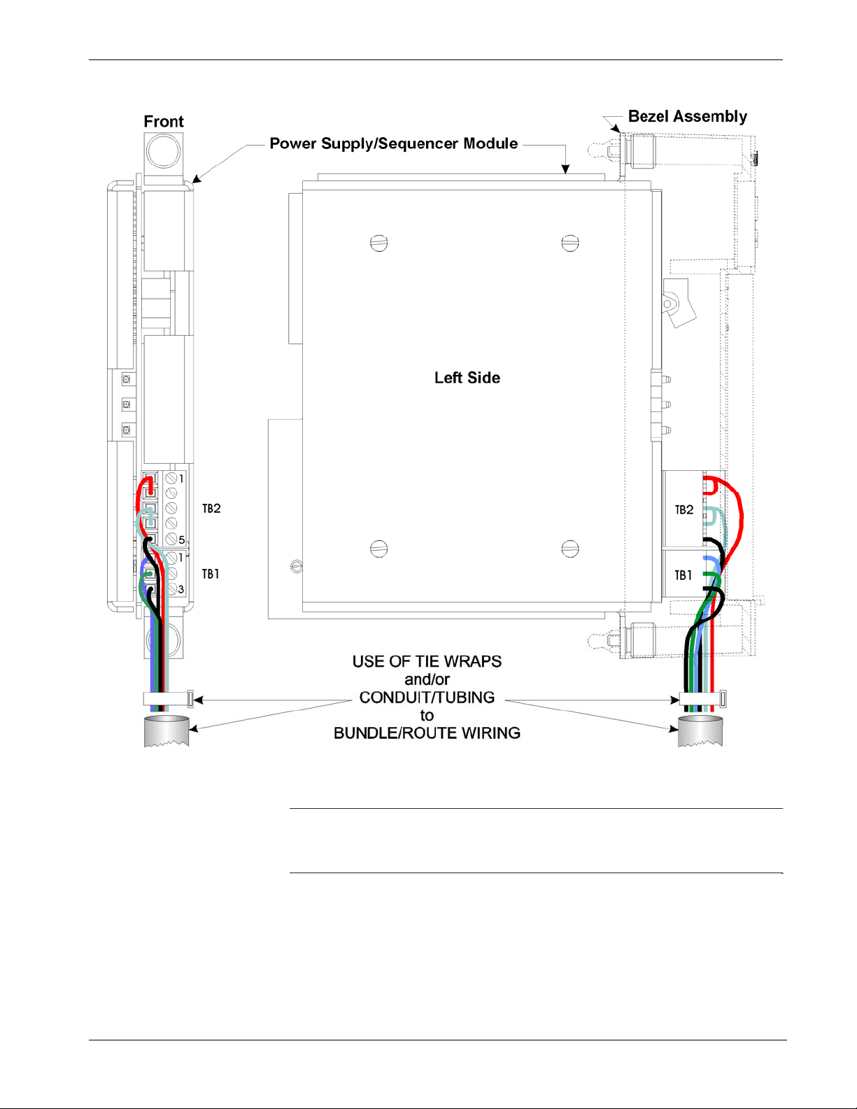
Figure 2-4 shows the typical wiring at the PSSM’s TB1 block.
Figure 2-4. PSSM Wire Routing Diagram
Note
: As an added precaution, we recommend that you run a #14
AWG wire from the TB2-5 power connection (chassis ground)
to the same known good earth ground used for the housing.
Revised Nov-2010 Installation 2-13
Page 30
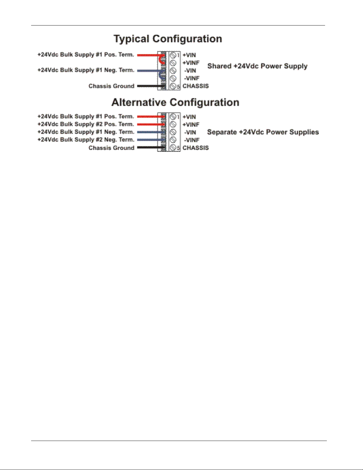
ControlWave Instruction Manual (CI-ControlWave)
Figure 2-5. PSSM TB2 – Typical Wiring Schemes
2-14 Installation Revised Nov-2010
Page 31

ControlWave Instruction Manual (CI-ControlWave)
2.3.5 Wiring an External Alarm or Annunciator to the Watchdog Connector and Wiring the Redundancy Control Input (OPTIONAL)
Caution
Watchdog
Condition
At this time you can also connect power and watchdog wiring.
However; for safety reasons and to prevent accidental damage to the
your bulk DC power supply, do not connect the pluggable terminal
block connectors TB1 and TB2 to the PSSM until after you install, wire,
and configure the CPU module.
Follow the instructions in Section 2.3.3 General Wiring Guidelines wh
wiring connections.
en
The PSSM includes an optional watchdog connector TB1. The purpose
of the watchdog connector is to trigger an external alarm or annunciator
if the ControlWave enters a “watchdog” condition in which the CPU
cannot control your process.
A watchdog condition occurs when:
A watchdog timer expires. This happens if the ControlWave project
execution halts unexpectedly – “program crash.”
The controller powers up but is not yet running the ControlWave
project.
The CPU module detects that the regulated supplies are out of
specification.
Redundancy
Control Input
A MOSFET switch activates the watchdog connector whenever a
watchdog condition occurs. If your ControlWave is part of a redundant
pair, the ControlWave Redundancy Switcher monitors the watchdog
switch to detect a failure of the ControlWave.
The same TB1 connector includes an input from the ControlWave
Redundancy Switcher. If this ControlWave is part of a redundant pair,
and the ControlWave Redundancy Switcher detects a watchdog failure
in the other ControlWave, the redundancy control input sends signals to
this ControlWave that it must take control. For more information on
how this works, see the ControlWave Redundancy Setup Guide (D5123)
and the ControlWave Redundant I/O and Control Switch Unit Manual
(CI-ControlWave REDI/O).
Revised Nov-2010 Installation 2-15
Page 32

ControlWave Instruction Manual (CI-ControlWave)
Terminal Block
Connector TB1
You must power the watchdog connector (TB1) from an external power
supply. Unplug removable connector TB1 from the PSSM and wire
power to the connector. We recommend you do not plug the connector
back into the PSSM until the CPU module is already installed in the
housing.
TB1 provides the following connections:
TB1-1 = VO - Watchdog MOSFET Switch Output
TB1-2 = VI - Watchdog MOSFET Switch Input
TB1-3 = VR = Redundant Unit Control Input
The VI input on TB2 (TB1-2) powers the watchdog switch; its switched
output connects to the VO output on the same terminal block (TB1-1).
You must reference the external power source connected to the VI
terminal to the return point of the input source powering the PSSM
[which is either –VIN or PSGND (TB2-3)]. See Figure 2-6.
TB1-1
TB1-2
TB2-1
TB2-3
TB2-5
Figure 2-6. Watchdog MOSFET Switch Wiring
2-16 Installation Revised Nov-2010
Page 33

ControlWave Instruction Manual (CI-ControlWave)
Figure 2-7. ControlWave to ControlWave RED I/O Redundancy Field Wiring
Revised Nov-2010 Installation 2-17
Page 34

ControlWave Instruction Manual (CI-ControlWave)
2.4 CPU Module
The CPU module, which controls the ControlWave and handles memory
and communication functions, can only be installed in Slot #2 of the
ControlWave backplane.
Identify the carton holding the CPU module and remove it from that
carton. The CPU module has several different configurations, depending
upon whether or not you ordered the CPU with a secondary
communications board (SCB), and if you did order an SCB, which type:
CPU with two RS-232 serial ports, and one Ethernet port. No SCB.
CPU with two RS-232 serial ports, and one Ethernet port. SCB with
one additional RS-232 port, one RS-485 port, and two additional
Ethernet ports.
CPU with two RS-232 serial ports, and one Ethernet port. SCB with
one additional RS-232 and an RS-485 port.
CPU with two RS-232 serial ports, and one Ethernet port. SCB with
two RS-485 ports.
Set DIP switches on the CPU module according to the tables on the next
few pages. After you configure the DIP switches, slide the CPU module
into slot #2 (the second slot from the left) of the housing.
Figure 2-8. ControlWave CPU Module (without SCB)
2-18 Installation Revised Nov-2010
Page 35

ControlWave Instruction Manual (CI-ControlWave)
Figure 2-9. ControlWave CPU Module (with SCB)
2.4.1 Setting DIP Switches on the CPU Module
Before you install the CPU module, you must determine the settings for
its DIP switches. Refer to Figure 2-8 for the location of the DIP switch
banks on the CPU board itself. If you have a secondary
communications board (SCB) you must also refer to Figure 2-9 for the
location of the DIP switch banks on the SCB. Refer to Tables 2-2
through 2-4 for DIP switch setting values.
Note: Examine each bank of DIP switches carefully to note the switch
direction for ON or OFF.
Table 2-2. CPU Module Switch SW1
SW1 Setting Function Mode
1
2
Watchdog
Enable
Lock/Unlock
Soft Switches
Controls whether the system enters a watchdog state
when a crash or system hangup occurs and automatically
restarts. Values are:
ON (Enables watchdog circuit; factory default)
OFF (Disables watchdog circuit and prevents automatic
restart)
Controls the ability to modify soft switches, other
configurations, and flash files. Values are:
ON (Unlocks soft switches and flash files; factory
default).
OFF (Locks soft switches, configurations, and flash files)
Revised Nov-2010 Installation 2-19
Page 36

ControlWave Instruction Manual (CI-ControlWave)
SW1 Setting Function Mode
3
4
5
6
7
8
Use/Ignore
Soft Switches
Core Updump
(see Section
3.6)
SRAM Control Manages SRAM contents following a low power situation
Redundancy
Enable /
Disable
Unit A / Unit B Specifies whether this ControlWave is the “A” or “B” unit in
Enable
WINDIAG
Controls the use of soft switches. Values are:
ON (Enable user-defined soft switches configured in flash
memory; factory default)
OFF (Disable soft switch configuration and use factory
defaults)
Note: Setting both switch 3 and switch 8 to OFF (closed)
Causes the ControlWave to perform a core updump,
provided you have set the mode switch (SW3-3) to
Recovery mode or properly sequenced the Run / Remote /
Local switch on the PSSM. Values are:
ON (Disables core updump; factory default)
OFF (Core updump via PSSM Run/Remote/Local switch
or mode switch SW3-3)
or a power outage. Values are:
ON (Retain values in SRAM during restarts; factory
default)
OFF (Reinitialize SRAM) – Data in SRAM lost during
power outage or re-start.
Specifies whether this ControlWave is part of a redundant
pair. Values are:
ON (Redundancy Disabled. Not part of redundant pair;
factory default)
OFF (Redundancy Enabled. This ControlWave is one of
two in a redundant pair)
a redundant pair. Values are:
ON (“A” unit in the redundant pair; factory default)
OFF (“B” unit in the redundant pair)
Note: If SW1-6 is ON, the system ignores SW1-7.
Suspends normal operation and allows diagnostic
routines. Values are:
ON (Permits normal system operation, including the boot
project, and disables the WINDIAG diagnostics from
running; factory default)
OFF (Allow WINDIAG to run test; disable boot project.)
Note: Setting both switch 8 and switch 3 to OFF (closed)
sets all serial communication ports to 9600 bps
operation. All serial communication ports must be
set at 9600 bps before WINDIAG can perform
communication tests.
sets all serial communication ports to 9600 bps
operation. All serial communication ports must be
set at 9600 bps before WINDIAG can perform
communication tests.
2-20 Installation Revised Nov-2010
Page 37

ControlWave Instruction Manual (CI-ControlWave)
Table 2-3. CPU Module Switch SW3
SW3 Setting Function Mode
1
2
3
4
N/A Not currently used.
System
Firmware load
control
Force
Recovery
Mode
Backup Battery
Enable/Disable
Enables / disables remote system firmware upgrade via
System Firmware Downloader:
ON (disables remote system firmware upgrade)
OFF (enables remote system firmware upgrade; factory
default)
Note: Remote system firmware upgrade using System
Firmware Downloader requires boot PROM version 06
(or newer) and system PROM version 4.7 (or newer).
Enables recovery mode. This allows for system firmware
upgrades. Values are:
ON (enables recovery mode)
OFF (disables recovery mode). – This is the factory
default.
Enables/disables the backup battery for SRAM and the
real-time clock. Values are:
ON (enables backup battery)
OFF (disables backup battery). – This is the factory
default.
Note: The unit ships from the factory with the backup
battery disabled to conserve battery power. Set this to
ON when you install the CPU.
Notes:
Table 2-4 describes switch settings for ports on the SCB board. You
may want to review Section 2.4.3 before you set these switches.
Table 2-4 applies to the following switches:
o SW1 on the SCB board – controls COM3
o SW2 on the SCB board – controls COM4
COM4 is always an RS-485 port.
Table 2-4. SCB Port Configuration Switches (For COM3 use SW1, for COM4 use SW2)
SCB
SW1 or SW2
Switch
Number
1 ON DTR to DSR Loopback (Use
2 ON TXD to RXD Loopback (Use
Function if this is an RS-232
Port
for Diagnostics only)
OFF No loopback (factory
default)
for Diagnostics only)
Function if this is an RS-485 Port
ON TX+ to RX+ Loopback (Use for
Diagnostics or 2-wire only)
OFF No loopback (factory default)
ON TX- to RX- Loopback (Use for
Diagnostics or 2-wire only)
Revised Nov-2010 Installation 2-21
Page 38

ControlWave Instruction Manual (CI-ControlWave)
SCB
SW1 or SW2
Switch
Number
3
4
5 ON RTS to CTS Loopback (Use
6
Function if this is an RS-232
Port
OFF No loopback (factory
default)
Not currently used
Not currently used
for Diagnostics only)
OFF No loopback (factory
default)
Not currently used
Function if this is an RS-485 Port
OFF No loopback (factory default)
ON 100 Ohm RX+ termination (end
node)
OFF Not an end node (factory
default)
ON 100 Ohm RX- termination (end
node)
OFF Not an end node (factory
default)
Not currently used
ON (Fast slew rate enabled)
OFF (Slow slew rate enabled) (factory
default)
7
8
Not currently used
Not currently used
After you set the DIP switches and insert the CPU module in slot #2 of
the housing, you can connect communication ports.
2.4.2 Connections to RS-232 Serial Port(s)
An RS-232 port provides point-to-point, half-duplex and full-duplex
communications (for a maximum of 20 feet using data quality cable).
The standard CPU module includes two RS-232 ports. If you purchased
your CPU module with a secondary communication board (SCB) you
may have one additional RS-232 port, depending upon the type of SCB.
RS-232 COM
Port Names and
Connectors
RS-232 COM ports are assigned names based on their location in the
ControlWave. The CPU board has two RS-232 ports (COM1 and
COM2). See Table 2-5.
ON RX+ bias (end node)
OFF Not an end node (factory
default)
ON RX- bias (end node)
OFF Not an end node (factory
default)
2-22 Installation Revised Nov-2010
Page 39

ControlWave Instruction Manual (CI-ControlWave)
Table 2-5. RS-232 Connectors on CPU Board
Connector Name Function Notes
J2 COM1 9-pin male D-sub (RS-232) See Figure 2-10 & Table 2-7
J3 COM2 9-pin male D-sub (RS-232) See Figure 2-10 & Table 2-7
If you purchased an SCB board, it may include an RS-232 port. If
present, the RS-232 port on the SCB is COM3 and it has a different type
of connector than that used for COM1 or COM2.
Note: COM3 on the secondary communication board (SCB) can be
ordered as an RS-485 port, in which case it will not function as
an RS-232 port.
Table 2-6. RS-232 Connectors on Secondary Communications Board (SCB)
Connector Name Function Notes
J2 COM3 8-pin RJ-45 (RS-232) See Figure 2-11 & Table 2-8
RS-232 COM
Port Cables
For the ControlWave, half-duplex communications use BSAP protocol
or another protocol such as Modbus, while full-duplex communications
use point-to-point protocol (PPP). RS-232 ports use a “null modem”
cable (see Figure 2-12) to connect with other devices (such as a PC, a
printer, another ControlWave [except the CW_10/30/35]) when the
ControlWave uses the full-duplex PPP protocol.
If you don’t want to make your own cables, as described in this section,
you can purchase cables.
You can purchase a null modem cable using part number 392843-
01-3.
For RJ-45 connectors (for example COM3 on the SCB) you can
purchase RJ45 to DB9 Adapter cable(s) using part number 39284401-0 to use with the null modem cable.
Note: You can configure the ControlWave as either a master or slave
node on a BSAP network.
Figure 2-10 illustrates the CPU module’s male 9-pin D-type connector.
Use the content provided in Table 2-7 to determine pin assignments for
the COM1 and COM2 ports.
Revised Nov-2010 Installation 2-23
Page 40

ControlWave Instruction Manual (CI-ControlWave)
Figure 2-10. Male DB9 9-Pin Connector
Table 2-7. COM1 & COM2 RS-232 Port Connector Pin Assignment
Pin
1 DCD Data Carrier Detect Input
2 RXD Receive Data Input
3 TXD Transmit Data Output
4 DTR Data Terminal Ready Output
5 GND Signal/Power Ground
6 DSR Data Set Ready Input
7 RTS Request to Send Output
8 CTS Clear to Send Input
9 RI Ring Indicator
RS-232
Signal
RS-232 Description
Figure 2-11 shows the RJ-45 connector used for COM3 on the SCB. If
you ordered COM3 as an RS-232 port, see Table 2-8 for pin
assignments.
Figure 2-11. RJ-45 Connector Associated with COM3 (SCB)
2-24 Installation Revised Nov-2010
Page 41

ControlWave Instruction Manual (CI-ControlWave)
C
Table 2-8. COM3 (on SCB) RS-232 Port Connector Pin Assignment
Pin
RS-232
Signal
RS-232 Description
1 DCD Data Carrier Detect Input
2 DSR Data Set Ready Input
3 RXD Receive Data input
4 RTS Request to Send Output
5 TXD Transmit Data Output
6 CTS Clear to Send Input
7 DTR Data Terminal Ready Output
8 GND Signal/Power Ground
Use the “null modem” cable for full-duplex (PPP protocol)
communications when connecting a ControlWave to a PC. (See top part
of Figure 2-12.)
CW or P
9-Pin Female
“D” Connector
P1
8 = CTS
5 = GND
4 = DTR
3 = TXD
7 = RTS
2 = RXD
6 = DSR
1 = DCD
To P2 Pin-5
To P2 Pin-6
To P2 Pin-2
To P2 Pin-1
To P2 Pin-3
To P2 Pin-4
To P2 Pin-7
or
vice
versa
CW
9-Pin Female
“D” Connector
P2
1 = DCD
6 = DSR
2 = RXD
7 = RTS
3 = TXD
8 = CTS
4 = DTR
5 = GND
Full-duplex
(Null Modem)
Cable
(PPP Protocol)
P/N 392843-01-3
CW
9-Pin Female
“D” Connector
P1
4 = DTR
8 = CTS
7 = RTS
6 = DSR
1 = DCD
5 = GND
3 = TXD
2 = RXD
To P2 Pin-5
To P2 Pin-2
To P2 Pin-3
or
vice
versa
CW
9-Pin Female
“D” Connector
P2
1 = DCD
6 = DSR
2 = RXD
7 = RTS
3 = TXD
8 = CTS
4 = DTR
5 = GND
Half-duplex
Cable
(for CW)
Figure 2-12. Full-duplex and Half-duplex Cable
Use the half-duplex cable (shown in the bottom part of Figure 2-12)
when connecting the ControlWave to another ControlWave series unit
(again, with the exception of the CW_10/30/35 units).
When communicating with a Network 3000 series RTU 3305, RTU
3310, DPC 3330, or DPC 3335 or CW_10/30/35, you must use one of
the cables shown in Figure 2-13.
Revised Nov-2010 Installation 2-25
Page 42

ControlWave Instruction Manual (CI-ControlWave)
3305/3310/3330/3335/CW_10/30/35
9-Pin Male
“D” Connector
P1
1 = DTR
6 = CTS
5 = RTS
2 = TXD
7 = DCD
4 = RXD
9= GND
To P 2 Pi n - 1
To P 2 Pi n - 2
To P2 Pin-4
To P2 Pin-3
To P 2 Pi n - 5
3305/3310/3330/3335/CW_10/30/35
9-Pin Male
“D” Connector
P1
1 = DTR
6 = CTS
7 = DCD
5 = RTS
2 = TXD
4 = RXD
9 = GND
To P2 Pin-2
To P2 Pin-3
To P2 Pin-5
CW
9-Pin Female
“D” Connector
P2
1 = DCD
2 = RXD
3 = TXD
4 = DTR
5 = GND
CW
9-Pin Female
“D” Connector
P2
2 = RXD
3 = TXD
5 = GND
7 = RTS
8 = CTS
1 = DCD
7 = RTS
8 = CTS
4 = DTR
Full-duplex
Cable
(PPP Protocol)
Half-duplex
Cable
Figure 2-13. Full-duplex and Half-duplex Cable
To connect to a modem or radio, use the cable configuration shown in
Figure 2-14.
1 = DCD
2 = RXD
3 = TXD
4 = DTR
5 = GND
2 = RXD
7 = RTS
3 = TXD
8 = CTS
5 = GND
7 = RTS
8 = CTS
1 = DCD
4 = DTR
PSTN Modem
Intf.
Cable
CW
9-Pin Female
“D” Connectors
PL Modem
or Radio
Intf.
Cable
To/From
MODEM
To/From
RADIO
To DCD
To RXD
To TXD
To DTR
To GND
To RXD
To RTS
To TXD
To CTS
To GND
Figure 2-14. Connecting to a Modem or Radio
When COM3 on the secondary communications board (SCB) is an RS232 port, you use an RJ-45 connector to connect to other devices. See
Figure 2-15.
P1
CW
(COM3)
8-Pin
RJ45
(Looking into Connector Intf. Side of P1)
Plug
Pin 1 (Wht/Grn Stripe) to Pin 1 = DCD
Pin 2 (Wht/Blu Stripe) to Pin 6 = DSR/RX+
Pin 3 (Blu/Wht Stripe) to Pin 2 = RXD/RXPin 4 (Grn/Wht Stripe) to Pin 7 = RTS
Pin 5 (Wht/Org Stripe) to Pin 3 = TXD/TXPin 6 (Wht/Brn Stripe) to Pin 8 = CTS
Pin 7 (Orn/Wht Stripe) to Pin 4 = DTR/TX+
Pin 8 (Brn/Wht Stripe) to Pin 5 = GND
(Looking into Wire Terminal Side of P2)
P2
9-Pin Male
“D” Connector
Figure 2-15. COM3 (on SCB) RS-232 Cable Diagram (RJ-45 connector)
RS-232 Cable
Guidelines
2-26 Installation Revised Nov-2010
Observe the following guidelines when constructing RS-232
communication cables:
Page 43

ControlWave Instruction Manual (CI-ControlWave)
Ensure that DCD is high to transmit
Set CTS to high to transmit.
If the port is set for full-duplex operation, RTS is always ON.
Ensure that DTR is always high when port is active
Note: Control DTR using the PORTCONTROL function block and
the _Pn_AUTO_DTR system variable in your ControlWave
project. If you turn DTR off through these mechanisms, the
port remains off, even though hardware is fully configured.
When port is set for half-duplex operation, CTS must go low after
RTS goes low.
All RS-232 comm ports are protected by surge protectors (to 8KV
ESD).
2.4.3 Connections to RS-485 Serial Port(s) on the Secondary Communication Board (SCB)
The RS-485 port supports local network communications to multiple
nodes up to 4000 feet away.
If you purchased your CPU module with a secondary communication
board (SCB) you may have either one or two RS-485 ports.
RS-485 COM
Port Names and
RS-485 COM ports are assigned names based on their location in the
ControlWave.
Connectors
COM3 on the SCB board can be purchased as either an RS-232 port,
or as an RS-485 port.
COM4 on the SCB board is always an RS-485 port.
Table 2-9. RS-485 Connectors on SCB
Connector Name Function Notes
J2 COM3 8-pin RJ-45 (RS-485) See Figure 2-11 & Table 2-10
J3 COM4 9-pin male D-sub (RS-485) See Figure 2-10 & Table 2-11
RS-485 COM
Port Cables
Figure 2-10 illustrates the CPU module’s male 9-pin D-type connector.
Use the content provided in Table 2-12 to determ
the COM3 port on the CPU, and COM5/9, COM6/10, and COM7/11
expansion communication ports.
ine pin assignments for
Table 2-10. RS-485 COM3 Port (RJ-45) Connector Pin Assignment
Pin
1
2 RXD+ Receive Data + Input
Revised Nov-2010 Installation 2-27
RS-485
Signal
RS-485 Description
Page 44

ControlWave Instruction Manual (CI-ControlWave)
Pin
3 RXD- Receive Data – Input
4
5 TXD- Transmit Data – Output
6
7 TXD+ Transmit Data + Output
8 ISOGND Isolated Ground
RS-485
Signal
RS-485 Description
Table 2-11. RS-485 COM4 Port (Male DB9) Connector Pin Assignment
Pin
1
2 RXD- Receive Data - Input
3 TXD- Transmit Data - Output
4 TXD+ Transmit Data + Output
5 ISOGND Isolated Ground
6 RXD+ Receive Data + Input
7
8
9
RS-485
Signal
RS-485 Description
Since the RS-485 port is intended for network communications, refer to
Table 2-12 for the appropriate connections for wiring the master, first
slave, and nth slave.
Essentially, the master and the first slave transmit and receive data on
opposite lines; all slaves (from the first to the nth) are paralleled (daisy-
chained) across the same lines. Wire the master node to one end of the
RS-485 cable run using a 24-gauge paired conductor cable (such as a
Belden 9843).
Note: ControlWave only supports half-duplex RS-485 networks.
Table 2-12. RS-485 Network Connections
From Master To First Slave To nth Slave
TXD+ RXD+ RXD+
TXD– RXD– RXD–
RXD+ TXD+ TXD+
RXD– TXD– TXD–
ISOGND ISOGND ISOGND
2-28 Installation Revised Nov-2010
Page 45

ControlWave Instruction Manual (CI-ControlWave)
To ensure that the “Receive Data” lines are in a proper state during
inactive transmission periods, you must maintain certain bias voltage
levels at the master and most distant slave units (end nodes). These end
nodes also require the insertion of 100Ω terminating resistors to
properly balance the network.
You must also configure secondary communication board switches at
each node to establish proper network performance. Accomplish this by
configuring switches listed so that the 100Ω termination resistors and
biasing networks are installed at the end nodes and are removed at all
other nodes on the network. You enable receiver biasing and
termination using SCB switch SW1 (for COM3) and SCB switch SW2
(for COM4). See Table 2-4 in Section 2.4.1 Setting DIP Switches on the
CPU Modules for information on RS-485 termination and loopback
control switch settings.
2.4.4 Connections to Ethernet Port(s) on the CPU Module
The ControlWave can support from one to three Ethernet ports. These
use a 10/100Base-T RJ-45 modular connector that provides a shielded
twisted pair interface to an Ethernet hub. Two LEDs per port provide
transmit and receive status indications:
Table 2-13 shows port assignments for the Ethernet ports.
Table 2-13. Ethernet Ports
Connector Name Function Notes
J4 on CPU
board
J5 on SCB
board
J6 on SCB
board
Ethernet Port 1 8-pin RJ-45 (RS-485) – Shielded Twisted
Pair 10/100Base-T
Ethernet Port 2 8-pin RJ-45 (RS-485) – Shielded Twisted
Pair 10/100Base-T
Ethernet Port 3 8-pin RJ-45 (RS-485) – Shielded Twisted
Pair 10/100Base-T
Requires SCB board
Requires SCB board
A typical Ethernet hub provides eight 10/100Base-T RJ-45 ports (with
port 8 having the capability to link either to another hub or to an
Ethernet communications port). Both ends of the Ethernet twisted pair
cable are equipped with modular RJ-45 connectors.
18
Looking into
receptacle
Figure 2-16. RJ-45 Ethernet Connector
These cables have a one-to-one wiring configuration as shown in Figure
2-17. Table 2-14 provides the assignment and definitions of the 8-pin
Revised Nov-2010 Installation 2-29
Page 46

ControlWave Instruction Manual (CI-ControlWave)
10/100Base-T connectors.
Figure 2-17. Standard 10/100Base-T Ethernet Cable (CPU Module to Hub)
Table 2-14. Ethernet 10/100Base-T CPU Module Pin Assignments
Pin Description
1 Transmit Data+ (Output)
2 Transmit Data– (Output)
3 Receive Data+ (Input)
4 Not connected
5 Not connected
6 Receive Data– (Input)
7 Not connected
8 Not connected
2.5 Bezels
Note: You can swap TX and RX at the hub.
You can connect two nodes in a point-to-point configuration without
using a hub. However, you must configure the cable so that the TX+/Data pins connect to the RX+/- Data pins (swapped) at the opposite
ends of the cable (see Figure 2-18).
Figure 2-18. Point-to-Point 10/100Base T Ethernet Cable
The maximum length of one segment (CPU to hub) is 100 meters (328
feet). The use of Category 5 shielded cable is recommended.
The bezel is a blue plastic cover (see Figure 2-19) that protects the CPU
and PSSM modules. Another function of the bezel is to let you route
bundled wires and cables downward between the modules and the bezel.
The factory ships a version of the bezel appropriate to the options you
ordered.
2-30 Installation Revised Nov-2010
Page 47

ControlWave Instruction Manual (CI-ControlWave)
You should install the bezel whenever the ControlWave is operational.
The bezel includes a door you can open to access the PSSM and CPU
modules. If necessary, you can remove the bezel for maintenance
procedures.
To install the bezel, align the snaps on the bezel with the corresponding
holders on the chassis. Once you have it positioned, push gently and the
bezel snaps into place.
To remove the bezel, gently grasp its sides and pull out and away from
the chassis.
Figure 2-19. Bezel Assembly
Revised Nov-2010 Installation 2-31
Page 48

This page is intentionally left blank
Page 49

Chapter 3 – I/O Modules
This chapter discusses the placement and wiring for I/O modules in the
ControlWave. The chapter begins with some general instructions on
module installation and wiring guidelines that are common to most I/O
modules. The balance of the chapter includes specific details for
configuring and wiring each type of I/O module.
In This Chapter
3.1 ...........................................................................3-3 Module Placement
.....................................................................................3-4 Status LEDs
3.2
...............................................................................................3-4 Wiring
3.3
.................................................................3-5 Local Termination
3.2.1
.............................................................3-6 Remote Termination
3.2.2
......................................................3-6 Shielding and Grounding
3.2.3
................................................................3-8 Digital Input (DI) Modules
3.4
.........................................................3-13 Digital Output (DO) Modules
3.5
.............................................................3-19 Analog Input (AI) Modules
3.6
........................................................3-24 Analog Output (AO) Modules
3.7
...........................................3-29 Universal Digital Input (UDI) Modules
3.8
.....3-35 Isolated Resistance Temperature Device (RTD) Input Module
3.9
............................3-39 Isolated Low Level Analog Input (LLAI) Module
3.10
ControlWave Instruction Manual (CI-ControlWave)
Installation
Installing any I/O module in the ControlWave involves the same basic
steps:
1. Remove the I/O module from the shipping carton. I/O modules
include a removable terminal housing assembly. This assembly has
a door that swings downward to provide access to the unit’s terminal
handle you can use to remove an installed I/O module once you
loosen the captured panel fasteners.
Note: Modules normally ship from the factory completely
assembled.
2. Turn the terminal block’s quarter turn fasteners (counterclockwise)
and remove the terminal housing assembly from the I/O module (see
Figure 3-1).
3. Wire the modules according to instructions for each individual
module, included later in this chapter. I/O modules support local
terminations (field wiring connected directly to the I/O module’s
terminal block PCB) or remote terminations (field wiring connected
to a remote DIN-rail mounted terminal block assembly). See Section
3.2.1 for information on local termination wiring and Section 3.2.2
for information on remote termination wiring.
4. Align the I/O module with the assigned I/O slot and gently push the
module into the chassis. When the assembly is fully seated, turn the
I/O module’s captured panel fasteners (clockwise) to secure the unit
Revised Nov-2010 I/O Modules 3-1
Page 50

ControlWave Instruction Manual (CI-ControlWave)
to the chassis; this establishes a low resistance path between the I/O
module and chassis ground.
5. Install the local or remote terminal block assembly (with wiring
harness) onto the I/O module (turning the quarter turn fasteners
(clockwise)).
6. Replace the module’s terminal housing assembly.
Figure 3-1. Terminal Housing Assembly Removal
7. Using a PC running the ControlWave Designer and OpenBSI
software, configure the ControlWave to accept the new I/O modules
and download the revised ControlWave project.
Note: This step is beyond the scope of this manual. Refer to the
ControlWave Designer Programmer’s Handbook (D5125)
for further instructions.
3-2 I/O Modules Revised Nov-2010
Page 51

ControlWave Instruction Manual (CI-ControlWave)
Caution
The ControlWave process automation controller supports “hot
swapping” of I/O modules, but before any I/O modules can become
operational, you must use ControlWave Designer to configure the
project to accept the new I/O module, and then compile and download
the revised application (project).
Do not install any modules in the housing until you have mounted and
grounded the housing at the designated installation site.
To ensure safe use of this product, please review and follow the
instructions in the following supplemental documentation:
WARNING
3.1 Module Placement
You can place I/O modules in the housing:
Supplement Guide - ControlWave Site Considerations for
Equipment Installation, Grounding, and Wiring (S1400CW)
ESDS Manual – Care and Handling of PC Boards and ESD
Sensitive Components (S14006)
NEVER ATTEMPT “hot swapping” in a Class I, Division 2
hazardous location.
6-slot housing: supports up to four I/O modules in slots 3 through 6.
10 slot housing: supports up to eight I/O modules in slots 3 through
10.
Note: Interrupt driven I/O modules, such as the Universal Digital Input
(UDI) cannot reside in slots 7 through 10 of the 10 slot housing.
Revised Nov-2010 I/O Modules 3-3
Page 52

ControlWave Instruction Manual (CI-ControlWave)
Figure 3-2. ControlWave Chassis Slot Assignments (with/without bezel
shown)
3.2 Status LEDs
Most of the I/O modules include one or more light emitting diodes
(LEDs) to provide diagnostic or status indications.
See Chapter 5 for information on the different LEDs.
3.3 Wiring
With a few exceptions (noted in the module descriptions), I/O modules
support either “local termination” (field wiring connected directly to the
3-4 I/O Modules Revised Nov-2010
Page 53

module’s removable terminal blocks) or “remote termination” (field
wiring connected to the remote headers under the module’s cover and
routed to a DIN-rail mounted terminal assembly and then to field
devices).
ControlWave I/O modules use compression-type terminals that
accommodate up to #14 AWG wire. Insert the wire’s bared end (approx.
¼” max) into the clamp beneath the screw and secure the wire. To
prevent shorts, ensure that no bare wire is exposed. If using standard
wire, tin the bare end with solder to prevent flattening and improve
conductivity. Allow some slack in the wires when making terminal
connections. Slack makes the wires more manageable and helps
minimize mechanical strain on the terminal blocks.
3.2.1 Local Termination
For I/O modules equipped with local terminal blocks, install the field
wiring between the I/O module’s removable terminal block connectors
and field devices (see Figure 3-3). Use AWG 14 or smaller wire
(consult with the field device manufacturer for recommendations).
Leave some slack and plan for wire routing, identification, and
maintenance. Route the bundled wires out through the bottom of the I/O
module assembly between the terminal block and the terminal housing.
ControlWave Instruction Manual (CI-ControlWave)
Figure 3-3. I/O Module (Local Termination) Wire Routing
Revised Nov-2010 I/O Modules 3-5
Page 54

ControlWave Instruction Manual (CI-ControlWave)
3.2.2 Remote Termination
For I/O modules that support remote terminations, install cables
between the module’s remote headers and the remote DIN-rail mounted
terminal block assemblies (see Figure 3-4). Install field wiring between
the DIN-rail mounted terminal bock assembly and field devices (see the
wiring diagrams associated with each I/O module description).
Use AWG 14 or smaller wire (consult with the field device
manufacturer for recommendations) for remote terminations. Leave
some slack and plan for wire routing, identification, and maintenance.
Route the cables running between the I/O module and the DIN-rail
mounted terminal blocks out through the bottom of the I/O module
between the header block and the terminal housing assembly.
To provide access to the header block’s lower ¼ turn fastener use a
tie wrap to secure cables associated with connectors P3 and P4 to the
lower left side of the header block assembly. Use a second tie wrap to
secure cables for connectors P1 and P2 to the lower right side of the
header block assembly.
3.2.3 Shielding and Grounding
Use twisted-pair, shielded and insulated cable for I/O signal wiring to
minimize signal errors caused by electromagnetic interference (EMI),
radio frequency interference (RFI), and transients. When using shielded
cable, ground all shields at only one point in the appropriate system.
This prevents circulating ground current loops that can cause signal
errors.
3-6 I/O Modules Revised Nov-2010
Page 55

ControlWave Instruction Manual (CI-ControlWave)
Figure 3-4. I/O Module (Remote Termination) Wire Routing
Revised Nov-2010 I/O Modules 3-7
Page 56

ControlWave Instruction Manual (CI-ControlWave)
3.4 Digital Input (DI) Modules
DI modules provide 16 or 32 digital inputs. Using jumpers, you can
individually configure each input as either externally sourced or
internally powered using an internal +21Vdc power supply (dry
contacts).
Note: Early versions of ControlWave DI modules required you to
specify either internal or external sourcing for all DIs when you
ordered the module; now you can set this yourself using jumpers
on a per DI basis.
Table 3-1 DI Module General Characteristics
Type Number
Supported
Digital Inputs (DI)
16 or 32
A DI module consists of a digital input printed circuit board (PCB) with
either a terminal block assembly (for local termination) or a header
block assembly (for remote termination). Each DI module also includes
an LED board, as well as I/O assembly and mounting hardware. The DI
PCB connects to the backplane using a 110-pin connector.
Characteristics
Each DI supports/ includes:
Nominal input voltage of 24Vdc at 5
mA.
Jumper to configure choice of either:
externally sourced input - or -internally
powered dry contact using internal
+21 Vdc power supply.
Nominal input current of 5 mA
30 ms input filtering
Dedicated LED on module turns ON
when DI is ON
Detailed Technical
Specifications
For detailed technical specifications, please see document CWPAC
available on our website http://www.emersonprocess.com/remote.
Configurations
DI modules (general part number 396357-XX-X) come in several
different configurations. See Table 3-2 to see the variations.
Table 3-2 DI Module Configurations
Part Number Number of DIs Termination Connector
396357-01-6 32
396357-02-4 16 Local
396357-11-3: 32 Remote
396357-12-1 16 Remote
Local
Isolation
Surge suppressors and optocouplers electrically isolate the DI field
circuitry from the module’s bus interface circuitry. Inputs configured
3-8 I/O Modules Revised Nov-2010
Page 57

Setting Jumpers
ControlWave Instruction Manual (CI-ControlWave)
for use in dry contact applications contain a +21 Vdc isolated power
supply powered through an output of the hot swap circuitry which
receives power originating on the backplane.
You must set configuration jumpers for each DI. according to Table 3-
3. For a 16DI module, use W1 through W16, for a 32DI module, use
W1 through W32.
Figure 3-5. DI Module -Right Side View - Jumper Locations
Table 3-3. Jumper Assignments: DI Module
Jumper Purpose Description
WI Configures DI1 Pins 2-3 & 4-5 installed = External Power DI
Pins 1-2 & 3-4 installed = Internal Source DI
W2-W32 Configures DI2 through DI32 (respectively) Same as W1
Wiring the Module
Figure 3-6 shows field wiring assignments associated with locally
inated DI modules; Figure 3-9 shows field wiring assignments
term
associated with remotely terminated DI modules. Figure 3-10 shows
an optional rem
ote termination module with built-in discrete relay
module that supports input from 120 Vac DIs. The special remote
termination module (with built-in discrete relay module) interfaces
with an externally sourced DI module.
Revised Nov-2010 I/O Modules 3-9
Page 58

ControlWave Instruction Manual (CI-ControlWave)
Figure 3-6. DI Module - Local Terminal Block Assembly Assignments
Figure 3-7. Internally Sourced DI Module - Wiring Diagram
Figure 3-8. Externally Powered DI Module - Wiring Diagram
3-10 I/O Modules Revised Nov-2010
Page 59

ControlWave Instruction Manual (CI-ControlWave)
FUSES: F0 to F7: 1/8A, F+: 2A
Figure 3-9. Remote DIN-Rail Mountable Terminal Block Assembly
Assignments
Software Configuration
To use data from any ControlWave DI module you must add a
CW_DI32 board in ControlWave Designer’s I/O Configurator, and
then configure it. See the ControlWave Designer Programmer's
Handbook (D5125) for more information. That same manual includes
an I/O Mapping section that describes, for advanced users, the I/O map
for this module.
Revised Nov-2010 I/O Modules 3-11
Page 60

ControlWave Instruction Manual (CI-ControlWave)
Figure 3-10. Remote DIN-Rail Mountable Terminal Block Assembly
Assignments for Relay Isolated 120Vac DI Operation
3-12 I/O Modules Revised Nov-2010
Page 61

3.5 Digital Output (DO) Modules
DO modules provide 32 or 16 DOs to control signaling functions.
DO modules consist of a DO PCB with either a terminal block assembly
(for local termination) or a header block assembly (for remote
termination). DO modules also include an LED board, a terminal
housing assembly, as well as I/O assembly and mounting hardware.
Table 3-4 DO Module General Characteristics
Type Number
Digital Outputs
(DO)
ControlWave Instruction Manual (CI-ControlWave)
Characteristics
Supported
32 or 16
Each DO supports/ includes:
Optically isolated open source
MOSFET with surge suppression that
is capable of handling 500mA at 31V.
Maximum operating frequency of 20
Hz.
Dedicated LED on module turns ON
when DO is ON.
Detailed Technical
Specifications
Configurations
Outputs set OFF on
power-up
Digital Output with
Readback
For detailed technical specifications, please see document CWPAC
available on our website http://www.emersonprocess.com/remote.
The DO module (general part number 396358-XX-X) comes in several
possible configurations, see Table 3-5:
Table 3-5. Isolated DO Module Configurations
Part Number Number of
DOs
396358-01-2 32
396358-02-0 16 Local
396358-11-0 32 Remote
396358-12-8 16 Remote
396358-20-9 16 Remote DO with read-back
Termination
Connector
Local
Notes
An on-board DO load register stores output data. At power-up the load
register clears and sets all outputs to “OFF.”
Newer digital output modules with 16 outputs support read-back
capability for use in redundant systems. A DO with read-back module
operating in online mode monitors the DO values of its standby
counterpart in order to verify that standby DO values are consistent
should a failover occur. Depending upon software configuration
settings; a failover can be prevented if they are inconsistent. A
standard DO module used in a redundant system does not perform this
monitoring; therefore the potential exists to failover to a backup DO
Revised Nov-2010 I/O Modules 3-13
Page 62

ControlWave Instruction Manual (CI-ControlWave)
module with failed hardware. For critical processes, the redundant DO
with read-back capability is recommended.
Use the same DO module type in any redundant pair; do not install a
DO with read-back module in the primary controller and a standard
DO module as its redundant counterpart in the backup controller, or
vice versa.
See Software Configuration later in this section for details on setting
up DO with readback.
Wiring the Module
Figure 3-11 shows field wiring assignments associated with a locally
terminated DO module; Figure 3-12 shows a wiring diagram for the
DO. Field wiring assignments associated with remotely terminated DO
modules. Figure 3-13 shows field wiring assignments for a remotely
terminated DO module. Figure 3-14 shows a special remote
termination module with built-in discrete relay modules.
Figure 3-11. Local Terminal Block Assembly Assignments
Source Isolated DO Operation
for Open
Figure 3-12. Open Source Isolated DO Module - Wiring Diagram
3-14 I/O Modules Revised Nov-2010
Page 63

ControlWave Instruction Manual (CI-ControlWave)
FUSES: F0 to F7: 1A, F+: 2A
Figure 3-13. Remote DIN-Rail Mountable Terminal Block Assembly
Assignments for Open Source Isolated DO Operation
Revised Nov-2010 I/O Modules 3-15
Page 64

ControlWave Instruction Manual (CI-ControlWave)
Figure 3-14. Remote DIN-Rail Mountable Terminal Block Assembly
Assignments for Relay Isolated 24Vdc DO Operation
Software Configuration
To use data from any ControlWave DO module you must add a
CW_DO32 board in ControlWave Designer’s I/O Configurator, and
then configure it. See the ControlWave Designer Programmer's
3-16 I/O Modules Revised Nov-2010
Page 65

ControlWave Instruction Manual (CI-ControlWave)
Handbook (D5125) for more information. That same manual includes
an I/O Mapping section that describes, for advanced users, the I/O map
for this module.
DO with Readback in a Redundant System
Variables in the ControlWave project govern how inconsistencies
between the online DO module and the standby DO module are
handled in redundant systems with DO readback. Information on
configuring system variables is included in the ControlWave Designer
Programmer’s Handbook (D5125).
If there is a discrepancy between the value of the online and standby
DOs, the system sets a status variable to TRUE. For local I/O boards,
this is a system variable that follows the format:
_RDN_IO_n_ERR
where n is the I/O slot number of the DO module in the backup unit
that has a failure.
For boards residing in an I/O expansion rack, instead of a system
variable, a variable mapped by the _ER_STAT virtual status board
provides this indication. By default, the name of the variable follows
one of two possible formats.
ERSTAT_n_RDN_IO_x_ERR
ERST_n_RDN_IO_x_ERR
where n is the I/O slot number of the virtual ER_STAT board, and x is
the I/O slot number of the digital output module. See the I/O
Configurator and I/O Mapping sections of the ControlWave Designer
Programmer's Handbook (D5125) for more information. You can
optionally rename these variables.
You should configure these variables as alarms so you receive
notification of a failure of the backup DO module. See the
ControlWave Designer online help for information on alarm
configuration.
When a read-back failure occurs, the FAIL LED remains RED until the
unit reboots, either through a sideload, forced redundant switchover, or
power-down and restart, or you remove and replace the board (hot card
replacement). Each of these operations momentarily turns the FAIL
LED to GREEN (and the associated _ERR error variable to FALSE)
until a new readback failure occurs, which changes the LED back to
RED, and the associated _ERR error variable back to TRUE.
For boards installed locally in the controller (local I/O), another system
variable (_RDN_IOERR_WARN) determines whether a failure of the
standby DO (as indicated by the LED and associated _ERR error
variable) should only be treated as a warning condition, which would
still allow a failover to occur, or as an error which would prevent a
Revised Nov-2010 I/O Modules 3-17
Page 66

ControlWave Instruction Manual (CI-ControlWave)
failover to the standby.
When you set this system variable to FALSE, the system treats a DO
readback failure in the associated device as an error; failover is
inhibited. When you set this variable to TRUE, the system treats a DO
readback failure in the associated device as a warning that does not
prevent a failover, and the only reporting is via the _RDN_IO_x_ERR
system variables and LEDs discussed, above.
For boards residing in an I/O expansion rack, instead of a system
variable for this purpose, you must map a variable from the
_ER_STAT virtual status board named either
ERSTAT_RDN_IOERR_WARN (or ERST_RDN_IOERR_WARN).
NOTE: Those are the default names, you can change them as needed.
Note: In the I/O Configurator, you must associate these boards with a
cyclic task, and the task must not run faster than 10
milliseconds.
3-18 I/O Modules Revised Nov-2010
Page 67

3.6 Analog Input (AI) Modules
AI modules support either 16 or eight 4–20 mA or 1–5 Vdc analog
inputs.
AI modules consist of an AI PCB with either a terminal block assembly
(for local termination) or a header block assembly (for remote
termination). AI modules also include an LED board, a terminal housing
assembly, as well as I/O assembly and mounting hardware.
Table 3-6 Analog Input (AI) Module General Characteristics
ControlWave Instruction Manual (CI-ControlWave)
Cable Shields
Type Number
Analog Inputs
(AI)
Supported
16 or 8
Characteristics
Each AI supports:
Either 4–20mA internally sourced input
or 1–5Vdc isolated input operation.
Choice for whether the module
supports 4-20mA or 1-5Vdc is set at
the factory.
1-5Vdc AIs have a common mode
range of 31Vdc.
4-20mA inputs reference –VFxx of the
module.
Analog input circuitry isolated from bus
interface.
Surge suppression and signal
conditioning.
Connect cable shields associated with AI wiring to the ControlWave
housing ground. Multiple shield terminations require that you supply a
copper ground bus (up to a #4 AWG wire size) and connect it to the
housing’s ground lug.
This ground bus must accommodate a connection to a known good earth
ground (in lieu of a direct connection from the ground lug) and to all AI
cable shields. Shield wires should use an appropriate terminal lug.
Secure them to the copper bus using industry rugged hardware
(screw/bolt, lock washer, and nuts).
Detailed Technical
Specifications
For detailed technical specifications, please see document CWPAC
available on our website http://www.emersonprocess.com/remote.
Configurations
The AI module (general part number 396352-XX-X) has the following
configurations:
Revised Nov-2010 I/O Modules 3-19
Page 68

ControlWave Instruction Manual (CI-ControlWave)
Table 3-7 Analog Input Module Configurations
Part Number Number of AIs Termination
Connector
396352-01-4 16 Local
396352-03-0 8 Local
396352-11-1 16 Remote
396352-13-8 8 Remote
396352-14-6 8 Remote 1-5 Vdc
Notes
4-20 mA
4-20 mA
4-20 mA
4-20 mA
Wiring the Module
Figure 3-18 shows terminal assignments for a locally terminated AI
module; Figure 3-19 and Figure 3-20 show terminal assignments for a
4-20m
A and a 1-5Vdc remotely terminated AI, respectively.
Figure 3-15. Internally Sourced 4-20mA Current Loop AI - Wiring
Diagram
Figure 3-16. Externally Powered 4-20mA Current Loop AI - Wiring Diagram
3-20 I/O Modules Revised Nov-2010
Page 69

ControlWave Instruction Manual (CI-ControlWave)
Figure 3-17. Externally Powered Isolated 1-5 Volt AI - Wiring Diagram
Figure 3-18. Local AI Module Terminal Blocks Assembly Assignments
Software Configuration
To use data from any ControlWave analog input module you must add
a CW_AI16 board in ControlWave Designer’s I/O Configurator, and
then configure it. See the ControlWave Designer Programmer's
Handbook (D5125) for more information. That same manual includes
an I/O Mapping section that describes, for advanced users, the I/O map
for this module.
Revised Nov-2010 I/O Modules 3-21
Page 70

ControlWave Instruction Manual (CI-ControlWave)
FUSES: F0, F2, F4, F6: 1/8A
Figure 3-19. Remote DIN-Rail Mountable Terminal Block Assembly Assignments for 4-20 mA AI
Operation
3-22 I/O Modules Revised Nov-2010
Page 71

ControlWave Instruction Manual (CI-ControlWave)
FUSES: F0, F2, F4, F6: 1/8A
Figure 3-20. Remote DIN-Rail Mountable Terminal Block Assembly Assignments
Operation
Revised Nov-2010 I/O Modules 3-23
for 1-5V AI
Page 72

ControlWave Instruction Manual (CI-ControlWave)
3.7 Analog Output (AO) Modules
AO modules support eight 4–20 mA analog outputs. AO modules
consist of an AO PCB (with a daughter board when configured for readback) an LED board, a terminal housing assembly, as well as I/O
assembly and mounting hardware.
Table 3-8 Analog Output (AO) Module General Characteristics
Analog Output with
Read-back
Type Number
Supported
Analog Outputs
(AO)
8
Characteristics
Each AO supports:
4–20mA output with a maximum
external load of 650 ohms.
Analog output circuitry isolated from
bus interface
Surge suppression
Analog output modules with eight outputs are available in two versions
– standard AO, or AO with read-back capability for use in redundant
systems. Both versions may be used in redundant systems; however,
they operate differently.
An AO with read-back module operating in online mode monitors the
AO values of its standby counterpart in order to verify that standby AO
values are consistent should a failover occur. Depending upon software
configuration settings; a failover can be prevented if they are
inconsistent. A standard AO module used in a redundant system does
not perform this monitoring; therefore the potential exists to failover to
a backup AO module with failed hardware. For critical processes, the
redundant AO with read-back capability is recommended.
Use the same AO module type in any redundant pair – i.e. do not
install an AO with read-back module in the primary controller and a
standard AO module as its redundant counterpart in the backup
controller, or vice versa.
See Software Configuration later in this section for details on setting
up AO with readback.
Detailed Technical
Specifications
For detailed technical specifications, please see document CWPAC
available on our website http://www.emersonprocess.com/remote.
Configurations
The isolated AO module (general part number 396353-XX-X) has the
following configurations:
3-24 I/O Modules Revised Nov-2010
Page 73

ControlWave Instruction Manual (CI-ControlWave)
Table 3-9. Analog Output Module Configurations
Part Number Number of
AOs
396353-01-0 8 local
396353-11-8 8 remote
396353-20-7 8 remote 4-20mA AO Readback
Termination
Connector
Notes
4-20mA
4-20mA
on this module
Wiring the Module
Figure 3-21 shows field wiring assignments for a locally terminated
AO module. Figure 3-22 shows field wiring assignments for a
remotely terminated AO module.
Figure 3-21. Local AO Module Terminal Blocks Assembly Assignments
Revised Nov-2010 I/O Modules 3-25
Page 74

ControlWave Instruction Manual (CI-ControlWave)
FUSES: F0, F2, F4, F6: 1/8A
Figure 3-22. Remote DIN-Rail Mountable Terminal Block Assembly Assignments for AO 4-20mA
Operation
3-26 I/O Modules Revised Nov-2010
Page 75

ControlWave Instruction Manual (CI-ControlWave)
Figure 3-23. 4-20mA Current Loop AO - Wiring Diagrams
Software Configuration
To use data from any ControlWave analog output module you must
add a CW_AO8 board in ControlWave Designer’s I/O Configurator,
and then configure it. See the ControlWave Designer Programmer's
Handbook (D5125) for more information. That same manual includes
an I/O Mapping section that describes, for advanced users, the I/O map
for this module.
AO with Readback in a Redundant System
Variables in the ControlWave project govern how inconsistencies
between the online AO module and the standby AO module are
handled in redundant systems with AO readback. Information on
configuring system variables is included in the ControlWave Designer
Programmer’s Handbook (D5125).
If there is a difference of more than 0.5% (of span) between the value
of the online and standby AO values, a variable will be set TRUE. For
local I/O boards, this is a system variable that follows the format:
_RDN_IO_n_ERR
where n is the I/O slot number of the AO module.
For boards residing in an I/O expansion rack, instead of a system
variable, this indication is provided by a variable mapped by the
_ER_STAT virtual status board. By default, the name of the variable
follows one of two possible formats.
ERSTAT_n_RDN_IO_x_ERR
ERST_n_RDN_IO_x_ERR
where n is the I/O slot number of the virtual ER_STAT board, and x is
the I/O slot number of the analog output module. See the I/O
Configurator and I/O Mapping sections of the ControlWave Designer
Revised Nov-2010 I/O Modules 3-27
Page 76

ControlWave Instruction Manual (CI-ControlWave)
Programmer's Handbook (D5125) for more information. You can
optionally rename these variables.
You should configure these variables as alarms so you receive
notification of a failure of the backup AO module. See the
ControlWave Designer online help for information on alarm
configuration.
When a read-back failure occurs, the FAIL LED remains RED until the
unit is rebooted, either through a sideload, forced redundant
switchover, or power-down and restart, or you remove and replace the
board (hot card replacement). Each of these operations momentarily
turns the FAIL LED to GREEN (and the associated _ERR error
variable to FALSE) until a new readback failure occurs, which will
change the LED back to RED, and the associated _ERR error variable
back to TRUE.
For boards installed locally in the controller (local I/O) another system
variable (_RDN_IOERR_WARN) determines whether a failure of the
standby AO (as indicated by the LED and associated _ERR error
variable) should only be treated as a warning condition, which would
still allow a failover to occur, or as an error which would prevent a
failover to the standby.
When you set this system variable to FALSE, an AO readback failure
in the associated device is treated as an error; failover is inhibited.
When you set this variable to TRUE, an AO readback failure in the
associated device is treated as a warning that does not prevent a
failover, and the only reporting is via the _RDN_IO_x_ERR system
variables and LEDs discussed, above.
For boards residing in an I/O expansion rack, instead of a system
variable for this purpose, you must have mapped a variable from the
_ER_STAT virtual status board named either
ERSTAT_RDN_IOERR_WARN (or ERST_RDN_IOERR_WARN).
NOTE: Those are the default names, you can change them as needed.
Note: In the I/O Configurator, you must associate these boards with a
cyclic task, and the task must not run faster than 10
milliseconds.
3-28 I/O Modules Revised Nov-2010
Page 77

ControlWave Instruction Manual (CI-ControlWave)
3.8 Universal Digital Input (UDI) Modules
Universal Digital Input (UDI) modules include six inputs which you can
individually configure as high speed counters or polled inputs.
UDI modules consist of a UDI PCB, either a terminal board assembly
for local termination or a header block assembly for remote termination,
a terminal housing assembly, an LED board, as well as I/O assembly
and mounting hardware.
Note: Because UDI modules are interrupt driven, you can only install
them in the first four I/O slots.
Table 3-10. UDI Module General Characteristics
Type Number
Supported
6
Additional Technical
Specifications
Universal Digital
Inputs (UDI)
For additional technical specifications, please see document CWPAC
available on our website http://www.emersonprocess.com/remote.
Characteristics
Each UDI supports/includes:
Field input can be a driven signal, an
open collector output, or a relay
contact. Inputs handle 24V
Jumper to configure point for debounce
enable or debounce disable.
Software configures point as a polled
input with a 30 millisecond filter or as a
16-bit high speed counter (totalizer)
with a 20 microsecond filter.
Maximum input frequency of 10 KHz
with a nominal input current of 5mA.
16 bit counter.
Signal conditioning circuitry and
bandwidth limiting circuitry. Software
selectable delays for signal
conditioning.
Each input is optically isolated from the
field device.
Each input has an electrical isolation of
500Vdc to chassis and 1500Vdc to
system logic.
Surge protection. Protection from a
31dc transorb (across input and to field
common) that meets ANSI/IEEE
standard C37.90-1978.
Configurations
The UDI module (general part number 396362-XX-X) has the
following configurations:
Revised Nov-2010 I/O Modules 3-29
Page 78

ControlWave Instruction Manual (CI-ControlWave)
Table 3-11. UDI Module Configurations
Part Number Number of UDIs Termination Connector
396362-02-8
396362-12-5
6 local
6 remote
Setting Jumpers
Each input has a jumper to enable/disable debounce. Enabling debounce
activates filters that reduce spurious pulses caused by relay contact bounce.
Figure 3-24 shows the location of jumpers on the module.
1.820“
6.970“
6.457“
W5
W6
W7
W8
1
W12
W11
1
1
1
1
W9
W10
11
Jumper
locations
W1
W2
W3
W4
Terminal
Front Right Side
Housing Ass’y .
Figure 3-24. - UDI Module -Right Side View -Jumper Locations
3-30 I/O Modules Revised Nov-2010
Page 79

ControlWave Instruction Manual (CI-ControlWave)
Table 3-12. Jumper Assignments: UDI Module
Jumper Purpose Description
W1 Configures UDI1
W2 through
W6
Configures UDI 2 through UDI6
Pins 1-2 installed = Enable Debounce (Factory default). A
change of state on both the SET and RST (reset) field
inputs is required to accumulate counts.
Pins 2-3 installed = Disable Debounce. A change of state
on the SET field input is required to accumulate counts.
Pins 1-2 installed = Enable Debounce (Factory default). A
change of state on both the SET and RST (reset) field
inputs is required to accumulate counts.
Pins 2-3 installed = Disable Debounce. A change of state
on the SET field input is required to accumulate counts.
Wiring the Module
Figure 3-27 shows field wiring assignments for the locally terminated
UDI module. It also includes examples for relay contact and open
collector applications. Figure 3-28 shows field wiring assignments for
the remotely terminated UDI module.
Figure 3-25. UDI (Debounce Enabled) Wiring Diagram
Figure 3-26. UDI (Debounce Disabled) Wiring Diagram
Revised Nov-2010 I/O Modules 3-31
Page 80

ControlWave Instruction Manual (CI-ControlWave)
Terminal Block Assembly Assignments
for
UDI Operation
+HSCSET1
HSCCOM1
+HSCRST1
+HSCSET3
HSCCOM3
+HSCRST3
+HSCSET5
HSCCOM5
+HSCRST5
+HSCSET2
HSCCOM2
+HSCRST2
+HSCSET4
HSCCOM4
+HSCRST4
+HSCSET6
HSCCOM6
+HSCRST6
FIELD
CI
RCUITRY
Relay Contact
FIELD
CIRCUIT RY
Open Coll ect or
or
Relay Contact
HS CS ET
HSCCOM
HSCRST
‘A’
HS CS ET
HSCCOM
‘B
’
Field
TB
1
3
5
Field
TB
1
3
Figure 3-27. Local UDI Terminal Block/Configuration Diagram
3-32 I/O Modules Revised Nov-2010
Page 81

C
End of cable that interfaces with
Remote UDI Module’s
DIN-Rail Mountable
Terminal Block Assembly
ControlWave Instruction Manual (CI-ControlWave)
able Assembly
(One of 2 Cables)
End of cable that interfaces with
Remote UDI Module’s
Header Block Assembly
From P1
UDI1 - UDI3
.2 .4 .6
.0
+
.3 .5
.1
+
12/24V UDI
(without fuses)
A = Top TB
= N/A
+
= UDISET1
.0
= UDIRST1
.2
= UDICOM2
.4
= UDISET3
.6
_
= UDIRST3
B = Bottom TB
+
= N/A
.1
= UDICOM1
.3
= UDISET2
.5
= UDIRST2
.7
= UDICOM3
_
= UDIRST3
.7
+
B = Bottom TB
From P2
UDI4 - UDI6
FUSE
FUSE
F2
F6
FUSE
FUSE
F0
F4
246
0
35
1
12/24V UDI
(with fuses)
A = Top TB
= N/A
+
= UDISET4
0
= UDIRST4
2
= UDICOM5
4
= UDISET6
6
+
= N/A
_
= UDIRST6
1
= UDICOM4
3
= UDISET5
5
= UDIRST5
7
= UDICOM6
_
= UDIRST6
+
7
FUSES: F0, F2, F4, F6: 1/8A
Figure 3-28. Remote DIN-Rail Mountable Terminal Block Assembly Assignments for UDI Operation
Revised Nov-2010 I/O Modules 3-33
Page 82

ControlWave Instruction Manual (CI-ControlWave)
Software Configuration
To use data from a UDI module you must add a CW_HSC12 board in
ControlWave Designer’s I/O Configurator, and then configure it.
The I/O Configurator is where you specify the usage for each input
using the Select Filter list box.
Figure 3-29. Selecting Input Type in ControlWave Designer I/O
Configurator
Choose one of the following:
“HSC Channel” to select a 20 microsecond delay for 10 kHz high
speed counter applications.
“1 MS” to select a 1 millisecond delay for a low speed
counter application.
“30 MS” to select a 30 millisecond delay for a polled
input. This is for general purpose inputs or
contacts where contact bounce may apply.
See the ControlWave Designer Programmer's Handbook (D5125) for
more information. That same manual includes an I/O Mapping section
that describes, for advanced users, the I/O map for this module.
3-34 I/O Modules Revised Nov-2010
Page 83

ControlWave Instruction Manual (CI-ControlWave)
3.9 Isolated Resistance Temperature Device (RTD) Input Module
RTD Input modules provide a total of four inputs. Firmware detects the
RTD type (2-, 3- or 4 wire) via the installation of jumper wires on the
terminal block for 2-wire and 3-wire RTDs (see Figure 3-30).
Table 3-13. Isolated RTD Input Module General Characteristics
Type Number
Isolated RTD
Input
Supported
4
Characteristics
Each isolated RTD input
supports/includes:
Signal conditioning circuitry
Surge protection with a 25V transorb
that meets IEEE standard 472-1978
Current limiting for over voltage
protection
24-bit analog to digital converter (ADC)
Common mode range of 500V with
respect to chassis
Electrical isolation of 500Vdc (channel
to channel/system bus)
Source current to RTD limited to 330
uA
Detailed Technical
Specifications
Configuration
Enabling/Disabling
LEDs using jumper
The RTD Input Module consists of an isolated RTD input board, a
terminal board assembly (for local termination) or a header block
assembly (for remote termination), an LED board, a terminal housing
assembly, as well as I/O assembly and mounting hardware.
For additional technical specifications, please see document CWPAC
available on our website http://www.emersonprocess.com/remote.
The isolated RTD module (general part number 396878-XX-X) has the
following configurations
Table 3-14. Isolated RTD Input Module Configurations
Part Number Termination Connector Notes
396878-01-6
396878-02-4
local
remote
The Isolated RTD Module includes a jumper (W1) to enable/disable
LEDs on the module. Normally, you should keep the LEDs enabled,
but if power conservation is an issue, you could disable the LEDs.
Revised Nov-2010 I/O Modules 3-35
Page 84

ControlWave Instruction Manual (CI-ControlWave)
Table 3-15. Jumper Assignments: Non-isolated HSC Module
Jumper Purpose Description
W1 Enables/disables LEDs on
module
Pins 1-2 installed = Enable LEDs (Factory default).
Pins 2-3 installed = Disable LEDs
Wiring the Module
Figure 3-31 shows field wiring assignments for locally terminated
isolated RTD modules. Figure 3-32 shows field wiring assignments for
otely terminated isolated RTD modules.
rem
Figure 3-30 provides wiring diagrams for 2-wire, 3-wire, and 4-wire
RTDs to the local RTD m
odule terminal blocks; wiring assignments,
such as +RTD#_3/4W, -RTD#_4W, +RTD# and –RTD# are similar to
those assigned to the Remote DIN-rail mountable terminal blocks.
Note: To maintain specified accuracy with a 3-wire RTD, you must
match the two field wires that source and sink the RTD current
within 0.01 ohms (matched in length and matched in wire type)
and the ambient temperature on these wires must be the same.
Figure 3-30. Isolated RTD Module - 2-Wire, 3-Wire & 4-Wire Wiring Diagram
3-36 I/O Modules Revised Nov-2010
Page 85

ControlWave Instruction Manual (CI-ControlWave)
Figure 3-31. Local Isolated RTD Module Terminal Block Assembly Assignments
Software Configuration
To use data from an Isolated RTD Input module you must add a
CWM_RTD8 board in ControlWave Designer’s I/O Configurator, and
then configure it. See the ControlWave Designer Programmer's
Handbook (D5125) for more information. That same manual includes
an I/O Mapping section that describes, for advanced users, the I/O map
for this module.
Revised Nov-2010 I/O Modules 3-37
Page 86

ControlWave Instruction Manual (CI-ControlWave)
Figure 3-32. Remote DIN-Rail Mountable Terminal Block Assembly Assignments
Module Operation
3-38 I/O Modules Revised Nov-2010
for Isolated RTD
Page 87

ControlWave Instruction Manual (CI-ControlWave)
3.10 Isolated Low Level Analog Input (LLAI) Module
Low Level Analog Input (LLAI) modules provide six individually
isolated differential inputs for thermocouples or 10mV inputs plus one
cold junction compensation (CJC) input for temperature compensation
at the terminal block.
Table 3-16. Isolated Low Level Analog Input (LLAI) Module General
Characteristics
Type Number
Isolated Low
Level Analog
Input (LLAI)
Supported
6
Characteristics
Each isolated LLAI supports/includes:
Signal conditioning circuitry including a
2.5V reference
Surge suppression with a 188V
Transorb that meets IEEE standard
472-1978.
Over voltage protection
Common mode range for each channel
is 500Vdc with respect to chassis.
24-bit analog to digital converter (ADC)
Detailed Technical
Specifications
For additional technical specifications, please see document CWPAC
available on our website http://www.emersonprocess.com/remote.
Configuration
The isolated LLAI module (general part number 396877-XX-X) has
the following configurations:
Table 3-17. Isolated Low Level Analog Input (LLAI) Module
Configurations
Part Number Termination Connector Notes
396877-01-0
396877-02-8
local
remote
Enabling/Disabling
LEDs using jumper
The Isolated LLAI Module includes a jumper (W2) to enable/disable
LEDs on the module. Normally, you should keep the LEDs enabled,
but if power conservation is an issue, you could disable the LEDs.
Table 3-18. Jumper Assignments: Isolated LLAI Module
Jumper Purpose Description
W2 Enables/disables LEDs on
module
Pins 1-2 installed = Enable LEDs (Factory default).
Pins 2-3 installed = Disable LEDs
Revised Nov-2010 I/O Modules 3-39
Page 88

ControlWave Instruction Manual (CI-ControlWave)
Wiring the Module
Figure 3-34 shows field wiring for locally terminated isolated LLAI
modules. Figure 3-35 shows field wiring for remotely terminated
isolated LLAI modules.
The cold junction compensation (CJC) with a built-in RTD provides
thermocouple temperature compensation at the terminal block and is
electrically isolated. Pins 8, 9 and 10 of the local terminal block source
and sink the CJC’s RTD.
Figure 3-35 also provides diagrams showing the wiring for
thermocouples and the 3-wire RTDs to a locally terminated LLAI
module. Wiring assignments (that is, +AI#, -AI#, +CJC (Sense), -CJC
(Return) & +CJC (Reference) are similar to those assigned to the remote
DIN-rail mountable terminal blocks. A small CJC PCB is factoryinstalled to the terminal block.
Figure 3-33, Isolated LLAI Module - Thermocouple Wiring Diagram
3-40 I/O Modules Revised Nov-2010
Page 89

ControlWave Instruction Manual (CI-ControlWave)
Figure 3-34. Local Isolated LLAI Module Terminal Block Assembly Assignments
Revised Nov-2010 I/O Modules 3-41
Page 90

ControlWave Instruction Manual (CI-ControlWave)
Figure 3-35. Remote DIN-Rail Mountable Terminal Block Assembly Assignments for Isolated LLAI
Module Operation
3-42 I/O Modules Revised Nov-2010
Page 91

ControlWave Instruction Manual (CI-ControlWave)
Ranges &
Errors
Table 3-19 provides the accuracy, resolution and temperature range for
the various thermocouples and 10mV LLAI inputs. Table 3-20 lists the
RTD error with the CJC.
Table 3-19. LLAI Module Input Accuracy and Resolution
Input Type Accuracy/Range Resolution
B – Thermocouple
R – Thermocouple
S – Thermocouple
C – Thermocouple
N – Thermocouple
J – Thermocouple
E – Thermocouple
K – Thermocouple
T – Thermocouple
10mV 10mV 1.2V 0.25% 0.05%
Note: The CJC RTD adds an additional error (see Table 3-20)
100C to 200C
200C to 390C
390C to 840C
840C to 1820C
–50C to +50C
+50C to 1720C
– 50C to +50C
+50C to 1760C
0C to 2315C 0.16C 0.75C 1.5C
– 270C to – 260C
– 260C to – 250C
– 250C to – 230C
– 230C to – 150C
– 150C to 1300C
– 210C to 191C
190C to 1200C
– 270C to – 260C
– 260C to – 225C
– 225C to – 200C
– 200C to 1000C
– 270C to – 261C
– 260C to – 246C
– 245C to – 180C
– 179C to – 145C
– 145C to 1372C
– 270C to – 261C
– 260C to – 251C
– 250C to – 181C
– 180C to – 136C
– 135C to – 400C
2.00C
1.00C
0.50C
0.20C
0.40C
0.17C
0.37C
0.18C
1.50C
0.75C
0.50C
0.25C
0.09C
0.08C
0.11C
1.00C
0.25C
0.08C
0.09C
2.00C
0.56C
0.25C
0.08C
0.14C
1.50C
0.38C
0.18C
0.08C
0.06C
25C –20C to +70C
8C
4C
2C
1C
2C
1C
2C
1C
8C
4C
2C
1C
0.500C
0.750C
0.500C
3C
1C
0.750C
0.500C
5C
2C
1C
0.750C
0.500C
4C
2C
1C
0.750C
0.500C
16C
8C
4C
2C
4C
2C
4C
2C
10C
8C
4C
2C
1C
1.5C
1C
6C
2C
1.5C
1C
10C
4C
2C
1.5C
1C
8C
4C
2C
1.5C
1C
Table 3-20. LLAI Module RTD Error with CJC at 25C
Thermocouple
Type
B
R
S
Revised Nov-2010 I/O Modules 3-43
Process Temperature
Range
100C to 1820C 0.30C
– 50C to +50C
+50C to 1720C
– 50C to +50C
+50C to 1760C
RTD Error with CJC
@ 25C
0.49C
0.30C
0.45C
0.30C
Page 92

ControlWave Instruction Manual (CI-ControlWave)
Software Configuration
Thermocouple
Type
C
N
J
E
K
T
Note: Use straight-line approximation to calculate approximate error between
end points.
Process Temperature
Range
0C to 2315C 0.30C
– 270C to – 261C
– 260C to – 251C
– 250C to – 231C
– 230C to – 189C
– 188C to – 70C
– 70C to +
+25C to 1300C
– 210C to – 111C
– 110C to +25C
+25C to 1200C
– 270C to – 261C
– 260C to – 245C
– 244C to – 200C
– 200C to – 87C
– 86C to +25C
+25C to 100C
– 270C to – 261C
– 260C to – 247C
– 246C to – 222C
– 220C to – 160C
– 159C to +25C
+25C to 1372C
– 270C to – 261C
– 260C to – 243C
– 242C to – 196C
– 195C to – 61C
– 60C to +25C
+25C to 400C
25C
RTD Error with CJC
@ 25C
20.50C
5.00C
2.70C
1.40C
0.70C
0.35C
0.30C
0.80C
0.40C
0.30C
10C
3C
1.50C
0.75C
0.39C
0.30C
15.00C
4.50C
2.20C
1.10C
0.55C
0.30C
10.30C
3.00C
1.50C
0.75C
0.375C
0.30C
To use data from an Isolated Low Level Analog Input module you
must add a CW_TC12 board in ControlWave Designer’s I/O
Configurator, and then configure it. See the ControlWave Designer
Programmer's Handbook (D5125) for more information. That same
manual includes an I/O Mapping section that describes, for advanced
users, the I/O map for this module.
3-44 I/O Modules Revised Nov-2010
Page 93

ControlWave Instruction Manual (CI-ControlWave)
Chapter 4 – Operation
This chapter provides general operational details for using the
ControlWave.
In This Chapter
4.1 ..............................4-1 Powering Up/Powering Down the ControlWave
...............4-1 Setting the Operating Mode (Run/Remote/Local Switch)
4.2
............................................4-2 Communicating with the ControlWave
4.3
.................................................4-2 Default Comm Port Settings
4.3.1
.................................4-3 Collecting Data from the ControlWave
4.3.2
..4-3 Creating and Downloading an Application (ControlWave Project)
4.4
..................................................4-4 Creating and Maintaining Backups
4.5
................................4-5 Creating a Zipped Project File (*.ZWT)
4.5.1
.................4-6 Saving Flash Configuration Parameters (*.FCP)
4.5.2
...................................................................4-8 Backing up Data
4.5.3
4.1 Powering Up/Powering Down the ControlWave
Open the bezel door on the PSSM and use the power switch to turn the
ControlWave ON or OFF.
Figure 4-1. Power Switch on PSSM
4.2 Setting the Operating Mode (Run/Remote/Local Switch)
Power switch
1 = ON
O = OFF
Run/Remote/
Local Switch
You set the PSSM’s Run/Remote/Local switch using a removable key.
You can remove this key when the switch is in any position to prevent
an unauthorized person from changing the operating mode.
Revised Nov-2010 Operation 4-1
Page 94

ControlWave Instruction Manual (CI-ControlWave)
Figure 4-2. Run/Remote/Local Key Switch
Run prevents you from performing any ControlWave Designer debug
or program functions (start/stop, application downloads, etc.). Remote
and Local functions depend on how you configured the communication
port in ControlWave Designer (serial, IP, or OpenBSI).
IP/OpenBSI (BSAP): If you configure the communication port for
either of these choices in ControlWave Designer it becomes a
remote port: set the Run/Remote/Local switch to Remote for
downloads.
Serial: If you configure the communication port for serial in
ControlWave Designer, it becomes a local port: set the
Run/Remote/Local switch to Local for downloads.
Note: Setting the Run/Remote/Local switch to Local enables
communications through any comm port. However, if you
set the switch to Remote, that restricts communications only
to comm ports configured as remote comm ports.
4.3 Communicating with the ControlWave
You communicate to the ControlWave by connecting a cable between a
port on your PC workstation and one of the ControlWave ports. See
Section 2.4 for more information on communications.
The port at the PC workstation must match the configuration of the
ControlWave port.
4.3.1 Default Comm Port Settings
As delivered from the factory, ControlWave communication ports have
default settings. Table 4-1 details these defaults.
Table 4-1. Default Comm Port Settings (by PCB)
Port PCB Default Configuration
COM1 CPU Ships from factory at RS-232; 115.2 Kbps using BSAP. Once
the default switch is OFF, a factory default of IP Point-to-Point
protocol (PPP) at 115,200 applies.
4-2 Operation Revised Nov-2010
Page 95

ControlWave Instruction Manual (CI-ControlWave)
Port PCB Default Configuration
COM2 CPU RS-232; 9600 baud, 8 bits, no parity, 1 stop bit, BSAP or
ControlWave Designer protocol
COM3 SCB RS-485 or RS-232 depending upon factory order; 9600 baud,
8 bits, no parity, 1 stop bit, BSAP or ControlWave Designer
protocol
COM4 SCB RS-485; 9600 baud, 8 bits, no parity, 1 stop bit, BSAP or
ControlWave Designer protocol
Note: You can re-enable the factory comm settings at any time by
setting switch 3 on the CPU module’s SW1 to “OFF.”
Ethernet
The ControlWave can include from one to three Ethernet ports. You
can connect directly or through a network to a PC equipped with an
Ethernet port.
The default IP addresses and masks for these are:
ETH1 IP Address: 10.0.1.1 IP Mask: 255.255.255.0
ETH2 IP Address: 10.0.2.1 IP Mask: 255.255.255.0
ETH3 IP Address: 10.0.3.1 IP Mask: 255.255.255.0
4.3.2 Collecting Data from the ControlWave
OpenBSI utilities such as DataView, Data Array Save/Restore and
Harvester allow you to collect real time data (values of variables, array
values, alarm messages) and historical data (audit records, archive files)
from the ControlWave. See the OpenBSI Utilities Manual (D5081) for
details. SCADA software such as OpenEnterprise can then present this
data to an operator in the form of graphical displays and reports.
4.4 Creating and Downloading an Application (ControlWave Project)
Your ControlWave executes an application called a ControlWave
project. You create the project using PC-based ControlWave Designer
software. Instructions for creating a ControlWave project are beyond the
scope of this manual. Please refer to the following sources for
information:
Getting Started with ControlWave Designer (D5085)
ControlWave Quick Setup Guide (D5084)
ControlWave Designer Programmer’s Handbook (D5125)
ControlWave Designer online help
You must connect the ControlWave to a PC running ControlWave
Designer software and OpenBSI software.
Note: You can download an application either from ControlWave
Designer or from the OpenBSI 1131 Downloader.
1. Set the PSSM’s Run/Remote/Local (key-operated) switch:
Revised Nov-2010 Operation 4-3
Page 96

ControlWave Instruction Manual (CI-ControlWave)
If the PC is connected to a comm port configured as an IP or
OpenBSI Network port set the PSSM’s Run/Remote/Local
switch to Remote
If the PC is connected to a comm port configured as a serial
port set the PSSM’s Run/Remote/Local switch to Local r
Note: COM1 has a factory default of 115.2 Kps (RS-232) using the
Internet Point-to-Point Protocol (PPP). Do not connect COM1 to
a PC unless you configure that PC’s RS-232 port for PPP.
2. Define the project, setting communication and configuration
parameters.
3. Download the project according to instructions in the
Downloading section of the ControlWave Designer
Programmer's Manual (D5125).
4. After the download completes successfully, restore the PSSM
switch settings:
Turn Run/Remote/Local to Run
4.5 Creating and Maintaining Backups
You should always maintain a current backup of each ControlWave
project and keep it in a safe place, preferably in a location physically
separate from the controller.
The reason we recommend you keep a backup files is that if a disaster
occurs that damages or destroys your ControlWave hardware (flood,
lightning strike, etc.) you don’t want to also lose its control strategy
software programs. Otherwise, when the unit is repaired or replaced,
you’d have to create a new ControlWave project from scratch, which
might take a lot longer than replacing a few damaged modules.
Caution
Always maintain a backup copy of your ControlWave project in a safe
place.
Anytime you modify your ControlWave project, be sure to create a new
backup of the new project.
Notes:
You may find it useful to maintain more than one backup copy in
case the backup media itself fails, for example, a CD-ROM becomes
unreadable because it melted in the sun or a thumb drive fails
because someone spilled coffee on it.
4-4 Operation Revised Nov-2010
Page 97

ControlWave Instruction Manual (CI-ControlWave)
If you don’t keep more than one backup copy, it’s a good idea to
periodically test your backup copy to verify that the media has not
failed.
4.5.1 Creating a Zipped Project File (*.ZWT) For Backup
Note: The .zwt file is a complete backup of your entire project
including code, comments and graphics. It may be stored on your
PC or removable storage media. It may also be downloaded and
archived to ControlWave Flash memory where it may be
uploaded at a later time for editing.
With your current ControlWave project open in ControlWave Designer,
perform the following steps:
1. Click File > Save Project As / Zip Project As.
Figure 4-3. Saving a Backup of Your Project
2. In the “Save/Zip project as” dialog box, specify a project name in
the File name field. In Figure 4-3 we chose the name mynewproj.
3. In the Save as type field, choose Zipped Project Files (*.zwt).
4. In the Zip Options area, select which additional files you want to
include in the zwt file. Other than increasing the file size of the zwt,
it doesn’t hurt to check any or all of these options.
Zip Option Description
Zip User-Libraries
Revised Nov-2010 Operation 4-5
If you created your own user-defined
Page 98

ControlWave Instruction Manual (CI-ControlWave)
Zip Option Description
Zip Frontend-Code If you selected Zip User-Libraries you
Zip FW-Libraries
Zip Pagelayouts
5. Click Zip and a progress bar displays the percent complete of the
zipping process.
6. When the zip process completes, you’ll see a message box reporting
successful completion. Click OK.
functions or function blocks, you must
select this to preserve them.
should also select this option to include
compiled code for libraries in your zip file.
Otherwise, you need to re-compile your
user libraries with the project when you
unzip the zwt.
This includes firmware libraries, such as
ACCOL3.FWL in your zwt.
This includes pagelayout information for
printing your project, as well as graphical
elements used in certain 1131 languages.
7. Copy the resulting zwt file to backup media (CD-ROM, thumb
drive, etc.) If you ever need to restore the project, just open the zwt
file in ControlWave Designer, load libraries as needed, then compile
the project and download it into the ControlWave.
4.5.2 Saving Flash Configuration Parameters (*.FCP)
You must establish communications with the ControlWave using
NetView, LocalView, or TechView before you can run the Flash
Configuration utility.
Note: For detailed information on using the Flash Configuration utility,
see Chapter 5 of the OpenBSI Utilities Manual (D5081).
1. Start the Flash Configuration utility. To do this in NetView or
LocalView, right-click on the icon for this ControlWave and
choose RTU > RTU Configuration Parameters.
4-6 Operation Revised Nov-2010
Page 99

ControlWave Instruction Manual (CI-ControlWave)
To do this in TechView, click Operations > Access Flash
Parameters or click the Access Flash icon .
2. Depending upon how your system is configured, the Flash
Configuration – Loading Options dialog box may open. If it
does, choose Load from device and wait for the utility to
retrieve all parameters from the ControlWave, then skip to step
4, otherwise, just proceed to step 3.
3. Click and wait for the utility to retrieve all
parameters from the ControlWave.
4. Click and specify a name for your FCP file,
then click Save. When the status line indicates successful
completion, your FCP file in done.
5. Copy the resulting FCP file to backup media (CD-ROM, thumb
drive, etc.) If you ever need to restore the FCP parameters to the
controller, establish communications with the unit, start the
Flash Configuration utility, and load the FCP file using the Read
from FCP button, then choose the Write to RTU button.
Revised Nov-2010 Operation 4-7
Page 100

ControlWave Instruction Manual (CI-ControlWave)
4.5.3 Backing up Data
You can back up certain types of data and restore it if needed. There are
other types of data that you can only collect, but you cannot restore.
If you have certain variables that represent tuning parameters
(setpoints, for example) you can use tools such as the OpenBSI
DataView recipe feature to save those values to a recipe file on the
PC, and then restore them at a later time. See Chapter 8 of the
OpenBSI Utilities Manual (D5081).
You can store the contents of read/write data arrays using the
OpenBSI Data Array Save/Restore utility. See Chapter 13 of the
OpenBSI Utilities Manual (D5081).
You can collect alarms, and historical data (audit records, archive
files) but you cannot restore alarms or historical data.
4-8 Operation Revised Nov-2010
 Loading...