

Page 1
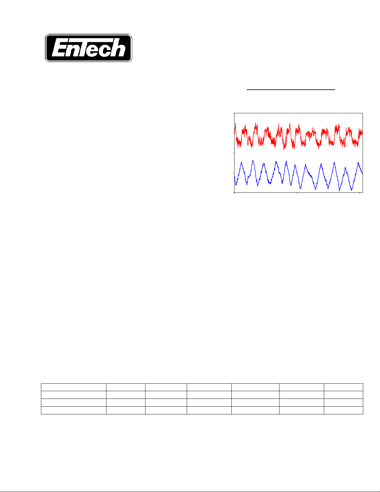
Controller Output % Flow %
Control Valve Dynamic Specification
(Summary - Version 3.0, 11/98)
Competitive Marketplace
The global market’s continuing demand for quality and uniformity in
manufactured products means there is even greater focus being given
to process control equipment and its performance. EnTech Control
Engineering Inc. has specialized in the optimization of process
performance, particularly in pulp and paper manufacturing where
product uniformity specifications are now approaching 1%. Plant
process variability audits frequently find that product variability is
increased by individual control loops that limit cycle because their
control valves are unable to track their controller output signals closely
enough (Figure 1). This undesirable behaviour of control valves is
the biggest single contributor to poor control loop performance
and the destabilization of process operation.
Purpose: to define the degree to which control valves can be
nonlinear and still allow acceptable process control performance.
About Version 3.0: The original EnTech Control Valve Dynamic Specification was issued in 1992. Version 3.0 replaces all
previous versions. It uses ISA terminology, considers end user needs, defines a valve step response performance index, and is
applicable to all process industries. All words in italics are defined in the definitions section: see full text of the specification.
55
53
51
49
47
0 500 1000
Time seconds
Figure 1 – Typical Control Valve Induced Limit Cycle
Control Valve System: The Specification considers the control valve as a dynamic system, from input signal through to
the flow coefficient that determines the fluid flow in the pipe. The key is that a measured change in a process variable is
expected in response to small input step-changes (1% and less). Valve stem movement is not an adequate indication, but is
considered to be a good measure of the speed of response of the valve system.
SPECIFICATION
There are three sections: Nonlinear, Dynamic Step Response and Valve Sizing. Each has a number of recommendations, a
default value, and an extra space for a user-specified selection. If no control loop application knowledge is available, the
default values should be used. The performance of a control valve system shipped as a package should be
documented in a specification sheet, including the parameters called out in this specification.
1. NONLINEAR SPECIFICATION
The nonlinear specification sets the maximum allowed dead band, step resolution and total hysteresis. The total hysteresis
influences the potential minimum step size, which in turn determines the amplitude of the potential controller output limit cycle.
The minimum step size together with the flow gain determines the amplitude of the potential PV limit cycle. Three classes are
given: nominal, fine and very fine. Default values are provided for both rotary valves and sliding stem valves.
Valve Tracking Nonlinearities (% input signal) DEFAULT DEFAULT
Class Nominal - 1% Fine - 0.5% V Fine – 0.1% Rotary Valves Sliding Stem User
Dead Band (%)
Step Resolution (%)
Total Hysteresis (%)
0.6 0.3 0.06
0.4 0.2 0.04
1.0 0.5 0.1
2. DYNAMIC STEP RESPONSE SPECIFICATION - STEP SIZE RANGE – REGION C
The dynamic response specification sets the ranges over which consistent dynamics are to be achieved (Region C). The step
size range is set from minimum to maximum. Minimum step size depends on the total hysteresis, as well as the magnitude of
Region B. It is valve design dependent and is likely to be about double the total hysteresis. Values are given for nominal, fine,
and very fine. The finer, the more capable the valve design. Default values are given for rotary and sliding stem valves.
0.6 0.3
0.4 0.2
1.0 0.5
Copyright EnTech 1998 – All Rights Reserved
Page 2

Minimum Step Size (%) DEFAULT DEFAULT
Nominal Fine Very Fine Rotary Valves Sliding Stem User
2.0 1.0 0.2
2.0 1.0
The Maximum step size determines the upper range over which the valve is nearly linear and depends on the size of Region D.
Values are given for nominal, wide and very wide. The wider, the more capable the valve design.
Maximum Step Size (%)
Nominal Wide Very Wide DEFAULT User
10 50 100
10
STEP RESPONSE - REGION C – Consistent Dynamics
The step response specification sets T86, % Overshoot, Travel Gain, Tss. Each class is based on the fastest control loop
speed of response (λ) available, given the valve T86 and Tss as specified. The four classes include: Very Fast (1 second),
Fast (5 seconds), Nominal (10 seconds), Slow (1 minute). The default is set for 5 sec.
T86 Step Response Time (seconds) by Fastest Loop Speed of Response Class (Function of Td / T86 Ratio)
Class 1 second 5 seconds 10 seconds 1 minute DEFAULT User
Td / T86 < 0.5
Td / T86 > 0.5
0.4 2 4 24
0.25 1.25 2.5 15
2
1.25
Tss Steady State Time (seconds) by Fastest Loop Speed of Response Class (Function of Td / T86 Ratio)
Class 1 second 5 seconds 10 seconds 1 minute DEFAULT User
Td / T86 < 0.5
Td / T86 > 0.5
1 5 10 60
0.63 3.1 6.3 38
5
3.2
Travel gain %Overshoot (% of step change)
Nominal DEFAULT User Nominal DEFAULT User
0.8 to 1.2
0.8 to 1.2
20
20
Valve Performance Index W - Weighting Factor - (Based on Equations 1 and 2) 0=perfect, 100=poor
W(T86) Equation 1 = W(Lambda) Equation 2 =
3. VALVE SIZING SPECIFICATION
Flow Characteristic Nonlinearities:
This section of the specification is intended as a guideline for control valve sizing calculations. The flow limit cycle amplitude
can be predicted as one half of the minimum step size times the flow gain. It can best be expressed as potential process
variability on a percentage basis, by calculating the limit cycle amplitude as a percentage of the nominal flow. The flow gain %
is the flow gain in flow units / valve travel %, divided by the flow at the operating point and expressed as a percent. The
designer should consider the worst case in the process design (highest or lowest flow).
Maximum Allowed Flow Limit Cycle Amplitude (% of Nominal Flow) DEFAULT DEFAULT
Nominal Fine Very Fine Rotary Valves Sliding Stem User
Minimum Step Size (%)
Flow Gain %
Flow Limit Cycle (%)
2.0 1 0.2
1.0 1.0 1.0
1.0 0. 5 0.1
2.0 1
1.0 1.0
1.0 0. 5
The control loop process gain is a function of the flow gain, the relationship of the flow in the pipe to the measured process
variable, and the span of the transmitter used to make the process measurement. Ideally, the process gain should be
approximately equal to unity (% PV / % valve travel) for good design. The amount by which the process gain varies over the
operating range of the process, determines the degree to which the control loop will be difficult to tune. Poor tuning leads to
control loop cycling and higher process variability. Ideally the process gain range should be limited to plus and minus a factor
of two.
Variation in Process Gain (Kp), DEFAULT DEFAULT
Nominal High Low High Low User
Nominal Kp (%/%)
1.0 2.0 0.5
2.0 0.5
A full copy of the specification is available via the EnTech home page at: http://www.entechcontrol.com/, or by calling EnTech.
2
Copyright EnTech 1998 – All Rights Reserved
Page 3

For more information:
For more information on Variability Management please visit our website
www.EmersonProcess.com/solutions/VariabilityManagement , or
Contact us at:
AAT@emersonprocess.com
email:
phone: +1 512-832-3575
Emerson Process Management
12301 Research Blvd.
Research Park Plaza, Building III
Austin, Texas 78759 USA
 Loading...